
Optimisation of Strength Properties of FDM Printed Parts—A Critical Review

 ,
,  , and
, and
Abstract
1. Introduction
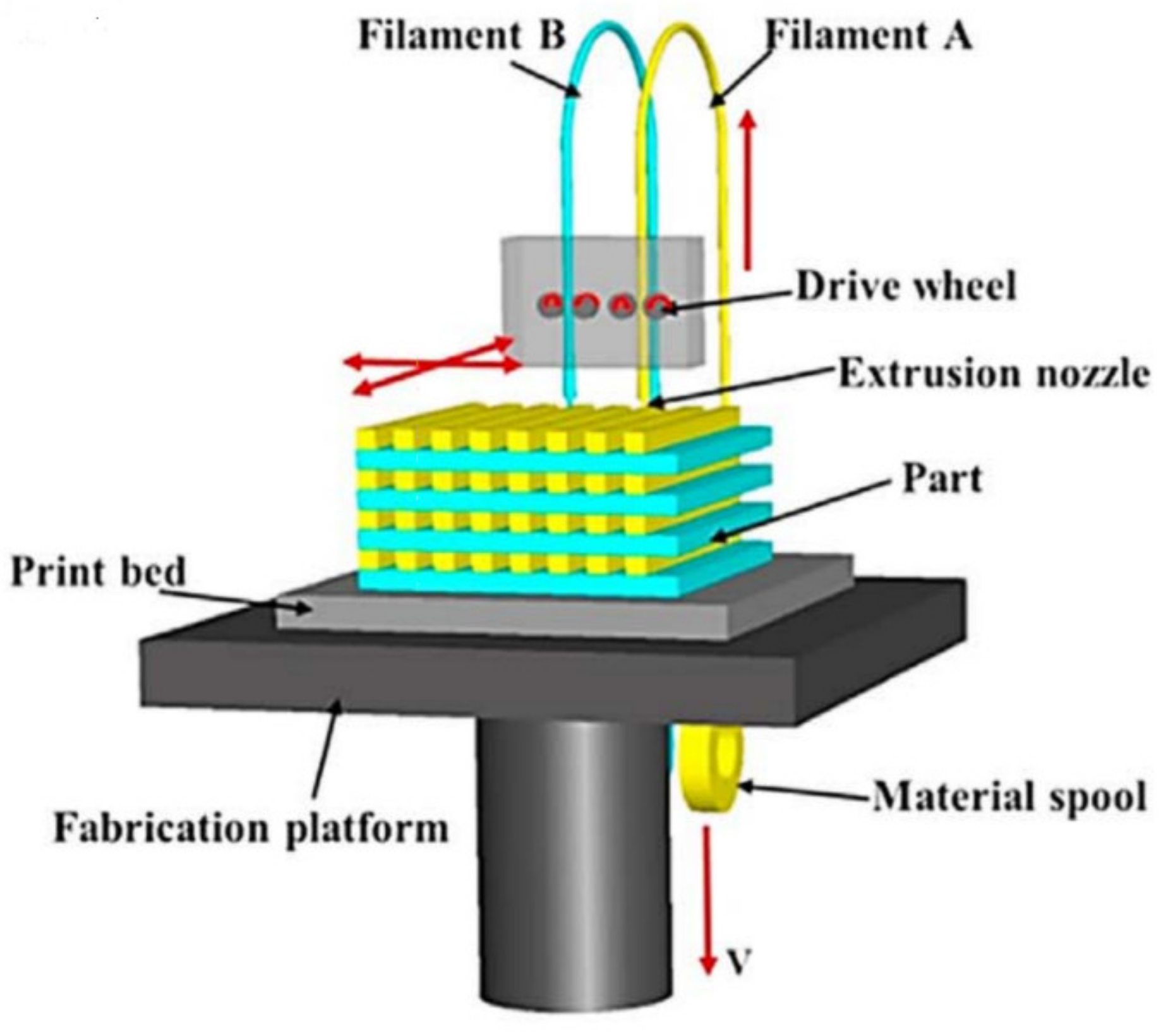
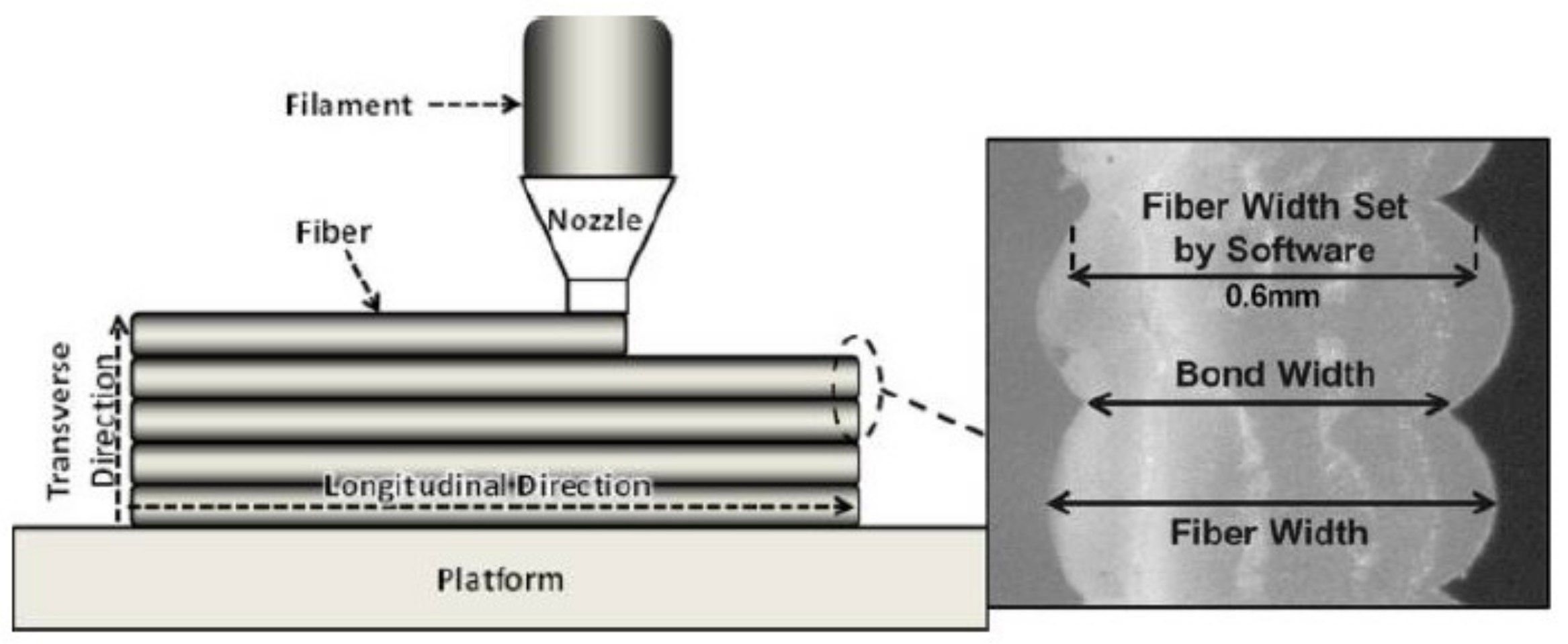
1.1. Overview of FDM Process
1.2. Bond Formation Mechanism
1.3. Application of FDM Products
2. Influence of Process Parameters on the Strength of FDM Parts
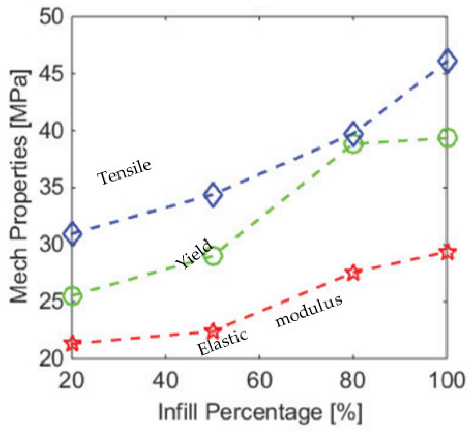
2.1. Effect of Infill Density
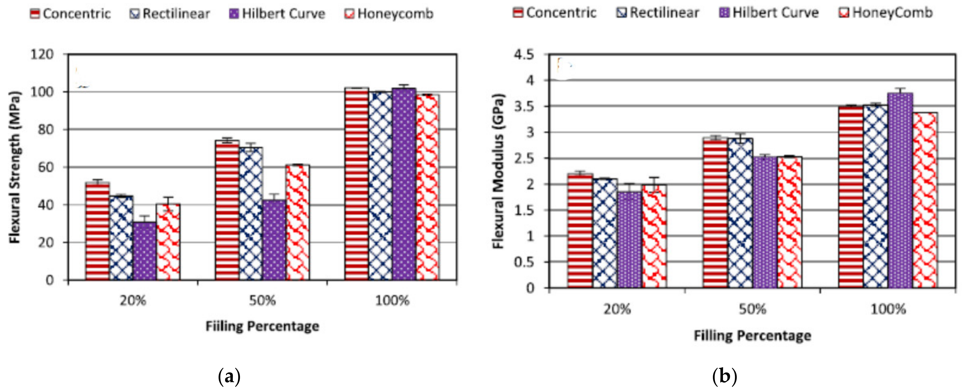
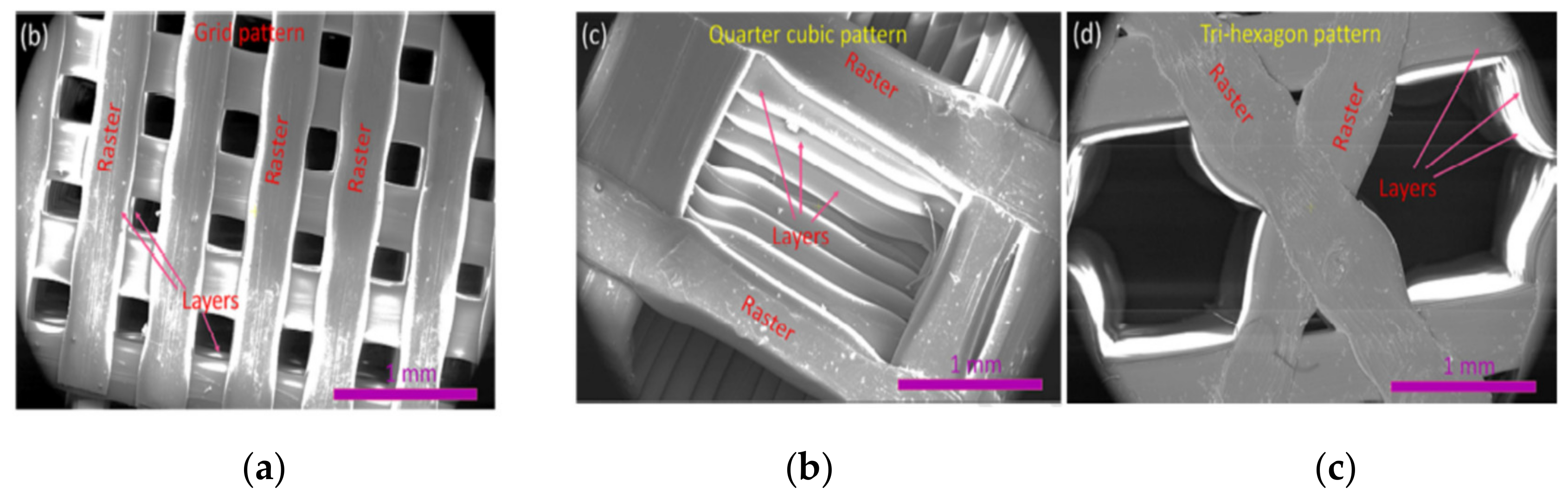
2.2. Effect of Infill Patterns
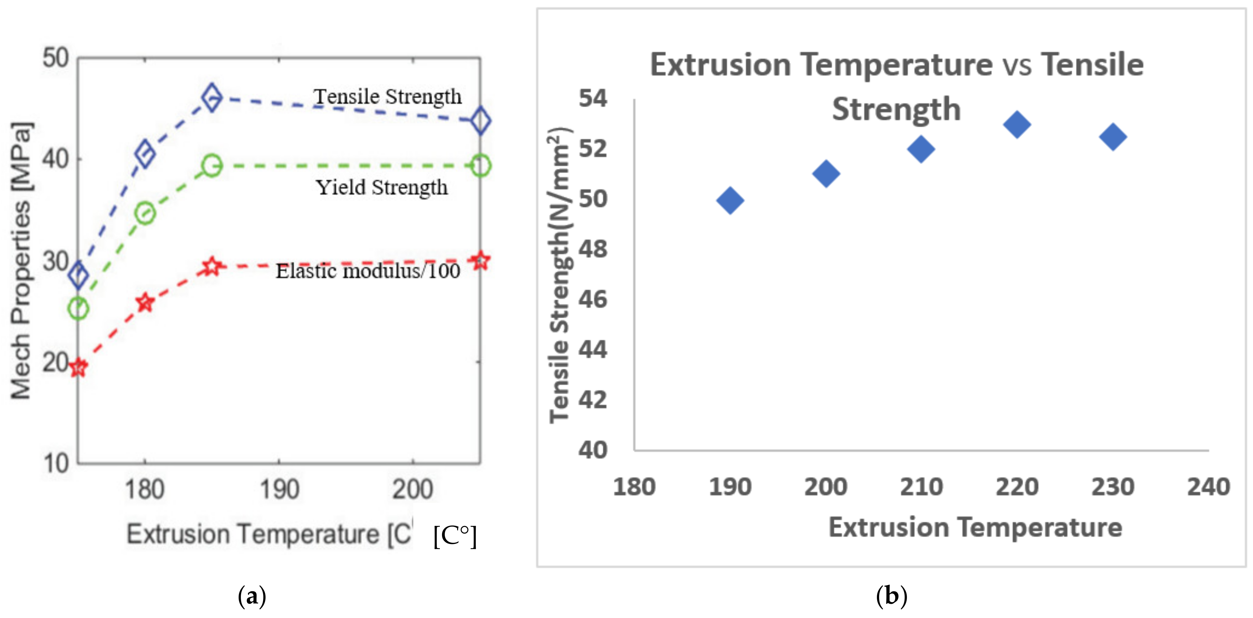
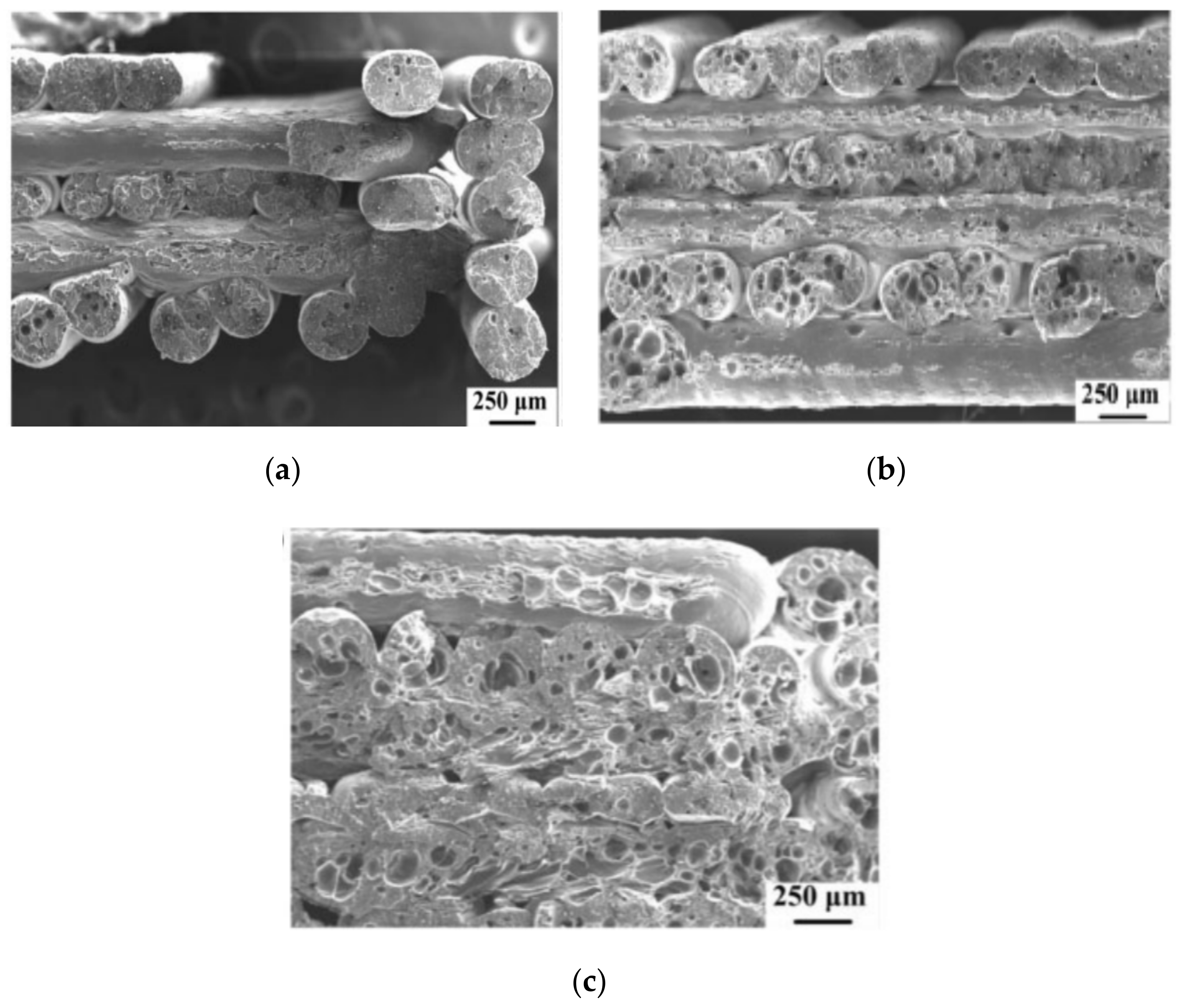
2.3. Effect of Extrusion Temperature
2.4. Effect of the Nozzle Diameter
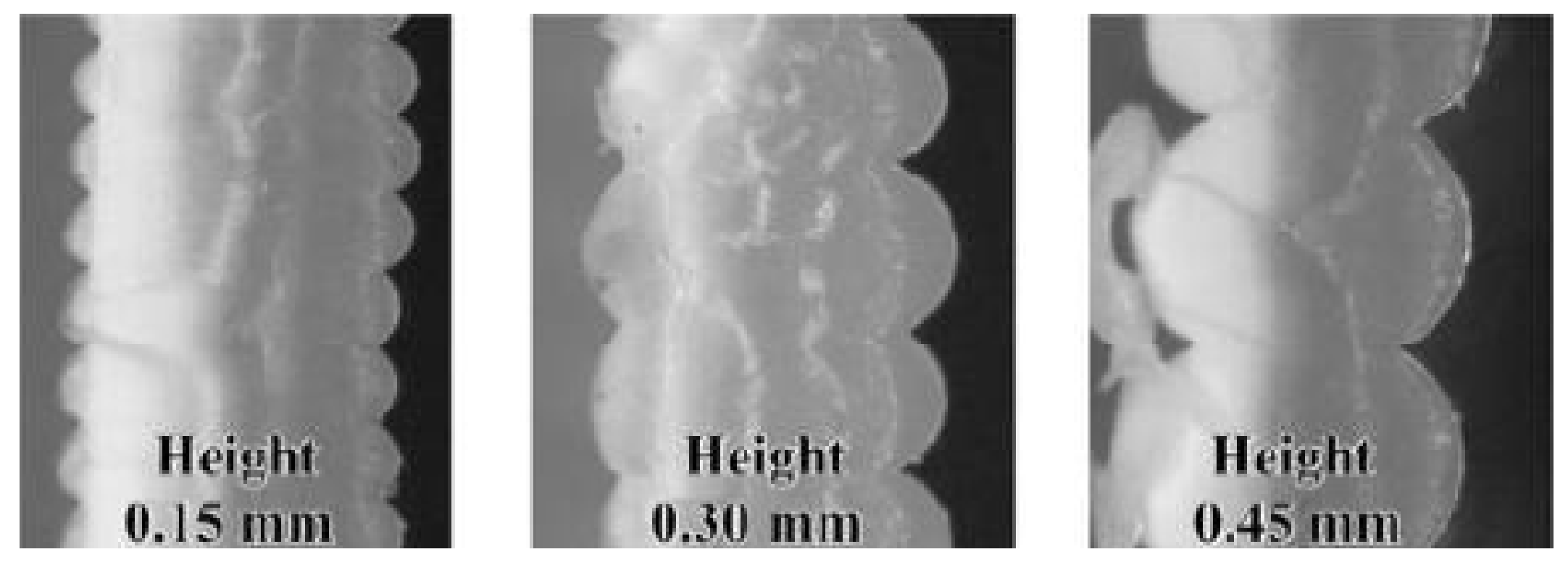
2.5. Effect of Layer Thickness
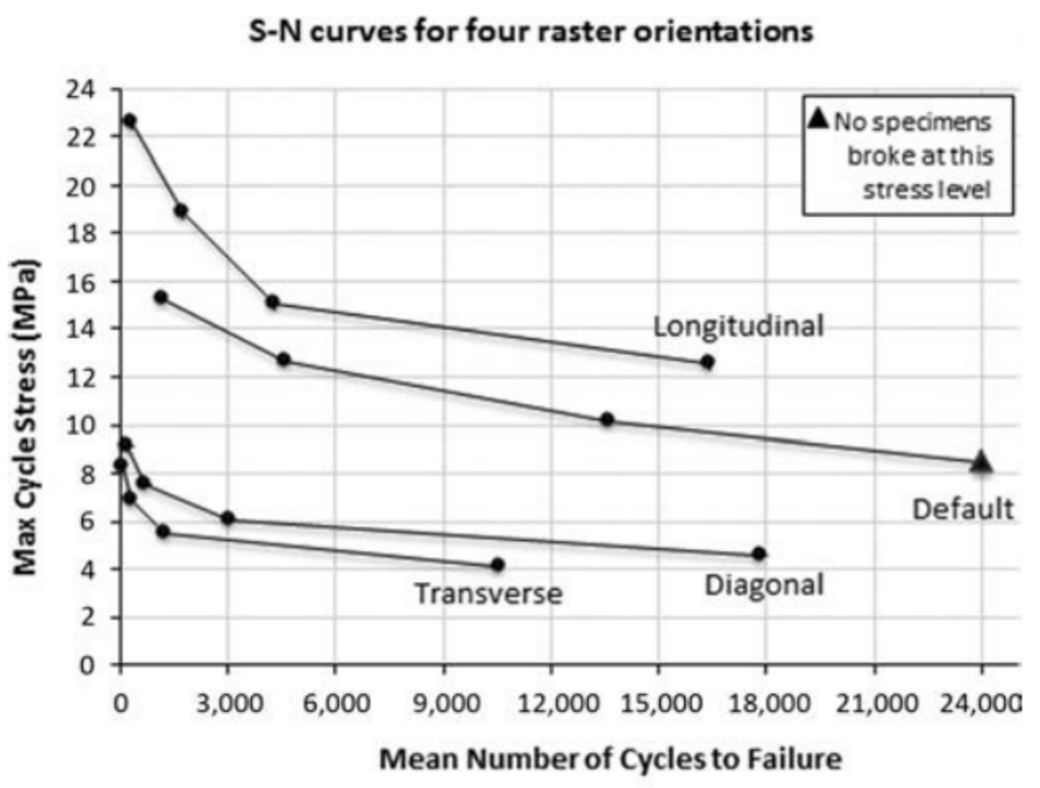
2.6. Effect of Raster Angle
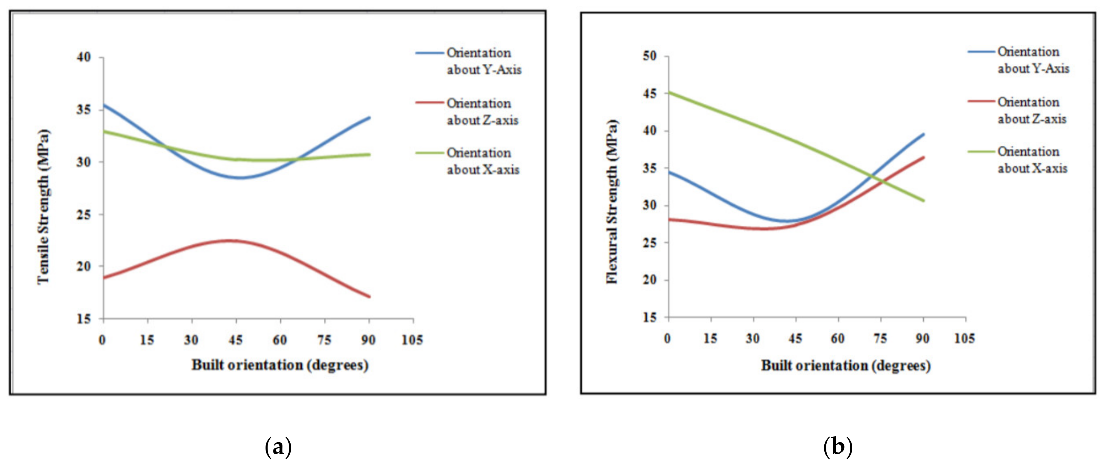
2.7. Effect of Build Orientation
3. Impact of Pre-Processing on the Strength of FDM

| Articles | Material | Printing Speed (cm/s) | Deposition Temperature | Light Source | Power of the Light Source | Preheating Temperature |
|---|---|---|---|---|---|---|
| (Kishore et al., 2017) [98] | Acrylonitrile butadiene styrene (ABS) reinforced with 20 wt.% short carbon fiber | 3.8, 5.1, 7.6 | 215 °C | Infrared lamp 500 W for case 1 and 2 1 kW for case 3 | 100% for case 1 and 2 80–90% for case 3 | N/A |
| (Kishore et al., 2019) [99] | Acrylonitrile butadiene styrene (ABS) reinforced with 20 wt.% short carbon fiber | 5.1 | 215 °C | Strip IR model number 5306B-02-1000-01-00 (the same lamp that was used for case 3 previously) | 80% | 150 °C |
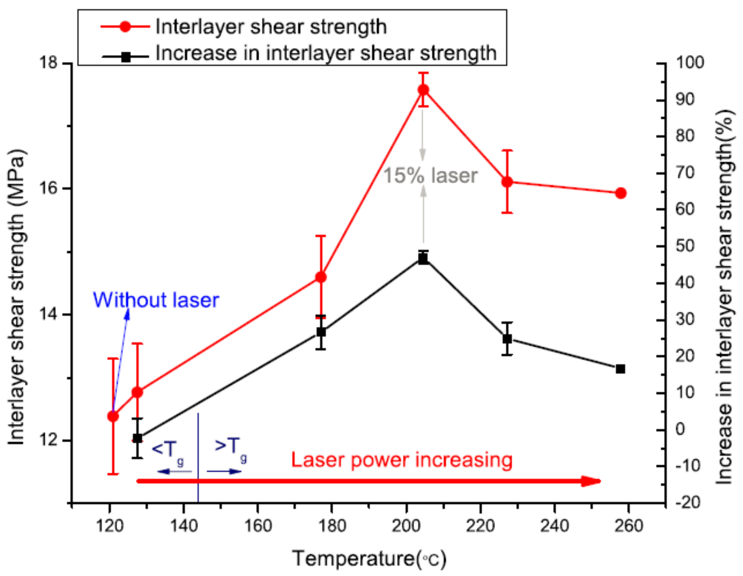
| (Luo et al., 2018) [101] | semicrystalline thermoplastic polymers | 0.6 | 410 °C | 40 W CO2 laser (10.6 μm wavelength) | 5, 10, 15, 20, 25% | Varied with the power of the light source |
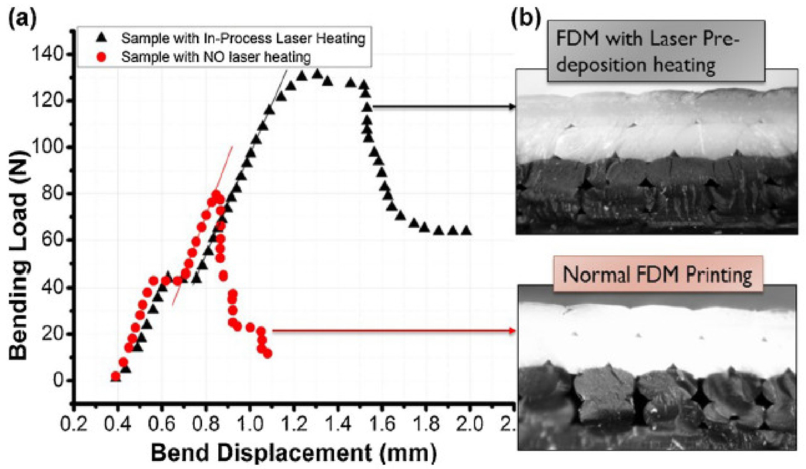
| (Ravi, 2016) [102] | black-color ABS filaments | 0.1–1 | 230 °C | 802 nm solid-state laser (2 W) | 0.75 W | Varied with the power of the light source |
| (Du, 2016) [103] | ABS polymers | 1–2 | Not specified | Laser (2 W) | 0–2 W | By 20–30 °C |
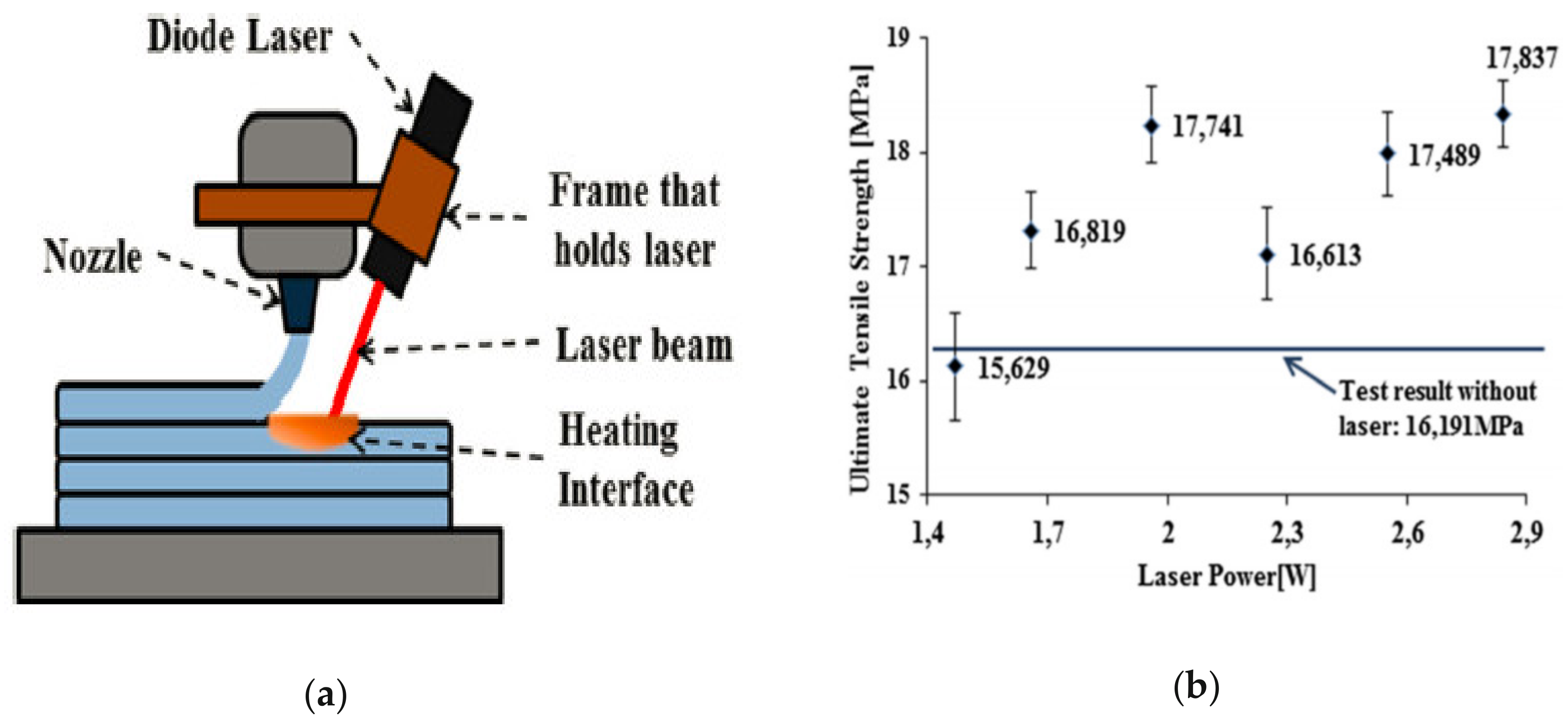
| (Sabyrov, 2020) [104] | PLA plastic | 3.5 | 210 °C | Diode laser (5 W) | 1.47, 1.66, 1.96, 2.25, 2.55, 2.84 W | Varied with the power of the light source |
4. Research Trends
4.1. Vacuum-Assisted FDM
4.2. Advances in Materials
| Material | Authors | Percentage Added and Description of the Additives | Notes (The Increase/Decrease of the Mechanical Properties are Considered Relative to Pure ABS) |
|---|---|---|---|
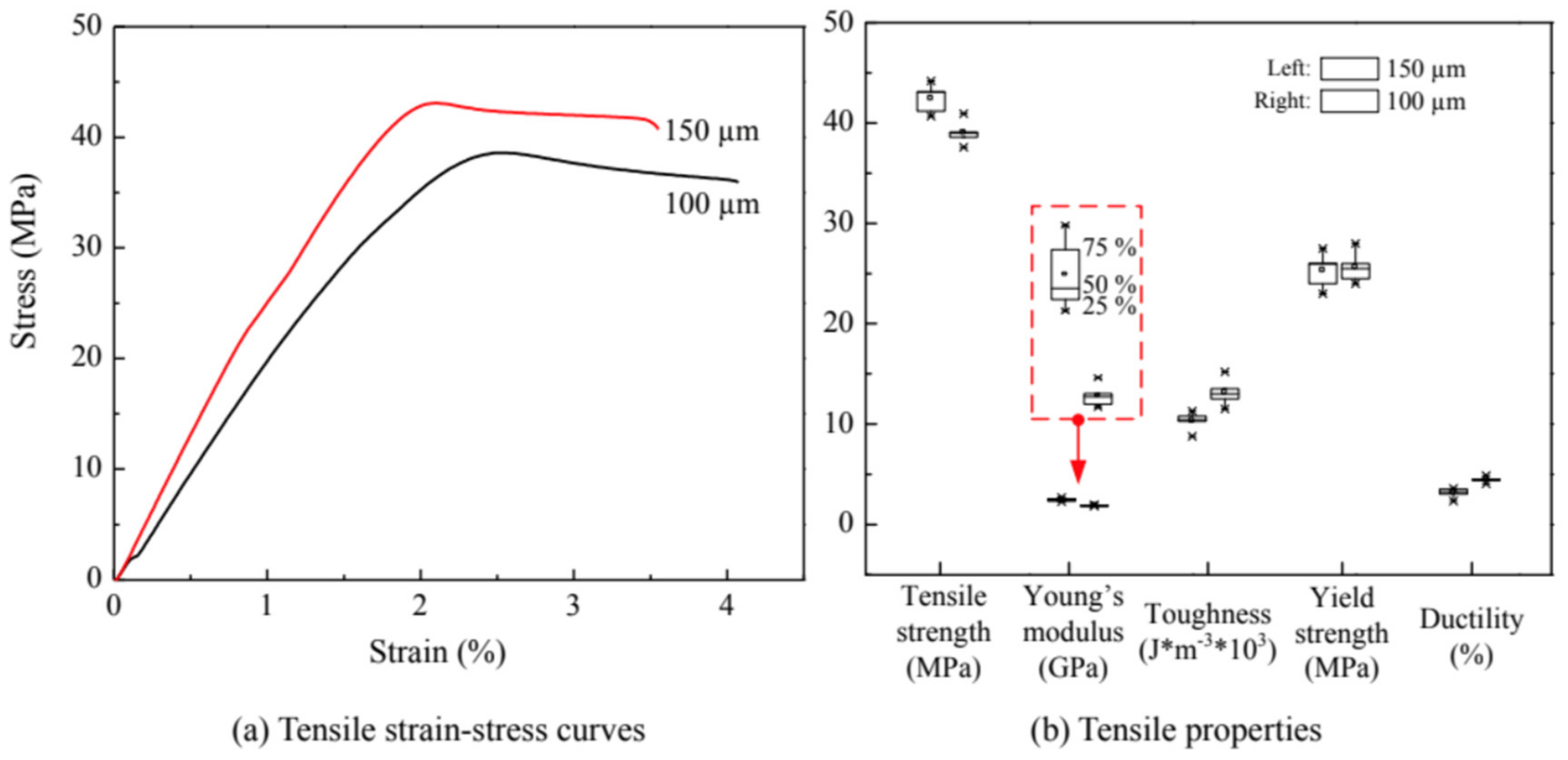
| ABS + carbon fibers | Ning et al. (2015) [119] | 3, 5, 7.5, 10, 15 wt.%; 150 μm and 100 μm in length with a common diameter of 7.2 μm |
|
| Tekinalp et al. (2014) [118] | 10, 20, 30, 40 wt.%; the fibers’ length—200–400 μm. |
| |
| Shofner et al. (2003) [117] | 10 wt.% only; the average diameter—100 nm, length—100 μm |
| |
| ABS + carbon nanotubes (CNT) | Sezer, H.K., and Eren, O. (2019) [121] | 1, 3, 5, 7, 10 wt.%; average diameter—9.5 nm; average length—1.5 μm; surface area—250–300 m2/g |
|
| Dul et al. (2018) [120] | 1, 2, 4, 6, 8 wt %; average diameter—9.5 nm; average length—1.5 μm; surface area—250–300 m2/g |
| |
| ABS + ZnO | Aw et al. (2017) [122] | 8, 11, 14 wt.%; Particle’s size < 100 μm |
|
| Torrado et al. (2015) [123] | 2 wt.% only; ZnO nanorods were used (no information about the size) |
| |
| DulABS + graphene | Dul et al. (2016) [128] | 2, 4, 8 wt.%; average lateral dimension –5 μm, thickness—6–8 nm, the surface area—120–150 m2/g. |
|
| PC + ABS + graphene | Tambrallimath et al. (2019) [116] | 0.2, 0.4, 0.6, 0.8 wt.%; PC:ABS = 70:30; No dimensions of graphene platelets were provided |
|
| ABS + OMMT | Weng et al. (2016) [133] | 1, 3, 5 wt.%; No dimensions of OMMT nanoparticles were given |
|
| ABS + BAK + Al2O3 + SiC | Singh et al. (2019a) [125] | BAK: fixed value of 10 wt.%; Al2O3: 0, 5, 10 wt.%; SiC: 0, 5, 10 wt.%; No dimensions were given |
|
| Singh et al. (2019b) [126] |
|
4.3. Advances in Technology
| Type | Authors, Number of Patent | Bullet Points |
|---|---|---|
| Filament storage and printer heads | Mark et al. (2017) US9815268 [140] |
|
| Mark and Gozdz (2015) US9126367 [139] |
| |
| Pax and Schmehl (2014) US20140044823 [137] |
| |
| Swanson et al. (2013) US8465111 [138] |
| |
| Taatjes et al. (2012) US8157202 [135] |
| |
| Comb et al. (2012) US8153182 [136] |
| |
| Support materials | Hopkins et al. (2012) US8246888 [142] |
|
| Tafoya (2013) US8505560 [143] |
| |
| Novel technique | Lewis et al. (2016) US20160346997 [141] |
|
| Auxiliary measures | Paul and Batchelder (2012) US8222908 [144] |
|
| Biotechnology | Boehm et al. (2013) US20130326878 [145] |
|
5. Summary
- From the previous discussion, it can be seen that process parameters play a significant role in the determination of the mechanical properties of the part made by FDM. The literature review shows that layer thickness is the most important factor among the studied ones and the information about its effect is contradictory and mainly depends on the type of load applied as well as the raw filament material. Some findings are summarized in Table 1. It can be seen that the data on the effect of the layer thickness are divergent and more work is needed to relate the following parameters and mechanical properties.
- Considering the effect of the infill percentage, all works agree that the increase of infill density increases the strength at break. On the other hand, the same works express the stress at the break as the ratio of load and cross-sectional area without taking into account unfilled space. This is why proper metrics should be developed to account for this issue either by reporting strength per mass (as in the case of Akhoundi, et al. (2019)) or multiplying the stressed area by the infill ratio.
- It also appears that the ratio of the nozzle diameter to the layer thickness may be a major factor affecting the UTS and flexural strength of the FDM printed parts. However, there are currently limited data available on the effect of the nozzle diameter or nozzle diameter/layer thinness ratio, on the impact and compressive strength. Therefore, there is room for further investigation in this direction.
- Extrusion temperature is also able to increase the stress as the bonding between layers and neighbor filaments is facilitated. On the other hand, there is a limit up until which the extrusion temperature can be increased without worsening mechanical properties (Ning, et al. (2016), Guessasma, et al. (2019)).
- Most research indicates lower levels (0° or 15°) of build orientation to be optimal in terms of the tensile strength of FDM parts, whereas the flexural and impact strength properties show different optimal orientations in different studies.
- It was reported that the minimum level (0°) of raster angle improves the tensile strength of FDM parts, while the impact strength can be improved using a 45°/−45° (staggered raster) raster angle.
- The FDM enhancement technique was analyzed based on several existing experiments. The pre-deposition heating method of the extruded layer surface showed a positive impact on the mechanical properties of the printed design. It was also found that the anisotropy effect was reduced after preheating.
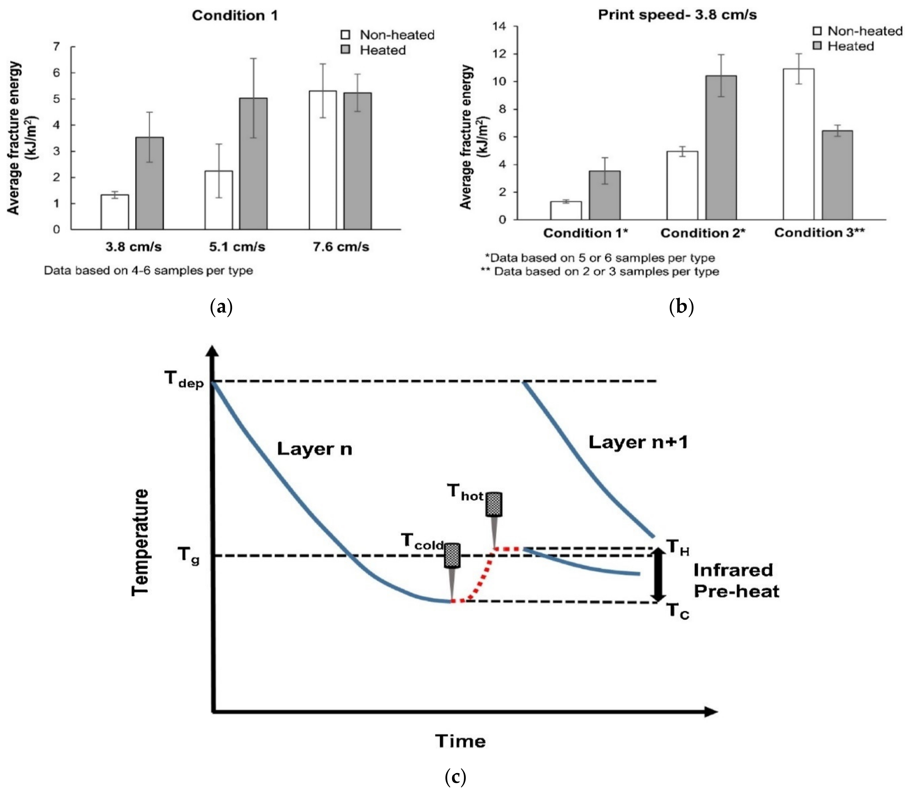
- In order to enhance the interlayer bonding temperature and interlaminar strength, the IR lamp heating method was reported to be successful. The printing speed of 3.8 and 5.1 cm/s with two IR lamps of 500 W placed over 8 cm above the deposited layer offers double the fracture energy compared to the nonheated part. A printing speed of 3.8 cm/s and with two IR lamps of 500 W placed over 2.5 cm above the deposited layer also demonstrates a similar result, however, a 1 KW IR lamp placed 1 t 1 cm away from the printed surface results in poor fracture energy due to high intensity of IR that results in degradation of the materials. The idea of IR preheating was to raise the substrate temperature moderately above the glass transition temperature just before the next layer deposition. Lamp configuration and active controlling of substrate temperature need to be investigated further for more insight.
- Incorporation of vacuum in the printing chamber has shown to improve the quality of the printing due to the decrease in heat transfer from the nozzle, hence providing a smooth and slow decrease of the temperature of the polymer that helps to improve the bonding between the layers. Therefore, the tensile strength was found to be increased by 12.83% (from 12.85 MPa to 14.50 MPa) compared to the normal printing conditions.
- One of the current trends in Additive Manufacturing (AM) is to include reinforcement to the polymers in order to enhance the mechanical properties of the printed workpieces such as tensile strength and Young’s modulus. The geometry (such as length) of the reinforcement, their orientation in the matrix and the printing conditions are also significant factors in deciding the strength properties of the FDM parts. According to the literature, the fact that most of the fibers tend to orient along the direction of the extrusion means this inherent preferential orientation resulted in an increased property since this direction of extrusion coincided with the load-bearing direction of the specimens.
- As per the literature, most of the studies reported on the tensile properties of the fabricated part, and few studies also reported on flexural strength of the part. In-depth research on flexural strength properties is required to be investigated further in terms of layer thickness, printing speed, extrusion temperature and number of contours. Other than tensile and flexural properties, other properties such as shear stress, impact test to measure the service life of parts also need to be investigated.
- Additionally, research related to linear as well as the circular feature is mostly undertaken, therefore, more complicated shapes with overhangs, gradients and curvature that replicate more real-time problems need to be investigated for strength properties.
- Strength property investigation for dissimilar materials such as plastic and metal are also needed to be done. Due to the different melting points of dissimilar materials, their bonding mechanism also needs to be investigated especially. Additionally, the effect of cavity generated in FDM parts on strength properties needs to be investigated.
- Although infill pattern and infill density have been investigated in the literature, infill pattern with low infill percentage needs to be investigated. In addition, along with other important factors, cooling rate and environmental conditions need to be considered as well.
- Currently, pre-enhancement techniques such as laser heating are mostly in use as per the literature. Other pre-enhancement techniques and post enhancement techniques such as coating also need special attention.
- The FDM part used for medical purposes undergoes a sterilization process, and therefore, the effect of the sterilization technique on the strength properties also needs to be investigated.
Author Contributions
Funding
Institutional Review Board Statement
Informed Consent Statement
Data Availability Statement
Conflicts of Interest
References
- Gibson, I.; Rosen, D.; Stucker, B. Direct digital manufacturing. In Additive Manufacturing Technologies; Springer: New York, NY, USA, 2015; pp. 375–397. [Google Scholar]
- Mueller, B. Additive manufacturing technologies–Rapid prototyping to direct digital manufacturing. Assem. Autom. 2012, 32. [Google Scholar] [CrossRef]
- Li, H.; Wang, T.; Sun, J.; Yu, Z. The effect of process parameters in fused deposition modelling on bonding degree and mechanical properties. Rapid Prototyp. J. 2018, 24, 80–92. [Google Scholar] [CrossRef]
- Kai, C.C. Three-dimensional rapid prototyping technologies and key development areas. Comput. Control Eng. J. 1994, 5, 200–206. [Google Scholar]
- Turner, B.N.; Strong, R.; Gold, S.A. A review of melt extrusion additive manufacturing processes: I. Process design and modeling. Rapid Prototyp. J. 2014, 20, 192–204. [Google Scholar] [CrossRef]
- Turner, B.N.; Gold, S.A. A review of melt extrusion additive manufacturing processes: II. Materials, dimensional accuracy, and surface roughness. Rapid Prototyp. J. 2015, 21, 250–261. [Google Scholar] [CrossRef]
- Popescu, D.; Zapciu, A.; Amza, C.; Baciu, F.; Marinescu, R. FDM process parameters influence over the mechanical properties of polymer specimens: A review. Polym. Test. 2018, 69, 157–166. [Google Scholar] [CrossRef]
- Vyavahare, S.; Teraiya, S.; Panghal, D.; Kumar, S. Fused deposition modelling: A review. Rapid Prototyp. J. 2020, 26, 176–201. [Google Scholar] [CrossRef]
- Cuan-Urquizo, E.; Barocio, E.; Tejada-Ortigoza, V.; Pipes, R.B.; Rodriguez, C.A.; Roman-Flores, A. Characterization of the mechanical properties of FFF structures and materials: A review on the experimental, computational and theoretical approaches. Materials 2019, 12, 895. [Google Scholar] [CrossRef]
- Coogan, T.J.; Kazmer, D.O. Healing simulation for bond strength prediction of FDM. Rapid Prototyp. J. 2017, 23, 551–561. [Google Scholar] [CrossRef]
- Mohamed, O.A.; Masood, S.H.; Bhowmik, J.L. Optimization of fused deposition modeling process parameters: A review of current research and future prospects. Adv. Manuf. 2015, 3, 42–53. [Google Scholar] [CrossRef]
- Chohan, J.S.; Singh, R.; Boparai, K.S.; Penna, R.; Fraternali, F. Dimensional accuracy analysis of coupled fused deposition modeling and vapour smoothing operations for biomedical applications. Compos. Part B Eng. 2017, 117, 138–149. [Google Scholar] [CrossRef]
- Sood, A.K.; Ohdar, R.K.; Mahapatra, S.S. Parametric appraisal of mechanical property of fused deposition modelling processed parts. Mater. Des. 2010, 31, 287–295. [Google Scholar] [CrossRef]
- Parandoush, P.; Lin, D. A review on additive manufacturing of polymer-fiber composites. Compos. Struct. 2017, 182, 36–53. [Google Scholar] [CrossRef]
- Wang, X.; Jiang, M.; Zhou, Z.; Gou, J.; Hui, D. 3D printing of polymer matrix composites: A review and prospective. Compos. Part B Eng. 2017, 110, 442–458. [Google Scholar] [CrossRef]
- Frenkel, J. Viscous flow of crystalline bodies under the action of surface tension. J. Phys. 1945, 9, 385. [Google Scholar]
- Bellehumeur, C.; Li, L.; Sun, Q.; Gu, P. Modeling of bond formation between polymer filaments in the fused deposition modeling process. J. Manuf. Process. 2004, 6, 170–178. [Google Scholar] [CrossRef]
- Sun, Q.; Rizvi, G.; Bellehumeur, C.; Gu, P. Effect of processing conditions on the bonding quality of FDM polymer filaments. Rapid Prototyp. J. 2008, 14, 72–80. [Google Scholar] [CrossRef]
- Rodríguez, J.F.; Thomas, J.P.; Renaud, J.E. Mechanical behavior of acrylonitrile butadiene styrene (ABS) fused deposition materials. Experimental investigation. Rapid Prototyp. J. 2001, 7, 148–158. [Google Scholar] [CrossRef]
- Bellini, A.; Güçeri, S. Mechanical characterization of parts fabricated using fused deposition modeling. Rapid Prototyp. J. 2003, 9, 252–264. [Google Scholar] [CrossRef]
- Gurrala, P.K.; Regalla, S.P. Part strength evolution with bonding between filaments in fused deposition modelling: This paper studies how coalescence of filaments contributes to the strength of final FDM part. Virtual Phys. Prototyp. 2014, 9, 141–149. [Google Scholar] [CrossRef]
- Pokluda, O.; Bellehumeur, C.T.; Vlachopoulos, J. Modification of Frenkel’s model for sintering. AICHE J. 1997, 43, 3253–3256. [Google Scholar] [CrossRef]
- Yin, J.; Lu, C.; Fu, J.; Huang, Y.; Zheng, Y. Interfacial bonding during multi-material fused deposition modeling (FDM) process due to inter-molecular diffusion. Mater. Des. 2018, 150, 104–112. [Google Scholar] [CrossRef]
- Campbell, I.; Diegel, O.; Kowen, J.; Wohlers, T. Wohlers Report 2018: 3D Printing and Additive Manufacturing State of the Industry: Annual Worldwide Progress Report; Wohlers Associates: Fort Collins, CO, USA, 2018. [Google Scholar]
- Najmon, J.C.; Raeisi, S.; Tovar, A. Review of additive manufacturing technologies and applications in the aerospace industry In Additive Manufacturing for the Aerospace Industry; Elsevier: Amsterdam, The Netherlands, 2019; pp. 7–31. [Google Scholar]
- Negis, E. A short history and applications of 3D printing technologies in Turkey. In Proceedings of the US-TURKEY Workshop on Rapid Technologies, Istanbul, Turkey, 24–25 September 2009. [Google Scholar]
- Bayar, M.S.; Aziz, Z. Rapid prototyping and its role in supporting architectural design process. J. Archit. Eng. 2018, 24, 05018003. [Google Scholar] [CrossRef]
- Klippstein, H.; Diaz De Cerio Sanchez, A.; Hassanin, H.; Zweiri, Y.; Seneviratne, L. Fused deposition modeling for unmanned aerial vehicles (UAVs): A review. Adv. Eng. Mater. 2018, 20, 1700552. [Google Scholar] [CrossRef]
- Hiemenz, J. Additive Manufacturing Trends in Aerospace; White Paper Stratasys: Eden Prairie, MN, USA, 2014; pp. 1–11. [Google Scholar]
- Bourell, D.; Stucker, B.; Ilardo, R.; Williams, C.B. Design and manufacture of a Formula SAE intake system using fused deposition modeling and fiber-reinforced composite materials. Rapid Prototyp. J. 2010, 16, 174–179. [Google Scholar]
- Okwuosa, T.C.; Stefaniak, D.; Arafat, B.; Isreb, A.; Wan, K.-W.; Alhnan, M.A. A lower temperature FDM 3D printing for the manufacture of patient-specific immediate release tablets. Pharm. Res. 2016, 33, 2704–2712. [Google Scholar] [CrossRef] [PubMed]
- Melgoza, E.L.; Vallicrosa, G.; Serenó, L.; Ciurana, J.; Rodríguez, C.A. Rapid tooling using 3D printing system for manufacturing of customized tracheal stent. Rapid Prototyp. J. 2014, 20, 2–12. [Google Scholar] [CrossRef]
- Domanski, J.; Skalski, K.; Grygoruk, R.; Mróz, A. Rapid prototyping in the intervertebral implant design process. Rapid Prototyp. J. 2015, 21, 735–746. [Google Scholar] [CrossRef]
- Yeong, W.-Y.; Chua, C.-K.; Leong, K.-F.; Chandrasekaran, M. Rapid prototyping in tissue engineering: Challenges and potential. Trends Biotechnol. 2004, 22, 643–652. [Google Scholar] [CrossRef]
- Peltola, S.M.; Melchels, F.P.; Grijpma, D.W.; Kellomäki, M. A review of rapid prototyping techniques for tissue engineering purposes. Ann. Med. 2008, 40, 268–280. [Google Scholar] [CrossRef]
- Kim, B.-S.; Mooney, D.J. Development of biocompatible synthetic extracellular matrices for tissue engineering. Trends Biotechnol. 1998, 16, 224–230. [Google Scholar] [CrossRef]
- Hutmacher, D.W.; Sittinger, M.; Risbud, M.V. Scaffold-based tissue engineering: Rationale for computer-aided design and solid free-form fabrication systems. Trends Biotechnol. 2004, 22, 354–362. [Google Scholar] [CrossRef]
- Korpela, J.; Kokkari, A.; Korhonen, H.; Malin, M.; Närhi, T.; Seppälä, J. Biodegradable and bioactive porous scaffold structures prepared using fused deposition modeling. J. Biomed. Mater. Res. Part B Appl. Biomater. 2013, 101, 610–619. [Google Scholar] [CrossRef]
- Lam, C.X.F.; Mo, X.; Teoh, S.-H.; Hutmacher, D. Scaffold development using 3D printing with a starch-based polymer. Mater. Sci. Eng. C 2002, 20, 49–56. [Google Scholar] [CrossRef]
- Lee, C.; Chua, C.; Cheah, C.; Tan, L.; Feng, C. Rapid investment casting: Direct and indirect approaches via fused deposition modelling. Int. J. Adv. Manuf. Technol. 2004, 23, 93–101. [Google Scholar]
- Petropolis, C.; Kozan, D.; Sigurdson, L. Accuracy of medical models made by consumer-grade fused deposition modelling printers. Plast. Surg. 2015, 23, 91–94. [Google Scholar] [CrossRef]
- Bourell, D.; Stucker, B.; Espalin, D.; Arcaute, K.; Rodriguez, D.; Medina, F.; Posner, M.; Wicker, R. Fused deposition modeling of patient-specific polymethylmethacrylate implants. Rapid Prototyp. J. 2010, 16, 164–173. [Google Scholar]
- Van Noort, R. The future of dental devices is digital. Dent. Mater. 2012, 28, 3–12. [Google Scholar] [CrossRef]
- Xu, N.; Ye, X.; Wei, D.; Zhong, J.; Chen, Y.; Xu, G.; He, D. 3D artificial bones for bone repair prepared by computed tomography-guided fused deposition modeling for bone repair. ACS Appl. Mater. Interfaces 2014, 6, 14952–14963. [Google Scholar] [CrossRef]
- Šljivić, M.; Stanojević, M.; Đurđević, D.; Grujović, N.; Pavlović, A. Implementation of FEM and rapid prototyping in maxillofacial surgery. FME Trans. 2016, 44, 422–429. [Google Scholar] [CrossRef]
- Melocchi, A.; Parietti, F.; Maroni, A.; Foppoli, A.; Gazzaniga, A.; Zema, L. Hot-melt extruded filaments based on pharmaceutical grade polymers for 3D printing by fused deposition modeling. Int. J. Pharm. 2016, 509, 255–263. [Google Scholar] [CrossRef]
- Zhang, B.; Seong, B.; Nguyen, V.; Byun, D. 3D printing of high-resolution PLA-based structures by hybrid electrohydrodynamic and fused deposition modeling techniques. J. Micromech. Microeng. 2016, 26, 025015. [Google Scholar] [CrossRef]
- Soriano-Heras, E.; Blaya-Haro, F.; Molino, C.; de Agustín del Burgo, J.M. Rapid prototyping prosthetic hand acting by a low-cost shape-memory-alloy actuator. J. Artif. Organs 2018, 21, 238–246. [Google Scholar] [CrossRef]
- Juneja, M.; Thakur, N.; Kumar, D.; Gupta, A.; Bajwa, B.; Jindal, P. Accuracy in dental surgical guide fabrication using different 3-D printing techniques. Addit. Manuf. 2018, 22, 243–255. [Google Scholar] [CrossRef]
- Chougule, V.N.; Mulay, A.V.; Ahuja, B.B. Methodologies for development of patient specific bone models from human body CT scans. J. Inst. Eng. Ser. C 2018, 99, 413–418. [Google Scholar] [CrossRef]
- Colpani, A.; Fiorentino, A.; Ceretti, E. In 3D printing for health & wealth: Fabrication of custom-made medical devices through additive manufacturing. In AIP Conference Proceedings; AIP Publishing LLC: Melville, NY, USA, 2018. [Google Scholar]
- Corcione, C.E.; Palumbo, E.; Masciullo, A.; Montagna, F.; Torricelli, M.C. Fused Deposition Modeling (FDM): An innovative technique aimed at reusing Lecce stone waste for industrial design and building applications. Constr. Build. Mater. 2018, 158, 276–284. [Google Scholar] [CrossRef]
- García-García, R.; González-Palacios, M.A. Method for the geometric modeling and rapid prototyping of involute bevel gears. Int. J. Adv. Manuf. Technol. 2018, 98, 645–656. [Google Scholar] [CrossRef]
- Pei, E.; Shen, J.; Watling, J. Direct 3D printing of polymers onto textiles: Experimental studies and applications. Rapid Prototyp. J. 2015, 21, 556–571. [Google Scholar] [CrossRef]
- Durgun, I.; Ertan, R. Experimental investigation of FDM process for improvement of mechanical properties and production cost. Rapid Prototyp. J. 2014, 20, 228–235. [Google Scholar] [CrossRef]
- Brooks, H.; Lupeanu, M.; Abram, T. Production of personalized lithophane lighting products using AM. In DAAAM International Scientific Book; DAAAM International: Vienna, Austria, 2012; Volume 11. [Google Scholar]
- Monzon, M.D.; Diaz, N.; Benitez, A.; Marrero, M.; Hernandez, P. Advantages of fused deposition modeling for making electrically conductive plastic patterns. In Proceedings of the 2010 International Conference on Manufacturing Automation, Hong Kong, China, 13–15 December 2010; IEEE: Piscataway, NJ, USA, 2010. [Google Scholar]
- Diegel, O.; Singamneni, S.; Huang, B.; Gibson, I. Curved layer fused deposition modeling in conductive polymer additive manufacturing. In Advanced Materials Research; Trans Tech Publications: Zurich, Switzerland, 2011. [Google Scholar]
- Diegel, O.; Singamneni, S.; Huang, B.; Gibson, I. Getting rid of the wires: Curved layer fused deposition modeling in conductive polymer additive manufacturing. In Key Engineering Materials; Trans Tech Publications: Zurich, Switzerland, 2011; pp. 662–667. [Google Scholar]
- Jatti, V.S.; Jatti, S.V.; Patel, A.P.; Jatti, V.S. A Study On Effect Of Fused Deposition Modeling Process Parameters On Mechanical Properties. Int. J. Sci. Technol. Res. 2019, 8, 689–693. [Google Scholar]
- Rodríguez-Panes, A.; Claver, J.; Camacho, A.M. The influence of manufacturing parameters on the mechanical behaviour of PLA and ABS pieces manufactured by FDM: A comparative analysis. Materials 2018, 11, 1333. [Google Scholar] [CrossRef]
- Ramkumar, P. Investigation on the effect of process. Parameters on impact strength of fused deposition modelling specimens. In IOP Conference Series: Materials Science and Engineering; IOP Publishing: Bristol, UK, 2019. [Google Scholar]
- Radhwan, H.; Shayfull, Z.; Abdellah, A.E.-H.; Irfan, A.; Kamarudin, K. Optimization parameter effects on the strength of 3D-printing process using Taguchi method. In AIP Conference Proceedings; AIP Publishing LLC: Melville, NY, USA, 2019; p. 020154. [Google Scholar]
- Vicente, C.M.; Martins, T.S.; Leite, M.; Ribeiro, A.; Reis, L. Influence of fused deposition modeling parameters on the mechanical properties of ABS parts. Polym. Adv. Technol. 2020, 31, 501–507. [Google Scholar] [CrossRef]
- Pei, E.; Melenka, G.W.; Schofield, J.S.; Dawson, M.R.; Carey, J.P. Evaluation of dimensional accuracy and material properties of the MakerBot 3D desktop printer. Rapid Prototyp. J. 2015, 21, 618–627. [Google Scholar]
- Qattawi, A.; Alrawi, B.; Guzman, A. Experimental optimization of fused deposition modelling processing parameters: A design-for-manufacturing approach. Procedia Manuf. 2017, 10, 791–803. [Google Scholar]
- Akhoundi, B.; Behravesh, A. Effect of filling pattern on the tensile and flexural mechanical properties of FDM 3D printed products. Exp. Mech. 2019, 59, 883–897. [Google Scholar] [CrossRef]
- Aloyaydi, B.; Sivasankaran, S.; Mustafa, A. Investigation of infill-patterns on mechanical response of 3D printed poly-lactic-acid. Polym. Test. 2020, 106557. [Google Scholar] [CrossRef]
- Chadha, A.; Haq, M.I.U.; Raina, A.; Singh, R.R.; Penumarti, N.B.; Bishnoi, M.S. Effect of fused deposition modelling process parameters on mechanical properties of 3D printed parts. World J. Eng. 2019, 16, 550–559. [Google Scholar] [CrossRef]
- Wool, R.; O’connor, K. A theory crack healing in polymers. J. Appl. Phys. 1981, 52, 5953–5963. [Google Scholar] [CrossRef]
- Ćwikła, G.; Grabowik, C.; Kalinowski, K.; Paprocka, I.; Ociepka, P. The Influence of Printing Parameters on Selected Mechanical Properties of FDM/FFF 3D-Printed Parts. IOP Conf. Ser. Mater. Sci. Eng. 2017, 227, 012033. [Google Scholar] [CrossRef]
- Coogan, T.J.; Kazmer, D.O. Bond and part strength in fused deposition modeling. Rapid Prototyp. J. 2017, 23, 414–422. [Google Scholar] [CrossRef]
- Zhou, X.; Hsieh, S.-J.; Sun, Y. Experimental and numerical investigation of the thermal behaviour of polylactic acid during the fused deposition process. Virtual Phys. Prototyp. 2017, 12, 221–233. [Google Scholar] [CrossRef]
- Benwood, C.; Anstey, A.; Andrzejewski, J.; Misra, M.; Mohanty, A.K. Improving the impact strength and heat resistance of 3D printed models: Structure, property, and processing correlationships during fused deposition modeling (FDM) of poly (lactic acid). ACS Omega 2018, 3, 4400–4411. [Google Scholar] [CrossRef] [PubMed]
- Ouballouch, A.; Ettaqi, S.; Bouayad, A.; Sallaou, M.; Lasri, L. Evaluation of dimensional accuracy and mechanical behavior of 3D printed reinforced polyamide parts. Procedia Struct. Integr. 2019, 19, 433–441. [Google Scholar] [CrossRef]
- Ning, F.; Cong, W.; Hu, Y.; Wang, H. Additive manufacturing of carbon fiber-reinforced plastic composites using fused deposition modeling: Effects of process parameters on tensile properties. J. Compos. Mater. 2017, 51, 451–462. [Google Scholar] [CrossRef]
- Guessasma, S.; Belhabib, S.; Nouri, H. Thermal cycling, microstructure and tensile performance of pla-pha polymer printed using fused deposition modelling technique. Rapid Prototyp. J. 2019, 26, 122–133. [Google Scholar] [CrossRef]
- Kuznetsov, V.E.; Solonin, A.N.; Urzhumtsev, O.D.; Schilling, R.; Tavitov, A.G. Strength of PLA components fabricated with fused deposition technology using a desktop 3D printer as a function of geometrical parameters of the process. Polymers 2018, 10, 313. [Google Scholar] [CrossRef]
- Triyono, J.; Sukanto, H.; Saputra, R.M.; Smaradhana, D.F. The effect of nozzle hole diameter of 3D printing on porosity and tensile strength parts using polylactic acid material. Open Eng. 2020, 10, 762–768. [Google Scholar] [CrossRef]
- Yang, L.; Li, S.; Li, Y.; Yang, M.; Yuan, Q. Experimental investigations for optimizing the extrusion parameters on FDM PLA printed parts. J. Mater. Eng. Perform. 2019, 28, 169–182. [Google Scholar] [CrossRef]
- Nabipour, M.; Akhoundi, B. An experimental study of FDM parameters effects on tensile strength, density, and production time of ABS/Cu composites. J. Elastomers Plast. 2020. [Google Scholar] [CrossRef]
- Garzon-Hernandez, S.; Garcia-Gonzalez, D.; Jérusalem, A.; Arias, A. Design of FDM 3D printed polymers: An experimental-modelling methodology for the prediction of mechanical properties. Mater. Des. 2020, 188, 108414. [Google Scholar] [CrossRef]
- Sharma, M.; Sharma, V.; Kala, P. Optimization of process variables to improve the mechanical properties of FDM structures. In Journal of Physics: Conference Series; IOP Publishing: Bristol, UK, 2019; p. 012061. [Google Scholar]
- Ouballouch, A.; Lasri, L.; Ouahmane, I.; Sallaou, M.; Ettaqi, S. Optimization of PLA parts manufactured by the fused deposition modeling technology. In Proceedings of the 2018 IEEE International Conference on Technology Management, Operations and Decisions (ICTMOD), Marrakech, Morocco, 21–23 November 2018; IEEE: Piscataway, NJ, USA, 2018; pp. 288–292. [Google Scholar]
- Samykano, M.; Selvamani, S.; Kadirgama, K.; Ngui, W.; Kanagaraj, G.; Sudhakar, K. Mechanical property of FDM printed ABS: Influence of printing parameters. Int. J. Adv. Manuf. Technol. 2019, 102, 2779–2796. [Google Scholar] [CrossRef]
- Huynh, L.P.; Nguyen, H.A.; Nguyen, H.Q.; Phan, L.K.; Thanh, T.T. Effect of process parameters on mechanical strength of ffabricated parts using the fused deposition modelling method. J. Korean Soc. Precis. Eng. 2019, 36. [Google Scholar] [CrossRef]
- Wang, C.C.; Lin, T.W.; Hu, S.S. Optimizing the rapid prototyping process by integrating the Taguchi method with the Gray relational analysis. Rapid Prototyp. J. 2007, 13, 304–315. [Google Scholar] [CrossRef]
- Nidagundi, V.B.; Keshavamurthy, R.; Prakash, C. Studies on parametric optimization for fused deposition modelling process. Mater. Today Proc. 2015, 2, 1691–1699. [Google Scholar] [CrossRef]
- Panda, S.K.; Padhee, S.; Anoop Kumar, S.; Mahapatra, S.S. Optimization of fused deposition modelling (FDM) process parameters using bacterial foraging technique. Intell. Inf. Manag. 2009, 1, 89. [Google Scholar] [CrossRef]
- Ziemian, S.; Okwara, M.; Ziemian, C.W. Tensile and fatigue behavior of layered acrylonitrile butadiene styrene. Rapid Prototyp. J. 2015, 21, 270–278. [Google Scholar] [CrossRef]
- Liu, X.; Zhang, M.; Li, S.; Si, L.; Peng, J.; Hu, Y. Mechanical property parametric appraisal of fused deposition modeling parts based on the gray Taguchi method. Int. J. Adv. Manuf. Technol. 2017, 89, 2387–2397. [Google Scholar] [CrossRef]
- Zhou, Y.-G.; Su, B.; Turng, L.-S. Deposition-induced effects of isotactic polypropylene and polycarbonate composites during fused deposition modeling. Rapid Prototyp. J. 2017, 23, 869–880. [Google Scholar] [CrossRef]
- Raju, M.; Gupta, M.K.; Bhanot, N.; Sharma, V.S. A hybrid PSO–BFO evolutionary algorithm for optimization of fused deposition modelling process parameters. J. Intell. Manuf. 2019, 30, 2743–2758. [Google Scholar] [CrossRef]
- Vishwas, M.; Basavaraj, C.; Vinyas, M. Experimental investigation using taguchi method to optimize process parameters of fused deposition Modeling for ABS and nylon materials. Mater. Today Proc. 2018, 5, 7106–7114. [Google Scholar] [CrossRef]
- Raut, S.; Jatti, V.S.; Khedkar, N.K.; Singh, T. Investigation of the effect of built orientation on mechanical properties and total cost of FDM parts. Procedia Mater. Sci. 2014, 6, 1625–1630. [Google Scholar] [CrossRef]
- Hernandez, R.; Slaughter, D.; Whaley, D.; Tate, J.; Asiabanpour, B. Analyzing the tensile, compressive, and flexural properties of 3D printed ABS P430 plastic based on printing orientation using fused deposition modeling. In Proceedings of the 27th Annual International Solid Freeform Fabrication Symposium, Austin, TX, USA, 8–10 August 2016; pp. 939–950. [Google Scholar]
- Abdelrhman, A.M.; Gan, W.W.; Kurniawan, D. Effect of part orientation on dimensional accuracy, part strength, and surface quality of three dimensional printed part. In IOP Conference Series: Materials Science and Engineering; IOP Publishing: Bristol, UK, 2019; p. 012048. [Google Scholar]
- Kishore, V.; Ajinjeru, C.; Nycz, A.; Post, B.; Lindahl, J.; Kunc, V.; Duty, C. Infrared preheating to improve interlayer strength of big area additive manufacturing (BAAM) components. Addit. Manuf. 2017, 14, 7–12. [Google Scholar] [CrossRef]
- Kishore, V.; Nycz, A.; Lindahl, J.; Duty, C.; Carnal, C.; Kunc, V. Effect of Infrared Preheating on the Mechanical Properties of Large Format 3D Printed Parts; Oak Ridge National Lab. (ORNL): Oak Ridge, TN, USA, 2019. [Google Scholar]
- Talagani, M.; DorMohammadi, S.; Dutton, R.; Godines, C.; Baid, H.; Abdi, F.; Kunc, V.; Compton, B.; Simunovic, S.; Duty, C. Numerical simulation of big area additive manufacturing (3D printing) of a full size car. Sampe J. 2015, 51, 27–36. [Google Scholar]
- Luo, M.; Tian, X.; Zhu, W.; Li, D. Controllable interlayer shear strength and crystallinity of PEEK components by laser-assisted material extrusion. J. Mater. Res. 2018, 33, 1632. [Google Scholar] [CrossRef]
- Ravi, A.K.; Deshpande, A.; Hsu, K.H. An in-process laser localized pre-deposition heating approach to inter-layer bond strengthening in extrusion based polymer additive manufacturing. J. Manuf. Process. 2016, 24, 179–185. [Google Scholar] [CrossRef]
- Du, J.; Wei, Z.; Wang, X.; Wang, J.; Chen, Z. An improved fused deposition modeling process for forming large-size thin-walled parts. J. Mater. Process. Technol. 2016, 234, 332–341. [Google Scholar] [CrossRef]
- Sabyrov, N.; Abilgaziyev, A.; Ali, M.H. Enhancing interlayer bonding strength of FDM 3D printing technology by diode laser-assisted system. Int. J. Adv. Manuf. Technol. 2020, 108, 603–611. [Google Scholar] [CrossRef]
- Fang, L.; Yan, Y.; Agarwal, O.; Yao, S.; Seppala, J.E.; Kang, S.H. Effects of Environmental Temperature and Humidity on the Geometry and Strength of Polycarbonate Specimens Prepared by Fused Filament Fabrication. Materials 2020, 13, 4414. [Google Scholar] [CrossRef] [PubMed]
- Sun, X.; Cao, L.; Ma, H.; Gao, P.; Bai, Z.; Li, C. Experimental analysis of high temperature PEEK materials on 3D printing test. In Proceedings of the 2017 9th International conference on measuring technology and mechatronics automation (ICMTMA), Changsha, China, 14–15 January 2017; IEEE: Piscataway, NJ, USA, 2017; pp. 13–16. [Google Scholar]
- Spoerk, M.; Arbeiter, F.; Raguž, I.; Weingrill, G.; Fischinger, T.; Traxler, G.; Schuschnigg, S.; Cardon, L.; Holzer, C. Polypropylene filled with glass spheres in extrusion-based additive manufacturing: Effect of filler size and printing chamber temperature. Macromol. Mater. Eng. 2018, 303, 1800179. [Google Scholar] [CrossRef]
- Spoerk, M.; Arbeiter, F.; Raguz, I.; Traxler, G.; Schuschnigg, S.; Cardon, L.; Holzer, C. The consequences of different printing chamber temperatures in extrusion-based additive manufacturing. In Proceedings of the International Conference on Polymers and Moulds Innovations-PMI 2018, Institute of Polymers and Composites, University of Minho, Braga, Portugal, 21 September 2018. [Google Scholar]
- Costa, A.E.; da Silva, A.F.; Carneiro, O.S. A study on extruded filament bonding in fused filament fabrication. Rapid Prototyp. J. 2019, 25, 555–565. [Google Scholar] [CrossRef]
- Armillotta, A.; Bellotti, M.; Cavallaro, M. Warpage of FDM parts: Experimental tests and analytic model. Robot. Comput.-Integr. Manuf. 2018, 50, 140–152. [Google Scholar] [CrossRef]
- Zaldivar, R.; Mclouth, T.; Ferrelli, G.; Patel, D.; Hopkins, A.; Witkin, D. Effect of initial filament moisture content on the microstructure and mechanical performance of ULTEM® 9085 3D printed parts. Addit. Manuf. 2018, 24, 457–466. [Google Scholar] [CrossRef]
- Wang, X.; Zhao, L.; Fuh, J.Y.H.; Lee, H.P. Effect of porosity on mechanical properties of 3D printed polymers: Experiments and micromechanical modeling based on X-ray computed tomography analysis. Polymers 2019, 11, 1154. [Google Scholar] [CrossRef] [PubMed]
- Maidin, S.; Wong, J.; Mohamed, A.; Mohamed, S. Effect of vacuum assisted fused deposition modeling on 3D printed ABS microstructure. Int. J. Appl. Eng. Res. 2017, 12, 4877–4881. [Google Scholar]
- Maidin, S.; Mohamed, A.; Akmal, S.; Mohamed, S.; Wong, J. Feasibility study of vacuum technology integrated fused deposition modeling to reduce staircase effect. J. Fundam. Appl. Sci. 2018, 10, 633–645. [Google Scholar]
- Maidin, S.; Wong, J.; Mohamed, A.; Mohamed, S.; Rashid, R.; Rizman, Z. Vacuum fused deposition modelling system to improve tensile strength of 3D printed parts. J. Fundam. Appl. Sci. 2017, 9, 839–853. [Google Scholar] [CrossRef]
- Tambrallimath, V.; Keshavamurthy, R.; Saravanbavan, D.; Kumar, G.P.; Kumar, M.H. Synthesis and characterization of graphene filled PC-ABS filament for FDM applications. In AIP Conference Proceedings; AIP Publishing LLC: Melville, NY, USA, 2019; p. 020039. [Google Scholar]
- Shofner, M.; Lozano, K.; Rodríguez-Macías, F.; Barrera, E. Nanofiber-reinforced polymers prepared by fused deposition modeling. J. Appl. Polym. Sci. 2003, 89, 3081–3090. [Google Scholar] [CrossRef]
- Tekinalp, H.L.; Kunc, V.; Velez-Garcia, G.M.; Duty, C.E.; Love, L.J.; Naskar, A.K.; Blue, C.A.; Ozcan, S. Highly oriented carbon fiber–polymer composites via additive manufacturing. Compos. Sci. Technol. 2014, 105, 144–150. [Google Scholar] [CrossRef]
- Ning, F.; Cong, W.; Qiu, J.; Wei, J.; Wang, S. Additive manufacturing of carbon fiber reinforced thermoplastic composites using fused deposition modeling. Compos. Part B Eng. 2015, 80, 369–378. [Google Scholar] [CrossRef]
- Dul, S.; Fambri, L.; Pegoretti, A. Filaments production and fused deposition modelling of ABS/carbon nanotubes composites. Nanomaterials 2018, 8, 49. [Google Scholar]
- Sezer, H.K.; Eren, O. FDM 3D printing of MWCNT re-inforced ABS nano-composite parts with enhanced mechanical and electrical properties. J. Manuf. Process. 2019, 37, 339–347. [Google Scholar] [CrossRef]
- Aw, Y.; Yeoh, C.; Idris, M.; Amali, H.; Aqzna, S.; Teh, P. A study of tensile and thermal properties of 3D printed conductive ABS–ZnO composite. In AIP Conference Proceedings; AIP Publishing LLC: Melville, NY, USA, 2017; p. 020008. [Google Scholar]
- Torrado, A.R.; Shemelya, C.M.; English, J.D.; Lin, Y.; Wicker, R.B.; Roberson, D.A. Characterizing the effect of additives to ABS on the mechanical property anisotropy of specimens fabricated by material extrusion 3D printing. Addit. Manuf. 2015, 6, 16–29. [Google Scholar] [CrossRef]
- Zhou, Y.G.; Zou, J.R.; Wu, H.H.; Xu, B.P. Balance between bonding and deposition during fused deposition modeling of polycarbonate and acrylonitrile-butadiene-styrene composites. Polym. Compos. 2020, 41, 60–72. [Google Scholar] [CrossRef]
- Singh, A.K.; Saltonstall, B.; Patil, B.; Hoffmann, N.; Doddamani, M.; Gupta, N. Additive manufacturing of syntactic foams: Part 2: Specimen printing and mechanical property characterization. JOM 2018, 70, 310–314. [Google Scholar] [CrossRef]
- Singh, A.K.; Patil, B.; Hoffmann, N.; Saltonstall, B.; Doddamani, M.; Gupta, N. Additive manufacturing of syntactic foams: Part 1: Development, properties, and recycling potential of filaments. JOM 2018, 70, 303–309. [Google Scholar] [CrossRef]
- Patil, B.; Kumar, B.B.; Doddamani, M. Compressive behavior of fly ash based 3D printed syntactic foam composite. Mater. Lett. 2019, 254, 246–249. [Google Scholar] [CrossRef]
- Dul, S.; Fambri, L.; Pegoretti, A. Fused deposition modelling with ABS–graphene nanocomposites. Compos. Part A Appl. Sci. Manuf. 2016, 85, 181–191. [Google Scholar] [CrossRef]
- Georgopoulou, A.; Sebastian, T.; Clemens, F. Thermoplastic elastomer composite filaments for strain sensing applications extruded with a fused deposition modelling 3D printer. Flex. Print. Electron. 2020, 5, 035002. [Google Scholar] [CrossRef]
- Haryńska, A.; Gubanska, I.; Kucinska-Lipka, J.; Janik, H. Fabrication and characterization of flexible medical-grade TPU filament for fused deposition modeling 3DP technology. Polymers 2018, 10, 1304. [Google Scholar] [CrossRef]
- Tsai, K.J.; Dixon, S.; Hale, L.R.; Darbyshire, A.; Martin, D.; de Mel, A. Biomimetic heterogenous elastic tissue development. NPJ Regen. Med. 2017, 2, 1–8. [Google Scholar] [CrossRef]
- Jung, S.Y.; Lee, S.J.; Kim, H.Y.; Park, H.S.; Wang, Z.; Kim, H.J.; Yoo, J.J.; Chung, S.M.; Kim, H.S. 3D printed polyurethane prosthesis for partial tracheal reconstruction: A pilot animal study. Biofabrication 2016, 8, 045015. [Google Scholar] [CrossRef] [PubMed]
- Weng, Z.; Wang, J.; Senthil, T.; Wu, L. Mechanical and thermal properties of ABS/montmorillonite nanocomposites for fused deposition modeling 3D printing. Mater. Des. 2016, 102, 276–283. [Google Scholar] [CrossRef]
- Shi, Z.; Peng, Y.; Wei, W. Recent advance on fused deposition modeling. Recent Pat. Mech. Eng. 2014, 7, 122–130. [Google Scholar] [CrossRef]
- Taatjes, T.L.; Turley, P.W.; Zalusky, M.G.; Paul, T.P. Filament Container and Methods of Use Thereof. U.S. Patent 8,157,202, 28 July 2012. [Google Scholar]
- Comb, J.W.; Coolidge, T.M.; Styer, R.E. Adjustable Head Mount for Digital Manufacturing System. U.S. Patent 8,153,182, 10 April 2012. [Google Scholar]
- Pax, C.E.; Schmehl, P.J. Heater for Three-Dimensional Printing. KR Patent 20140044823A, 15 April 2014. [Google Scholar]
- Swanson, W.J.; Batchelder, J.S.; Johnson, K.C.; Hjelsand, T.A. Print Head for Use in Fused Deposition Modeling System. U.S. Patent 8,465,111, 18 June 2013. [Google Scholar]
- Mark, G.T.; Gozdz, A.S. Three Dimensional Printer for Fiber Reinforced Composite Filament Fabrication. U.S. Patent 9126367B1, 8 September 2015. [Google Scholar]
- Mark, G.T.; Woodruff, R.B.; Parangi, A.L.; Benhaim, D.S.; Sklaroff, B.T. Multiaxis fiber Reinforcement for 3D Printing. U.S. Patent 9,815,268, 14 November 2017. [Google Scholar]
- Lewis, J.A.; Compton, B.G.; Raney, J.R.; Ober, T.J. Three-Dimensional (3d) Printed Composite Structure and 3d Printable Composite ink Formulation. U.S. Patent 15/117,623, 1 December 2016. [Google Scholar]
- Hopkins, P.E.; Priedeman, W.R., Jr.; Bye, J.F. Support Material for Digital Manufacturing Systems. U.S. Patent 8,246,888, 21 August 2012. [Google Scholar]
- Tafoya, D.J. Apparatus and Method of Removing Water-Soluble Support Material from One or More Rapid Prototype Parts. U.S. Patent 8,505,560, 13 August 2013. [Google Scholar]
- Paul, T.P.; Batchelder, J.S. Capacitive Detector for Use in Extrusion-Based Digital Manufacturing Systems. U.S. Patent 8,222,908, 17 July 2012. [Google Scholar]
- Boehm, U.; Ruppert, K.; Beyer, M. Production of Individual Dental Prostheses via CAD/CAM and Rapid Manufacturing/Rapid Prototyping Based on Data of the Situation in the Mouth Obtained by Digital Means. U.S. Patent 13/914,748, 12 December 2013. [Google Scholar]


| Applications | Reference |
|---|---|
| Investment casting models | [40] |
| 3D printed models for maxillofacial surgery | [41] |
| Craniofacial reconstruction and orthopedic inserts. | [42] |
| Decomposable porous scaffold structures | [38] |
| Dental repairs, scaffold for organ printing and tissue engineering | [43] |
| Polycaprolactone/hydroxyapatite artificial bones to imitate goat femur | [44] |
| Maxillofacial surgery using FDM and poly-jet printing along with finite element analysis (FEA) Simulation and modelling. | [45] |
| Printing capsules in the pharmaceutical business. | [46] |
| Scaffold structures for tissue engineering | [47] |
| Functioning economical prosthetic hand | [48] |
| Surgical guides for dental application | [49] |
| Patient-specific bone and respective grafts | [50] |
| Device for cleft lip and palate (dental field), acoustic prosthesis | [51] |
| Ornamental industrial objects | [52] |
| Industrial grade bevel gear | [53] |
| Textile application | [54] |
| Sheet metal forming dies | [55] |
| Personalized lamps | [56] |
| Electrically conductive plastic patterns | [57] |
| Components with conductive plastic electronic circuits | [58,59] |
| Source | Material | Type of the Test | Remarks |
|---|---|---|---|
| Jatti et al. (2019) [60] | PLA | Tensile and flexural strengths, Impact resistance | Increasing infill density increases tensile and flexural strengths of the specimens, due to more material resists the force. |
| Alafaghani et al. (2017) [64] | PLA | Tensile strength, yield strength, Young’s modulus | Increasing LT increases mechanical properties. |
| Huynh et al. (2019) [86] | PLA | Tensile strength | Decreasing layer height will increase the strength of the part. Layer thickness is the rank 2 parameter |
| Sharma et al. (2019) [83] | ABS | Compressive and tensile strength | Increasing the LT decreases the tensile strength, while increases compressive Strength. |
| Samykano et al. (2019) [75] | ABS | Tensile strength | Layer thickness has no effect and was not a statistically significant parameter |
| Coogan et al. (2016) [25] | ABS | Tensile strength of the bonds | Layer thickness is the most significant parameter affecting bond strength |
| Randriguez-Panes et al. (2018) [61] | ABS and PLA | Tensile strength | In the case of PLA, lower layer thickness was desired as it produces the highest strength. In the case of ABS, LT was not significant. |
Publisher’s Note: MDPI stays neutral with regard to jurisdictional claims in published maps and institutional affiliations. |
© 2021 by the authors. Licensee MDPI, Basel, Switzerland. This article is an open access article distributed under the terms and conditions of the Creative Commons Attribution (CC BY) license (https://creativecommons.org/licenses/by/4.0/).
Share and Cite
Syrlybayev, D.; Zharylkassyn, B.; Seisekulova, A.; Akhmetov, M.; Perveen, A.; Talamona, D. Optimisation of Strength Properties of FDM Printed Parts—A Critical Review. Polymers 2021, 13, 1587. https://doi.org/10.3390/polym13101587
Syrlybayev D, Zharylkassyn B, Seisekulova A, Akhmetov M, Perveen A, Talamona D. Optimisation of Strength Properties of FDM Printed Parts—A Critical Review. Polymers. 2021; 13(10):1587. https://doi.org/10.3390/polym13101587
Chicago/Turabian StyleSyrlybayev, Daniyar, Beibit Zharylkassyn, Aidana Seisekulova, Mustakhim Akhmetov, Asma Perveen, and Didier Talamona. 2021. "Optimisation of Strength Properties of FDM Printed Parts—A Critical Review" Polymers 13, no. 10: 1587. https://doi.org/10.3390/polym13101587
APA StyleSyrlybayev, D., Zharylkassyn, B., Seisekulova, A., Akhmetov, M., Perveen, A., & Talamona, D. (2021). Optimisation of Strength Properties of FDM Printed Parts—A Critical Review. Polymers, 13(10), 1587. https://doi.org/10.3390/polym13101587