Magnetic Processing of Diamagnetic Materials


Abstract
1. Introduction
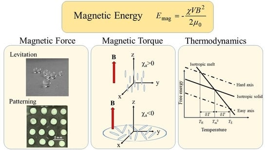
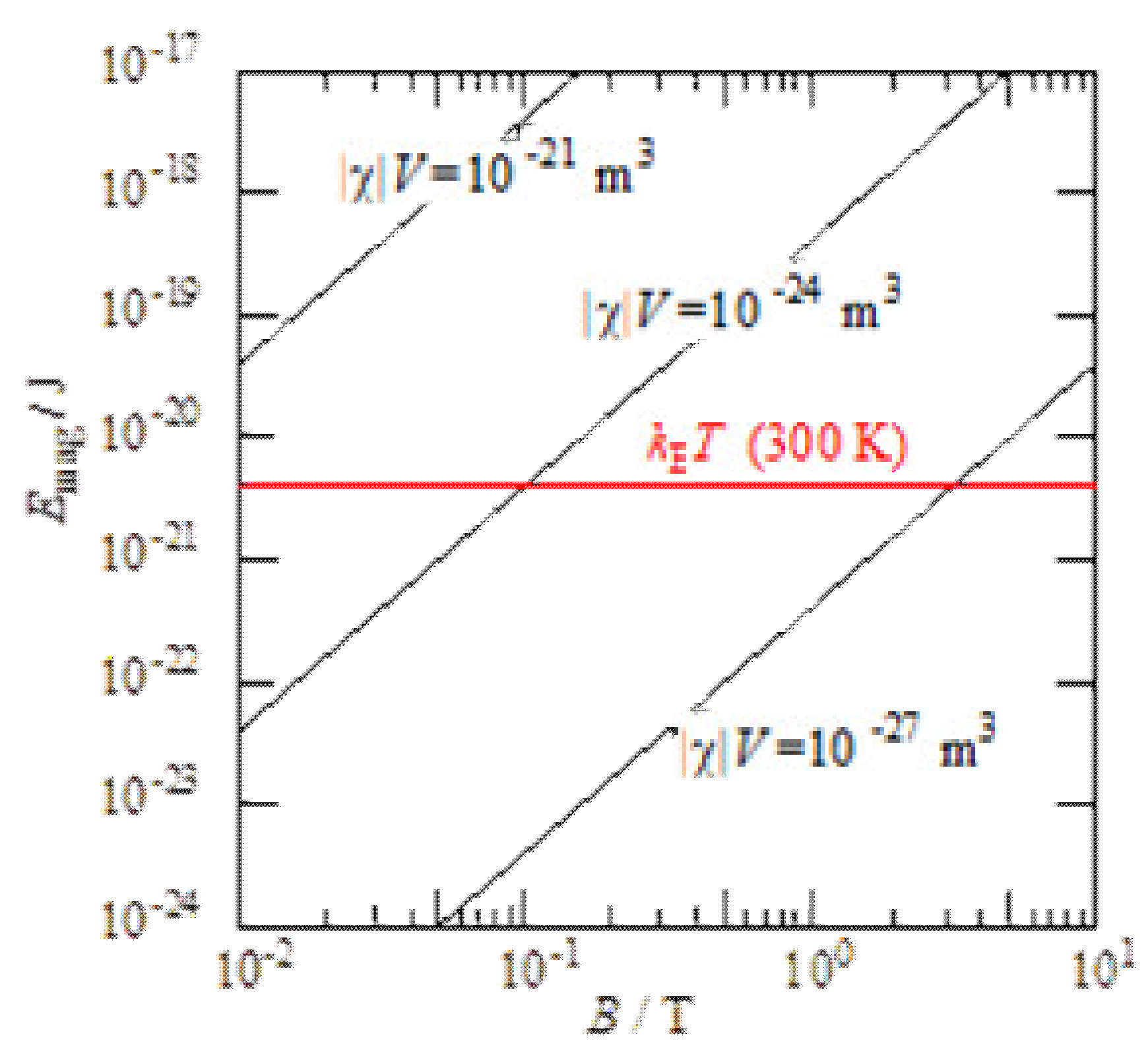
2. Magnetic Energy
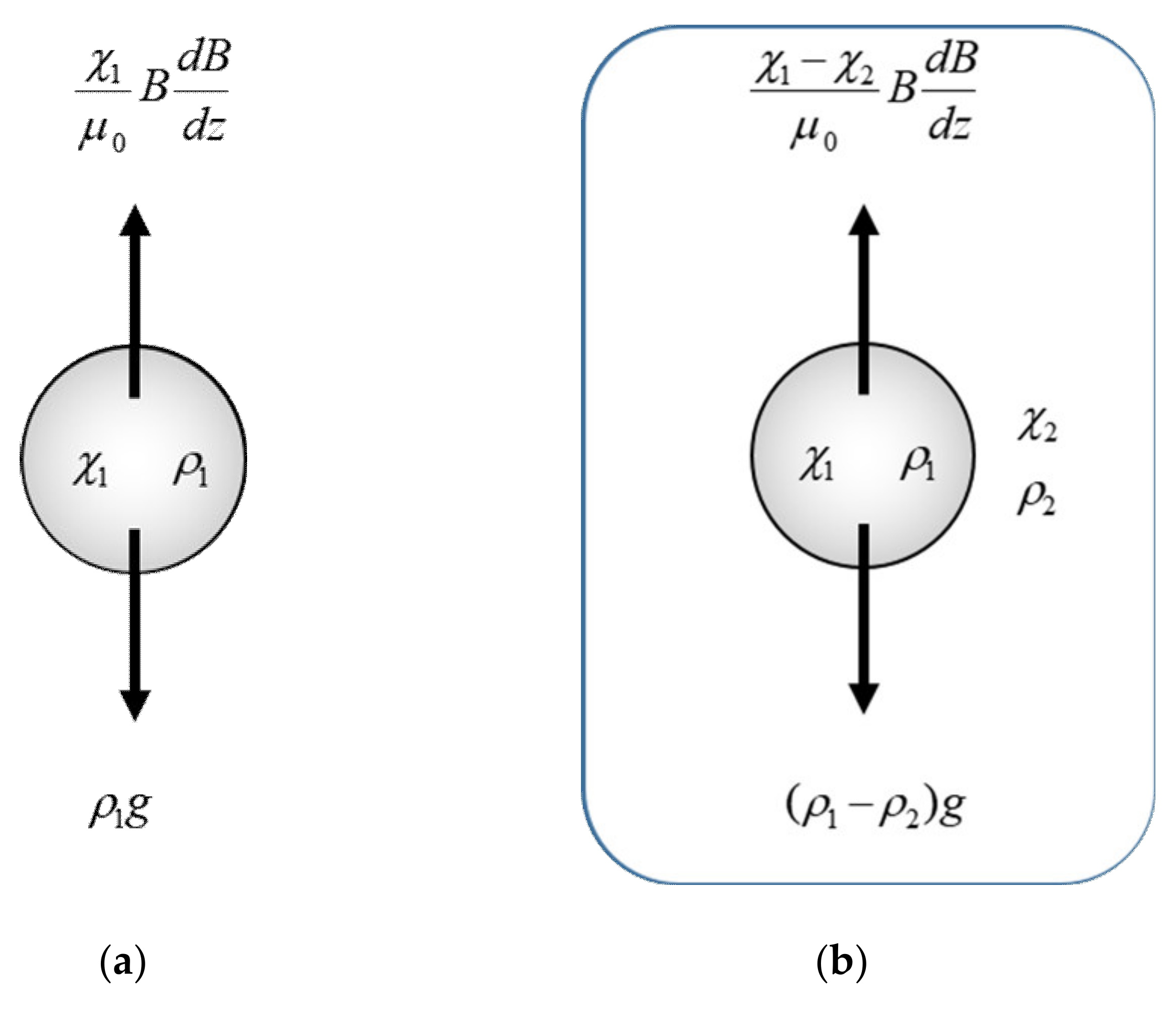
3. Magnetic Force
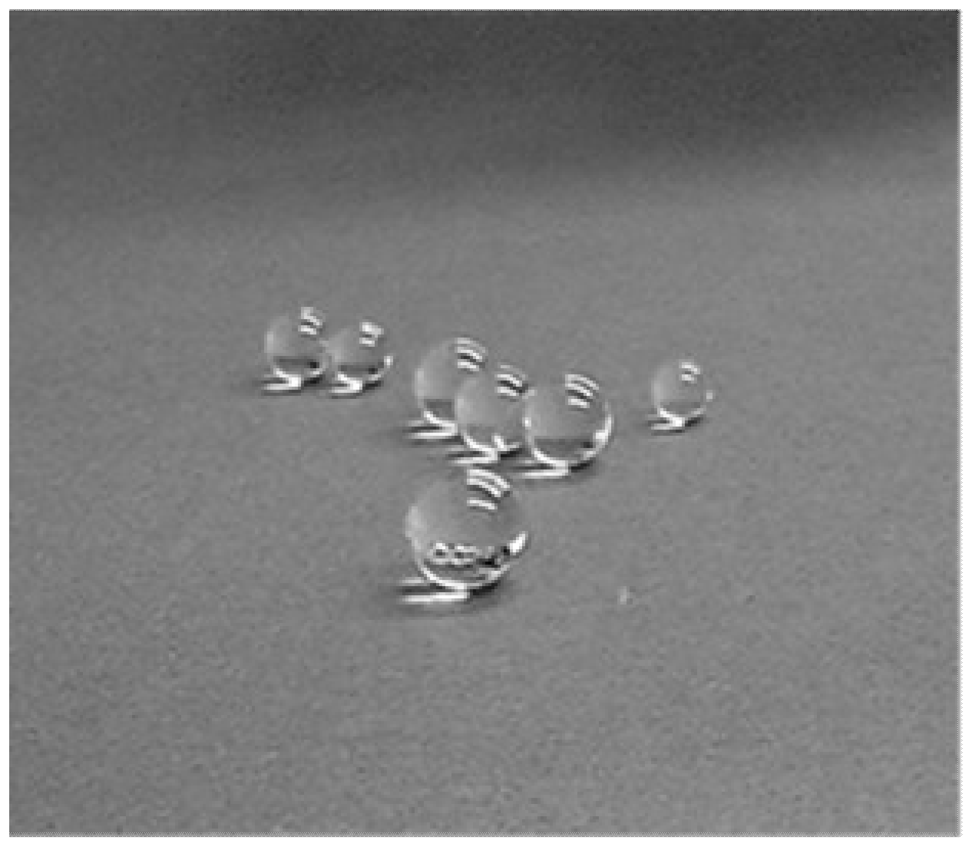
3.1. Levitation
3.2. Separation
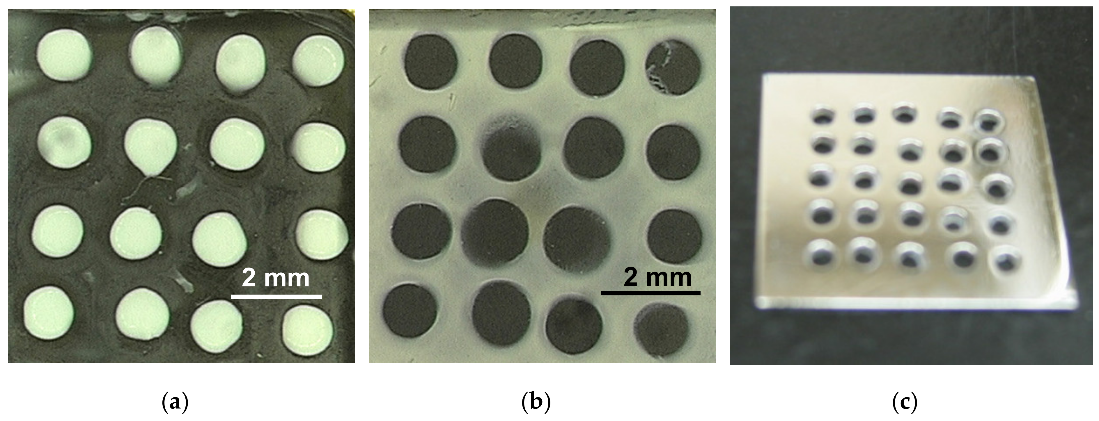
3.3. Particle Manipulation and Patterning
3.4. Crystallization Under Levitation
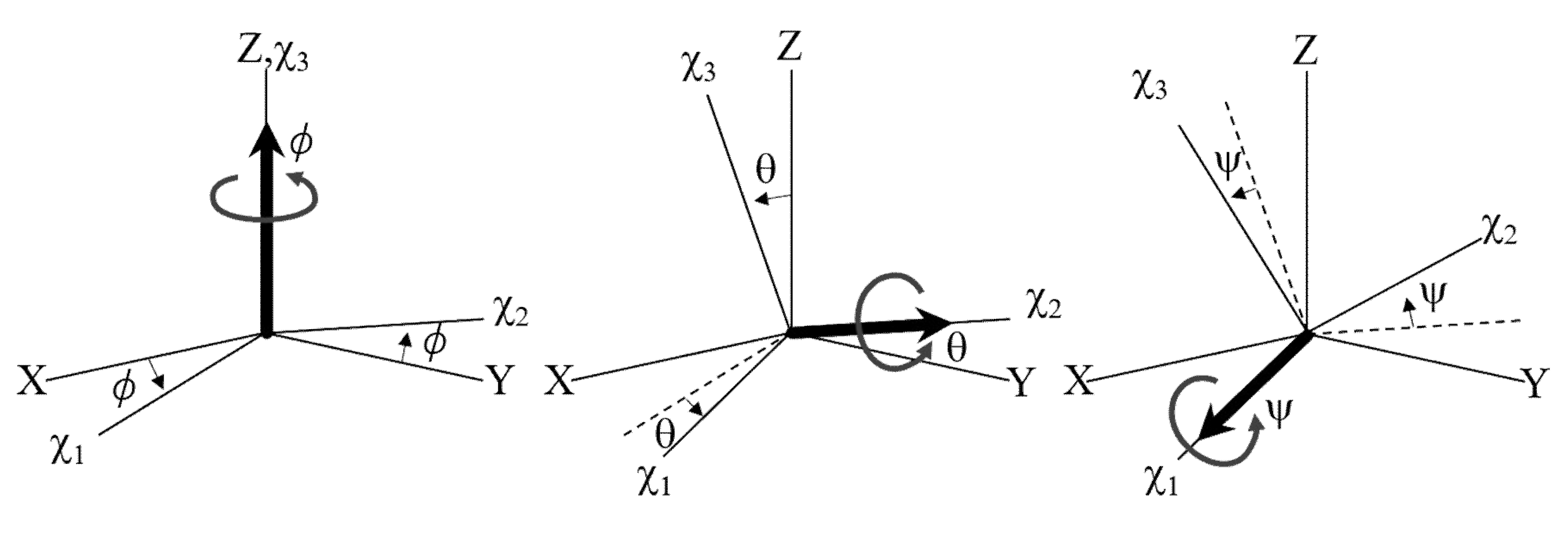
4. Magnetic Torque
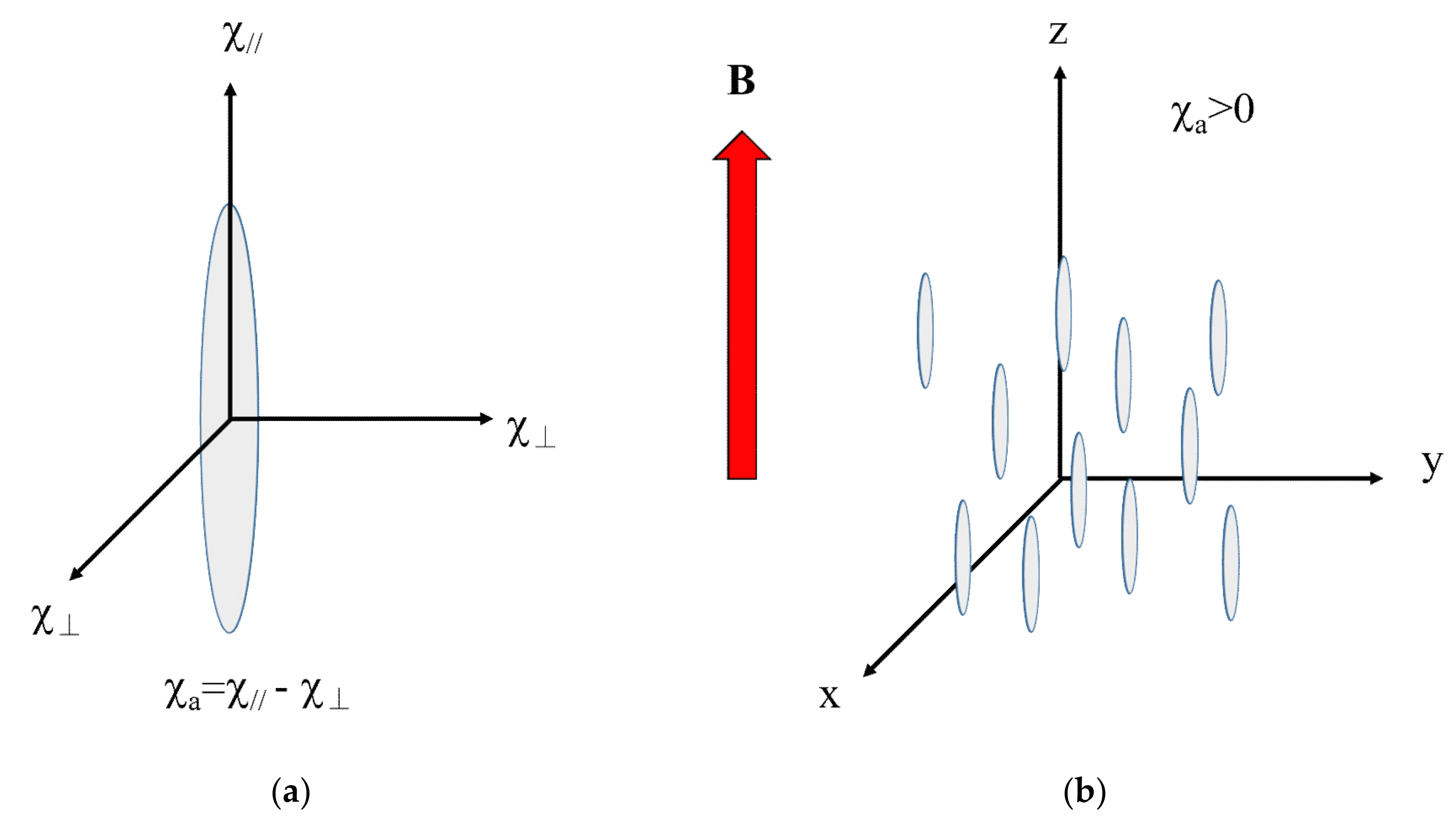
4.1. Magnetic Anisotropy
4.2. Anisotropic Magnetic Energy
4.3. Magnetic Orientation of Uniaxial Particles
4.4. Magnetic Orientation of Biaxial Crystals
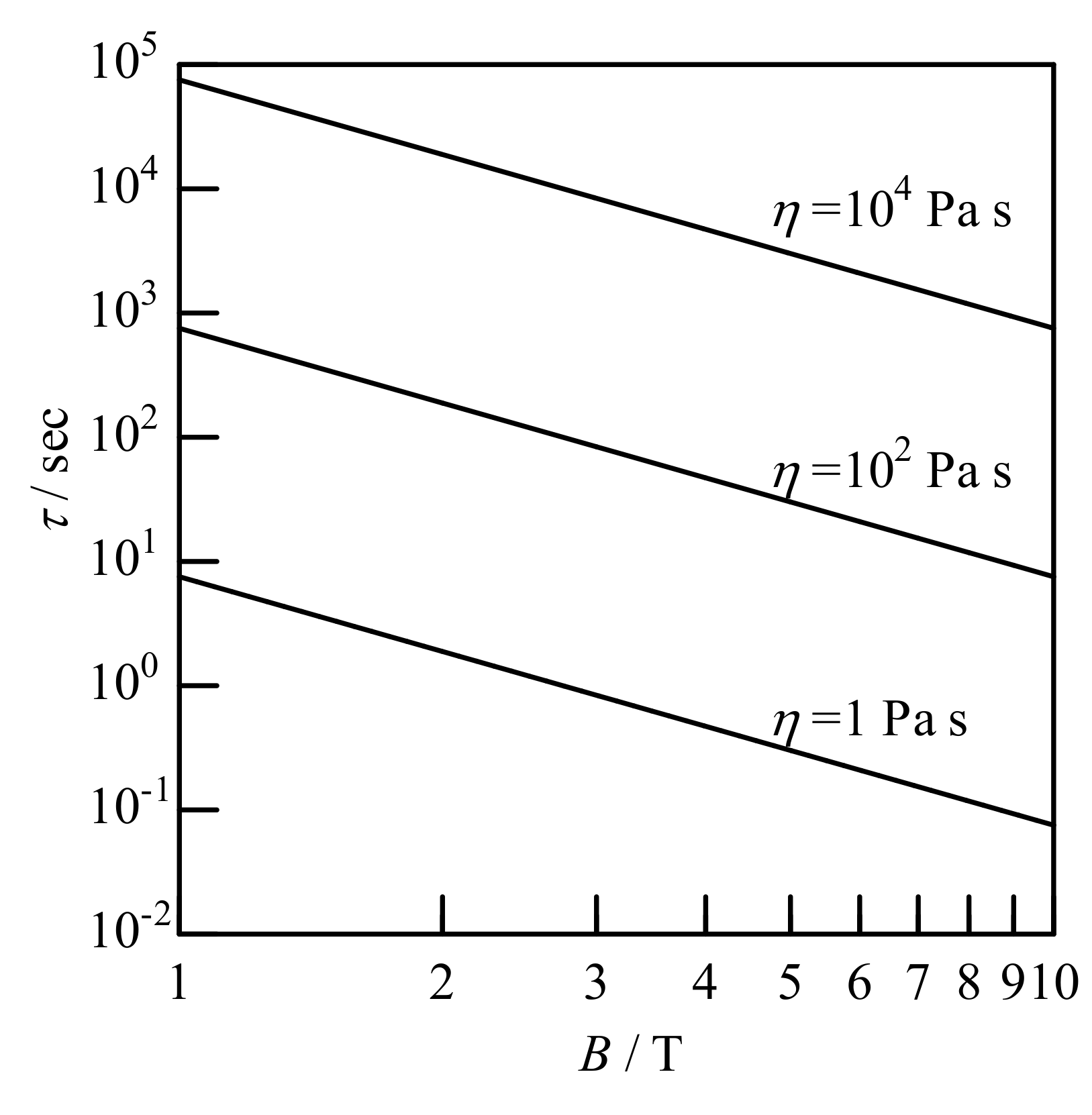
4.5. Alignment Kinetics
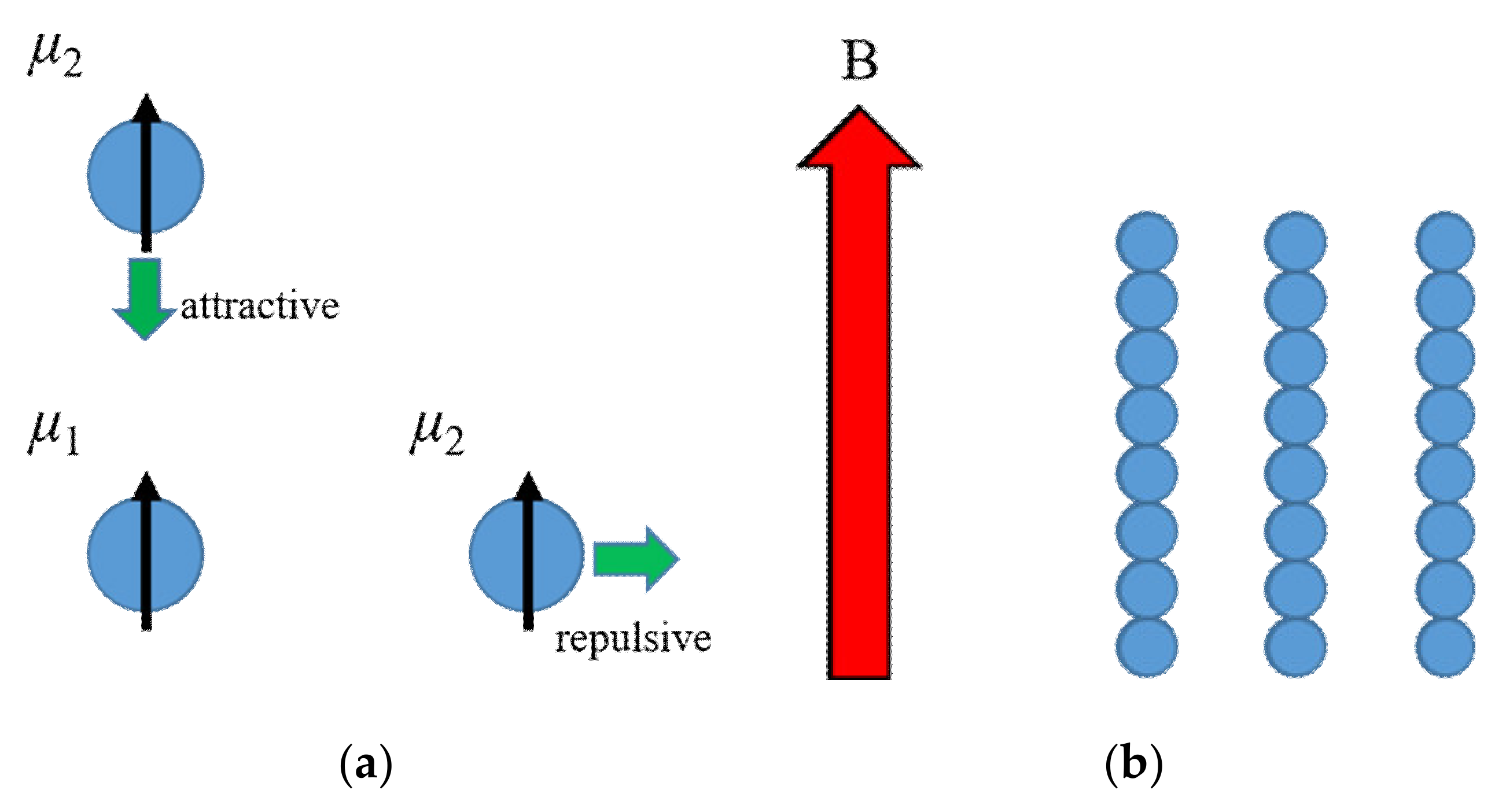
5. Magnetic Dipole–Dipole Interaction
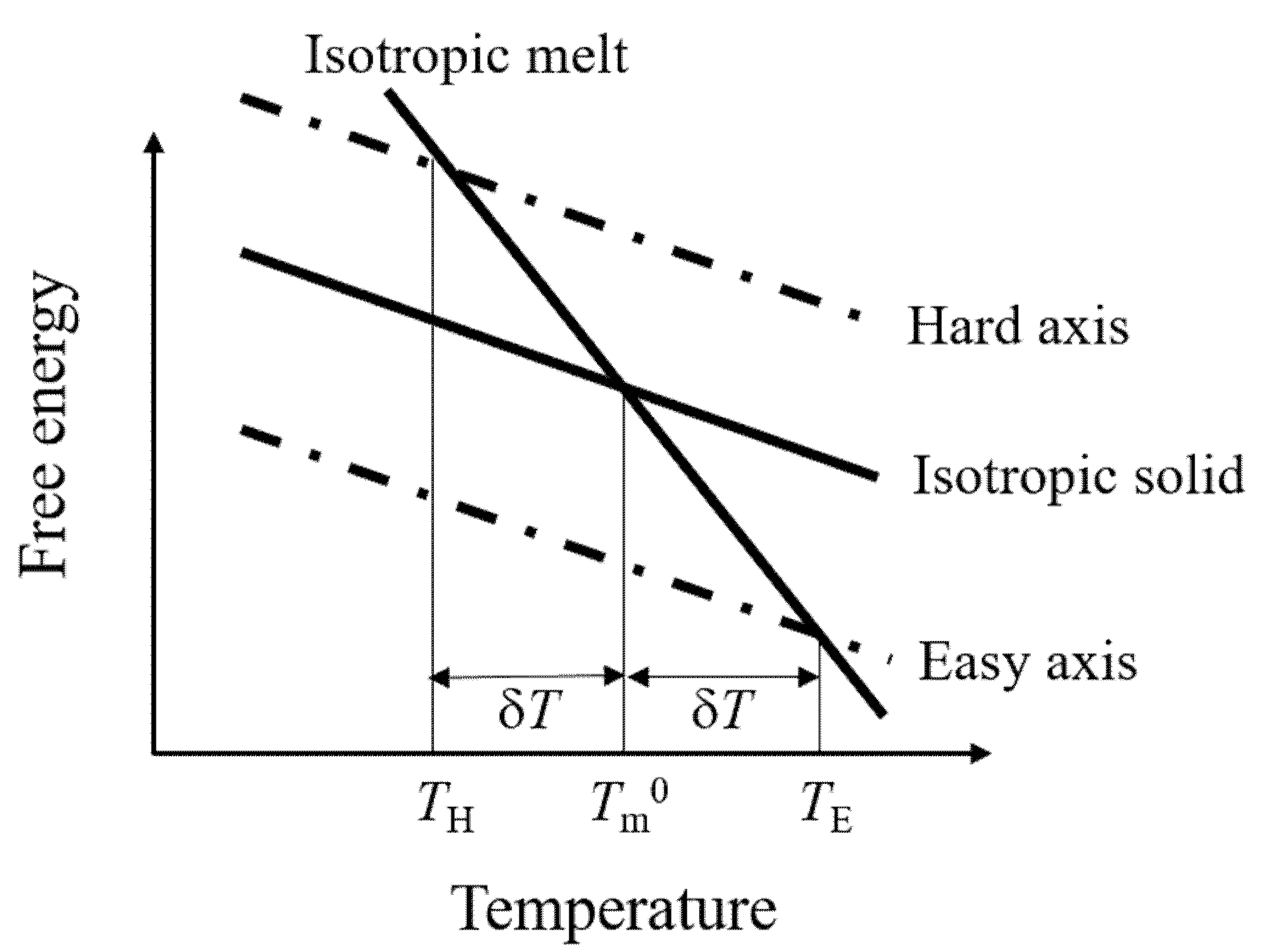
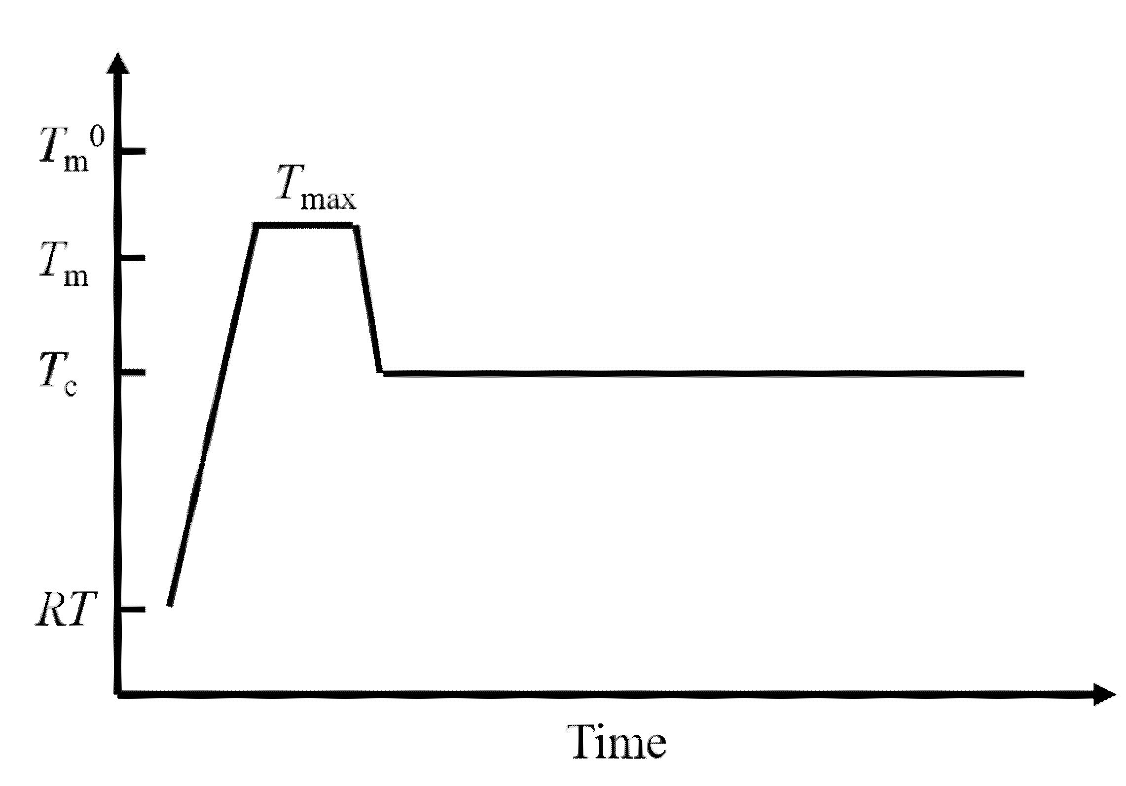
6. Thermodynamics: Phase Transition Temperature
7. Magnetic Orientation of Crystalline Polymers
8. Magnetic Orientation of Microphase-Separated Structure
9. Conclusions
Author Contributions
Funding
Acknowledgments
Conflicts of Interest
References
- Van Vleck, J.H. The Classical Theory of Magnetic Susceptibilities. In The Theory of Electric and Magnetic Susceptibilities; Oxford University Press: London, UK, 1932; pp. 91–94. [Google Scholar]
- Wagner, D. Diamagnetism. In Introduction to the Theory of Magnetism; Pergamon Press: Oxford, UK, 1972; pp. 6–8. [Google Scholar]
- Gupta, R.R. Semiempirical calculation of diamagnetic susceptibilities of organo-silicon compounds containing carbon-silicon bonds. J. Chem. Phys. 1977, 67, 3298–3299. [Google Scholar] [CrossRef]
- Maret, G.; Schickfus, M.v.; Mayer, A.; Dransfeld, K. Orientation of Nucleic Acids in High Magnetic Fields. Phys. Rev. Lett. 1975, 35, 397–400. [Google Scholar] [CrossRef]
- Beaugnon, E.; Tournier, R. Levitation of organic materials. Nature 1991, 349, 470. [Google Scholar] [CrossRef]
- Motokawa, M.; Hamai, M.; Sato, T.; Mogi, I.; Awaji, S.; Watanabe, K.; Kitamura, N.; Makihara, M. Magnetic levitation experiments in Tohoku University. Phys. B Condens. Matter 2001, 294–295, 729–735. [Google Scholar] [CrossRef]
- Simon, M.D.; Geim, A.K. Diamagnetic levitation: Flying frogs and floating magnets (invited). J. Appl. Phys. 2000, 87, 6200–6204. [Google Scholar] [CrossRef]
- Hirota, N.; Homma, T.; Sugawara, H.; Kitazawa, K.; Iwasaka, M.; Ueno, S.; Yokoi, H.; Kakudate, Y.; Fujiwara, S.; Kawamura, M. Rise and fall of surface level of water solutions under high magnetic field. Jpn. J. Appl. Phys. Part 2 Lett. 1995, 34, L991–L993. [Google Scholar] [CrossRef]
- Yamaguchi, M.; Tanimoto, Y. (Eds.) Magneto-Science: Magnetic Field Effects on Materials: Fundamentals and Applications; Springer: Berlin/Heidelberg, Germany, 2006. [Google Scholar]
- Hayashi, H. Introduction to Dynamic Spin Chemistry Magnetic Field Effects of Chemical and Biochemical Reactions; World Scientific Publishing Co.Pte. Ltd: Singapore, 2004; ISBN 9812384235. [Google Scholar]
- Sakaguchi, A.; Hamasaki, A.; Ozeki, S. Colloid and Interface Chemistry under Magnetic Fields. Chem. Lett. 2012, 41, 342–348. [Google Scholar] [CrossRef]
- Shoogo, U.; Masaki, S. (Eds.) Biomagnetics: Principles and Applications of Biomagnetic Stimulation and Imaging; CRC Press: Boca Raton, FL, USA, 2016. [Google Scholar]
- Kimura, T. Study on the effect of magnetic fields on polymeric materials and its application. Polym. J. (Tokyo, Japan) 2003, 35, 823–843. [Google Scholar] [CrossRef]
- Hu, H.; Gopinadhan, M.; Osuji, C.O. Directed self-assembly of block copolymers: A tutorial review of strategies for enabling nanotechnology with soft matter. Soft Matter 2014, 10, 3867. [Google Scholar] [CrossRef]
- Kimura, T. Magnetic Processing of Feeble Magnetic Materials under High Magnetic Fields. Magn. Jpn. 2009, 4, 516–523. (In Japaneas) [Google Scholar]
- Mitsumata, T.; Honda, A.; Kanazawa, H.; Kawai, M. Magnetically Tunable Elasticity for Magnetic Hydrogels Consisting of Carrageenan and Carbonyl Iron Particles. J. Phys. Chem. B 2012, 116, 12341–12348. [Google Scholar] [CrossRef] [PubMed]
- Yamaguchi, M.; Ozawa, S.; Yamamoto, I. Rotational Diffusion Model of Magnetic Alignment. Jpn. J. Appl. Phys. 2009, 48, 063001. [Google Scholar] [CrossRef]
- Motokawa, M. Magnetic Levitation. In Materials Science in Static High Magnetic Fields; Watanabe, K., Motokawa, M., Eds.; Springer-Verlag: Berlin/Heidelberg, Germany, 2002; pp. 263–282. [Google Scholar]
- Ge, S.; Semenov, S.N.; Nagarkar, A.A.; Milette, J.; Christodouleas, D.C.; Yuan, L.; Whitesides, G.M. Magnetic Levitation To Characterize the Kinetics of Free-Radical Polymerization. J. Am. Chem. Soc. 2017, 139, 18688–18697. [Google Scholar] [CrossRef] [PubMed]
- Ilievski, F.; Mirica, K.A.; Ellerbee, A.K.; Whitesides, G.M. Templated self-assembly in three dimensions using magnetic levitation. Soft Matter 2011, 7, 9113. [Google Scholar] [CrossRef]
- Tanimoto, Y.; Fujiwara, M.; Sueda, M.; Inoue, K.; Akita, M. Magnetic Levitation of Plastic Chips: Applications for Magnetic Susceptibility Measurement and Magnetic Separation. Jpn. J. Appl. Phys. 2005, 44, 6801–6803. [Google Scholar] [CrossRef]
- Berry, M.V.; Geim, A.K. Of flying frogs and levitrons. Eur. J. Phys. 1997, 18, 307–313. [Google Scholar] [CrossRef]
- Catherall, A.T.; Eaves, L.; King, P.J.; Booth, S.R. Floating gold in cryogenic oxygen. Nature 2003, 422, 579. [Google Scholar] [CrossRef]
- Ikezoe, Y.; Hirota, N.; Nakagawa, J.; Kitazawa, K. Making water levitate. Nature 1998, 393, 749–750. [Google Scholar] [CrossRef]
- Ikezoe, Y.; Kaihatsu, T.; Uetake, H.; Hirota, N.; Nakagawa, J.; Kitazawa, K. Stable levitation of water by magneto-Archimedes principle. Trans. Mater. Res. Soc. Japan 2000, 25, 77–80. [Google Scholar]
- Mirica, K.A.; Phillips, S.T.; Mace, C.R.; Whitesides, G.M. Magnetic Levitation in the Analysis of Foods and Water. J. Agric. Food Chem. 2010, 58, 6565–6569. [Google Scholar] [CrossRef]
- Kitamura, N.; Makihara, M.; Hamai, M.; Sato, T.; Mogi, I.; Awaji, S.; Watanabe, K.; Motokawa, M. Containerless Melting of Glass by Magnetic Levitation Method. Jpn. J. Appl. Phys. 2000, 39, L324–L326. [Google Scholar] [CrossRef]
- Yamato, M.; Nakazawa, H.; Kimura, T. Levitation Polymerization to Fabricate a Large Polymer Sphere. Langmuir 2002, 18, 9609–9610. [Google Scholar] [CrossRef]
- Kimura, T.; Mamada, S.; Yamato, M. Separation of Solid Polymers by Magneto-Archimedes Levitation. Chem. Lett. 2000, 29, 1294–1295. [Google Scholar] [CrossRef]
- Ueda, Y.; Mishima, F.; Akiyama, Y.; Nishijima, S. Fundamental Study of Plastic Separation Utilizing Magnetic Force. IEEE Trans. Appl. Supercond. 2014, 24, 1–5. [Google Scholar] [CrossRef]
- Winkleman, A.; Perez-Castillejos, R.; Gudiksen, K.L.; Phillips, S.T.; Prentiss, M.; Whitesides, G.M. Density-based diamagnetic separation: Devices for detecting binding events and for collecting unlabeled diamagnetic particles in paramagnetic solutions. Anal. Chem. 2007, 79, 6542–6550. [Google Scholar] [CrossRef] [PubMed]
- Iranmanesh, M.; Hulliger, J. Magnetic separation: Its application in mining, waste purification, medicine, biochemistry and chemistry. Chem. Soc. Rev. 2017, 46, 5925–5934. [Google Scholar] [CrossRef] [PubMed]
- Maki, S.; Hirota, N. Magnetic separation technique on binary mixtures of sorbitol and sucrose. J. Food Eng. 2014, 120, 31–36. [Google Scholar] [CrossRef]
- Atkinson, M.B.J.; Bwambok, D.K.; Chen, J.; Chopade, P.D.; Thuo, M.M.; Mace, C.R.; Mirica, K.A.; Kumar, A.A.; Myerson, A.S.; Whitesides, G.M. Using Magnetic Levitation to Separate Mixtures of Crystal Polymorphs. Angew. Chemie Int. Ed. 2013, 52, 10208–10211. [Google Scholar] [CrossRef]
- Yang, X.; Wong, S.Y.; Bwambok, D.K.; Atkinson, M.B.J.; Zhang, X.; Whitesides, G.M.; Myerson, A.S. Separation and enrichment of enantiopure from racemic compounds using magnetic levitation. Chem. Commun. 2014, 50, 7548–7551. [Google Scholar] [CrossRef]
- Hennek, J.W.; Nemiroski, A.; Subramaniam, A.B.; Bwambok, D.K.; Yang, D.; Harburg, D.V.; Tricard, S.; Ellerbee, A.K.; Whitesides, G.M. Using Magnetic Levitation for Non-Destructive Quality Control of Plastic Parts. Adv. Mater. 2015, 27, 1587–1592. [Google Scholar] [CrossRef]
- Mirica, K.A.; Ilievski, F.; Ellerbee, A.K.; Shevkoplyas, S.S.; Whitesides, G.M. Using Magnetic Levitation for Three Dimensional Self-Assembly. Adv. Mater. 2011, 23, 4134–4140. [Google Scholar] [CrossRef] [PubMed]
- Ge, S.; Whitesides, G.M. “Axial” Magnetic Levitation Using Ring Magnets Enables Simple Density-Based Analysis, Separation, and Manipulation. Anal. Chem. 2018, 90, 12239–12245. [Google Scholar] [CrossRef] [PubMed]
- Kimura, T.; Yamato, M.; Nara, A. Particle Trapping and Undulation of a Liquid Surface Using a Microscopically Modulated Magnetic Field. Langmuir 2004, 20, 572–574. [Google Scholar] [CrossRef] [PubMed]
- Subramaniam, A.B.; Yang, D.; Yu, H.-D.; Nemiroski, A.; Tricard, S.; Ellerbee, A.K.; Soh, S.; Whitesides, G.M. Noncontact orientation of objects in three-dimensional space using magnetic levitation. Proc. Natl. Acad. Sci. USA 2014, 111, 12980–12985. [Google Scholar] [CrossRef]
- Winkleman, A.; Gudiksen, K.L.; Ryan, D.; Whitesides, G.M.; Greenfield, D.; Prentiss, M. A magnetic trap for living cells suspended in a paramagnetic buffer. Appl. Phys. Lett. 2004, 85, 2411–2413. [Google Scholar] [CrossRef]
- Kimura, T.; Sato, Y.; Kimura, F.; Iwasaka, M.; Ueno, S. Micropatterning of Cells Using Modulated Magnetic Fields. Langmuir 2005, 21, 830–832. [Google Scholar] [CrossRef]
- Wakayama, N.I.; Ataka, M.; Abe, H. Effect of a magnetic field gradient on the crystallization of hen lysozyme. J. Cryst. Growth 1997, 178, 653–656. [Google Scholar] [CrossRef]
- Lin, S.-X.; Zhou, M.; Azzi, A.; Xu, G.-J.; Wakayama, N.I.; Ataka, M. Magnet Used for Protein Crystallization: Novel Attempts to Improve the Crystal Quality. Biochem. Biophys. Res. Commun. 2000, 275, 274–278. [Google Scholar] [CrossRef]
- Sazaki, G. Crystal quality enhancement by magnetic fields. Prog. Biophys. Mol. Biol. 2009, 101, 45–55. [Google Scholar] [CrossRef]
- Nakamura, A.; Ohtsuka, J.; Miyazono, K.; Yamamura, A.; Kubota, K.; Hirose, R.; Hirota, N.; Ataka, M.; Sawano, Y.; Tanokura, M. Improvement in Quality of Protein Crystals Grown in a High Magnetic Field Gradient. Cryst. Growth Des. 2012, 12, 1141–1150. [Google Scholar] [CrossRef]
- Chernov, A.A. Modern Crystallography III Crystal Growth; Springer-Verlag: Berlin, Germany, 1984. [Google Scholar]
- Nakada, T.; Sazaki, G.; Miyashita, S.; Durbin, S.D.; Komatsu, H. Direct AFM observations of impurity effects on a lysozyme crystal. J. Cryst. Growth 1999, 196, 503–510. [Google Scholar] [CrossRef]
- Dold, P.; Ono, E.; Tsukamoto, K.; Sazaki, G. Step velocity in tetragonal lysozyme growth as a function of impurity concentration and mass transport conditions. J. Cryst. Growth 2006, 293, 102–109. [Google Scholar] [CrossRef]
- McPherson, A.; DeLucas, L.J. Microgravity protein crystallization. NPJ Microgravity 2015, 1, 15010. [Google Scholar] [CrossRef]
- Nakamura, A.; Ohtsuka, J.; Kashiwagi, T.; Numoto, N.; Hirota, N.; Ode, T.; Okada, H.; Nagata, K.; Kiyohara, M.; Suzuki, E.; et al. In-situ and real-time growth observation of high-quality protein crystals under quasi-microgravity on earth. Sci. Rep. 2016, 6, 22127. [Google Scholar] [CrossRef] [PubMed]
- Weiss, A.; Witte, H. Magnetochemie; Verlag Chemie GmbH: Weinheim/Bergstr, Germany, 1973; (Japanease Translation). [Google Scholar]
- Yamato, M.; Aoki, H.; Kimura, T.; Yamamoto, I.; Ishikawa, F.; Yamaguchi, M.; Tobita, M. Determination of anisotropic diamagnetic susceptibility of polymeric fibers suspended in liquid. Jpn. J. Appl. Phys. Part 1 Regul. Pap. Short Notes Rev. Pap. 2001, 40, 2237–2240. [Google Scholar] [CrossRef]
- Sugiyama, J.; Chanzy, H.; Maret, G. Orientation of cellulose microcrystals by strong magnetic fields. Macromolecules 1992, 25, 4232–4234. [Google Scholar] [CrossRef]
- Frka-Petesic, B.; Sugiyama, J.; Kimura, S.; Chanzy, H.; Maret, G. Negative Diamagnetic Anisotropy and Birefringence of Cellulose Nanocrystals. Macromolecules 2015, 48, 8844–8857. [Google Scholar] [CrossRef]
- Nye, J.F. Physical Properties of Crystals: Their Representation by Tensors and Matrices; Clarendon Press: Oxford, UK, 1985. [Google Scholar]
- Kimura, F.; Kimura, T. Magnetically textured powders—An alternative to single-crystal and powder X-ray diffraction methods. CrystEngComm 2018, 20, 861–872. [Google Scholar] [CrossRef]
- Takahashi, T.; Murayama, T.; Higuchi, A.; Awano, H.; Yonetake, K. Aligning vapor-grown carbon fibers in polydimethylsiloxane using dc electric or magnetic field. Carbon N. Y. 2006, 44, 1180–1188. [Google Scholar] [CrossRef]
- Piao, G.; Kimura, F.; Takahashi, T.; Moritani, Y.; Awano, H.; Nimori, S.; Tsuda, K.; Yonetake, K.; Kimura, T. Alignment and Micropatterning of Carbon Nanotubes in Polymer Composites Using Modulated Magnetic Field. Polym. J. 2007, 39, 589–592. [Google Scholar] [CrossRef]
- Lv, F.; Xu, L.; Xu, Z.; Fu, L.; Zhang, Y. Fabrication and characterization of the orientated MMT/PI composite films via relatively low magnetic field. J. Appl. Polym. Sci. 2015, 132, 41224/1–41224/8. [Google Scholar] [CrossRef]
- Ma, C.; Liu, H.-Y.; Du, X.; Mach, L.; Xu, F.; Mai, Y.-W. Fracture resistance, thermal and electrical properties of epoxy composites containing aligned carbon nanotubes by low magnetic field. Compos. Sci. Technol. 2015, 114, 126–135. [Google Scholar] [CrossRef]
- Ciambella, J.; Stanier, D.C.; Rahatekar, S.S. Magnetic alignment of short carbon fibres in curing composites. Compos. Part B Eng. 2017, 109, 129–137. [Google Scholar] [CrossRef]
- Pelligra, C.I.; Majewski, P.W.; Osuji, C.O. Large area vertical alignment of ZnO nanowires in semiconducting polymer thin films directed by magnetic fields. Nanoscale 2013, 5, 10511. [Google Scholar] [CrossRef]
- Mauter, M.S.; Elimelech, M.; Osuji, C.O. Nanocomposites of Vertically Aligned Single-Walled Carbon Nanotubes by Magnetic Alignment and Polymerization of a Lyotropic Precursor. ACS Nano 2010, 4, 6651–6658. [Google Scholar] [CrossRef] [PubMed]
- Kawai, T.; Iijima, R.; Yamamoto, Y.; Kimura, T. Crystal orientation of β-phase isotactic polypropylene induced by magnetic orientation of N,N′-dicyclohexyl-2,6-naphthalenedicarboxamide. Polymer (Guildf) 2002, 43, 7301–7306. [Google Scholar] [CrossRef]
- Takahashi, T.; Higuchi, A.; Awano, H.; Yonetake, K.; Kikuchi, T. Oriented Crystallization of Polycarbonate by Vapor Grown Carbon Fiber and its Application. Polym. J. 2005, 37, 887–893. [Google Scholar] [CrossRef][Green Version]
- Yamato, M.; Kudo, Y.; Takahashi, K.; Watanabe, K.; Kawamoto, N. Magnetic Alignment of Poly(L-lactic acid) Containing a Nucleating Agent. Chem. Lett. 2011, 40, 765–767. [Google Scholar] [CrossRef]
- Timbrell, V. Alignment of carbon and other man-made fibers by magnetic fields. J. Appl. Phys. 1972, 43, 4839–4840. [Google Scholar] [CrossRef]
- Fujiwara, M.; Oki, E.; Hamada, M.; Tanimoto, Y.; Mukouda, I.; Shimomura, Y. Magnetic Orientation and Magnetic Properties of a Single Carbon Nanotube. J. Phys. Chem. A 2001, 105, 4383–4386. [Google Scholar] [CrossRef]
- Choi, E.S.; Brooks, J.S.; Eaton, D.L.; Al-Haik, M.S.; Hussaini, M.Y.; Garmestani, H.; Li, D.; Dahmen, K. Enhancement of thermal and electrical properties of carbon nanotube polymer composites by magnetic field processing. J. Appl. Phys. 2003, 94, 6034–6039. [Google Scholar] [CrossRef]
- Goetz, A. Production of “colloidal single crystals”. Phys. Rev. 1934, 45, 282–283. [Google Scholar] [CrossRef]
- Kim, J.E.; Han, T.H.; Lee, S.H.; Kim, J.Y.; Ahn, C.W.; Yun, J.M.; Kim, S.O. Graphene oxide liquid crystals. Angew. Chemie Int. Ed. 2011, 50, 3043–3047. [Google Scholar] [CrossRef]
- Wu, L.; Ohtani, M.; Takata, M.; Saeki, A.; Seki, S.; Ishida, Y.; Aida, T. Magnetically Induced Anisotropic Orientation of Graphene Oxide Locked by in Situ Hydrogelation. ACS Nano 2014, 8, 4640–4649. [Google Scholar] [CrossRef] [PubMed]
- Tobita, M.; Tateda, S.; Kimura, T.; Yamato, M. Magnetically oriented boron nitride-filled highly thermally conductive sheet. Jpn. Kokai Tokkyo Koho 2002, 10. [Google Scholar]
- Suzuki, T.S.; Uchikoshi, T.; Sakka, Y. Effect of sintering additive on crystallographic orientation in AlN prepared by slip casting in a strong magnetic field. J. Eur. Ceram. Soc. 2009, 29, 2627–2633. [Google Scholar] [CrossRef]
- Uyeda, C.; Takeuchi, T.; Yamagishi, A.; Tsuchiyama, A.; Yamanaka, T.; Date, M. Diamagnetic anisotropy of sheetsilicates. Phys. Chem. Miner. 1993, 20, 369–374. [Google Scholar] [CrossRef]
- Takahashi, T.; Ohkubo, T.; Ikeda, Y. Montmorillonite alignment induced by magnetic field: Evidence based on the diffusion anisotropy of water molecules. J. Colloid Interface Sci. 2006, 299, 198–203. [Google Scholar] [CrossRef]
- Kitajima, S.; Matsuda, M.; Yamato, M.; Tominaga, Y. Anisotropic ionic conduction in composite polymer electrolytes filled with clays oriented by a strong magnetic field. Polym. J. 2013, 45, 738–743. [Google Scholar] [CrossRef]
- Uyeda, C.; Takeuchi, T.; Yamagishi, A.; Date, M. Diamagnetic orientation of clay mineral grains. J. Phys. Soc. Japan 1991, 60, 3234–3237. [Google Scholar] [CrossRef]
- Abrahamsson, C.; Nordstierna, L.; Nordin, M.; Dvinskikh, S.V.; Nyden, M.; Nydén, M. Magnetic orientation of nontronite clay in aqueous dispersions and its effect on water diffusion. J. Colloid Interface Sci. 2015, 437, 205–210. [Google Scholar] [CrossRef] [PubMed]
- Liu, M.; Ishida, Y.; Ebina, Y.; Sasaki, T.; Hikima, T.; Takata, M.; Aida, T. An anisotropic hydrogel with electrostatic repulsion between cofacially aligned nanosheets. Nature 2015, 517, 68–72. [Google Scholar] [CrossRef]
- Nakayama, M.; Kajiyama, S.; Kumamoto, A.; Nishimura, T.; Ikuhara, Y.; Yamato, M.; Kato, T. Stimuli-responsive hydroxyapatite liquid crystal with macroscopically controllable ordering and magneto-optical functions. Nat. Commun. 2018, 9, 568. [Google Scholar] [CrossRef]
- Matsunaga, C.; Uchikoshi, T.; Suzuki, T.S.; Sakka, Y.; Matsuda, M. Orientation control of mordenite zeolite in strong magnetic field. Microporous Mesoporous Mater. 2012, 151, 188–194. [Google Scholar] [CrossRef]
- Miwa, Y.; Kawada, S.; Kimura, M.; Omiya, S.; Kubodera, N.; Ando, A.; Suzuki, T.S.; Uchikoshi, T.; Sakka, Y. Processing and enhanced piezoelectric properties of highly oriented compositionally modified Pb(Zr,Ti)O3 ceramics fabricated by magnetic alignment. Appl. Phys. Express 2015, 8, 1–4. [Google Scholar] [CrossRef]
- Kimura, T.; Yoshino, M.; Yamane, T.; Yamato, M.; Tobita, M. Uniaxial alignment of the smallest diamagnetic susceptibility axis using time-dependent magnetic fields. Langmuir 2004, 20, 5669–5672. [Google Scholar] [CrossRef]
- Genoud, J.-Y.; Staines, M.; Mawdsley, A.; Manojlovic, V.; Quinton, W. Biaxially textured YBCO coated tape prepared using dynamic magnetic grain alignment. Supercond. Sci. Technol. 1999, 12, 663–671. [Google Scholar] [CrossRef]
- Kimura, T.; Yoshino, M. Three-dimensional crystal alignment using a time-dependent elliptic magnetic field. Langmuir 2005, 21, 4805–4808. [Google Scholar] [CrossRef]
- Kimura, T.; Kimura, F.; Yoshino, M. Magnetic alteration of crystallite alignment converting powder to a pseudo single crystal. Langmuir 2006, 22, 3464–3466. [Google Scholar] [CrossRef]
- Horii, S.; Yamaki, M.; Shimoyama, J. Rare-Earth-Dependent Tri-axial Magnetic Anisotropies and Growth Conditions in REBa 2 Cu 4 O 8 Related content Growth of (Y1xCax)Ba2Cu4O8 in ambient pressure and its tri-axial magnetic alignment. Jpn. J. Appl. Phys. 2012, 51, 010107/1–010107/7. [Google Scholar] [CrossRef]
- Nakatsuka, N.; Yasuda, H.; Nagira, T.; Yoshiya, M. Three-dimensional alignment of FeSi2 with orthorhombic symmetry by an anisotropic magnetic field. J. Phys. Conf. Ser. 2009, 165, 012021. [Google Scholar] [CrossRef]
- Kimura, F.; Oshima, W.; Matsumoto, H.; Uekusa, H.; Aburaya, K.; Maeyama, M.; Kimura, T. Single crystal structure analysis via magnetically oriented microcrystal arrays. CrystEngComm 2014, 16, 6630–6634. [Google Scholar] [CrossRef]
- Kusumi, R.; Kimura, F.; Song, G.; Kimura, T. Chemical shift tensor determination using magnetically oriented microcrystal array (MOMA): 13C solid-state CP NMR without MAS. J. Magn. Reson. 2012, 223, 68–72. [Google Scholar] [CrossRef]
- Teranishi, S.; Kusumi, R.; Kimura, F.; Kimura, T.; Aburaya, K.; Maeyama, M. Biaxial magnetic orientation of zinc citrate as nucleating agent of poly(L-lactic acid). Chem. Lett. 2017, 46, 830–832. [Google Scholar] [CrossRef]
- Horii, S.; Arimoto, I.; Doi, T. Linear drive type of modulated rotating magnetic field for a continuous process of three-dimensional crystal orientation. J. Ceram. Soc. Japan 2018, 126, 885–888. [Google Scholar] [CrossRef]
- Moore, J.S.; Stupp, S.I. Orientation dynamics of main-chain liquid crystal polymers. 2. Structure and kinetics in a magnetic field. Macromolecules 1987, 20, 282–293. [Google Scholar] [CrossRef]
- Kimura, T.; Yamato, M.; Koshimizu, W.; Koike, M.; Kawai, T. Magnetic Orientation of Polymer Fibers in Suspension. Langmuir 2000, 16, 858–861. [Google Scholar] [CrossRef]
- Wu, C.; Li, S.; Sassa, K.; Chino, Y.; Hattori, K.; Asai, S. Theoretical Analysis on Crystal Alignment of Feeble Magnetic Materials under High Magnetic Field. Mater. Trans. 2005, 46, 1311–1317. [Google Scholar] [CrossRef]
- Takayama, T.; Ikezoe, Y.; Kaihatsu, T.; Uetake, H.; Hirota, N.; Kitazawa, K. Alignments of feeble magnetic particles under high magnetic fields. Trans. Mater. Res. Soc. Japan 2002, 27, 43–46. [Google Scholar]
- Hirota, N.; Ando, T.; Tanaka, R.; Wada, H.; Sakka, Y. Control of lattice spacing in a triangular lattice of feeble magnetic particles formed by induced magnetic dipole interactions. Sci. Technol. Adv. Mater. 2009, 10, 014608. [Google Scholar] [CrossRef]
- Skjeltorp, A.T. One-and Two-Dimensional Crystallization of Magnetic Holes. Phys. Rev. Lett. 1983, 51, 2306–2309. [Google Scholar] [CrossRef]
- Ando, T.; Hirota, N.; Wada, H. Numerical simulation of chainlike cluster movement of feeble magnetic particles by induced magnetic dipole moment under high magnetic fields. Sci. Technol. Adv. Mater. 2009, 10, 014609. [Google Scholar] [CrossRef]
- Martin, J.E.; Anderson, R.A.; Odinek, J.; Adolf, D.; Williamson, J. Controlling percolation in field-structured particle composites: Observations of giant thermoresistance, piezoresistance, and chemiresistance. Phys. Rev. B 2003, 67, 094207. [Google Scholar] [CrossRef]
- Yamato, M.; Obayashi, S.; Nishiyama, T.; Horibe, H.; Takahashi, K.; Watanabe, K. The effect of the structural order of isotactic polypropylene containing magnetically aligned nickel particles on its electrical resistivity. Polymer (Guildf) 2014, 55, 6546–6551. [Google Scholar] [CrossRef]
- Sun, M.; Dai, B.; Liu, K.; Yao, K.; Zhao, J.; Lyu, Z.; Wang, P.; Ding, Y.; Yang, L.; Han, J.; et al. Enhancement in thermal conductivity of polymer composites using aligned diamonds coated with superparamagnetic magnetite. Compos. Sci. Technol. 2018, 164, 129–135. [Google Scholar] [CrossRef]
- Martin, J.; Venturini, E.; Odinek, J.; Anderson, R. Anisotropic magnetism in field-structured composites. Phys. Rev. E 2000, 61, 2818–2830. [Google Scholar] [CrossRef]
- Chung, J.-Y.; Lee, J.-G.; Baek, Y.-K.; Shin, P.-W.; Kim, Y.-K. Magnetic field-induced enhancement of thermal conductivities in polymer composites by linear clustering of spherical particles. Compos. Part B Eng. 2018, 136, 215–221. [Google Scholar] [CrossRef]
- Li, W.; Yu, L.; Zhu, Y.; Hua, D. External Magnetic Field Induced Percolation in Polyvinylidene Fluoride and Nickel Composites. J. Phys. Chem. C 2010, 114, 14004–14007. [Google Scholar] [CrossRef]
- Mietta, J.L.; Ruiz, M.M.; Antonel, P.S.; Perez, O.E.; Butera, A.; Jorge, G.; Negri, R.M. Anisotropic Magnetoresistance and Piezoresistivity in Structured Fe 3 O 4 -Silver Particles in PDMS Elastomers at Room Temperature. Langmuir 2012, 28, 6985–6996. [Google Scholar] [CrossRef]
- Kchit, N.; Bossis, G. Piezoresistivity of magnetorheological elastomers. J. Phys. Condens. Matter 2008, 20, 204136. [Google Scholar] [CrossRef]
- Jin, S.; Tiefel, T.N.; Wolfe, R. Directionally-conductive, optically-transparent composites by magnetic alignment. IEEE Trans. Magn. 1992, 28, 2211–2213. [Google Scholar] [CrossRef]
- Knaapila, M.; Høyer, H.; Kjelstrup-Hansen, J.; Helgesen, G. Transparency Enhancement for Photoinitiated Polymerization (UV Curing) through Magnetic Field Alignment in a Piezoresistive Metal/Polymer Composite. ACS Appl. Mater. Interfaces 2014, 6, 3469–3476. [Google Scholar] [CrossRef] [PubMed]
- Li, Y.; Mehra, N.; Ji, T.; Yang, X.; Mu, L.; Gu, J.; Zhu, J. The stiffness–thermal conduction relationship at the composite interface: The effect of particle alignment on the long-range confinement of polymer chains monitored by scanning thermal microscopy. Nanoscale 2018, 10, 1695–1703. [Google Scholar] [CrossRef]
- Kamiyama, S.; Okubo, M.; Fujisawa, F. Recent developments of technology in magnetic fluid experiments. Exp. Therm. Fluid Sci. 1992, 5, 641–651. [Google Scholar] [CrossRef]
- Kopcansky, P.; Timko, M.; Koneracka, M.; Zavisova, V.; Kubovcikova, M.; Molcan, M.; Balejcikova, L.; Tomasovicova, N.; Rajnak, M.; Gdovinova, V. Magnetic Fluids and Their Complex Systems. In Springer Proceedings in Physics; Springer: Berlin, Germany, 2018; Volume 197, pp. 151–184. [Google Scholar]
- Vshivkov, S.A.; Avvakumova, A.S. Effect of magnetic field on the rheological properties of poly(ethylene glycol) and poly(dimethylsiloxane) mixtures with aerosil and iron nanoparticles. Polym. Sci. Ser. A 2017, 59, 764–771. [Google Scholar] [CrossRef]
- Miyake, S. Applications of magnetic fluid seals to vacuum. SHINKU 1985, 28, 483–493. [Google Scholar] [CrossRef][Green Version]
- Stanley, H.E. Introduction to Phase Transitions and Critical Phenomena; Oxford University Press: New York, NY, USA, 1971. [Google Scholar]
- Wang, S.; Tozaki, K.-I.; Hayashi, H.; Inaba, H. Magnetic effect on the phase transitions of n-docosane by means of a high resolution and super-sensitive DSC. Thermochim. Acta 2013, 571, 8–14. [Google Scholar] [CrossRef]
- Inaba, H.; Tozaki, K.-I.; Hayashi, H.; Quan, C.; Nemoto, N.; Kimura, T. Magnetic effect on the phase transitions of n-C32H66 measured by high resolution and super-sensitive DSC. Phys. B Condens. Matter 2002, 324, 63–71. [Google Scholar] [CrossRef]
- Kimura, T. Orientation-dependent Magneto-Clapeyron Equation. Jpn. J. Appl. Phys. 2001, 40, 6818. [Google Scholar] [CrossRef]
- Gopinadhan, M.; Majewski, P.W.; Choo, Y.; Osuji, C.O. Order-Disorder Transition and Alignment Dynamics of a Block Copolymer Under High Magnetic Fields by In Situ X-Ray Scattering. Phys. Rev. Lett. 2013, 110, 078301. [Google Scholar] [CrossRef]
- Francescangeli, O.; Vita, F.; Fauth, F.; Samulski, E.T. Extraordinary Magnetic Field Effect in Bent-Core Liquid Crystals. Phys. Rev. Lett. 2011, 107, 207801. [Google Scholar] [CrossRef]
- Vshivkov, S.A.; Zhernov, I.V.; Nadol’skii, A.L.; Mizyov, A.S. Effect of magnetic field on phase transitions in solutions and melts of flexible polymers. Polym. Sci. Ser. A 2017, 59, 465–472. [Google Scholar] [CrossRef]
- Sata, H.; Kimura, T.; Ogawa, S.; Yamato, M.; Ito, E. Magnetic orientation of poly(ethylene-2,6-naphthalate). Polymer (Guildf). 1996, 37, 1879–1882. [Google Scholar] [CrossRef]
- Aoki, H.; Yamato, M.; Kimura, T. Magnetic Alignment of Poly(carbonate). Chem. Lett. 2001, 30, 1140–1141. [Google Scholar] [CrossRef]
- Kimura, T.; Kawai, T.; Sakamoto, Y. Magnetic orientation of poly(ethylene terephthalate). Polymer (Guildf) 2000, 41, 809–812. [Google Scholar] [CrossRef]
- Naga, N.; Ishikawa, G.; Noguchi, K.; Takahashi, K.; Watanabe, K.; Yamato, M. Magnetic-field induced alignment of low molecular weight polyethylene. Polymer (Guildf) 2013, 54, 784–790. [Google Scholar] [CrossRef]
- Kawai, T.; Kimura, T. Magnetic orientation of isotactic polypropylene. Polymer (Guildf) 2000, 41, 155–159. [Google Scholar] [CrossRef]
- Ezure, H.; Kimura, T.; Ogawa, S.; Ito, E. Magnetic Orientation of Isotactic Polystyrene. Macromolecules 1997, 30, 3600–3605. [Google Scholar] [CrossRef]
- Ebert, F.; Thurn-Albrecht, T. Controlling the Orientation of Semicrystalline Polymers by Crystallization in Magnetic Fields. Macromolecules 2003, 36, 8685–8694. [Google Scholar] [CrossRef]
- Naga, N.; Saito, Y.; Noguchi, K.; Takahashi, K.; Watanabe, K.; Yamato, M. Magnetic-field-induced alignment of syndiotactic polystyrene. Polym. J. 2016, 48, 709–714. [Google Scholar] [CrossRef]
- Suzuki, K.; Yamato, M.; Hirota, N. Alignment of Nylon 6 by Melt Crystallization in a High Magnetic Field. Kobunshi Ronbunshu 2014, 71, 112–118. [Google Scholar] [CrossRef]
- Nakayama, R.; Ikake, H.; Kurita, K.; Shimizu, S.; Kurumi, S.; Suzuki, K.; Takahashi, K.; Watanabe, K. Preparation of Poly(lactic acid) Films in a Magnetic Field and their Microstructure. Kobunshi Ronbunshu 2015, 72, 661–666. [Google Scholar] [CrossRef]
- Zhang, M.; Guo, B.-H.; Xu, J. A Review on Polymer Crystallization Theories. Crystals 2017, 7, 4. [Google Scholar] [CrossRef]
- Yamato, M.; Kimura, T. Relationship between magnetic alignment and the crystallization condition of isotactic polystyrene. Sci. Technol. Adv. Mater. 2006, 7, 337–341. [Google Scholar] [CrossRef]
- Sata, H.; Kimura, T.; Ogawa, S.; Ito, E. Magnetic orientation of poly(ethylene 2,6-naphthalate) during crystallization from melt. Polymer (Guildf) 1998, 39, 6325–6330. [Google Scholar] [CrossRef]
- Park, C.; Yoon, J.; Thomas, E.L. Enabling nanotechnology with self assembled block copolymer patterns. Polymer (Guildf) 2003, 44, 6725–6760. [Google Scholar] [CrossRef]
- Grigorova, T.; Pispas, S.; Hadjichristidis, N.; Thurn-Albrecht, T. Magnetic Field Induced Orientation in Diblock Copolymers with One Crystallizable Block. Macromolecules 2005, 38, 7430–7433. [Google Scholar] [CrossRef]
- Gopinadhan, M.; Majewski, P.W.; Osuji, C.O. Facile Alignment of Amorphous Poly(ethylene oxide) Microdomains in a Liquid Crystalline Block Copolymer Using Magnetic Fields: Toward Ordered Electrolyte Membranes. Macromolecules 2010, 43, 3286–3293. [Google Scholar] [CrossRef]
- Tomikawa, N.; Lu, Z.; Itoh, T.; Imrie, C.T.; Adachi, M.; Tokita, M.; Watanabe, J. Orientation of Microphase-Segregated Cylinders in Liquid Crystalline Diblock Copolymer by Magnetic Field. Jpn. J. Appl. Phys. 2005, 44, L711–L714. [Google Scholar] [CrossRef]
- Feng, X.; Tousley, M.E.; Cowan, M.G.; Wiesenauer, B.R.; Nejati, S.; Choo, Y.; Noble, R.D.; Elimelech, M.; Gin, D.L.; Osuji, C.O. Scalable Fabrication of Polymer Membranes with Vertically Aligned 1 nm Pores by Magnetic Field Directed Self-Assembly. ACS Nano 2014, 8, 11977–11986. [Google Scholar] [CrossRef]
- Hamley, I.W.; Castelletto, V.; Lu, Z.B.; Imrie, C.T.; Itoh, T.; Al-Hussein, M. Interplay between Smectic Ordering and Microphase Separation in a Series of Side-Group Liquid-Crystal Block Copolymers. Macromolecules 2004, 37, 4798–4807. [Google Scholar] [CrossRef]
- Osuji, C.; Ferreira, P.J.; Mao, G.; Ober, C.K.; Vander Sande, J.B.; Thomas, E.L. Alignment of Self-Assembled Hierarchical Microstructure in Liquid Crystalline Diblock Copolymers Using High Magnetic Fields. Macromolecules 2004, 37, 9903–9908. [Google Scholar] [CrossRef]
- Majewski, P.W.; Gopinadhan, M.; Jang, W.-S.; Lutkenhaus, J.L.; Osuji, C.O. Anisotropic Ionic Conductivity in Block Copolymer Membranes by Magnetic Field Alignment. J. Am. Chem. Soc. 2010, 132, 17516–17522. [Google Scholar] [CrossRef]
- Tran, H.; Gopinadhan, M.; Majewski, P.W.; Shade, R.; Steffes, V.; Osuji, C.O.; Campos, L.M. Monoliths of Semiconducting Block Copolymers by Magnetic Alignment. ACS Nano 2013, 7, 5514–5521. [Google Scholar] [CrossRef]
- Gopinadhan, M.; Choo, Y.; Osuji, C.O. Strong Orientational Coupling of Block Copolymer Microdomains to Smectic Layering Revealed by Magnetic Field Alignment. ACS Macro Lett. 2016, 5, 292–296. [Google Scholar] [CrossRef]
- Gopinadhan, M.; Majewski, P.W.; Beach, E.S.; Osuji, C.O. Magnetic Field Alignment of a Diblock Copolymer Using a Supramolecular Route. ACS Macro Lett. 2012, 1, 184–189. [Google Scholar] [CrossRef]
- Majewski, P.W.; Osuji, C.O. Controlled Alignment of Lamellar Lyotropic Mesophases by Rotation in a Magnetic Field. Langmuir 2010, 26, 8737–8742. [Google Scholar] [CrossRef] [PubMed]
- Rokhlenko, Y.; Gopinadhan, M.; Osuji, C.O.; Zhang, K.; O’Hern, C.S.; Larson, S.R.; Gopalan, P.; Majewski, P.W.; Yager, K.G. Magnetic Alignment of Block Copolymer Microdomains by Intrinsic Chain Anisotropy. Phys. Rev. Lett. 2015, 115, 258302. [Google Scholar] [CrossRef] [PubMed]


| Filler (Shape) | Orientation Direction |
|---|---|
| Carbon Fiber/ Nanotube (fiber) [59,68,69,70] | Fiber axis ‖ B |
| Cellulose (fiber) [54,55] | Fiber axis ⊥ B |
| Graphite/ Graphene (sheet) [71] | Plane-normal ⊥ B |
| Graphene oxide (sheet) [72,73] | Plane-normal ⊥ B |
| Hexagonal Boron Nitride (sheet) [74] | Plane-normal ‖ B |
| Aluminum Nitride (sheet) [75] | Plane-normal ⊥ B |
| Mica (sheet) [76] | Plane-normal ⊥ B |
| Montmorillonite(sheet) [77,78] | Plane-normal ⊥ B |
| Talc (sheet) [79] | Plane-normal ⊥ B |
| Nontronite (sheet) [80] | Plane-normal ⊥ B |
| Niobate(V) nanosheet (sheet)[81] | Plane-normal ⊥ B |
| Titanate(IV) nanosheet (sheet)[81] | Plane-normal ‖ B |
| Hydroxyapatite (fiber)[82] | Fiber axis ⊥ B |
| Mordenite zeolite (powder) [83] | Orthorhombic b-axis ‖ B |
| PZT (powder) [84] | Rhombohedral c-axis ⊥ B |
| Polymer (Crystal System) | Orientation Direction |
|---|---|
| Polyethene-2,6-naphthalate (triclinic) [136] | c-axis ‖ B (approximately) |
| Bisphenol A Polycarbonate (orthorhombic) [125] | c-axis ‖ B |
| Polyethylene terephthalate (triclinic) [126] | c-axis ⊥B (approximately) |
| Polyethylene (orthorhombic) [127] | c-axis ⊥B |
| Isotactic Polypropylene (monoclinic) [128] | c-axis ⊥B |
| Isotactic Polystyrene (hexagonal) [129,130] | c-axis ⊥B |
| Syndiotactic Polystyrene (orthorhombic) [131] | c-axis ⊥B |
| Nylon 6 (monoclinic) [132] | c-axis ⊥B |
| Poly-l-lactide (orthorhombic) [133] | c-axis ⊥B |
© 2020 by the authors. Licensee MDPI, Basel, Switzerland. This article is an open access article distributed under the terms and conditions of the Creative Commons Attribution (CC BY) license (http://creativecommons.org/licenses/by/4.0/).
Share and Cite
Yamato, M.; Kimura, T. Magnetic Processing of Diamagnetic Materials. Polymers 2020, 12, 1491. https://doi.org/10.3390/polym12071491
Yamato M, Kimura T. Magnetic Processing of Diamagnetic Materials. Polymers. 2020; 12(7):1491. https://doi.org/10.3390/polym12071491
Chicago/Turabian StyleYamato, Masafumi, and Tsunehisa Kimura. 2020. "Magnetic Processing of Diamagnetic Materials" Polymers 12, no. 7: 1491. https://doi.org/10.3390/polym12071491
APA StyleYamato, M., & Kimura, T. (2020). Magnetic Processing of Diamagnetic Materials. Polymers, 12(7), 1491. https://doi.org/10.3390/polym12071491