Optiknot 3D—Free-Formed Frameworks out of Wood with Mass Customized Knots Produced by FFF Additive Manufactured Polymers: Experimental Investigations, Design Approach and Construction of a Prototype


Abstract
1. Introduction
2. Basic Boundary Conditions and Development of the Connection between Node and Frame Member for an Efficient Load Transfer and an Easy Assembly
3. Preliminary Experiments
3.1. Test Specimens and Configuration
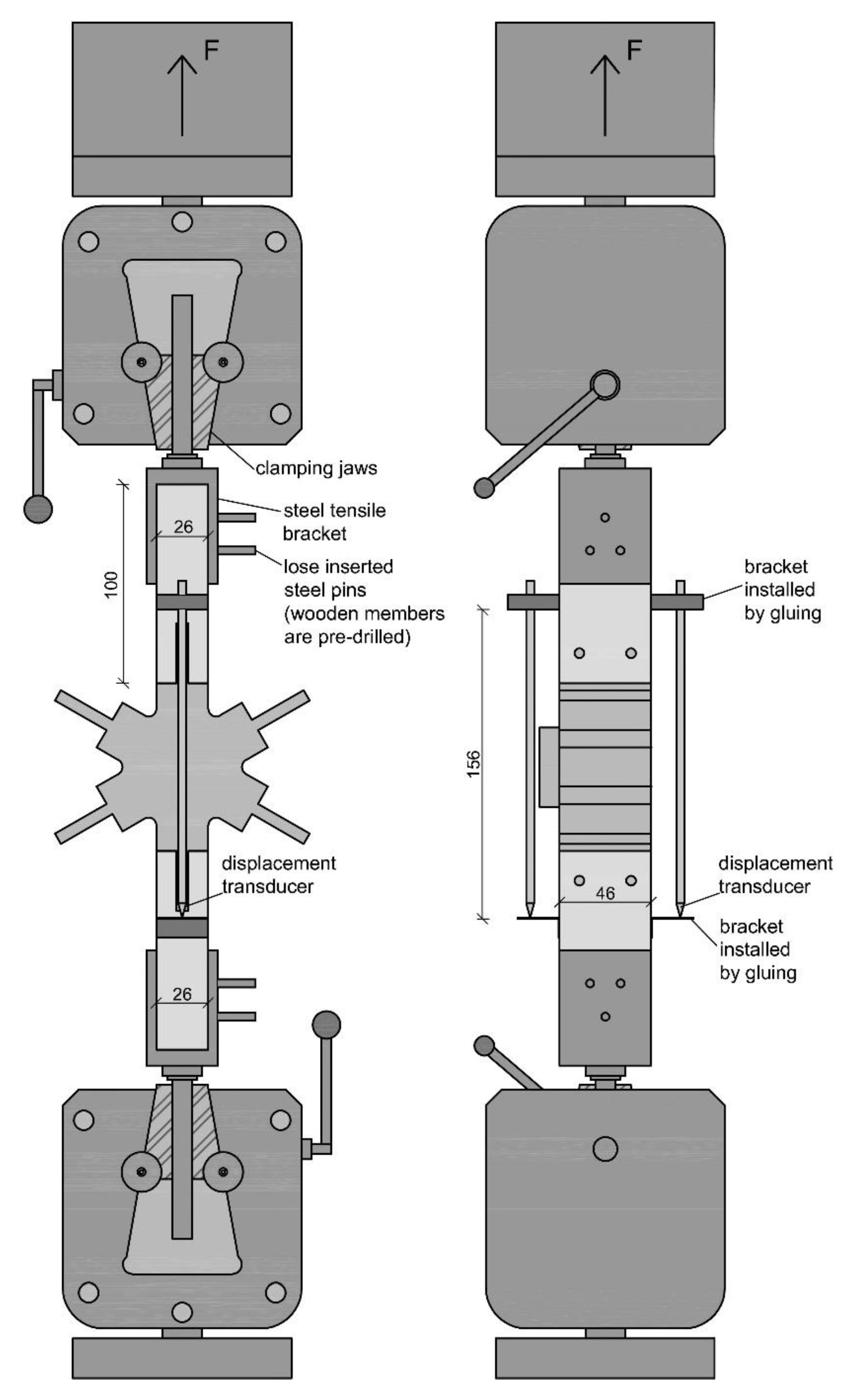
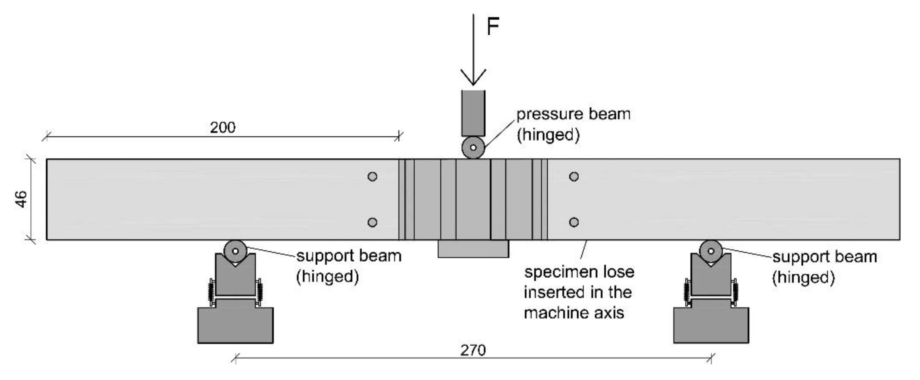
3.2. Test Setups and Test Realization
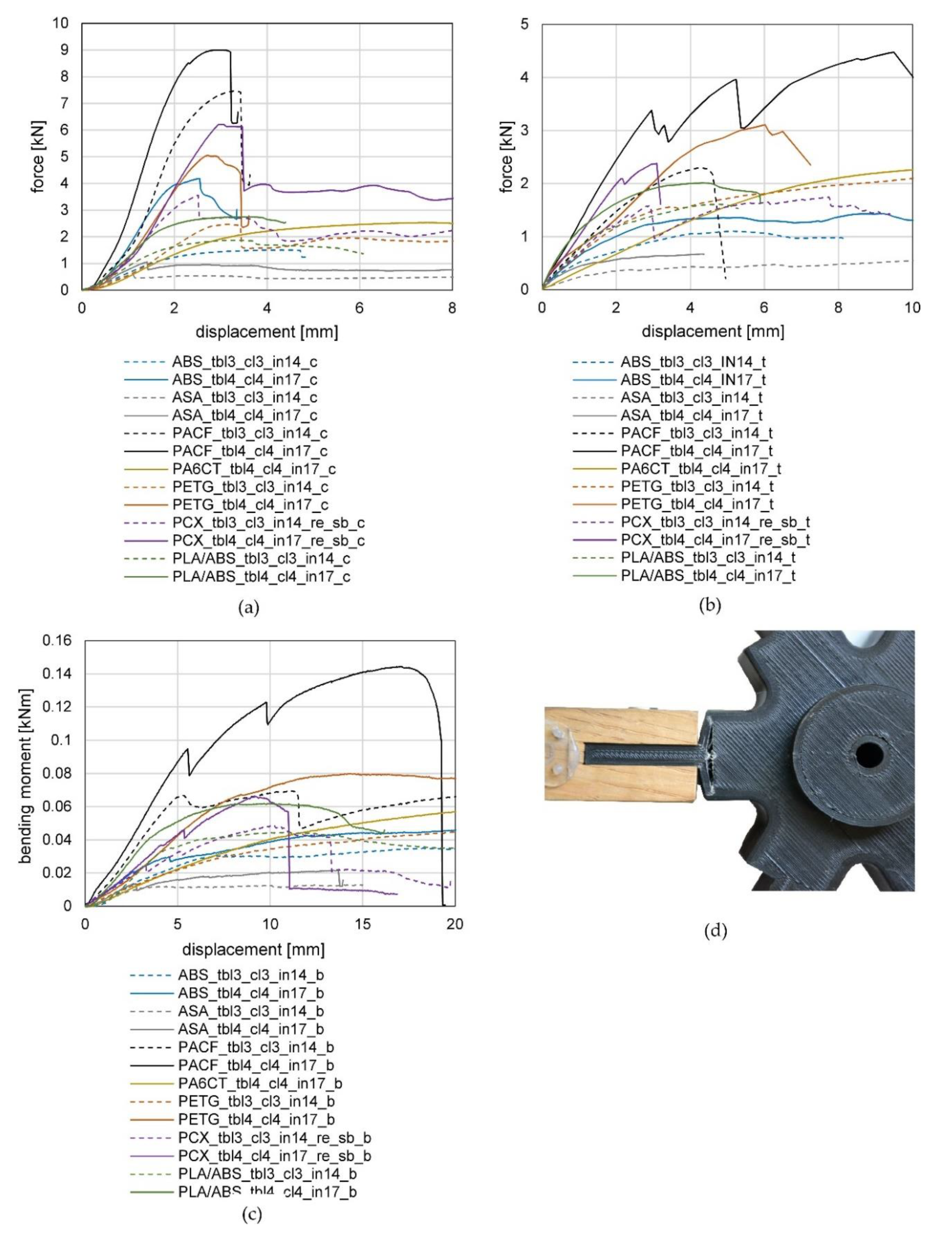
3.3. Results of Test Series 1
3.3.1. Results of the Compression Tests of Series 1
3.3.2. Results of the Tension Tests of Series 1
3.3.3. Results of the Bending Tests of Series 1
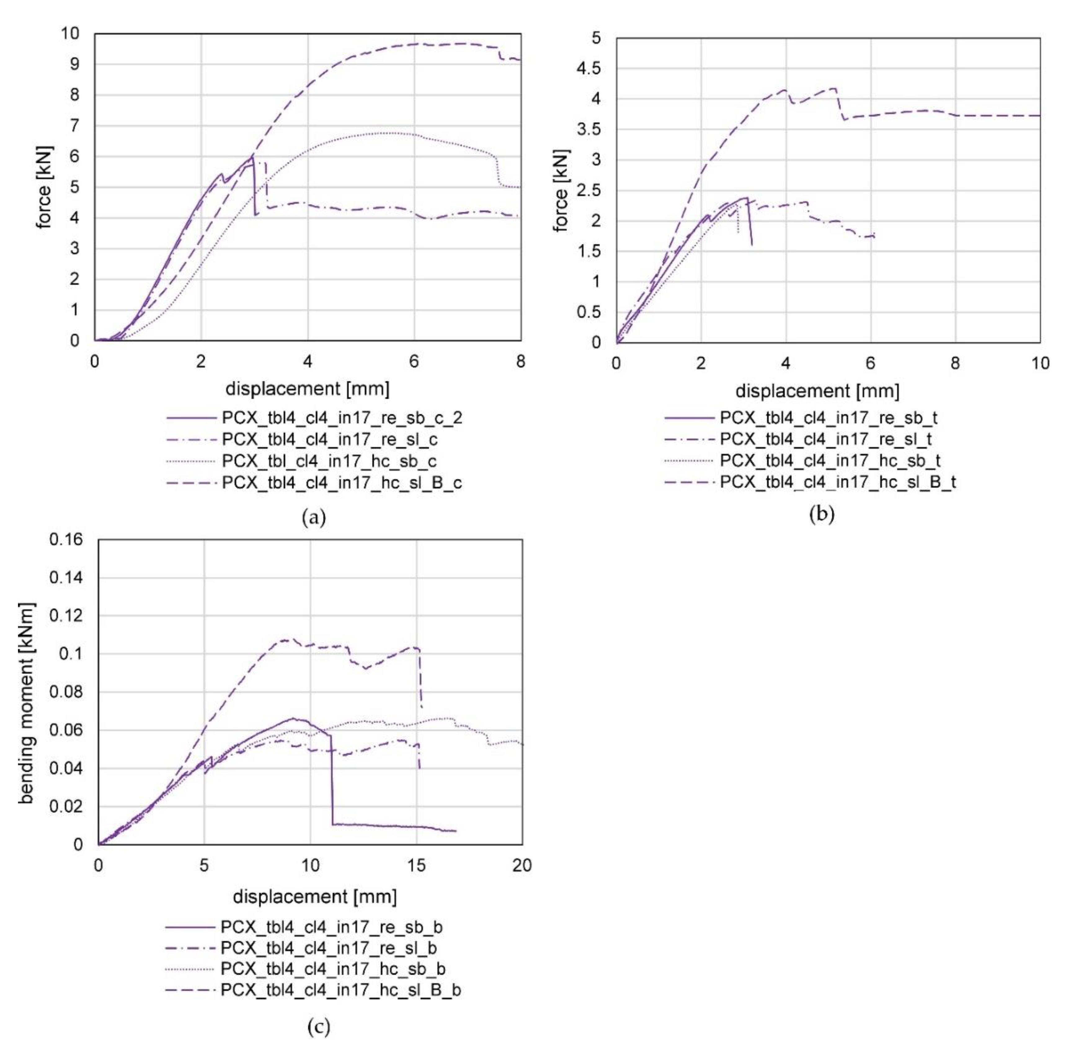
3.4. Results of Test Series 2
3.4.1. Results of the Compression Tests of Series 2
3.4.2. Results of the Tension Tests of Series 2
3.4.3. Results of the Bending Tests of Series 2
3.5. Analysis of the Production of the Test Specimens and the Experiments
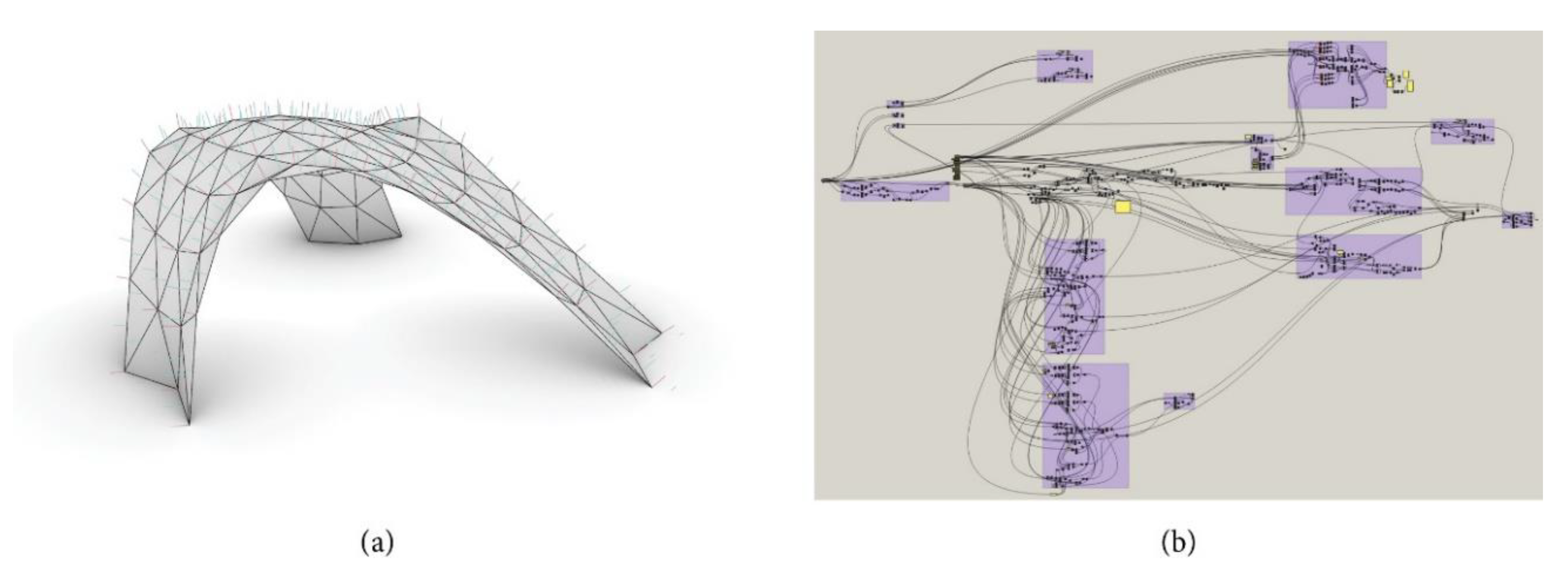
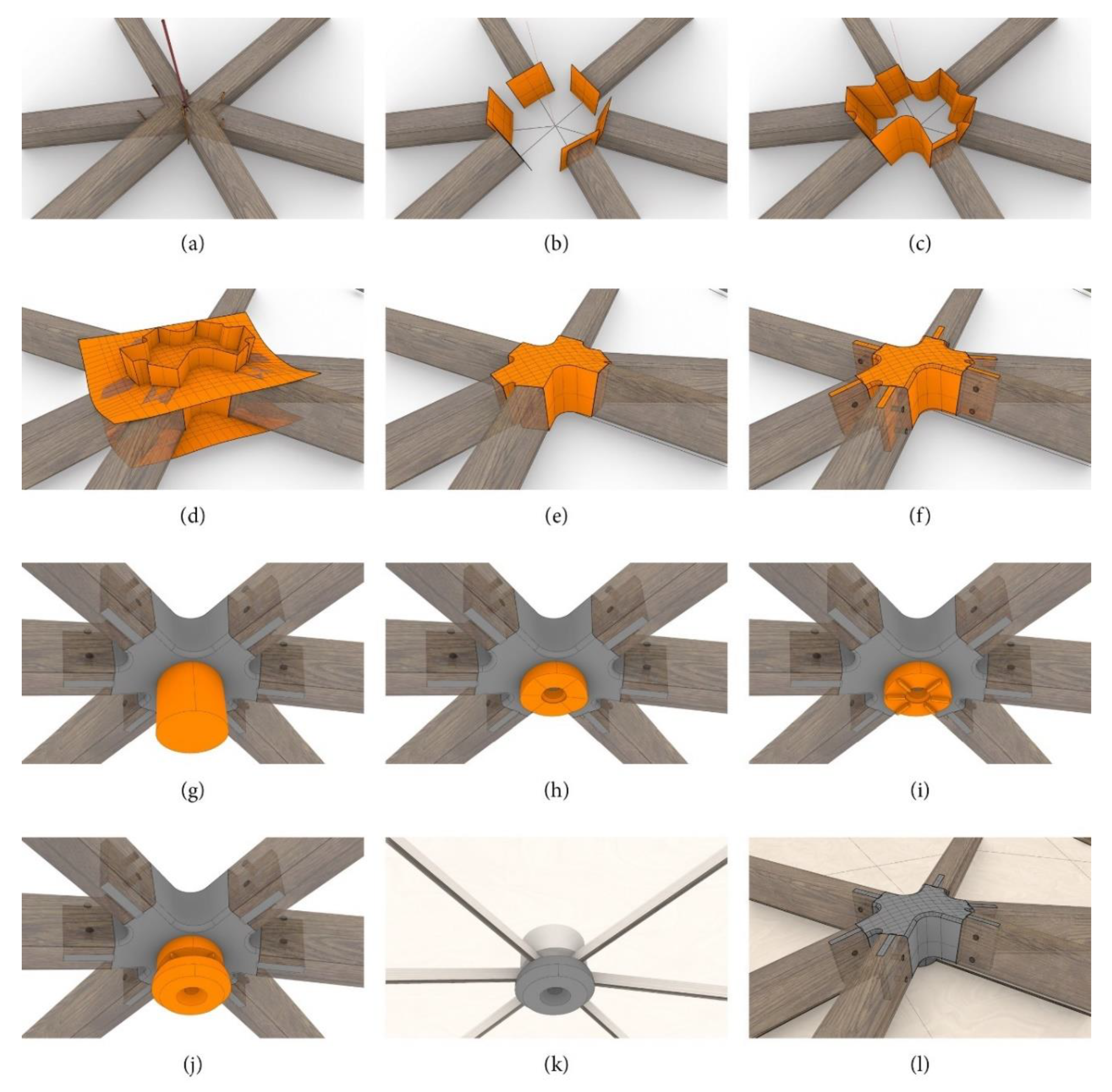
4. Automated Design Approach for the Knots
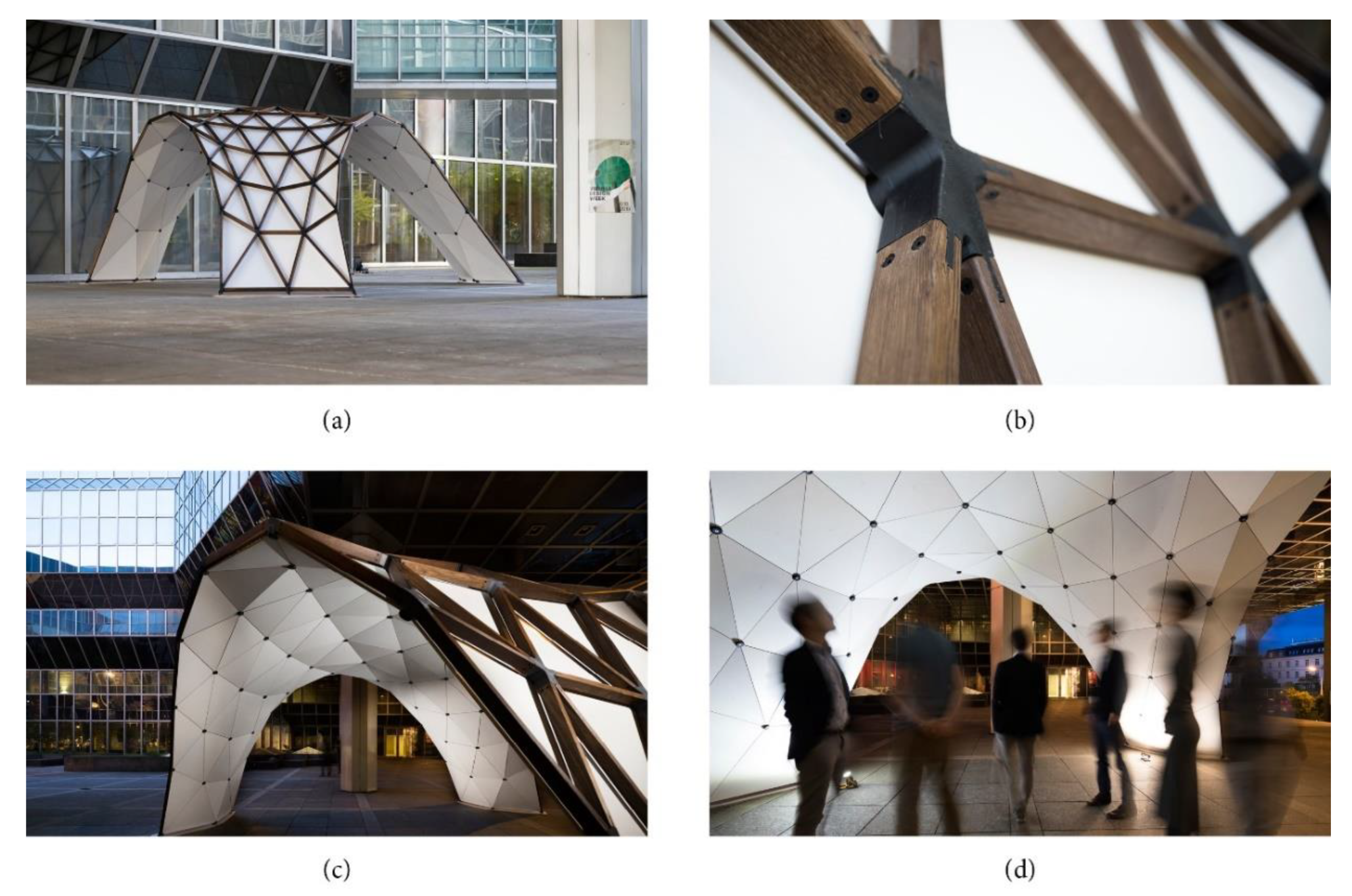
5. Design and Construction of the Full-Scale Prototype
5.1. Design
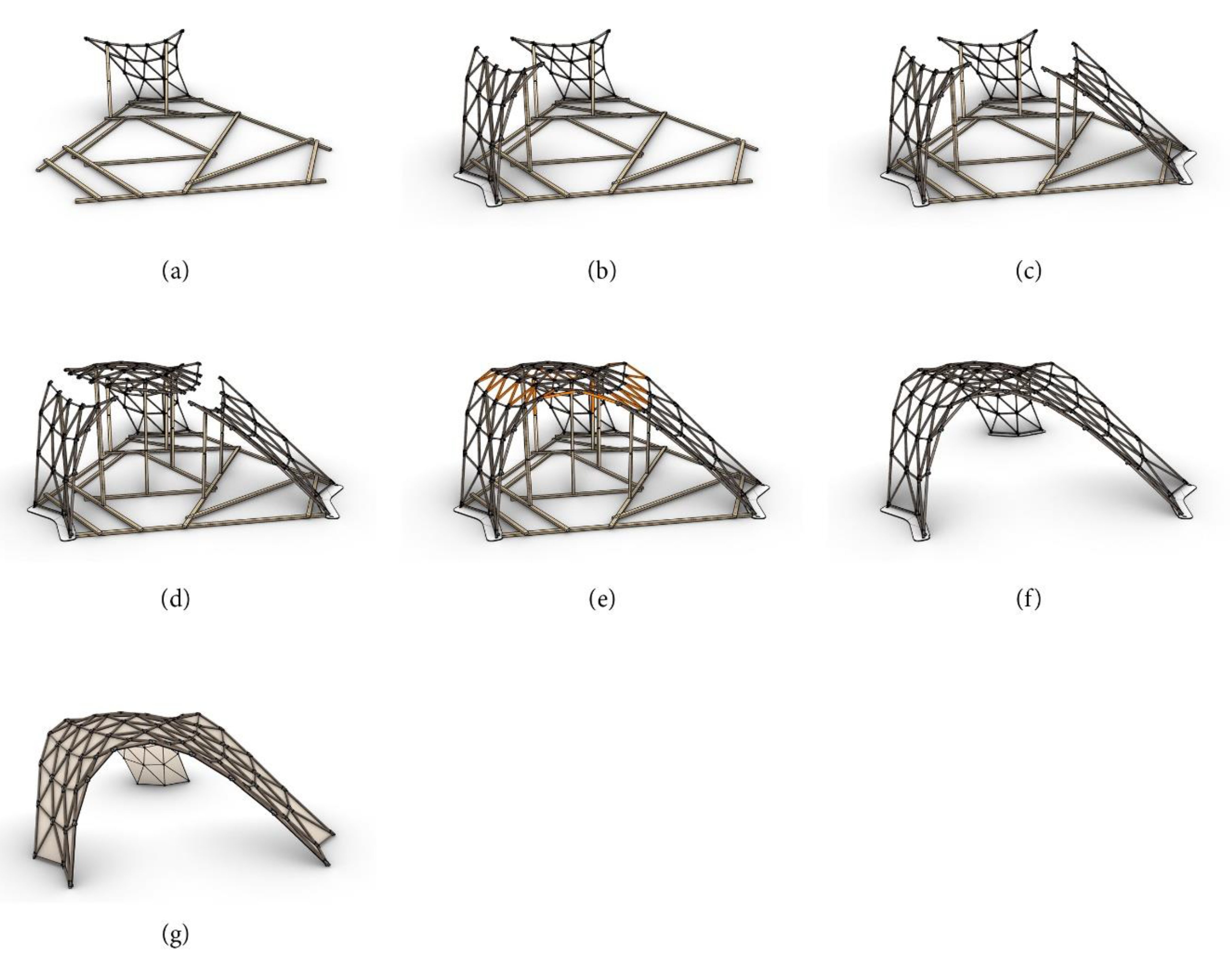
5.2. Assembly
6. Summary
Author Contributions
Funding
Acknowledgments
Conflicts of Interest
Abbreviations
| Tbl | top and bottom layer |
| cl | contour layer |
| in | infill |
| c | compression |
| t | tension |
| b | bending |
| ABS | Acrylonitrile butadiene styrene-based material |
| ASA | Acrylic styrene acrylonitrile-based material |
| PACF | Advanced carbon fiber infused polyamide-based material |
| PA6CT | Polyamide-6/6,6-copolymer-based material |
| PCX | Polycarbonate-based material |
| PETG | Polyethylene terephthalate (PET) modified with glycol |
| PLA | Polylactide |
References
- Brown, S.; Cook, M. The Design and Manufacture of the British Museum Great Court Roof. In Proceedings of the IABSE Symposium 2002: Towards a Better Built Environment—Innovation, Sustainability, Information Technology, Melbourne, Australia, 11–13 September 2002. [Google Scholar]
- Stephan, S.; Sánchez-Alvarez, J.; Knebel, K. Stabwerke auf Freiformflächen. Stahlbau 2004, 73, 562–572. [Google Scholar] [CrossRef]
- Nemeth, Z.; Purer, L.; Schmidt, G.; Schnebel, P.; Sischka, J. Knoten zum Verbinden von Stäben eines Flächentragwerks. Patent EP1593789A2, 9 September 2005. [Google Scholar]
- Rochas, A. Universal Node for Space Frame Structures. U.S. Patent US8820025B1, 2 September 2014. [Google Scholar]
- Galjaard, S.; Hofman, S.; Ren, S. New Opportunities to Optimize Structural Designs in Metal by Using Additive Manufacturing. In Proceedings of the Advances in Architectural Geometry 2014, London, UK, 18–21 September 2014; Block, P., Knippers, J., Mitra, N.J., Wang, W., Eds.; Springer: Cham, Switzerland, 2015; pp. 79–93. [Google Scholar]
- Strauß, H. AM Envelope—The Potential of Additive Manufacturing for Façade Construction. Ph.D. Thesis, TU Delft, Delft, The Netherlands, 2013. [Google Scholar]
- Ford, S.; Despeisse, M. Additive manufacturing and sustainability: An exploratory study of the advantages and challenges. J. Clean. Prod. 2016, 137, 1573–1587. [Google Scholar] [CrossRef]
- Rejeski, D.; Zhao, F.; Huang, Y. Research needs and recommendations on environmental implications of additive manufacturing. Addit. Manuf. 2018, 19, 21–28. [Google Scholar] [CrossRef]
- Austrian Standards ÖNORM EN ISO 527-1: 2019 12 01—Kunststoffe—Bestimmung der Zugeigenschaften—Teil 1: Allgemeine Grundsätze (ISO 527-1:2019). 2019. Available online: https://shop.austrian-standards.at/action/de/public/details/666093/OENORM_EN_ISO_527-1_2019_12_01 (accessed on 21 April 2020).
- Austrian Standards ÖNORM EN ISO 527-3: 2019 02 01—Kunststoffe—Bestimmung der —Teil 3: Prüfbedingungen für Folien und Tafeln (ISO 527-3:2018). 2019. Available online: https://shop.austrian-standards.at/action/de/public/details/649245/OENORM_EN_ISO_527-3_2019_02_01;jsessionid=B273E60000D98792F96EC16383F95234 (accessed on 21 April 2020).
- Austrian Standards ÖNORM EN ISO 527-2: 2012 05 15—Kunststoffe—Bestimmung der Zugeigenschaften—Teil 2: Prüfbedingungen für Form- und Extrusionsmassen (ISO 527-2:2012). 2012. Available online: https://shop.austrian-standards.at/action/de/public/details/427184/OENORM_EN_ISO_527-2_2012_05_15 (accessed on 21 April 2020).
- Austrian Standards ÖNORM EN ISO 527-5: 2009 12 15—Kunststoffe—Bestimmung der Zugeigenschaften—Teil 5: Prüfbedingungen für unidirektional faserverstärkte Kunststoffverbundwerkstoffe (ISO 527-5:2009). 2009. Available online: https://shop.austrian-standards.at/action/de/public/details/351557/OENORM_EN_ISO_527-5_2009_12_15;jsessionid=07AD8E3DD6F52EA000EB5B7999EEED2E (accessed on 21 April 2020).
- Austrian Standards ÖNORM EN ISO 527-4: 1997 09 01—Kunststoffe—Bestimmung der Zugeigenschaften—Teil 4: Prüfbedingungen für isotrop und anisotrop faserverstärkte Kunststoffverbundwerkstoffe (ISO 527-4:1997). 1997. Available online: https://shop.austrian-standards.at/action/de/public/details/56464/OENORM_EN_ISO_527-4_1997_09_01 (accessed on 21 April 2020).
- Dizon, J.R.C.; Espera, A.H.; Chen, Q.; Advincula, R.C. Mechanical characterization of 3D-printed polymers. Addit. Manuf. 2018, 20, 44–67. [Google Scholar] [CrossRef]
- Domingo-Espin, M.; Puigoriol-Forcada, J.M.; Garcia-Granada, A.-A.; Llumà, J.; Borros, S.; Reyes, G. Mechanical property characterization and simulation of fused deposition modeling Polycarbonate parts. Mater. Des. 2015, 83, 670–677. [Google Scholar] [CrossRef]
- Masood, S.H.; Mau, K.; Song, W.Q. Tensile Properties of Processed FDM Polycarbonate Material. Available online: https://www.scientific.net/msf.654-656.2556 (accessed on 26 January 2020).
- Rodríguez, J.F.; Thomas, J.P.; Renaud, J.E. Mechanical behavior of acrylonitrile butadiene styrene (ABS) fused deposition materials. Experimental investigation. Rapid Prototyp. J. 2001, 7, 148–158. [Google Scholar] [CrossRef]
- Justo, J.; Távara, L.; García-Guzmán, L.; París, F. Characterization of 3D printed long fibre reinforced composites. Compos. Struct. 2018, 185, 537–548. [Google Scholar] [CrossRef]
- Smith, W.C.; Dean, R.W. Structural characteristics of fused deposition modeling polycarbonate material. Polym. Test. 2013, 32, 1306–1312. [Google Scholar] [CrossRef]
- Zhou, Y.-G.; Zou, J.-R.; Wu, H.-H.; Xu, B.-P. Balance between Bonding and Deposition During Fused Deposition Modeling of Polycarbonate and Acrylonitrile-Butadiene-Styrene Composites. Available online: https://www.ingentaconnect.com/content/bpl/pc/2020/00000041/00000001/art00003 (accessed on 4 April 2020).
- Martínez, J.; Diéguez, J.L.; Ares, E.; Pereira, A.; Hernández, P.; Pérez, J.A. Comparative between FEM Models for FDM Parts and their Approach to a Real Mechanical Behaviour. Procedia Eng. 2013, 63, 878–884. [Google Scholar] [CrossRef]
- Ćwikła, G.; Grabowik, C.; Kalinowski, K.; Paprocka, I.; Ociepka, P. The influence of printing parameters on selected mechanical properties of FDM/FFF 3D-printed parts. IOP Conf. Ser. Mater. Sci. Eng. 2017, 227, 012033. [Google Scholar] [CrossRef]
- Ahn, S.; Montero, M.; Odell, D.; Roundy, S.; Wright, P.K. Anisotropic material properties of fused deposition modeling ABS. Rapid Prototyp. J. 2002, 8, 248–257. [Google Scholar] [CrossRef]
- Shojib Hossain, M.; Espalin, D.; Ramos, J.; Perez, M.; Wicker, R. Improved Mechanical Properties of Fused Deposition Modeling-Manufactured Parts Through Build Parameter Modifications. J. Manuf. Sci. Eng. 2014, 136. [Google Scholar] [CrossRef]
- García-Domínguez, A.; Claver, J.; Sebastián, M.A. Methodology for the optimization of work pieces for additive manufacturing by 3D printing. Procedia Manuf. 2017, 13, 910–915. [Google Scholar] [CrossRef]
- Xioneer GmbH Xioneer GmbH. Available online: https://www.xioneer.com/ (accessed on 26 January 2020).
- McNeel Europe Grasshopper—Algorithmic Modeling for Rhino. Available online: https://www.grasshopper3d.com/ (accessed on 28 January 2020).
- Kromoser, B.; Pachner, T.; Tang, C.; Kollegger, J.; Pottmann, H. Form-finding of shell bridges using the Pneumatic Forming of Hardened Concrete construction principle. Adv. Civ. Eng. 2018. [Google Scholar] [CrossRef]
- Adriaenssens, S.; Block, P.; Veenendaal, D.; Williams, C. Shell Structures for Architecture: Form Finding and Optimization; Routledge: Abingdon, UK, 2014; ISBN 978-1-317-90938-5. [Google Scholar]
- McNeel Europe Kangaroo—Grasshopper. Available online: https://www.grasshopper3d.com/group/kangaroo (accessed on 28 January 2020).
- McNeel Europe Rhino 6 für Windows. Available online: https://www.rhino3d.com/de/ (accessed on 28 January 2020).
- Bollinger und Grohmann ZT GmbH: Karamba3D—Parametric Engineering. 2020. Available online: https://www.karamba3d.com/ (accessed on 19 April 2020).
- Austrian Standards. ÖNORM EN 1990: 2013 03 15—Eurocode—Grundlagen der Tragwerksplanung; Austrian Standards: Vienna, Austria, 2013. [Google Scholar]
- Austrian Standards. ÖNORM EN 1995-1-1: 2019 06 01—Eurocode 5: Bemessung und Konstruktion von Holzbauten—Teil 1-1: Allgemeines—Allgemeine Regeln und Regeln für den Hochbau; Austrian Standards: Vienna, Austria, 2019. [Google Scholar]


| Specimen Designation | Material | Top/Bottom Layers | Contour Layers | Infill Percentage |
|---|---|---|---|---|
| ABS_tbl3_cl3_in14 | ABS | 3 | 3 | 14 |
| ABS_tbl4_cl4_in17 | ABS | 4 | 4 | 17 |
| ASA_tbl3_cl3_in14 | ASA | 3 | 3 | 14 |
| ASA_tbl4_cl4_in17 | ASA | 4 | 4 | 17 |
| PACF_tbl3_cl3_in14 | PACF | 3 | 3 | 14 |
| PACF_tbl4_cl4_in17 | PACF | 4 | 4 | 17 |
| PA6CT_tbl4_cl4_in17 | PA6CT | 4 | 4 | 17 |
| PETG_tbl3_cl3_in14 | PETG | 3 | 3 | 14 |
| PETG_tbl4_cl4_in17 | PETG | 4 | 4 | 17 |
| PCX_tbl3_cl3_in14 | PCX | 3 | 3 | 14 |
| PCX_tbl4_cl4_in17 | PCX | 4 | 4 | 17 |
| PLA/ABS_tbl3_cl3_in14 | PLA/ABS | 3 | 3 | 14 |
| PLA/ABS_tbl4_cl4_in17 | PLA/ABS | 4 | 4 | 17 |
| Specimen Designation | Material | Top/Bottom Layers | Contour Layers | Infill [%] | Infill Type | Screw Type |
|---|---|---|---|---|---|---|
| PCX_tbl4_cl4_in17_re_sb | PCX | 4 | 4 | 17 | rectangular | sleeve bolts |
| PCX_tbl4_cl4_in17_re_sl | PCX | 4 | 4 | 17 | rectangular | sleeve w. screws |
| PCX_tbl4_cl4_in17_hc_sb | PCX | 4 | 4 | 17 | honeycomb | sleeve bolts |
| PCX_tbl4_cl4_in17_hc_sl_B | PCX | 4 | 4 | 17 | honeycomb | sleeve w. screws |
| Material | Layer Height [mm] | Layer Widths [mm] | Nozzle Diameter [mm] | Chamber Temperature [°C] | Extrusion Temperature [°C] | Bed Temperature [°C] | Standard Printing Speed [mm/min] |
|---|---|---|---|---|---|---|---|
| ABS_s | 0.2 | 0.504 | 0.4 | 60 | 245 | 90 | 3000 |
| ASA_s | 0.2 | 0.528 | 0.4 | 60 | 265 | 90 | 3300 |
| PACF_s | 0.2 | 0.792 | 0.6 | 70 | 270 | 100 | 2400 |
| PA6CT_s | 0.2 | 0.528 | 0.4 | 50 | 260 | 60 | 3000 |
| PETG_s | 0.2 | 0.552 | 0.4 | 40 | 255 | 60 | 3600 |
| PCX_s | 0.2 | 0.504 | 0.4 | 70 | 260 | 105 | 3600 |
| PCX_b | 0.5 | 1.056 | 0.8 | 70 | 260 | 105 | 2100 |
| Material | UV Resist. | Water Resist. | Chemical Resist. | Tensile Strength at Yield (ISO 527) [MPa] | Tensile Modulus (ISO 527) (MPa) | Density (ISO 1183) [g/cm3] | Strain at Break [%] | Heat Deflection Temp. [°C] |
|---|---|---|---|---|---|---|---|---|
| ABS | no | - | no | 35.0 | 2030 | 1.03 | 8 | 103 |
| ASA | yes | yes | - | 47.5 | 2020 | 1.11 | 15 | 98 |
| PACF | - | - | - | 107.0 | - | 1.40 | 2 | 120 |
| PA6CT | - | - | - | 66.2 | 2223 | 1.12 | 10 | 67 |
| PETG | - | - | - | 50.0 | 2020 | 1.27 | 23 | 70 |
| PCX | yes | - | - | 59.7 | 2048 | 1.19 | 12.2 | 113 |
| PLA/ABS | no | - | no | 40.0 | 4000 | 1.27 | 47 | 95 |
© 2020 by the authors. Licensee MDPI, Basel, Switzerland. This article is an open access article distributed under the terms and conditions of the Creative Commons Attribution (CC BY) license (http://creativecommons.org/licenses/by/4.0/).
Share and Cite
Kromoser, B.; Pachner, T. Optiknot 3D—Free-Formed Frameworks out of Wood with Mass Customized Knots Produced by FFF Additive Manufactured Polymers: Experimental Investigations, Design Approach and Construction of a Prototype. Polymers 2020, 12, 965. https://doi.org/10.3390/polym12040965
Kromoser B, Pachner T. Optiknot 3D—Free-Formed Frameworks out of Wood with Mass Customized Knots Produced by FFF Additive Manufactured Polymers: Experimental Investigations, Design Approach and Construction of a Prototype. Polymers. 2020; 12(4):965. https://doi.org/10.3390/polym12040965
Chicago/Turabian StyleKromoser, Benjamin, and Thomas Pachner. 2020. "Optiknot 3D—Free-Formed Frameworks out of Wood with Mass Customized Knots Produced by FFF Additive Manufactured Polymers: Experimental Investigations, Design Approach and Construction of a Prototype" Polymers 12, no. 4: 965. https://doi.org/10.3390/polym12040965
APA StyleKromoser, B., & Pachner, T. (2020). Optiknot 3D—Free-Formed Frameworks out of Wood with Mass Customized Knots Produced by FFF Additive Manufactured Polymers: Experimental Investigations, Design Approach and Construction of a Prototype. Polymers, 12(4), 965. https://doi.org/10.3390/polym12040965