Article

5-Channel Polymer/Silica Hybrid Arrayed Waveguide Grating

1
Wuhan National Laboratory for Optoelectronics and School of Optical and Electronic Information, Huazhong University of Science and Technology, Wuhan 430074, China
2
State Key Laboratory of Integrated Optoelectronics, College of Electronic Science and Engineering, Jilin University, Changchun 130012, China
*
Authors to whom correspondence should be addressed.
These authors contribute equally to this work.
Polymers 2020, 12(3), 629; https://doi.org/10.3390/polym12030629
Submission received: 13 February 2020 / Revised: 4 March 2020 / Accepted: 7 March 2020 / Published: 10 March 2020
(This article belongs to the Section Polymer Physics and Theory)

Abstract

:
A 5-channel polymer/silica hybrid arrayed waveguide grating (AWG), fabricated through a simple and low-cost microfabrication process is proposed, which covers the entire O-band (1260–1360 nm) of the optical communication wavelength system. According to the simulation results, the insertion loss is lower than 4.7 dB and the crosstalk within 3-dB bandwidth is lower than ~−28 dB. The actual fiber–fiber insertion loss is lower than 14.0 dB, and the crosstalk of the 5 channels is less than −13.0 dB. The demonstrated AWG is ideally suitable for optical communications, but also has potential in the multi-channel sensors.

Graphical Abstract

1. Introduction

With the rapid growth of data center interconnection, a coarse wavelength division multiplexing (CWDM) system in the O-band (1260–1360 nm) becomes the first choice for metro-access networks, owing to its low cost in equipment, operation, and maintenance [1,2]. To realize wavelength division, many kinds of structures have been proposed, including arrayed waveguide grating (AWG), planar concave grating (PCG) [3], and microring resonator (MRR) [4]. Specifically, AWG has advantages of low cost, large fabrication tolerance, and high performance, and has been widely studied. As the centerpiece of wavelength division multiplexing (WDM), AWG has been fabricated by silicon-on-insulator [5], SiO2 [6,7], and polymers [8,9,10,11]. Though AWG has been highly developed by the standard industry technology of planar lightwave circuits (PLCs), and the cost is being gradually reduced by the mature fabrication process of silica-based waveguide [12,13,14], the polymer AWG has its own advantages and can avoid complex preparation processes such as thermal oxidation, plasma-enhanced chemical vapor deposition (PECVD), and inductively coupled plasma (ICP) etching [12,13,14]. Compared with silica-based devices, polymer-based devices can skip several steps in manufacture, resulting in reduced prices for the setup and, especially for small batch sizes, a reduced price per unit [15,16,17]. Moreover, due to good compatibility on diverse substrates, polymer-based devices can provide suitable platforms for the hybrid integration of photonic chips [18,19,20]. Besides having the advantages of low cost, small birefringence, easy control of refractive index, large thermo-optic coefficients, and easy fabrication, compared with inorganic materials, biocompatibility is an especially important and unique feature of polymers, which makes them an ideal material platform for photonic integrated waveguide biosensors [18]. We built up a multi-channel sensor system based on separate devices, including a dense wavelength division multiplexing (DWDM) and sensors [21]. Furthermore, CWDM can supply larger bandwidth compared with DWDM, which is much more suitable to build up a multi-channel sensor system and fabricate monolithic multi-channel sensors [22]. There is plenty of research about CWDM [23,24], however, less of it is based on polymer materials [25,26], to the best of our knowledge. Still, it remains challenging to reduce the insertion loss and the crosstalk of the polymeric AWG.
In this paper, we designed and fabricated a 5-channel AWG based on polymer/silica hybrid waveguide, covering the entire O-band of the optical communication wavelength system. According to the simulation results, the insertion loss is lower than 4.7 dB in the O-band, and the crosstalk within 3-dB bandwidth is lower than ~−28 dB. Also, the AWG was successfully fabricated through a microfabrication process. Over the O-band, the measured fiber–fiber insertion loss is lower than 14.0 dB. Within 3-dB bandwidth, the crosstalk of each channel is lower than –13.0 dB. The proposed AWG is well-suited for large-scale manufacture, and it has various potential applications, like hybrid integration optical circuits and the monolithic multi-channel sensors. In the future, a packaging method will be developed to improve the performance of the AWG.

2. Device Design and Simulation

In our design, we chose SU-8 2002 photoresist as core material, polymethy-methacrylate (PMMA) as cladding, and silica as substrate, whose refractive indexes are 1.571, 1.483, and 1.446, respectively, measured with an M-2000UI variable angle incidence spectroscopic ellipsometer at 1550 nm wavelength (J.A.Woollam Co., Inc., Lincoln, NE, USA). SU-8 2002 photoresist is a commercially available negative UV photoresist, which has very high transmission for wavelengths above 400 nm [27] and exhibits relatively good chemical and thermal stability (with a glass transition temperature of Tg ≈ 200 ℃ and a degradation temperature of Td ≈ 380 ℃) [28]. Here, we chose silica as the substrate for the following results. Firstly, polymer and silica materials are immiscible. Secondly, the mechanical strength of silica is much greater than polymer materials, which will improve the yield and reliability of the ICP etching, providing a possibility for hybrid integration for polymer and silica. Thirdly, the coefficient of linear thermal expansion of silica is much smaller than that of the polymer and silicon. They are 0.5 × 10⁻⁶, 0.55 × 10⁻⁴, and 2.5 × 10⁻⁶ K−1, respectively [20].
The design of the waveguide dimensions and AWG geometry was performed with commercial software WDM Phasar (Optiwave Corporation, Ottawa, ON, Canada) under consideration of the refractive indices of the applied materials. The waveguide dimensions were chosen to be as small as possible, while still being reliably producible with conventional contact lithography. Ultimately, this led to a few-mode behavior of the produced AWG due to size limitations, and certain mode dispersion. Nevertheless, we applied mode-division multiplexing in the end of output waveguides to decrease the loss caused by mode dispersion. What is more, it will increase the channel number. The length differences of adjacent arrayed waveguides, focal length of slabs, and FSR are given by [29].
Δ L = m λ 0 n c
f = n s d 2 m Δ λ n c n g
F S R = λ 0 m n c n g
where λ0 is the wavelength in free space, d is the pitch of adjacent waveguides, nc and ns are effective refractive indexes of the rectangular waveguide and slab waveguide, respectively, and ng is the group refractive index. The diffraction order m is an important parameter. Once the diffraction order was determined, some geometries of the device were also determined. Figure 1a shows the relations between the diffraction order m and the length difference ΔL, focal length f, and FSR. Figure 1b shows the relation between the diffraction order m and the maximum number of I/O channels Nmax and the minimum number of arrayed waveguides 2Mmin + 1. In this paper, the number of I/O channels was determined to be 2N + 1 = 5, therefore, the diffraction order should be taken as m = 11. The minimum number of array waveguides was 2Mmin + 1 = 19. In fact, the number of arrayed waveguides should be taken as large as possible in order to decrease the loss. However, it is also constrained by the device size. Finally, we chose 2M + 1 = 25. In summary, the optimized parameter values of the AWG multiplexer are listed in Table 1.
As shown in Figure 2, the entire footprint of the AWG layout was 13000 × 2463 μm2, and the footprint of the array waveguide region was 3065 × 825 μm2. At the ends of input and output waveguides, we used taper waveguide structure to reduce the coupler loss. The width of taper waveguides changed from 3 to 7 μm linearly. The length of taper structure was 75 μm. Also we used taper waveguides between slab waveguides region and array waveguides region. Limited by the number of array waveguides, the width of waveguides changed from 4 to 3 μm linearly. The lengths of taper waveguides were set at 70 μm.
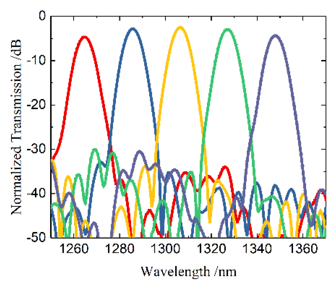
The simulated transmission spectrum is illustrated in Figure 3. As shown in Figure 2, the central wavelengths of each channel were 1264.5, 1285.6, 1306.7 nm, 1327.2, and 1347.7 nm, respectively. The insertion loss was lower than 4.7 dB in the O-band. 3-dB bandwidth of each channel was 8 nm. The crosstalk within 3-dB bandwidth was lower than ~−28 dB.

3. Device Fabrication and Characterization

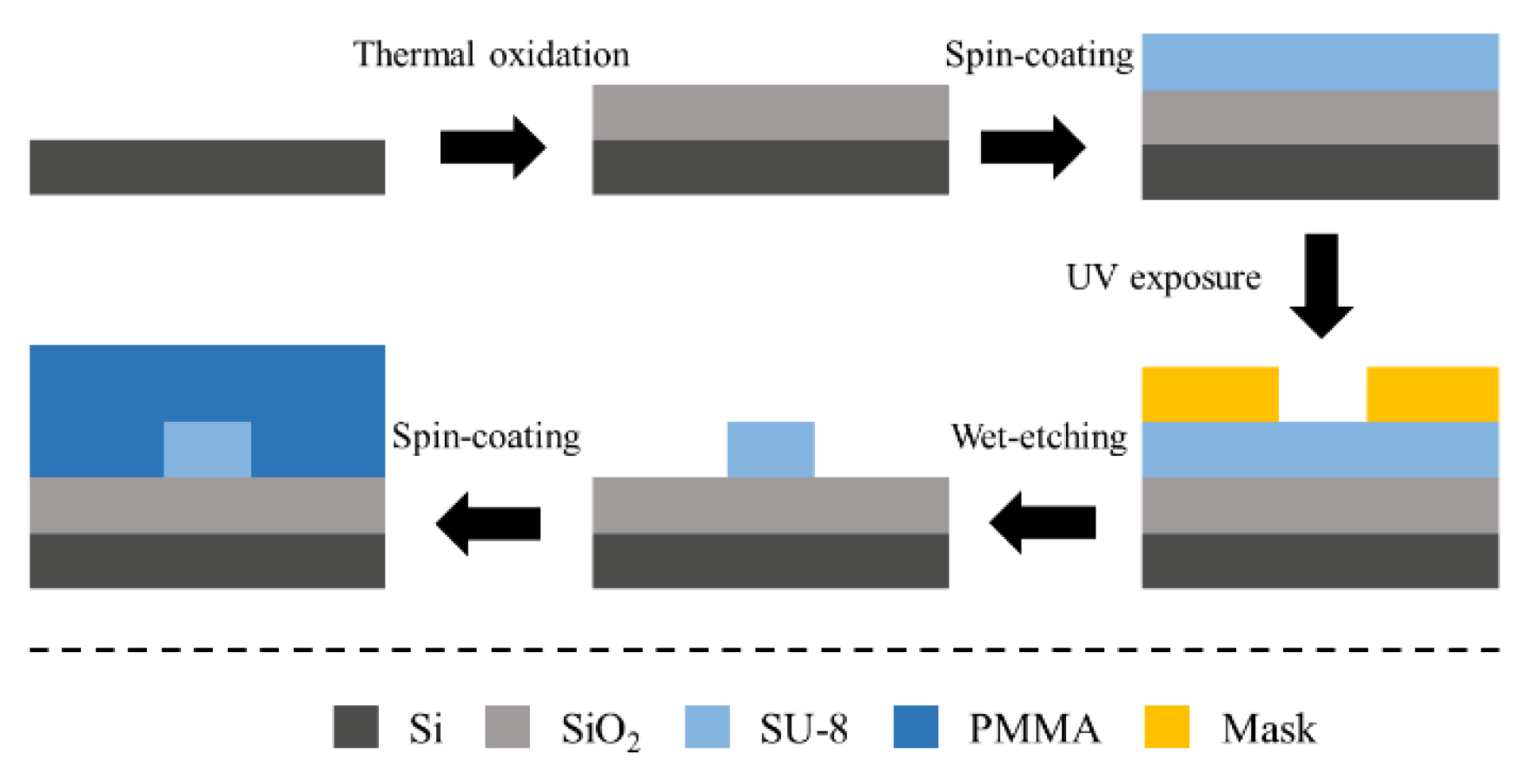
The fabrication process flow of the AWG is shown in Figure 4. Negative photoresist SU-8 2002 was spin-coated as the core layer onto the silica substrate layer at a rotational speed of 1500 r/min and prebaked at 95 ℃ for 10 min. Then the coated chip was exposed to UV light from a mercury discharge lamp (peak emission wavelength, 365 nm; irradiance, 23 mW/cm2, ABM-USA, Inc., San Jose, CA, USA) for 3 s and post-baked at 95 ℃ for 10 min. After that, we removed the unexposed SU-8 polymer and then hard-baked it at 125 ℃. Finally, 5-μm-thick PMMA upper cladding was spin-coated on the waveguide cores and baked at 125 ℃ for 2.5 h. The micrographs of the fabricated AWG are shown in Figure 5. Figure 5a shows the cross-section of the fabricated AWG. Figure 5b shows the overall structure diagram of the AWG. Figure 5c,d is the enlarged diagrams of the connection parts between the planar waveguide region and array waveguide region, and the connection parts between the planar waveguide region and output waveguide region, respectively. Here, the minimum distance between array waveguides was 2 μm.
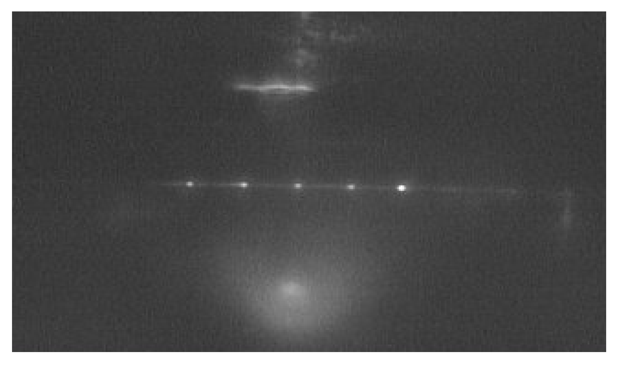
The device under test (DUT) consisted of a broad-spectrum laser (SC-5, Yangtze Soton Laser, Wuhan, China) and an optical spectrum analyzer (MS9740A, Anritsu, Kanagawa, Japan). The near-field pattern of the AWG device is shown in Figure 6. The light from the broad-spectrum laser was coupled into the AWG by a lensed fiber. We monitored the transmission spectrum of each channel of the AWG with the optical spectrum analyzer. The measured transmission spectrum of the AWG is shown in Figure 6, which was basically consistent with the simulation results. From Figure 7, the peak wavelengths of each channel were 1265.5, 1282.2, 1305.3, 1323.4, 1345.6 nm, respectively. The averaged channel spacing was ~20 nm. Compared with the simulation spectrum, the peak wavelength shifting were +1, −3.4, +1.4, +3.8, and +2.1 nm, respectively.
The insertion loss of the straight reference waveguide was measured to be ~11.9 dB. The sample had a total length of 1.3 cm. The propagation loss in the reference waveguide, measured by the cutback method, was ~1.4 dB/cm. Therefore, the edge coupling loss between the waveguide and fiber was ~5 dB/facet [15]. Based on the above analysis, we can conclude that the insertion loss of the device is mainly caused by the edge coupling loss. It can be further improved by polishing the facets of the device or introducing grating coupler. The 3-dB bandwidths of each channel were 5.7, 5.3, 7.2, 10.9, and 7.0 nm, respectively. Within 3-dB bandwidth, the crosstalk of each channel was lower than −13.0 dB.

4. Conclusions

In summary, a 5-channel polymer/silica hybrid AWG was designed and experimentally demonstrated. The introduction of a silica bottom layer decreased the loss and crosstalk. Besides, this fabricated process was compatible with PLC flow. The hybrid integrated devices will further improve device performance. According to the simulation results, the central wavelengths of each channel were 1264.5, 1285.6, 1306.7, 1327.2, and 1347.7 nm, respectively. The insertion loss was lower than 4.7 dB in the O-band. The crosstalk within 3-dB bandwidth was lower than ~-28 dB. Also, the AWG was fabricated successfully through a microfabrication process. The central wavelengths of each channel were 1265.5, 1282.2, 1305.3, 1323.4, and 1345.6 nm, respectively. Over the O-band, the insertion loss was lower than 14.0 dB, which mainly comes from the coupling loss between the input/output waveguide and the fibers. Within 3-dB bandwidth, the crosstalk of each channel was lower than -13.0 dB. The AWG is very well-suited for large-scale manufacturing and has broad potential applications, especially for multi-channel sensors. In the future work, the packaging method will be developed to improve the performance of the AWG.

Author Contributions

Methodology, D.-S.G.; software, S.-R.Z.; validation, Y.-X.Y.; formal analysis, Y.-X.Y. and Z.-Y.L.; data curation, X.-B.W.; writing-original draft preparation, S.-R.Z.; writing-review and editing, Y.-X.Y.; supervision, D.-S.G.; project administration, X.-B.W. All authors have read and agreed to the published version of the manuscript.

Funding

This research was funded by the National Natural Science Foundation of China (Nos. 61875069 and 61975062), the Innovation Fund of WNLO, the Open Fund of the State Key Laboratory of Integrated Optoelectronics (IOSKL2019KF09) and the Fundamental Research Funds for the Central Universities (2019JCXK-59).

Conflicts of Interest

The authors declare no conflict of interest.

References

  1. Banerjee, A.; Park, Y.; Clarke, F.; Song, H.; Yang, S.; Kramer, G.; Kim, K.; Mukherjee, B. Wavelength-division-multiplexed passive optical network (WDM-PON) technologies for broadband access: a review [Invited]. J. Opt. Netw. 2005, 4, 737–758. [Google Scholar] [CrossRef]
  2. Chang, F. Datacenter Connectivity Technologies: Principles and Practice; River Publisher: Gistrup, Denmark, 2018; pp. 4–26, 87–90. [Google Scholar]
  3. Jiang, G.; Baig, S.; Lu, H.; Shen, K.; Wang, M.R. Planar concave grating wavelength demultiplexers with flattened spectral response based on SU-8 polymer waveguides. Opt. Eng. 2016, 55, 037104. [Google Scholar] [CrossRef]
  4. Dai, D. Silicon Nanophotonic Integrated Devices for On-Chip Multiplexing and Switching. J. Lightwave Technol. 2017, 35, 572–587. [Google Scholar] [CrossRef]
  5. Dumon, P.; Bogaerts, W.; Thourhout, D.V.; Taillaert, D.; Baets, R.; Wouters, J.; Beckx, S.; Jaenen, P. Compact wavelength router based on a Silicon-on-insulator arrayed waveguide grating pigtailed to a fiber array. Opt. Express 2006, 14, 664–669. [Google Scholar] [CrossRef] [PubMed]
  6. Li, C.Y.; An, J.M.; Zhang, J.Z.; Wang, L.L.; Li, J.G.; Wang, Y.; Yin, X.J.; Wang, H.J.; Wu, Y.D. 4×20 GHz silica-based AWG hybrid integrated receiver optical sub-assemblies. Chin. Opt. Lett. 2018, 16, 060603. [Google Scholar]
  7. Nishi, H.; Tsuchizawa, T.; Kou, R.; Shinojima, H.; Yamada, T.; Kimura, H.; Ishikawa, Y.; Wada, K.; Yamada, K. Monolithic integration of a silica AWG and Ge photodiodes on Si photonic platform for one-chip WDM receiver. Opt. Express 2012, 20, 9312–9321. [Google Scholar] [CrossRef] [PubMed]
  8. Chen, C.M.; Wang, H.; Wang, L.; Sun, X.Q.; Wang, F.; Zhang, D.M. Athermal polarization-independent 49-channel UV curable all-polymer arrayed waveguide grating (AWG) multiplexer. Optik 2014, 125, 521–525. [Google Scholar] [CrossRef]
  9. Orghici, R.; Bethmann, K.; Zywietz, U.; Reinhardt, C.; Schade, W. All-polymer arrayed waveguide grating at 850 nm: design, fabrication, and characterization. Opt. Lett. 2016, 41, 3940–3943. [Google Scholar] [CrossRef]
  10. Ahn, J.T.; Park, S.; Do, J.Y.; Lee, J.M.; Lee, M.H.; Kim, K.H. Polymer Wavelength Channel Selector Composed of Electrooptic Polymer Switch Array and Two Polymer Arrayed Waveguide Gratings. IEEE Photonics Technol. Lett. 2004, 16, 1567–1569. [Google Scholar] [CrossRef]
  11. Lin, Y.; Rahmanian, N.; Kim, S.; Nordin, G.P.; Topping, C.; Smith, D.W.; Ballato, J. Ultracompact AWG Using Air-Trench Bends With Perfluorocyclobutyl Polymer Waveguides. J. Lightwave Technol. 2008, 26, 3062–3070. [Google Scholar] [CrossRef] [Green Version]
  12. Li, C.Y.; An, J.M.; Wang, J.Q.; Wang, L.L.; Zhang, J.S.; Li, J.G.; Wu, Y.D.; Wang, Y.; Yin, X.J.; Li, Y.; et al. The 8×10 GHz Receiver Optical Subassembly Based on Silica Hybrid Integration Technology for Data Center Interconnection. Chin. Opt. Lett. 2017, 34, 104202. [Google Scholar] [CrossRef]
  13. Ren, M.Z.; Zhang, J.S.; An, J.M.; Wang, Y.; Wang, L.L.; Li, J.G.; Wu, Y.D.; Yin, X.J.; Hu, X.W. Low power consumption 4-channel variable optical attenuator array based on planar lightwave circuit technique. Chin. Phys. B 2017, 26, 074221. [Google Scholar] [CrossRef]
  14. Wang, L.L.; An, J.M.; Zhang, J.S.; Wu, Y.D.; Li, J.G.; Yin, X.J.; Wang, H.J.; Wang, Y.; Zhong, F.; Zha, Q.; et al. Design and fabrication of a low-loss and asymmetric 1 x 5 arbitrary optical power splitter. Appl. Opt. 2016, 55, 8601–8605. [Google Scholar] [CrossRef] [PubMed]
  15. Maria, N.; Dan, A.Z.; Anja, B.; Jörg, H. Single-Mode Waveguide With SU-8 Polymer Core and Cladding for MOEMS Applications. J. Lightwave Technol. 2007, 25, 1284–1289. [Google Scholar]
  16. Yu, X.; Gregory, P.; Zhang, Y.M.; Paddy, F. Single-Mode Tapered Vertical SU-8 Waveguide Fabricated by E-Beam Lithography for Analyte Sensing. Sensors 2019, 19, 3383. [Google Scholar]
  17. Wang, X.B.; Sun, J.; Chen, C.M.; Sun, X.Q.; Wang, F.; Zhang, D.M. Thermal UV treatment on SU-8 polymer for integrated optics. Opt. Mater. Express 2014, 4, 509. [Google Scholar] [CrossRef]
  18. Han, X.Y.; Wu, Z.L.; Yang, S.C.; Shen, F.F.; Liang, Y.X.; Wang, L.H.; Wang, J.Y.; Ren, J.; Jia, L.Y.; Zhang, H.; et al. Recent Progress of Imprinted Polymer Photonic Waveguide Devices and Applications. Polymers 2018, 10, 603. [Google Scholar] [CrossRef] [Green Version]
  19. Tian, L.; Wang, F.; Wu, Y.D.; Sun, X.Q.; Yi, Y.J.; Zhang, D.M. Polymer/silica hybrid integration waveguide Bragg grating based on surface plasmon polaritons. Appl. Opt. 2018, 57, 3607–3611. [Google Scholar] [CrossRef]
  20. Tian, L.; Wang, F.; Wu, Y.D.; Yi, Y.J.; Sun, X.Q.; Zhang, D.M. Polymer/silica hybrid integration add-drop filter based on grating-assisted contradirectional coupler. Opt. Lett. 2018, 43, 2348–2351. [Google Scholar] [CrossRef]
  21. Yin, Y.X.; Wu, Z.F.; Sun, S.W.; Tian, L.; Wang, X.B.; Wu, Y.D.; Zhang, D.M. Multi-functional optical fiber sensor system based on a dense wavelength division multiplexer. Chin. Phys. B 2019, 28, 074202. [Google Scholar] [CrossRef]
  22. Kim, B.K.; Joo, K.N. A multi-channel fiber optic proximity sensor. Meas. Sci. Technol. 2016, 27, 035104. [Google Scholar] [CrossRef]
  23. Kao, H.Y.; Su, Z.X.; Shih, H.S.; Chi, Y.C.; Tsai, C.T.; Kuo, H.C.; Wu, C.H.; Jou, J.J.; Shih, T.T.; Lin, G.R. CWDM DFBLD Transmitter Module for 10-km Interdata Center With Single-Channel 50-Gbit/s PAM-4 and 62-Gbit/s QAM-OFDM. J. Lightwave Technol. 2018, 36, 703–711. [Google Scholar] [CrossRef]
  24. Guerber, S.; Alonso-Ramos, C.; Perez-Galacho, D.; Roux, X.L.; Vulliet, N.; Cremer, S.; Marris-Morini, D.; Boeuf, F.; Vivien, L.; Baudot, C. Design and integration of an O-band silicon nitride AWG for CWDM applications. In Proceedings of the IEEE 14th International Conference on Group IV Photonics, Berlin, Germany, 23–25 August 2017; pp. 133–134. [Google Scholar]
  25. Lu, S.; Yang, C.; Yan, Y.; Jin, G.; Zhou, Z.; Wong, W.H.; Pun, E.Y.B. Design and fabrication of a polymeric flat focal field arrayed waveguide grating. Opt. Express 2005, 13, 9982. [Google Scholar] [CrossRef] [PubMed]
  26. Jack, S.K.; Daniel, P.P.; Pavel, N.; Levent, Y.; Yu, C. Design and fabrication of Poly(dimethylsiloxane) arrayed waveguide grating. Opt. Express 2010, 18, 21732. [Google Scholar]
  27. Tung, K.K.; Wong, W.H.; Pun, E.Y.B. Polymeric optical waveguides using direct ultraviolet photolithography process. Appl. Phys. A 2005, 80, 621–626. [Google Scholar] [CrossRef]
  28. Lee, K.Y.; LaBianca, N.; Rishton, S.A. Micromachining applications of a high resolution ultrathick photoresist. J. Vac. Sci. Technol. B 1995, 13, 3012. [Google Scholar] [CrossRef]
  29. Guo, W.B.; Ma, C.S.; Zhang, D.M.; Chen, K.X.; Zhao, Y.; Cui, Z.C.; Liu, S.Y. Parameter optimization and structural design of polymer arrayed waveguide grating multiplexer. Opt. Commun. 2002, 201, 45–53. [Google Scholar] [CrossRef]
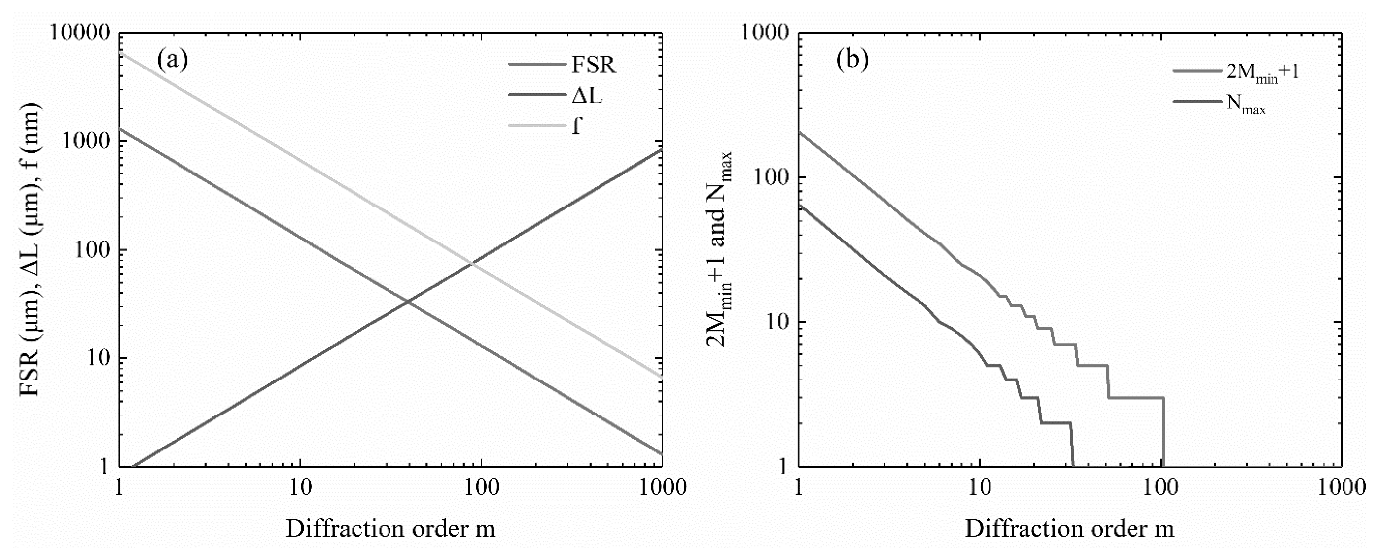
Figure 1. (a) Relations between the diffraction order m and the length difference of adjacent arrayed waveguides ΔL, focal length of slabs f, and FSR. (b) Relations between the diffraction order m and the maximum number of I/O channels Nmax and the minimum number of arrayed waveguides 2Mmin + 1.
Polymers 12 00629 g001
Figure 2. Layout schematic of the fabricated AWG device.
Polymers 12 00629 g002
Figure 3. The simulated transmission spectrum of the AWG.
Polymers 12 00629 g003
Figure 4. The fabrication process of the AWG.
Polymers 12 00629 g004
Figure 5. The micrographs of the fabricated AWG: (a) the crossing diagram, (b) the overall structure diagram and (c,d) partial enlarged diagram of the fabricated AWG.
Polymers 12 00629 g005
Figure 6. Near-field guided-mode patterns of the AWG.
Polymers 12 00629 g006
Figure 7. (a) The measured transmission spectrum of the AWG; (b) The peak wavelength and insertion loss of 5 channels.
Polymers 12 00629 g007
Table 1. Design parameters of 5 × 5 arrayed waveguide grating (AWG).
Number of Channels5
Central Wavelength (nm)1311
Channel Spacing (nm)20
Core Size (μm2) 3 × 3
Free Spectral Range (nm)118.18
Diffraction Order11
Orientation Angle (deg)30
Spacing of Arrayed and Input/Output Waveguides (μm)9.25
Path Length Difference ∆L (μm)9.30
Number of Arrayed Waveguide25