Techniques and Processes for the Realization of Electrically Conducting Textile Materials from Intrinsically Conducting Polymers and Their Application Potential


Abstract
:
1. Introduction
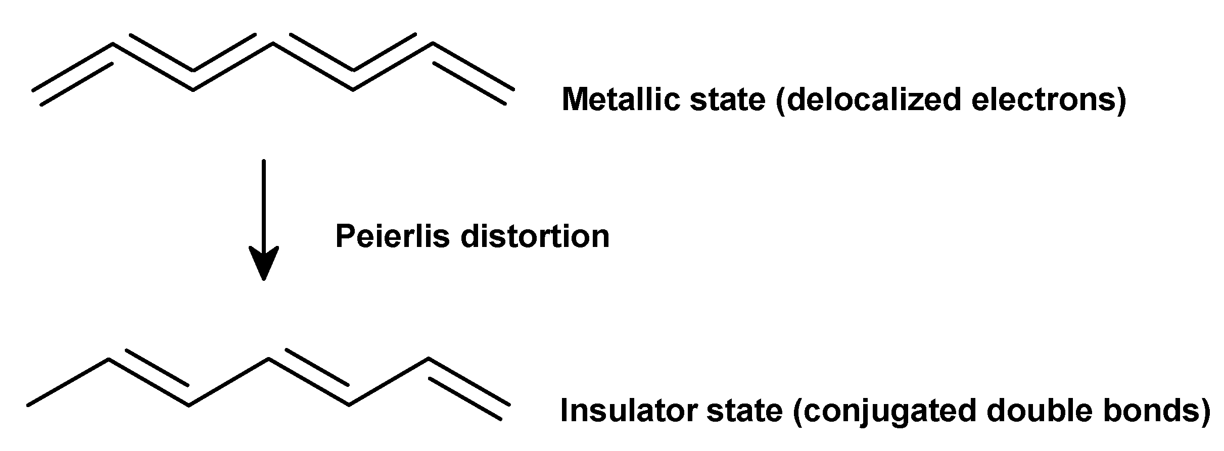
2. Electrical Conductivity of ICP
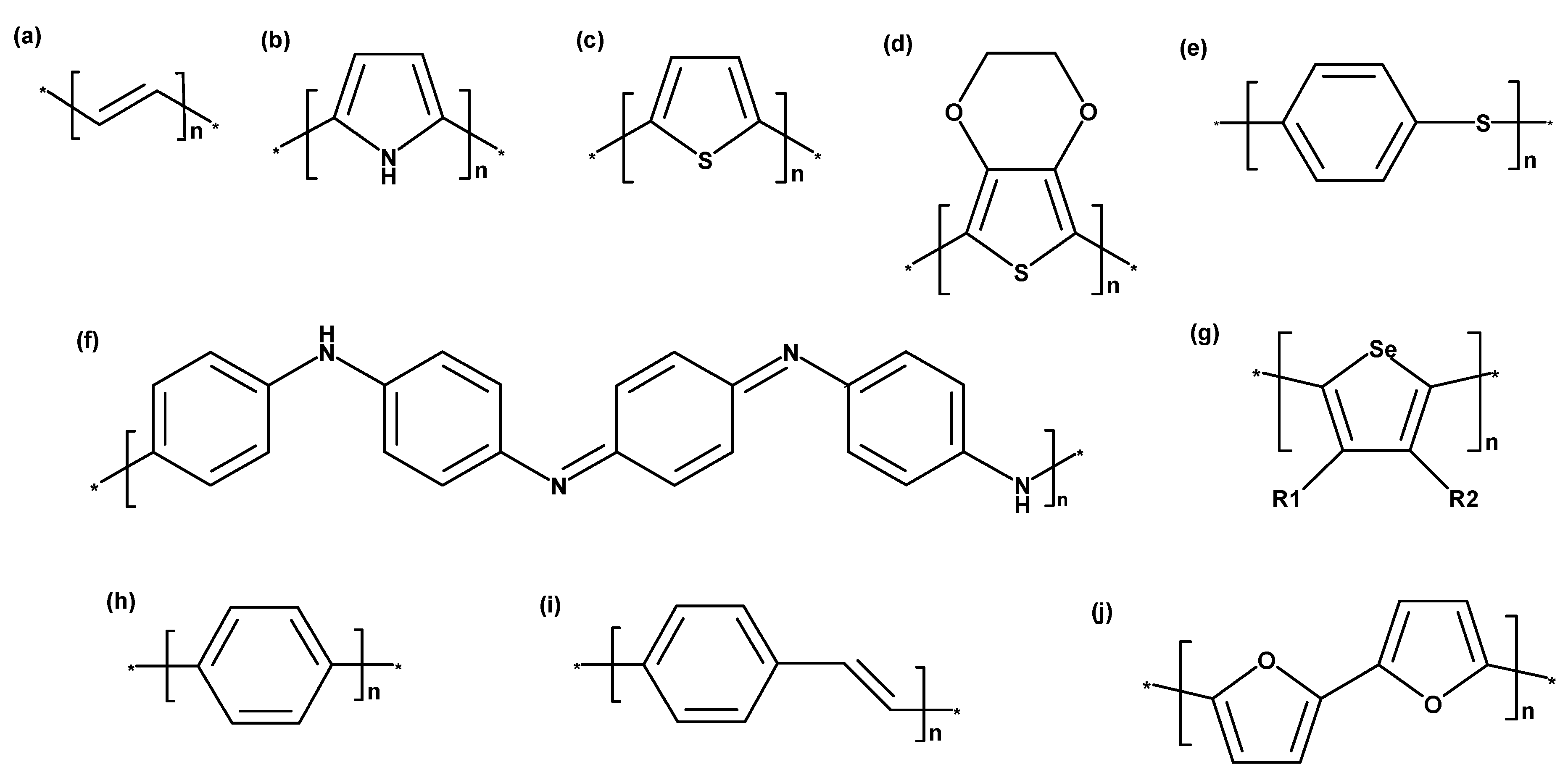
3. Intrinsically Conducting Polymer Types
3.1. Poly(Acetylene)
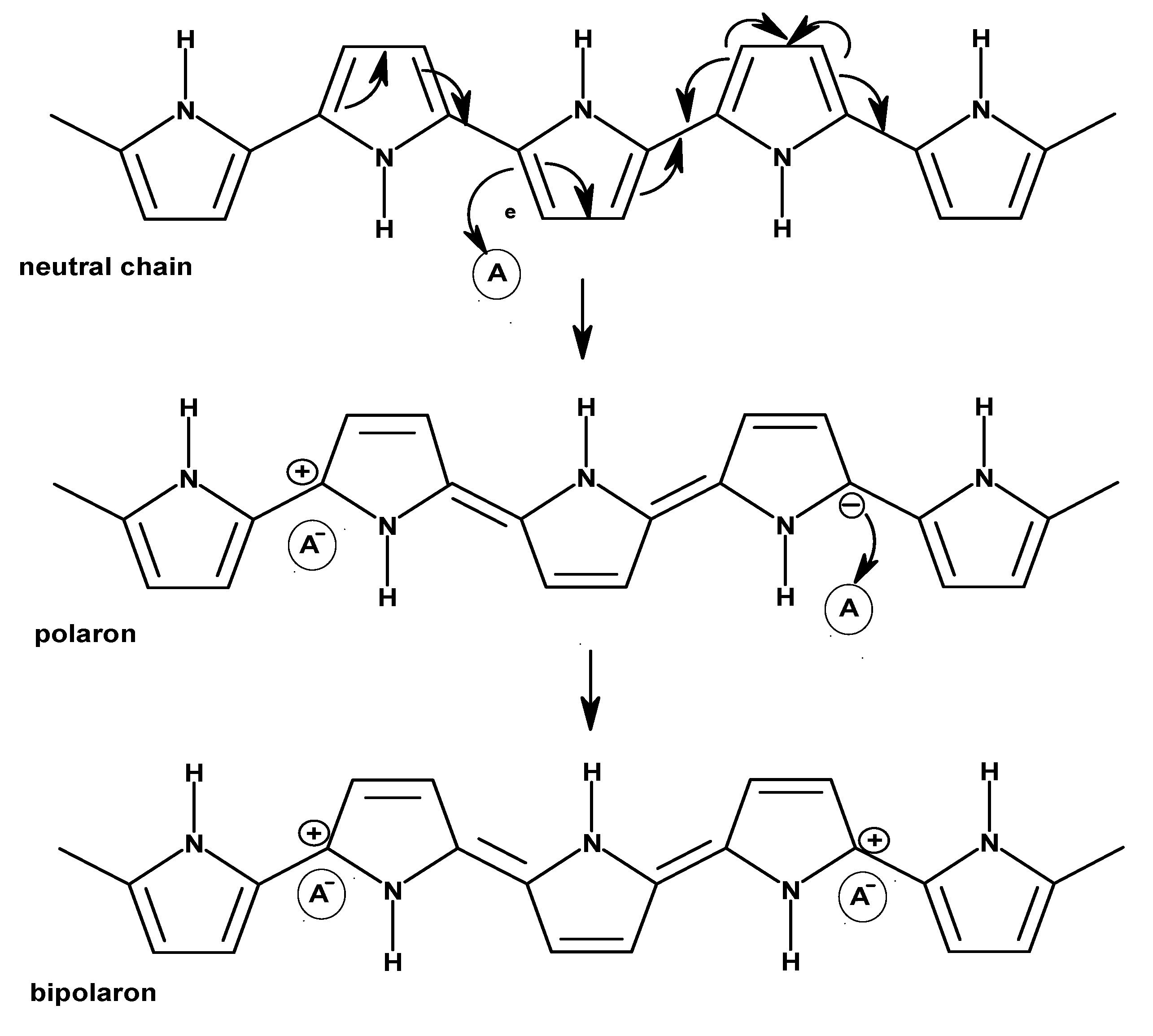
3.2. Polypyrrole
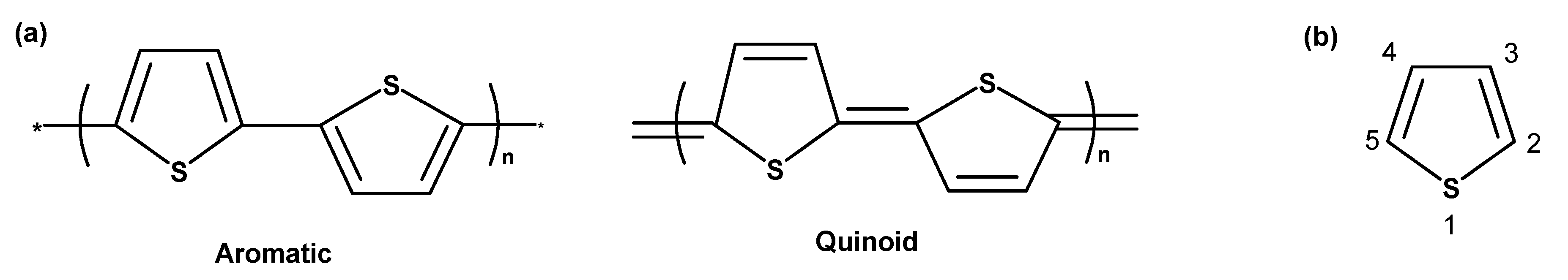
3.3. Polythiophene
3.4. Poly(3,4-Ethylenedioxythiophene)
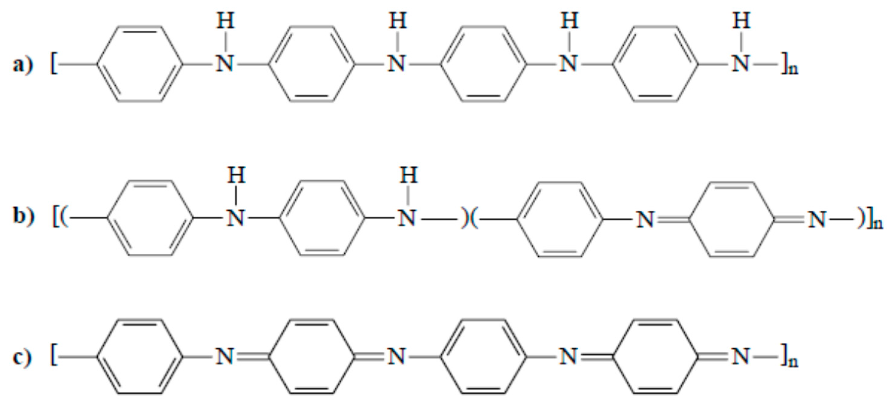
3.5. Polyaniline
- Light yellow/colorless oxidation state: reduced form of the stable “green polymer”, quickly oxidizes when exposed to air, non-conducting (Figure 7a).
- Blue oxidation state: stable form of the polymer, neutral non-conducting form; can be generated from the “green” type of PAni by neutralization using bases (Figure 7b).
- Green oxidation state: most stable form of the polymer. This form of oxidation is the most commonly used oxidation state of PAni; called conducting or organic metal (Figure 7c).
3.6. Poly(Para-Phenylene)
3.7. Poly(Para-Phenylene Vinylene)
3.8. Polyfuran
4. Methods and Procedures
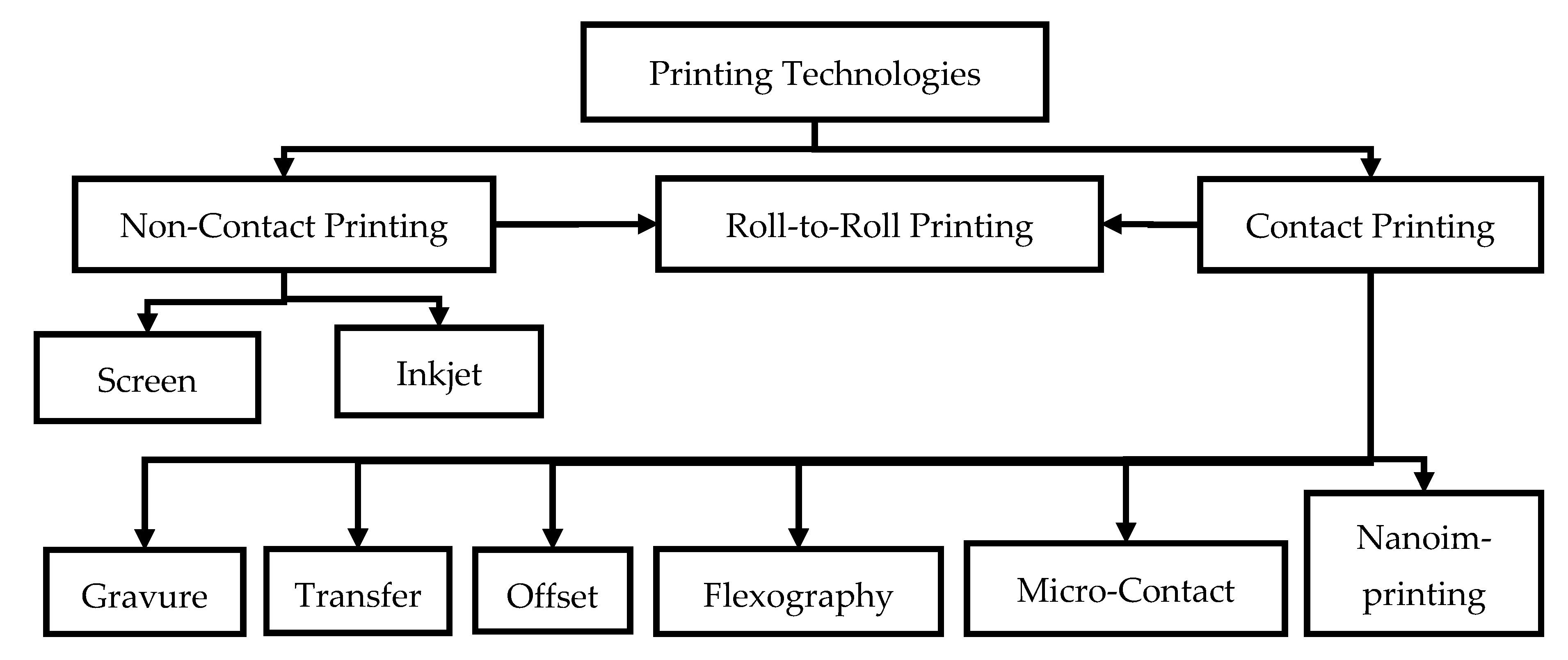
4.1. Printing Technologies
4.1.1. Screen Printing
4.1.2. Inkjet Printing
4.1.3. Gravure Printing
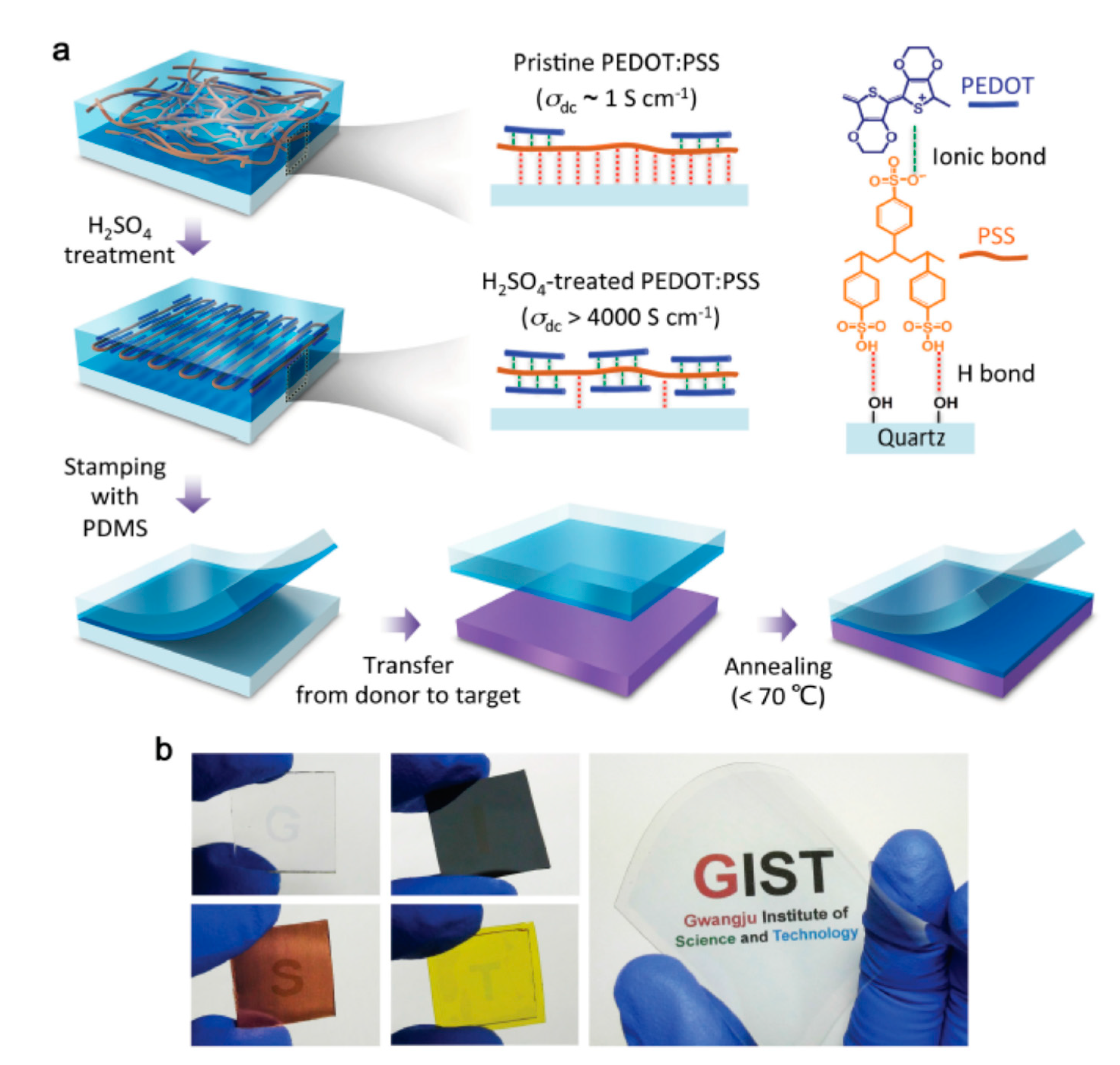
4.1.4. Transfer Printing
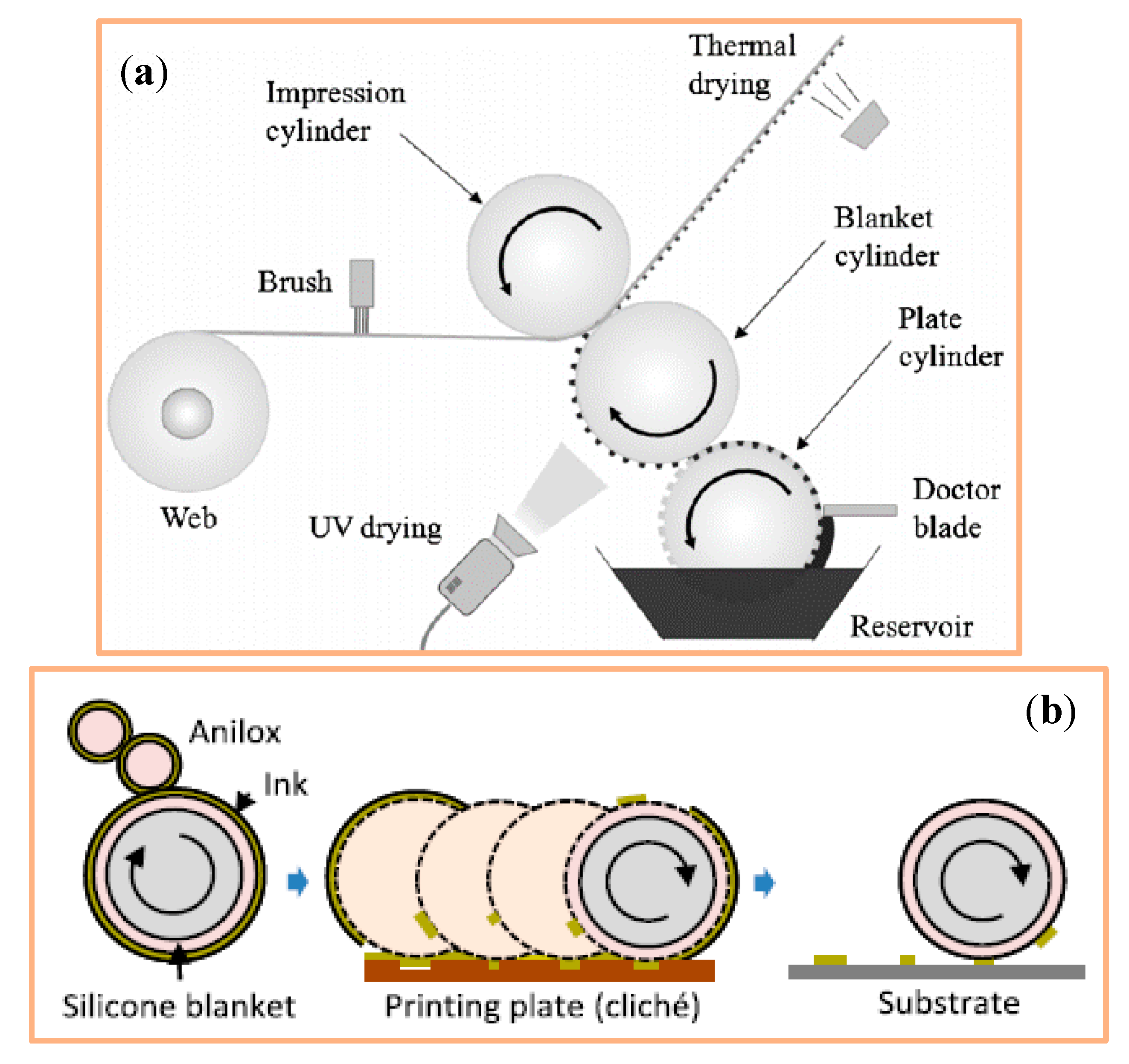
4.1.5. Offset Printing
4.1.6. Flexography
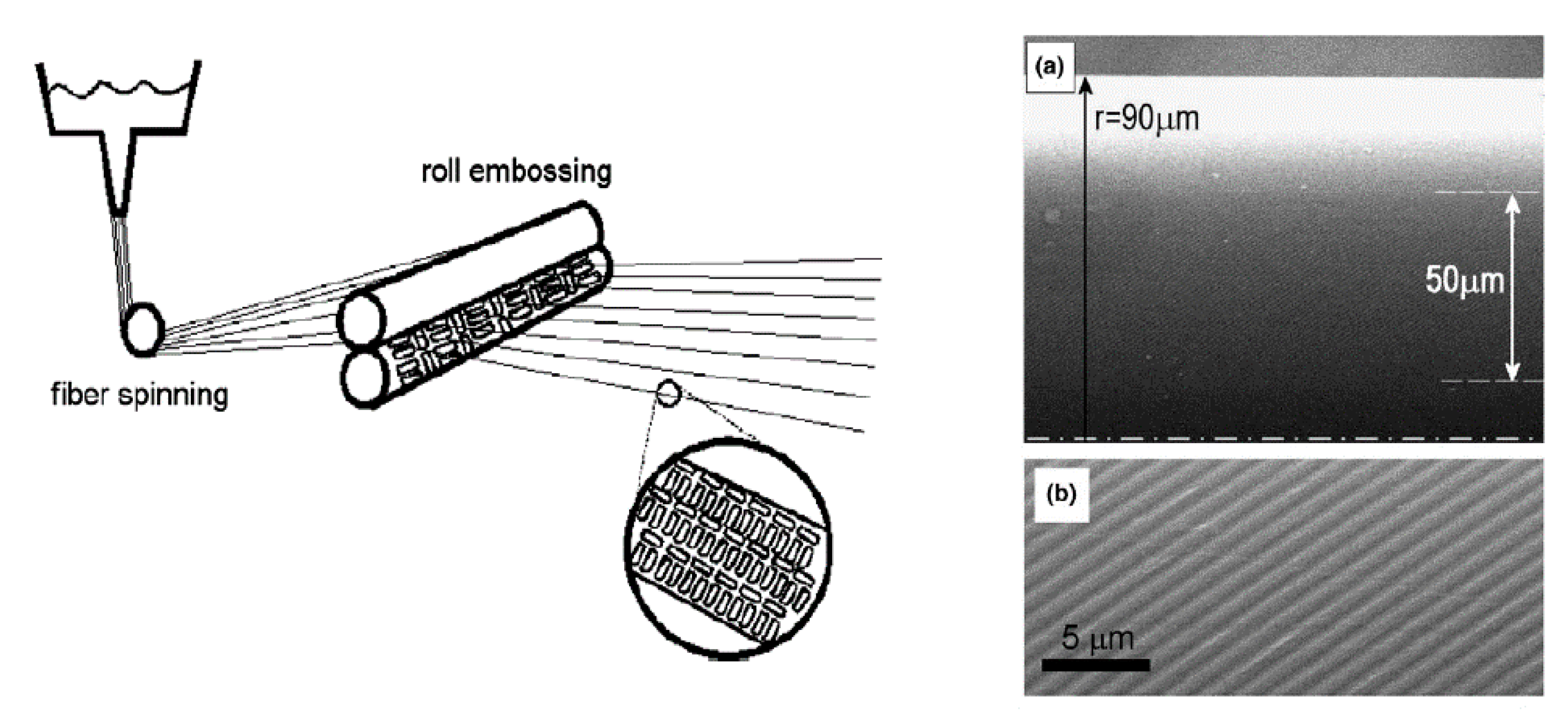
4.1.7. Nanoimprinting
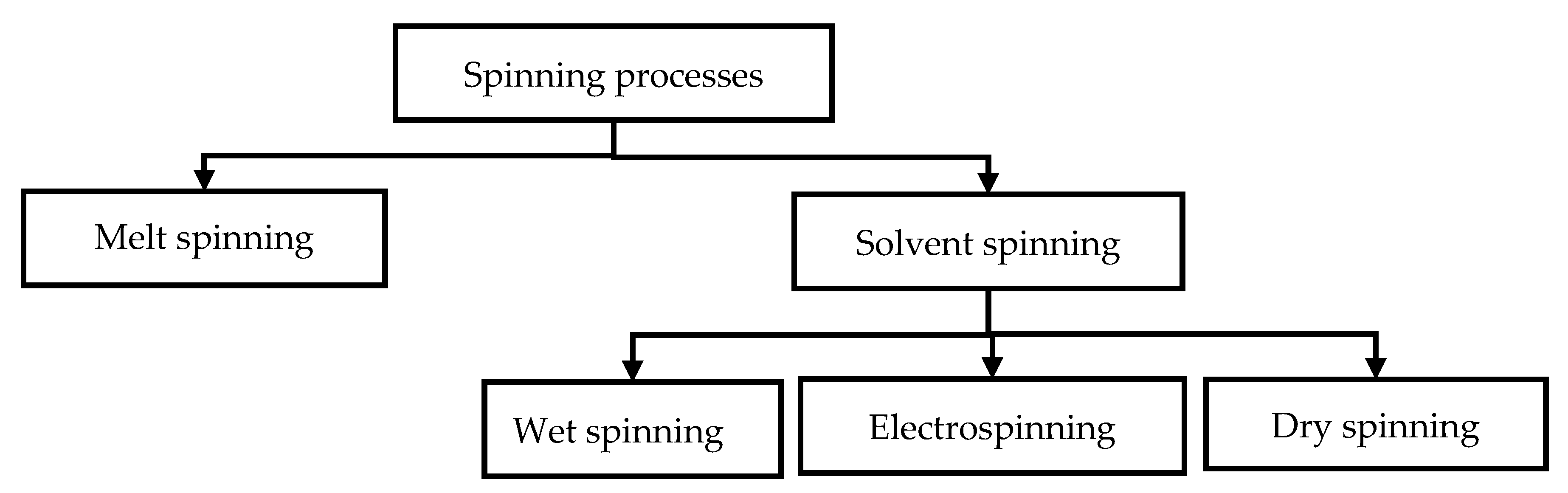
4.2. Fiber Spinning
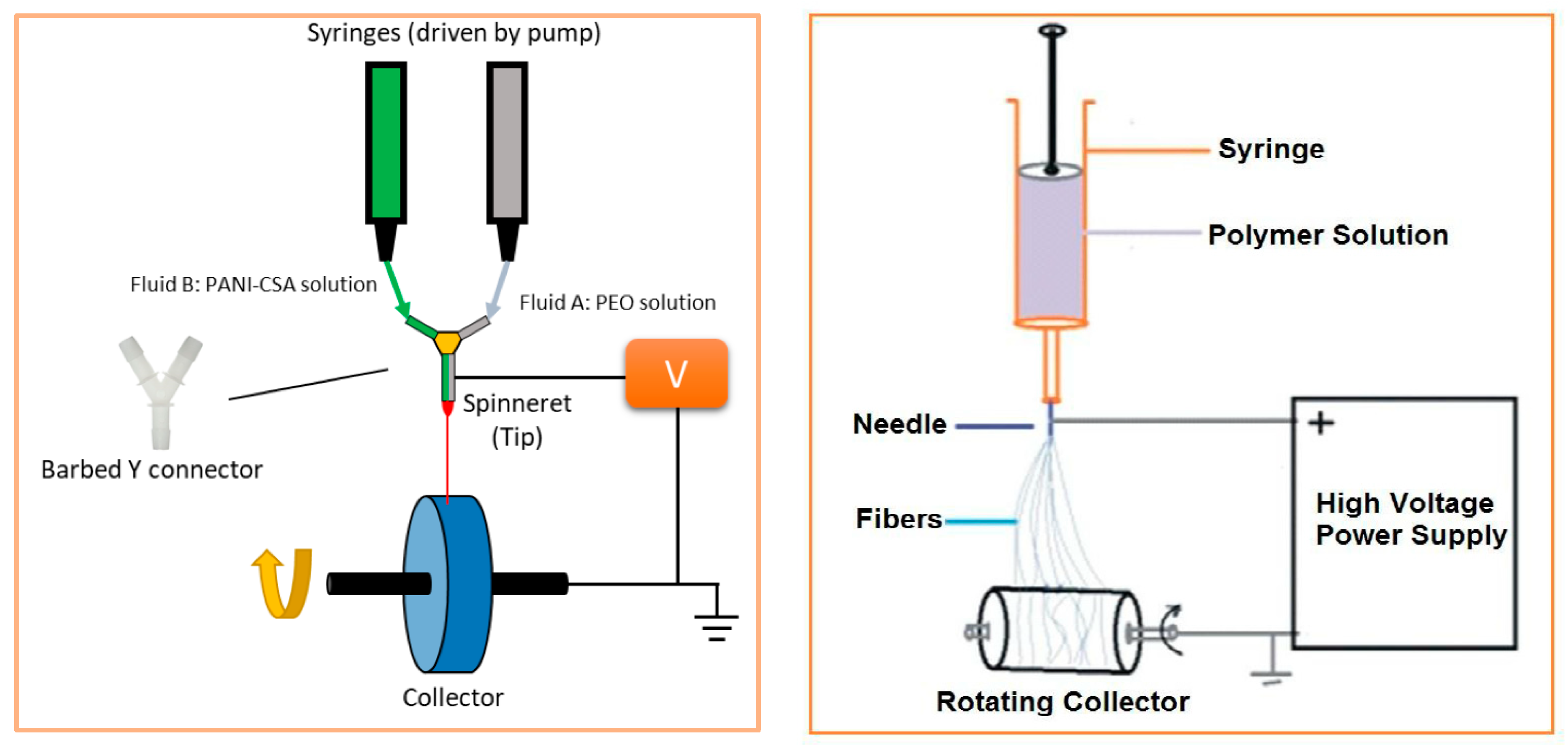
4.2.1. Electrospinning
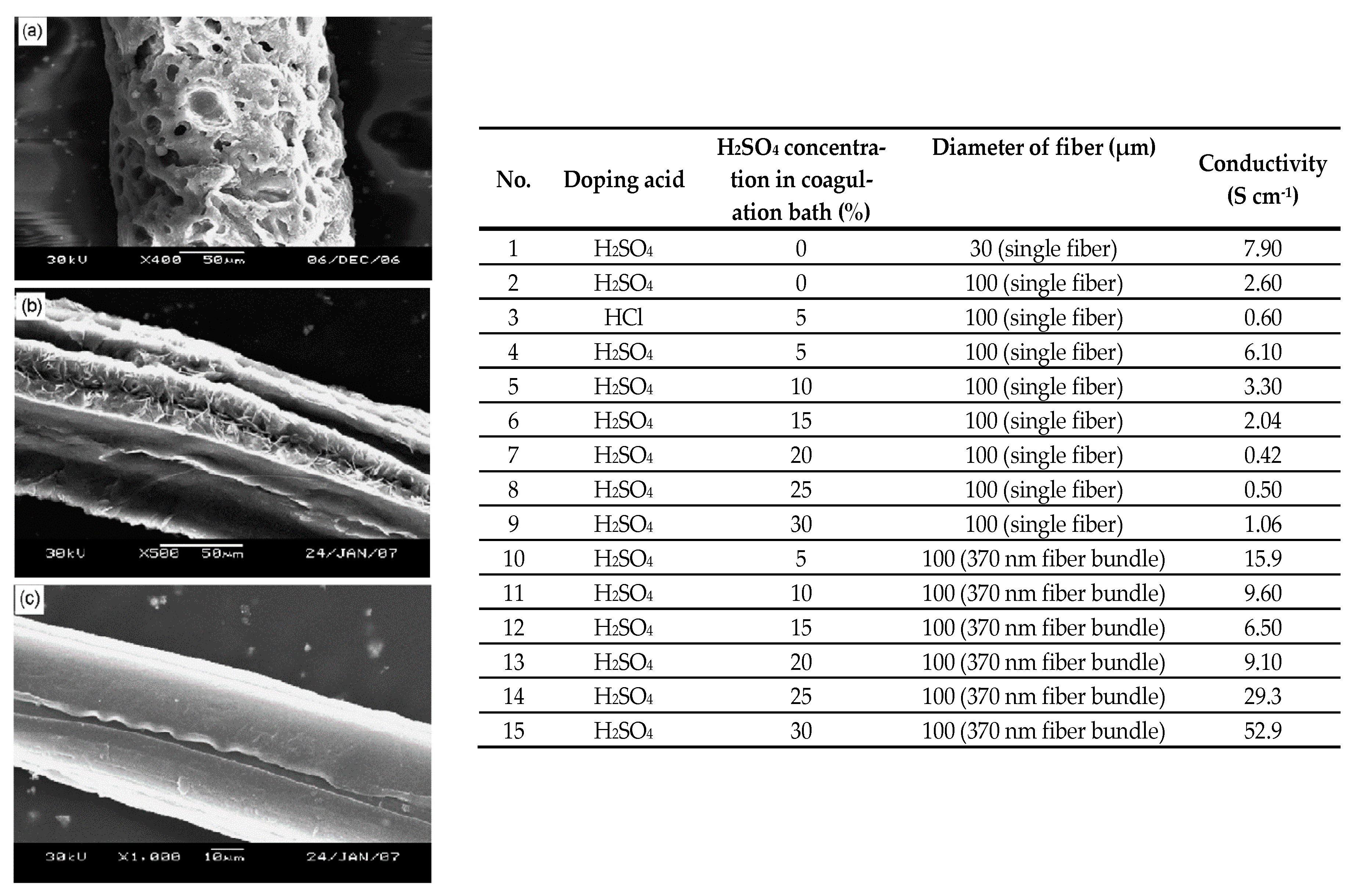
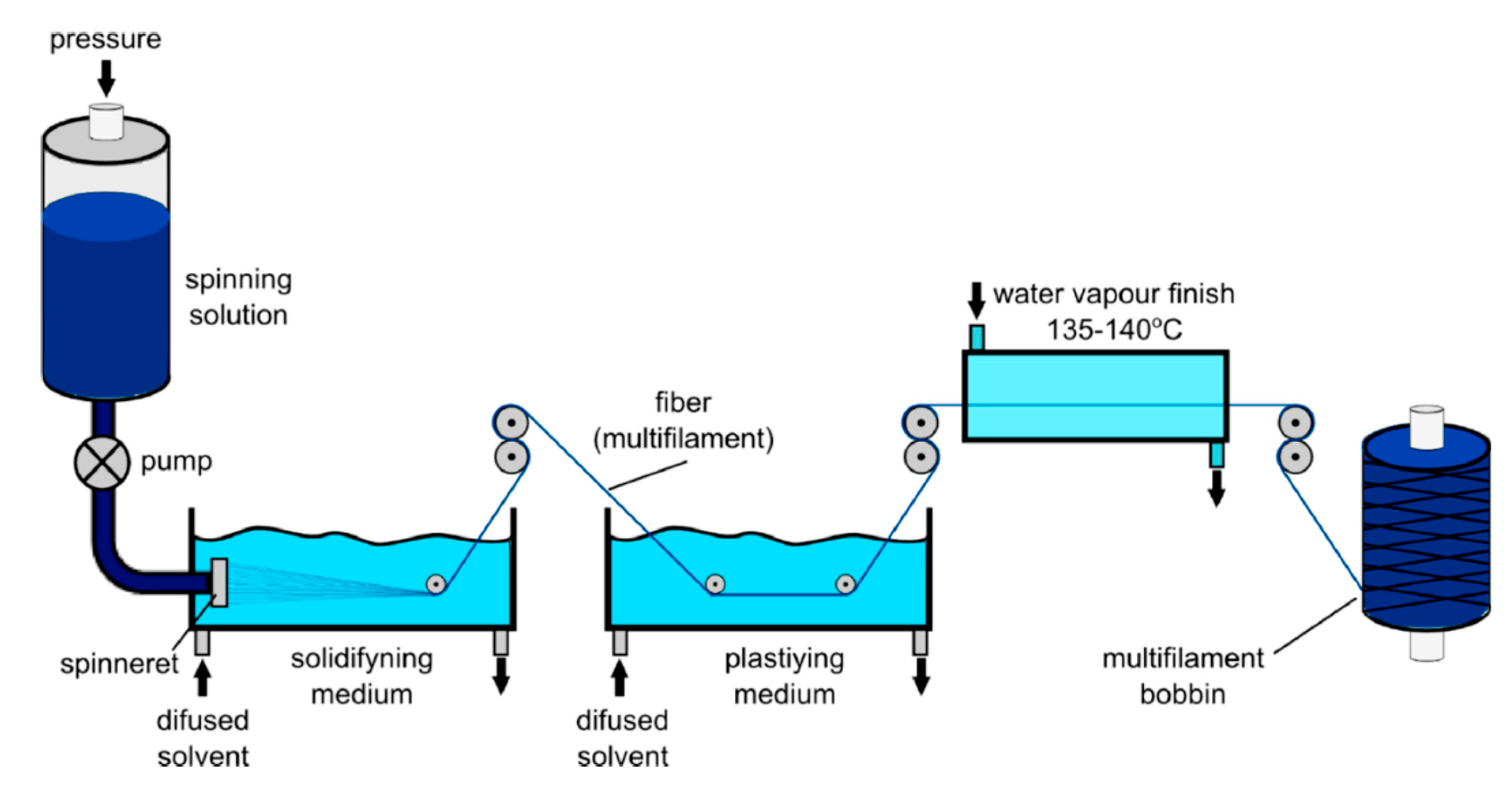
4.2.2. Wet Spinning
4.2.3. Melt Spinning
4.3. Finishing and Coating
4.3.1. Dipping-and-Drying Technique
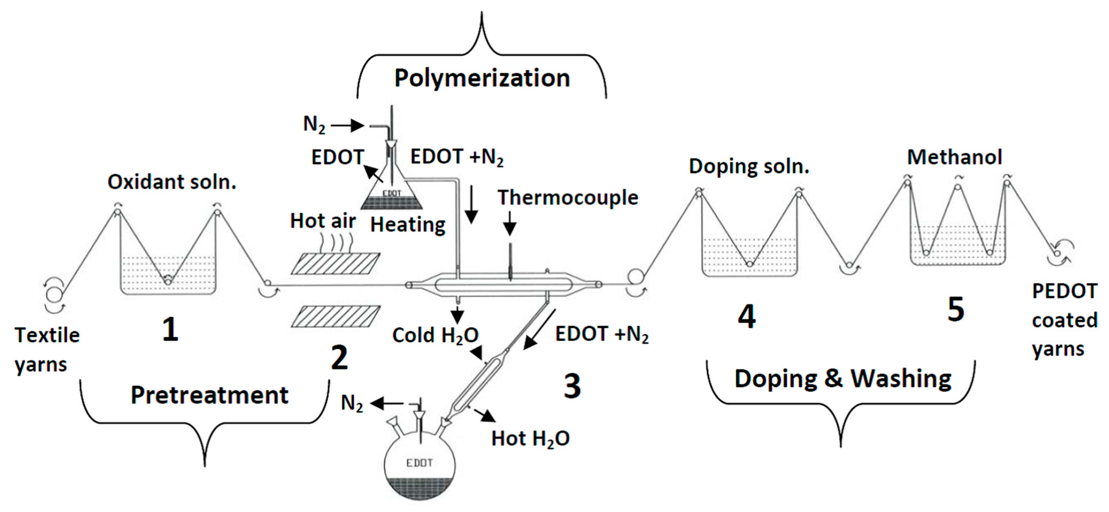
4.3.2. Chemical Solution/Vapor Polymerization
5. Applications
5.1. Electronic Components
5.1.1. Batteries and Accumulators
5.1.2. Light-Emitting Diodes
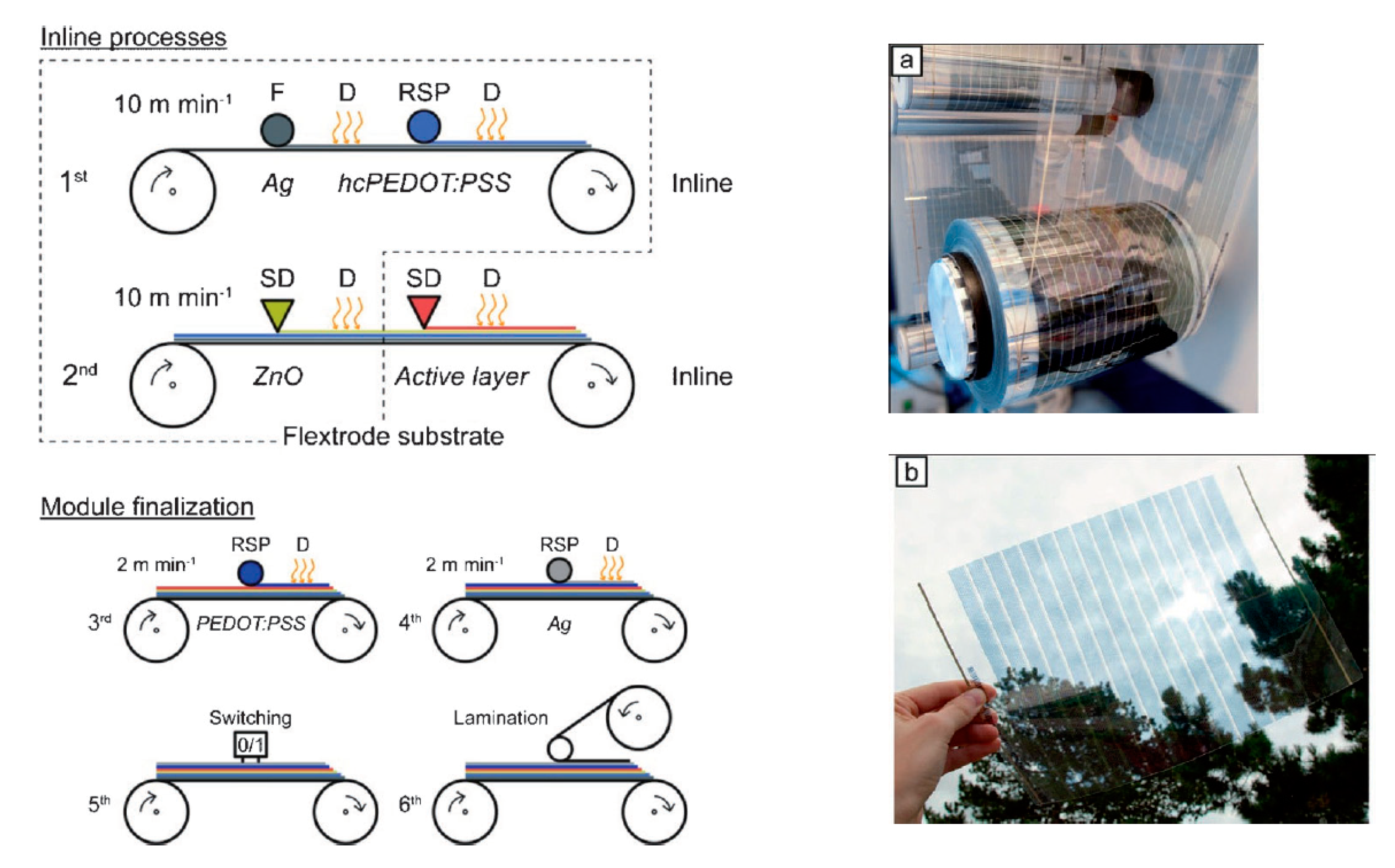
5.1.3. Solar Cells
5.1.4. Smart Windows
5.1.5. Supercapacitors
5.2. Sensors
5.2.1. Sensors for Organic Compounds
5.2.2. Biosensors and Hydrogels
5.3. Protective Coating
6. Conclusions und Outlook
Author Contributions
Funding
Conflicts of Interest
References
- Wiesbrock, F.; Griesser, T. Leitfähige Polymere. Polym. Plus Lucis 2016, 1, 49–51. [Google Scholar]
- Leute, U. Elektrisch Leitfähige Polymerwerkstoffe, 1st ed.; Springer Vieweg: Wiesbaden, Germany, 2015; p. 25. [Google Scholar]
- Mair, H.-J.; Roth, S. Elektrisch Leitende Kunststoffe, 2nd ed.; Hanser: München, Germany, 1989; pp. 253–263. ISBN1 3446156070. ISBN2 9783446156074. [Google Scholar]
- Heinze, J. Electronically Conducting Polymers; Springer: Berlin/Heidelberg, Germany, 1990; Volume 152, pp. 1–47. ISBN 3-540-51461-9. [Google Scholar]
- Skotheim, T.A. Handbook of Conducting Polymers, 2nd ed.; Marcel Dekker, Inc.: New York, NY, USA, 1998; pp. 259–277. ISBN1 0824700503. ISBN2 9780824700508. [Google Scholar]
- Perez, P.N.G.; Sino, P.A.L.; Herrera, M.U.; Tapia, A.K.G. Conducting Properties of Polyaniline Emeraldine Salt on Paper in the Low-Frequency Region. Mater. Sci. Forum 2018, 923, 72–76. [Google Scholar] [CrossRef]
- Schopf, G.; Koßmehl, G. Electrically Conductive Molecules and Polymers; Springer: Berlin/Heidelberg, Germany, 1997; pp. 1–166. [Google Scholar]
- Roemer, M. Elektrochemo-und Mikromechanisches Verhalten Elektronisch Leitfähiger Polymere. Ph.D. Thesis, Naturwissenschaftender Universität Kassel, Kassel, Germany, 2004. [Google Scholar]
- Crimmann, P. Grenzflächenmodifizierung und–Analyse im Polypropylen-Kupfer-Verbund. Ph.D. Thesis, Martin-Luther-Universität Halle-Wittenberg, Halle Saale, Germany, 2003. [Google Scholar]
- Saidmann, S.B. Influence of anion and pH on the electrochemical behaviour of polypyrrole synthesised in alkaline media Electrochim. Acta 2003, 48, 1719–1726. [Google Scholar]
- Chauvet, O.; Paschen, S.; Forro, L.; Zuppiroli, L.; Bujard, P.; Kai, K.; Wernet, W. Magnetic and transport properties of polypyrrole doped with polyanions. Synth. Met. 1994, 63, 115–119. [Google Scholar] [CrossRef]
- Bredas, J.L.; Street, G.B. Polarons, bipolarons, and solitons in conducting polymers. Accounts Chem. Res. 1985, 18, 309–315. [Google Scholar] [CrossRef]
- Wrubbel, N.M. Elektrisch Leitfähige Polymere auf Basis von Flüssigkristallinen Thiophenderivaten. Synthese, Charakterisierung, Polymerisation, Ordnungdeffekte. Ph.D. Thesis, Heinrich-Heine-Universität Düsseldorf, Düsseldorf, Germany, 2004. [Google Scholar]
- François, B.; Olinga, T. Polystyrene-polythiophene block copolymers (PS-PT) synthesis, characterization and doping. Synth. Met. 1993, 57, 3489. [Google Scholar] [CrossRef]
- Schneider, M. Polythiophene als Sensitive Filme in Chemischen Sensoren. Ph.D. Thesis, Technische Universität Dresden, Dresden, Germany, 2002. [Google Scholar]
- Marr, I.; Stöcker, T.; Moos, R. F3-Resistives Gasdosimeter auf Basis von PEDOT/PSS zur Detektion von NO und NO2. Tagungsband 2013, 11, 317–320. [Google Scholar] [CrossRef]
- Lange, U.; Mirsky, V.M. Leitfähige polymere in Chemo-und Biosensoren. Anal. Chim. Acta 2011, 687, 105–113. [Google Scholar] [CrossRef]
- Regent PEOT’s Information. Available online: https://de.vwr.com/store/product?keyword=PEOT (accessed on 12 November 2020).
- Manding, K.V.S.; Lopez, J.E.S.; Tapia, A.K.G. AC Conduction in Polyaniline Emeraldine Salt-Graphite Pellets. Mater. Sci. Forum 2018, 923, 66–71. [Google Scholar] [CrossRef]
- Tiitu, M. Towards Printed Electronic Devices Large-Scale Processing Methods for Conducting Polyaniline. Ph.D. Thesis, Helsinki University of Technology, Finland, 2006. [Google Scholar]
- González-Tejera, M.; De La Blanca, E.S.; Carrillo, I. Polyfuran conducting polymers: Synthesis, properties, and applications. Synth. Met. 2008, 158, 165–189. [Google Scholar] [CrossRef] [Green Version]
- Ngamna, O.; Morrin, A.; Killard, A.J.; Moulton, S.E.; Smyth, M.R.; Wallace, G.G. Inkjet Printable Polyaniline Nanoformulations. Langmuir 2007, 23, 8569–8574. [Google Scholar] [CrossRef] [PubMed]
- Takamatsu, S.; Lonjaret, T.; Crisp, D.; Badier, J.-M.; Malliaras, G.G.; Ismailova, E. Direct patterning of organic conductors on knitted textiles for long-term electrocardiography. Sci. Rep. 2015, 5, 15003. [Google Scholar] [CrossRef] [PubMed] [Green Version]
- Urbaniak-Domagała, W.; Skrzetuska, E.; Komorowska, M.; Krucinska, I. Development Trends in Electronics Printed: Intelligent Textiles Produced with the Use of Printing Techniques on Textile Substrates. Print. Electron. Curr. Trends Appl. 2016, 7, 115–137. [Google Scholar] [CrossRef]
- Jonas, F.; Guntermann, U.; Bayer, A.G. Screen Printing Paste for Producing Electrically Conductive Coatings. U.S. Patent 6,358,437, 19 March 2002. [Google Scholar]
- Victor, J.G.; Wilkinson, M.; Carter, S. Screen Printing Light-Emitting Polymer Patterned Devices. US Patent 6,605,483, 12 August 2003. [Google Scholar]
- Rubežienė, V.; Abraitienė, A.; Baltušnikaitė-Guzaitienė, J.; Varnaitė-Žuravliova, S.; Sankauskaitė, A.; Kancleris, Ž.; Ragulis, P.; Šlekas, G. The influence of distribution and deposit of conductive coating on shielding effectiveness of textiles. J. Text. Inst. 2018, 109, 358–367. [Google Scholar] [CrossRef]
- Åkerfeldt, M.; Lund, A.; Walkenström, P. Textile sensing glove with piezoelectric PVDF fibers and printed electrodes of PEDOT: PSS. Text. Res. J. 2015, 85, 1789–1799. [Google Scholar] [CrossRef]
- Di Risio, S.; Yan, N. Piezoelectric Ink-Jet Printing of Horseradish Peroxidase: Effect of Ink Viscosity Modifiers on Activity. Macromol. Rapid Commun. 2007, 28, 1934–1940. [Google Scholar] [CrossRef]
- De Gans, B.B.-J.; Schubert, U.S. Inkjet Printing of Polymer Micro-Arrays and Libraries: Instrumentation, Requirements, and Perspectives. Macromol. Rapid Commun. 2003, 24, 659–666. [Google Scholar] [CrossRef]
- Sawhney, A.; Agrawal, A.; Patra, P.; Calvert, P. Piezoresistive Sensors on Textiles by Inkjet Printing and Electroless Plating. MRS Proc. 2006, 920, 103–106. [Google Scholar] [CrossRef] [Green Version]
- Sawhney, A.; Agrawal, A.; Lo, T.C.; Patra, P.K.; Chen, C.H.; Calvert, P. Soft-structured sensors and connectors by Inkjet Printing. AATCC Rev. 2007, 7, 1–10. [Google Scholar]
- Calvert, P.; Patra, P.; Sawhney, A.; Agrawal, A.; Duggal, D. Printed conducting polymer strain sensors for textiles. In Proceedings of the NIP & Digital Fabrication Conference, Anchorage, Alaska, NY, USA, 16 September 2007; Society for Imaging Science and Technology: Springfield, VA, USA, 2007; pp. 831–835. [Google Scholar]
- Calvert, P.; Duggal, D.; Patra, P.; Agrawal, A.; Sawhney, A. Conducting Polymer and Conducting Composite Strain Sensors on Textiles. Mol. Cryst. Liq. Cryst. 2008, 484, 291/[657]–302/[668]. [Google Scholar] [CrossRef]
- Bocchini, S.; Castellino, M.; Della Pina, C.; Rajan, K.; Falletta, E.; Chiolerio, A. Inkjet printed doped polyaniline: Navigating through physics and chemistry for the next generation devices. Appl. Surf. Sci. 2018, 456, 246–258. [Google Scholar] [CrossRef] [Green Version]
- Mhetre, S.; Carr, W.; Radhakrishnaiah, P. On the relationship between ink-jet printing quality of pigment ink and the spreading behavior of ink drops. J. Text. Inst. 2010, 101, 423–430. [Google Scholar] [CrossRef]
- Liu, S.; Liu, D.; Pan, Z.-J. The Effect of Polyaniline (PANI) Coating via Dielectric-Barrier Discharge (DBD) Plasma on Conductivity and Air Drag of Polyethylene Terephthalate (PET) Yarn. Polymers 2018, 10, 351. [Google Scholar] [CrossRef] [PubMed] [Green Version]
- Setti, L.; Fraleoni-Morgera, A.; Ballarin, B.; Filippini, A.; Frascaro, D.; Piana, C. An amperometric glucose biosensor prototype fabricated by thermal inkjet printing. Biosens. Bioelectron. 2005, 20, 2019–2026. [Google Scholar] [CrossRef] [PubMed]
- Hu, X.; Chen, L.; Ji, T.; Zhang, Y.; Hu, A.; Wu, F.; Li, G.; Chen, Y. Roll-to-Roll Production of Graphene Hybrid Electrodes for High-Efficiency, Flexible Organic Photoelectronics. Adv. Mater. Interfaces 2015, 2, 1500445. [Google Scholar] [CrossRef]
- Starck GmbH, H.C. Screen Printing Paste for Producing Electrically Conductive Coatings. European Patent EP 1 042 755 B9, 30 November 2006. [Google Scholar]
- Kim, N.; Kang, H.; Lee, J.-H.; Kee, S.; Lee, S.H.; Lee, K. Highly Conductive All-Plastic Electrodes Fabricated Using a Novel Chemically Controlled Transfer-Printing Method. Adv. Mater. 2015, 27, 2317–2323. [Google Scholar] [CrossRef]
- Kang, H.W.; Sung, H.J.; Lee, T.-M.; Kim, D.-S.; Kim, C.-J. Liquid transfer between two separating plates for micro-gravure-offset printing. J. Micromech. Microeng. 2009, 19, 015025. [Google Scholar] [CrossRef] [Green Version]
- Choi, N.; Wee, H.; Nam, S.; Lavelle, J.; Hatalis, M. A modified offset roll printing for thin film transistor applications. Microelectron. Eng. 2012, 91, 93–97. [Google Scholar] [CrossRef]
- Hösel, M.; Søndergaard, R.R.; Jørgensen, M.; Krebs, F.C. Fast Inline Roll-to-Roll Printing for Indium-Tin-Oxide-Free Polymer Solar Cells Using Automatic Registration. Energy Technol. 2013, 1, 102–107. [Google Scholar] [CrossRef]
- Schift, H.; Halbeisen, M.; Schütz, U.; Delahoche, B.; Vogelsang, K.; Gobrecht, J. Surface structuring of textile fibers using roll embossing. Microelectron. Eng. 2006, 83, 855–858. [Google Scholar] [CrossRef]
- Hsu, C.-H.; Shih, H.; Subramoney, S.; Epstein, A. High tenacity, high modulus conducting polyaniline composite fibers. Synth. Met. 1999, 101, 677–680. [Google Scholar] [CrossRef]
- Yu, Q.-Z.; Shi, M.; Deng, M.; Wang, M.; Chen, H. Morphology and conductivity of polyaniline sub-micron fibers prepared by electrospinning. Mater. Sci. Eng. B 2008, 150, 70–76. [Google Scholar] [CrossRef]
- Zhang, Y.; Rutledge, G.C. Electrical Conductivity of Electrospun Polyaniline and Polyaniline-Blend Fibers and Mats. Macromolecules 2012, 45, 4238–4246. [Google Scholar] [CrossRef] [Green Version]
- Liu, W.; Zhang, J.; Liu, H. Conductive Bicomponent Fibers Containing Polyaniline Produced via Side-by-Side Electrospinning. Polymers 2019, 11, 954. [Google Scholar] [CrossRef] [Green Version]
- Khan, A.; Kordesch, M.; Khan, S. Conducting Polymer Fibers of Polyaniline Doped with Camphorsulfonic Acid; MRS Online Proceedings Library Archive; Published online by Cambridge University Press: Cambrige, UK, 2006; Volume 948. [Google Scholar] [CrossRef]
- Wang, Q.; Yao, Q.; Chang, J.; Chen, L. Enhanced thermoelectric properties of CNT/PANI composite nanofibers by highly orienting the arrangement of polymer chains. J. Mater. Chem. 2012, 22, 17612–17618. [Google Scholar] [CrossRef]
- Shin, M.K.; Kim, Y.J.; Kim, S.; Lee, H.; Spinks, G.M. Enhanced conductivity of aligned PANi/PEO/MWNT nanofibers by electrospinning. Sens. Actuators B Chem. 2008, 134, 122–126. [Google Scholar] [CrossRef]
- Nimkar, S.H.; Agrawal, S.P.; Kondawar, S.B. Fabrication of Electrospun Nanofibers of Titanium Dioxide Intercalated Polyaniline Nanocomposites for CO2 Gas Sensor. Procedia Mater. Sci. 2015, 10, 572–579. [Google Scholar] [CrossRef] [Green Version]
- Oueiny, C.; Berlioz, S.; Perrin, F.-X. Carbon nanotube–polyaniline composites. Prog. Polym. Sci. 2014, 39, 707–748. [Google Scholar] [CrossRef]
- Hu, X.; Wang, X.; Liu, J.; Zhang, S.; Jiang, C.; He, X. Fabrication of mesoporous dendritic silica nanofibers by using dendritic polyaniline templates. Mater. Chem. Phys. 2012, 137, 17–21. [Google Scholar] [CrossRef]
- Wei, M.; Lee, J.; Kang, B.; Mead, J. Preparation of Core-Sheath Nanofibers from Conducting Polymer Blends. Macromol. Rapid Commun. 2005, 26, 1127–1132. [Google Scholar] [CrossRef]
- Yu, G.; Li, X.; Cai, X.; Cui, W.; Zhou, S.; Weng, J. The photoluminescence enhancement of electrospun poly(ethylene oxide) fibers with CdS and polyaniline inoculations. Acta Mater. 2008, 56, 5775–5782. [Google Scholar] [CrossRef]
- Zhao, W.; Yalcin, B.; Cakmak, M. Dynamic assembly of electrically conductive PEDOT:PSS nanofibers in electrospinning process studied by high speed video. Synth. Met. 2015, 203, 107–116. [Google Scholar] [CrossRef]
- Liu, N.; Fang, G.; Wan, J.; Zhou, H.; Long, H.; Zhao, X. Electrospun PEDOT:PSSPVA nanofiber based ultrahigh-strain sensors with controllable electrical conductivity. J. Mater. Chem. 2011, 21, 18962–18966. [Google Scholar] [CrossRef]
- Ketpang, K.; Park, J.S. Electrospinning PVDF/PPy/MWCNTs conducting composites. Synth. Met. 2010, 160, 1603–1608. [Google Scholar] [CrossRef]
- Savest, N.; Plamus, T.; Kütt, K.; Kallavus, U.; Viirsalu, M.; Tarasova, E.; Vassiljeva, V.; Krasnou, I.; Krumme, A. Electrospun conductive mats from PANi-ionic liquid blends. J. Electrost. 2018, 96, 40–44. [Google Scholar] [CrossRef]
- Lee, S.; Moon, G.D.; Jeong, U. Continuous production of uniform poly(3-hexylthiophene) (P3HT) nanofibers by electrospinning and their electrical properties. J. Mater. Chem. 2009, 19, 743–748. [Google Scholar] [CrossRef]
- Gao, Q.; Meguro, H.; Okamoto, S.; Kimura, M. Flexible Tactile Sensor Using the Reversible Deformation of Poly(3-hexylthiophene) Nanofiber Assemblies. Langmuir 2012, 28, 17593–17596. [Google Scholar] [CrossRef]
- Lee, J.Y.; Bashur, C.A.; Goldstein, A.S.; Schmidt, C. Polypyrrole-coated electrospun PLGA nanofibers for neural tissue applications. Biomaterials 2009, 30, 4325–4335. [Google Scholar] [CrossRef] [Green Version]
- Okuzaki, H.; Ishihara, M. Spinning and Characterization of Conducting Microfibers. Macromol. Rapid Commun. 2003, 24, 261–264. [Google Scholar] [CrossRef]
- Okuzaki, H.; Harashina, Y.; Yan, H. Highly conductive PEDOT/PSS microfibers fabricated by wet-spinning and dip-treatment in ethylene glycol. Eur. Polym. J. 2009, 45, 256–261. [Google Scholar] [CrossRef]
- Jalili, R.; Razal, J.M.; Innis, P.C.; Wallace, G.G. One-Step Wet-Spinning Process of Poly(3,4-ethylenedioxythiophene):Poly(styrenesulfonate) Fibers and the Origin of Higher Electrical Conductivity. Adv. Funct. Mater. 2011, 21, 3363–3370. [Google Scholar] [CrossRef]
- Jalili, R.; Razal, J.M.; Wallace, G.G. Wet-spinning of PEDOT:PSS/Functionalized-SWNTs Composite: A Facile Route Toward Production of Strong and Highly Conducting Multifunctional Fibers. Sci. Rep. 2013, 3, 3438. [Google Scholar] [CrossRef] [PubMed] [Green Version]
- Seyedin, M.Z.; Razal, J.M.; Innis, P.C.; Wallace, G.G. Strain-Responsive Polyurethane/PEDOT:PSS Elastomeric Composite Fibers with High Electrical Conductivity. Adv. Funct. Mater. 2014, 24, 2957–2966. [Google Scholar] [CrossRef] [Green Version]
- Esrafilzadeh, D.; Razal, J.M.; Moulton, S.E.; Stewart, E.M.; Wallace, G.G. Multifunctional conducting fibres with electrically controlled release of ciprofloxacin. J. Control. Release 2013, 169, 313–320. [Google Scholar] [CrossRef] [PubMed] [Green Version]
- Wang, Z.; Cheng, J.; Guan, Q.; Huang, H.; Li, Y.; Zhou, J.; Ni, W.; Wang, B.; He, S.; Peng, H. All-in-one fiber for stretchable fiber-shaped tandem supercapacitors. Nano Energy 2018, 45, 210–219. [Google Scholar] [CrossRef]
- Ding, X.; Zhao, Y.; Hu, C.; Hu, Y.; Dong, Z.; Chen, N.; Zhang, Z.; Qu, L. Spinning fabrication of graphene/polypyrrole composite fibers for all-solid-state, flexible fibriform supercapacitors. J. Mater. Chem. A 2014, 2, 12355–12360. [Google Scholar] [CrossRef]
- Zhang, Q.; Jin, H.; Wang, X.; Jing, X. Morphology of conductive blend fibers of polyaniline and polyamide-11. Synth. Met. 2001, 123, 481–485. [Google Scholar] [CrossRef]
- Zhang, Q.; Wang, X.; Chen, D.; Jing, X. Preparation and properties of conductive polyaniline/poly-?-aminoundecanoyle fibers. J. Appl. Polym. Sci. 2002, 85, 1458–1464. [Google Scholar] [CrossRef]
- Foroughi, J.; Spinks, G.M.; Wallace, G.G. Effect of synthesis conditions on the properties of wet spun polypyrrole fibres. Synth. Met. 2009, 159, 1837–1843. [Google Scholar] [CrossRef]
- Li, X.; Ming, J.; Ning, X. Wet-spun conductive silk fibroin–polyaniline filaments prepared from a formic acid–shell solution. J. Appl. Polym. Sci. 2019, 47127, 1–7. [Google Scholar] [CrossRef]
- Lee, W.-P.; Brenneman, K.R.; Hsu, C.H.; Shih, H.; Epstein, A.J. Charge Transport Properties of High-Strength, High-Modulus Sulfonated Polyaniline/Poly(p-phenylene terephthalamide) Fibers. Macromolecules 2001, 34, 2648–2652. [Google Scholar] [CrossRef]
- Jiang, J.; Wei, P.; Shenglin, Y.; Li, G. Electrically conductive PANI-DBSA/Co-PAN composite fibers prepared by wet spinning. Synth. Met. 2005, 149, 181–186. [Google Scholar] [CrossRef]
- Karbownik, I.; Rac-Rumijowska, O.; Fiedot-Toboła, M.; Rybicki, T.; Teterycz, H. The Preparation and Characterization of Polyacrylonitrile-Polyaniline (PAN/PANI) Fibers. Materials 2019, 12, 664. [Google Scholar] [CrossRef] [PubMed] [Green Version]
- Giovanni, M. Limit of the Spinning Process in Anufacturing Synthetic Fibers, 1st ed.; Springer: Wien, Österreich, 1975; p. 53. ISBN 321181308X. [Google Scholar]
- Kim, B.; Koncar, V.; Devaux, E.; Dufour, C.; Viallier, P. Electrical and morphological properties of PP and PET conductive polymer fibers. Synth. Met. 2004, 146, 167–174. [Google Scholar] [CrossRef]
- Soroudi, A.; Skrifvars, M.; Liu, H. Polyaniline-polypropylene melt-spun fiber filaments: The collaborative effects of blending conditions and fiber draw ratios on the electrical properties of fiber filaments. J. Appl. Polym. Sci. 2010, 119, 558–564. [Google Scholar] [CrossRef]
- Soroudi, A.; Skrifvars, M. Electroconductive polyblend fibers of polyamide-6/polypropylene/polyaniline: Electrical, morphological, and mechanical characteristics. Polym. Eng. Sci. 2012, 52, 1606–1612. [Google Scholar] [CrossRef]
- Fanous, J.; Schweizer, M.; Schawaller, D.; Buchmeiser, M.R. Crystalline and Conductive Poly(3-hexylthiophene) Fibers. Macromol. Mater. Eng. 2011, 297, 123–127. [Google Scholar] [CrossRef]
- Yoshino, K.; Nakajima, S.; Fujii, M.; Sugimoto, R.I. Conducting polymer fibre prepared by melt-spinning method from fusible polythiophene derivative. Polym. Commun. Guildford 1987, 28, 309–310. [Google Scholar]
- Li, L.; Zhang, H.; Liu, C.; Yang, J.; Sun, D.; Guo, Y.; Wang, X. Preparation of flexible hollow PANI/Feixu composite fibers. J. Appl. Polym. Sci. 2018, 135, 1–5. [Google Scholar] [CrossRef]
- Fryczkowski, R.; Biniaś, W.; Farana, J.; Fryczkowska, B.; Włochowicz, A. Spectroscopic and morphological examination of polypropylene fibres modified with polyaniline. Synth. Met. 2004, 145, 195–202. [Google Scholar] [CrossRef]
- Nouri, M.; Kish, M.H.; Entezami, A.A.; Edrisi, M. Conductivity of textile fibers treated with aniline. Iranian Polym. J. 2000, 49, 49–58. [Google Scholar]
- Gregory, R.V.; Kimbrell, W.C.; Kuhn, H.H. Conductive textiles. Synth. Met. 1989, 28, 823–835. [Google Scholar] [CrossRef]
- Wallace, G.G.E.; Campbell, T.; Innis, P.C. Putting function into fashion: Organic conducting polymer fibres and textiles. Fibers Polym. 2007, 8, 135–142. [Google Scholar] [CrossRef]
- Yue, B.; Wang, C.; Ding, X.; Wallace, G.G. Polypyrrole coated nylon lycra fabric as stretchable electrode for supercapacitor applications. Electrochim. Acta 2012, 68, 18–24. [Google Scholar] [CrossRef] [Green Version]
- Kim, B.C.; Innis, P.C.; Wallace, G.G.; Low, C.T.J.; Walsh, F.; Cho, W.; Yu, K. Electrically conductive coatings of nickel and polypyrrole/poly(2-methoxyaniline-5-sulfonic acid) on nylon Lycra® textiles. Prog. Org. Coat. 2013, 76, 1296–1301. [Google Scholar] [CrossRef] [Green Version]
- Neelakandan, R.; Madhusoothanan, M. Electrical Resistivity Studies on Polyaniline Coated Polyester Fabrics. J. Eng. Fibers Fabr. 2010, 5, 25–29. [Google Scholar] [CrossRef]
- Wu, J.; Zhou, D.; Too, C.; Wallace, G. Conducting polymer coated lycra. Synth. Met. 2005, 155, 698–701. [Google Scholar] [CrossRef]
- Rehnby, W.; Gustafsson, M.; Skrifvars, M. Coating of textile fabrics with conductive polymers for smart textile applications. In Proceedings of the 2nd Ambience 08 International Scientific Conference Proceedings, Borås, Sweden, 2–3 June 2008; pp. 100–103. [Google Scholar]
- Irwin, M.D.; Roberson, D.A.; Olivas, R.I.; Wicker, R.B.; Macdonald, E. Conductive polymer-coated threads as electrical interconnects in e-textiles. Fibers Polym. 2011, 12, 904–910. [Google Scholar] [CrossRef]
- Varesano, A.; Vineis, C.; Aluigi, A.; Rombaldoni, F.; Tonetti, C.; Mazzuchetti, G. Antibacterial efficacy of polypyrrole in textile applications. Fibers Polym. 2013, 14, 36–42. [Google Scholar] [CrossRef]
- Omar, S.N.I.; Ariffin, Z.Z.; Zakaria, A.; Safian, M.F.; Halim, M.I.A.; Ramli, R.; Sofian, Z.M.; Zulkifli, M.F.; Aizamddin, M.F.; Mahat, M.M. Electrically conductive fabric coated with polyaniline: Physicochemical characterisation and antibacterial assessment. Emerg. Mater. 2020, 3, 469–477. [Google Scholar] [CrossRef]
- Avloni, J.; Lau, R.; Ouyang, M.; Florio, L.; Henn, A.R.; Sparavigna, A.C. Polypyrrole-coated Nonwovens for Electromagnetic Shielding. J. Ind. Text. 2008, 38, 55–68. [Google Scholar] [CrossRef]
- Sparavigna, A.C.; Florio, L.; Avloni, J.; Henn, A. Polypyrrole Coated PET Fabrics for Thermal Applications. Mater. Sci. Appl. 2010, 1, 253–259. [Google Scholar] [CrossRef] [Green Version]
- Sakthivel, S.; Boopathi, A. Characterization study of Electrically Conductive PANI Coated Cotton Textile Fabric. J. Chem. Chem. Sci. 2015, 5, 111–116. [Google Scholar]
- Rebelo, A.; Liu, Y.; Liu, C.; Schäfer, K.-H.; Saumer, M.; Yang, G. Poly(4-vinylaniline)/polyaniline bilayer functionalized bacterial cellulose membranes as bioelectronics interfaces. Carbohydr. Polym. 2019, 204, 190–201. [Google Scholar] [CrossRef] [PubMed] [Green Version]
- Åkerfeldt, M.; Strååt, M.; Walkenström, P. Influence of coating parameters on textile and electrical properties of a poly(3,4-ethylene dioxythiophene):poly(styrene sulfonate)/polyurethane-coated textile. Text. Res. J. 2013, 83, 2164–2176. [Google Scholar] [CrossRef]
- Kaynak, A.; Wang, L.; Hurren, C.; Wang, X. Characterization of conductive polypyrrole coated wool yarns. Fibers Polym. 2002, 3, 24–30. [Google Scholar] [CrossRef]
- Kaynak, A.; Najar, S.S.; Foitzik, R.C. Conducting nylon, cotton and wool yarns by continuous vapor polymerization of pyrrole. Synth. Met. 2008, 158, 1–5. [Google Scholar] [CrossRef] [Green Version]
- Merlini, C.; Rosa, B.S.; Müller, D.; Ecco, L.G.; Ramôa, S.D.; Barra, G. Polypyrrole nanoparticles coated amorphous short silica fibers: Synthesis and characterization. Polym. Test. 2012, 31, 971–977. [Google Scholar] [CrossRef] [Green Version]
- Trifigny, N.; Kelly, F.M.; Cochrane, C.; Boussu, F.; Koncar, V.; Soulat, D. PEDOT:PSS-Based Piezo-Resistive Sensors Applied to Reinforcement Glass Fibres for in Situ Measurement during the Composite Material Weaving Process. Sensors 2013, 13, 10749–10764. [Google Scholar] [CrossRef]
- Eom, J.; Jaisutti, R.; Lee, H.; Lee, W.; Heo, J.S.; Lee, J.Y.; Park, S.K.; Kim, Y.-H. Highly Sensitive Textile Strain Sensors and Wireless User-Interface Devices Using All-Polymeric Conducting Fibers. ACS Appl. Mater. Interfaces 2017, 9, 10190–10197. [Google Scholar] [CrossRef]
- Bolin, M.H.; Svennersten, K.; Wang, X.; Chronakis, I.S.; Richter-Dahlfors, A.; Jager, E.W.H.; Berggren, M. Nano-fiber scaffold electrodes based on PEDOT for cell stimulation. Sens. Actuators B Chem. 2009, 142, 451–456. [Google Scholar] [CrossRef] [Green Version]
- Nuramdhani, I.; Jose, M.; Samyn, P.; Adriaensens, P.; Malengier, B.; Deferme, W.; De Mey, G.; Van Langenhove, L. Charge-Discharge Characteristics of Textile Energy Storage Devices Having Different PEDOT: PSS Ratios and Conductive Yarns Configuration. Polymers 2019, 11, 345. [Google Scholar] [CrossRef] [PubMed] [Green Version]
- Weiser, M. Applikation organischer Polymere mit elektronischer Leitfähigkeit auf textilen Flächen für technische Anwendungen (InnoWatt IW061074). Technische Textilien 2011, 1, 20–21. [Google Scholar]
- Jeon, H.; Hong, S.K.; Cho, S.J.; Lim, G. Fabrication of a Highly Sensitive Stretchable Strain Sensor Utilizing a Microfibrous Membrane and a Cracking Structure on Conducting Polymer. Macromol. Mater. Eng. 2018, 303, 1–6. [Google Scholar] [CrossRef]
- IGF; AIF. Entwicklung von Beschichtungen aus Leitfähigen Polymeren auf Membranen zur Verhinderung von Biofilmbildung und Verstärkung der Wirkung von Bioziden, Abschlussbericht; Himmer AG: Augsburg, Germany, 2008. [Google Scholar]
- Molina, J.; Zille, A.; Fernández, J.; Souto, A.P.; Bonastre, J.; Cases, F. Conducting fabrics of polyester coated with polypyrrole and doped with graphene oxide. Synth. Met. 2015, 204, 110–121. [Google Scholar] [CrossRef] [Green Version]
- Xu, J.; Wang, D.; Yuan, Y.; Wei, W.; Duan, L.; Wang, L.; Bao, H.; Xu, W. Polypyrrole/reduced graphene oxide coated fabric electrodes for supercapacitor application. Org. Electron. 2015, 24, 153–159. [Google Scholar] [CrossRef]
- Niu, F.-X.; Wang, Y.-X.; Zhang, Y.-T.; Xie, S.-K.; Ma, L.-R.; Wang, C.-G.; Mao, Y.-P. A hierarchical architecture of PANI/APTES/SiC nano-composites with tunable dielectric for lightweight and strong microwave absorption. J. Mater. Sci. 2018, 54, 2181–2192. [Google Scholar] [CrossRef]
- Zandieh, M.; Montazer, M. Novel conductive polyester using PEDOT:PSS, carbon black nanoparticles stabilized with vinyl acrylate copolymer. Synth. Met. 2019, 247, 268–275. [Google Scholar] [CrossRef]
- Bashir, T.; Skrifvars, M.; Persson, N.-K. Production of highly conductive textile viscose yarns by chemical vapor deposition technique: A route to continuous process. Polym. Adv. Technol. 2010, 22, 2214–2221. [Google Scholar] [CrossRef]
- Bashir, T.; Skrifvars, M.; Persson, N.-K. Synthesis of high performance, conductive PEDOT-coated polyester yarns by OCVD technique. Polym. Adv. Technol. 2011, 23, 611–617. [Google Scholar] [CrossRef]
- Bashir, T.; Fast, L.; Skrifvars, M.; Persson, N.-K. Electrical resistance measurement methods and electrical characterization of poly(3,4-ethylenedioxythiophene)-coated conductive fibers. J. Appl. Polym. Sci. 2011, 124, 2954–2961. [Google Scholar] [CrossRef]
- Huang, Y.; Ip, W.S.; Lau, Y.Y.; Sun, J.; Zengxia, P.; Yeung, N.S.S.; Ying, L.Y.; Li, H.; Pei, Z.; Xue, Q.; et al. Weavable, Conductive Yarn-Based NiCo//Zn Textile Battery with High Energy Density and Rate Capability. ACS Nano 2017, 11, 8953–8961. [Google Scholar] [CrossRef] [PubMed]
- Fairbanks, M.; Andrew, T. Conductive Textiles and Related Devices. U.S. Patent 15/200,562, 4 January 2018. [Google Scholar]
- Xue, P.; Tao, X.-M. Morphological and electromechanical studies of fibers coated with electrically conductive polymer. J. Appl. Polym. Sci. 2005, 98, 1844–1854. [Google Scholar] [CrossRef]
- Radoicic, M.; Milošević, M.; Milicevic, D.; Suljovrujic, E.; Ćirić-Marjanović, G.; Radetić, M.; Šaponjić, Z. Influence of TiO2 nanoparticles on formation mechanism of PANI/TiO2 nanocomposite coating on PET fabric and its structural and electrical properties. Surf. Coat. Technol. 2015, 278, 38–47. [Google Scholar] [CrossRef]
- Alf, M.E.; Asatekin, A.; Barr, M.C.; Baxamusa, S.H.; Chelawat, H.; Ozaydin-Ince, G.; Petruczok, C.D.; Sreenivasan, R.; Tenhaeff, W.E.; Trujillo, N.J.; et al. Chemical Vapor Deposition of Conformal, Functional, and Responsive Polymer Films. Adv. Mater. 2009, 22, 1993–2027. [Google Scholar] [CrossRef]
- Tenhaeff, W.E.; Gleason, K.K. Initiated and Oxidative Chemical Vapor Deposition of Polymeric Thin Films: ICVD and oCVD. Adv. Funct. Mater. 2008, 18, 979–992. [Google Scholar] [CrossRef]
- Laforgue, A.; Ajji, A.; Robitaille, L. Development of Conductive Polymeric Fibers for Flexible Electronics Applications; NRC CNRC, 2009 CF/DRDC International Defence Applications of Materials Meeting; National Research Council Canada, Industrial Materials Institute: Boucherville, QC, Canada, 2009; Volume 6, p. 52342.
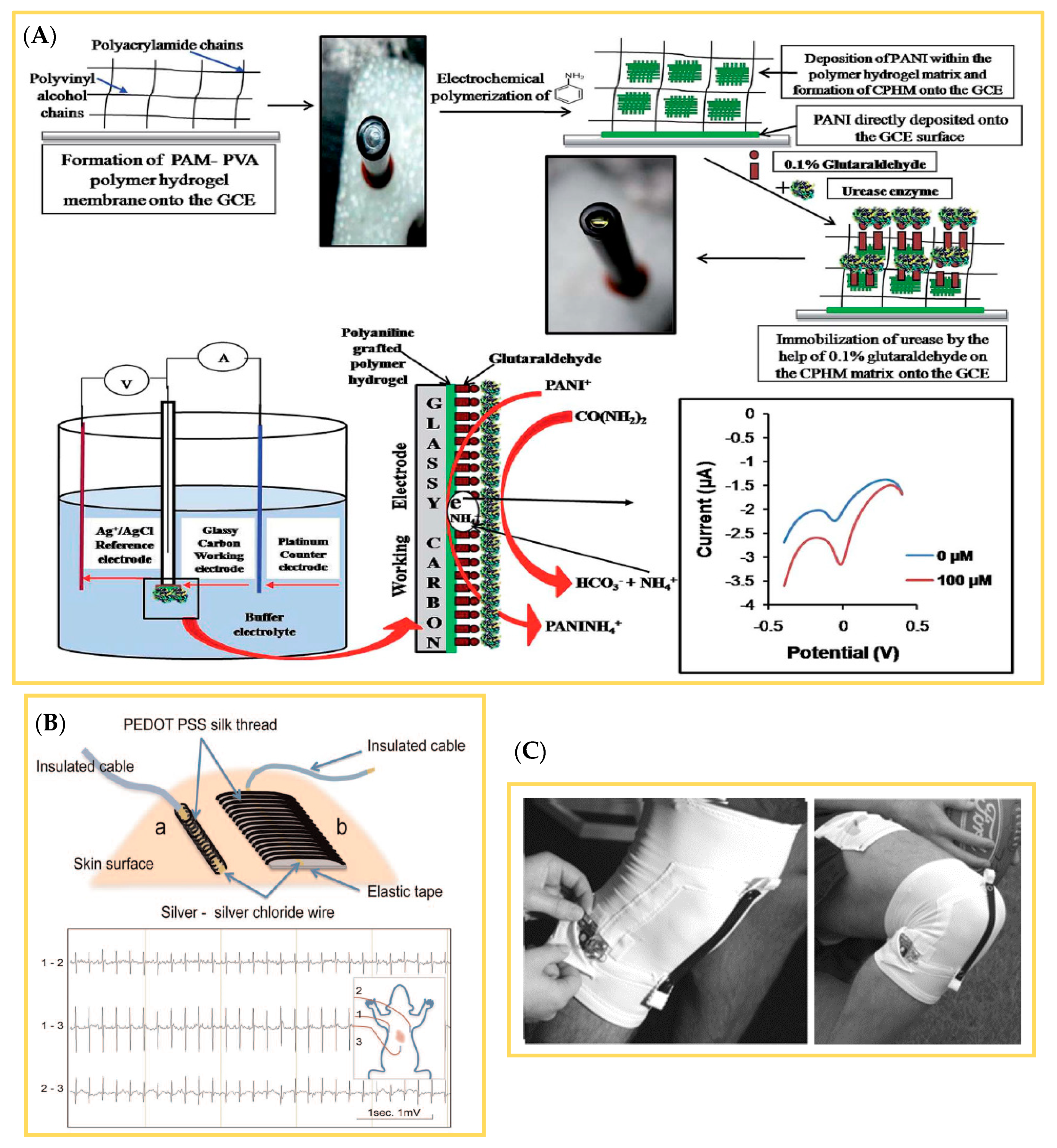
- Trindade, I.G.; Martins, F.; Baptista, P. High electrical conductance poly(3,4-ethylenedioxythiophene) coatings on textile for electrocardiogram monitoring. Synth. Met. 2015, 210, 179–185. [Google Scholar] [CrossRef]
- Najar, S.S.; Kaynak, A.; Foitzik, R.C. Conductive wool yarns by continuous vapour phase polymerization of pyrrole. Synth. Met. 2007, 157, 1–4. [Google Scholar] [CrossRef]
- Hosseini, S.H.; Pairovi, A. Preparation of conducting fibers from cellulose and silk by polypyrrole coating. Iran. Polym. J. 2005, 14, 934–940. [Google Scholar]
- Tsukada, S.; Nakashima, H.; Torimitsu, K. Conductive Polymer Combined Silk Fiber Bundle for Bioelectrical Signal Recording. PLoS ONE 2012, 7, e33689. [Google Scholar] [CrossRef] [Green Version]
- Hirase, R.; Hasegawa, M.; Shirai, M. Conductive fibers based on poly(ethylene terephthalate)-polyaniline composites manufactured by electrochemical polymerization. J. Appl. Polym. Sci. 2002, 87, 1073–1078. [Google Scholar] [CrossRef]
- Varesano, A.; Tonin, C.; Ferrero, F.; Stringhetta, M. Thermal stability and flame resistance of PPy coated PET fibers. J. Thermal Anal. Calorim. 2008, 94, 559–565. [Google Scholar] [CrossRef]
- Xu, Q.; Wei, C.; Fan, L.; Rao, W.; Xu, W.; Liang, H.; Xu, J. Polypyrrole/titania-coated cotton fabrics for flexible supercapacitor electrodes. Appl. Surf. Sci. 2018, 460, 84–91. [Google Scholar] [CrossRef]
- Wu, J.; Zhou, D.; Looney, M.; Waters, P.; Wallace, G.G.; Too, C. A molecular template approach to integration of polyaniline into textiles. Synth. Met. 2009, 159, 1135–1140. [Google Scholar] [CrossRef]
- Grancarici, A.M.; Jerkovici, I.; Dufour, C.; Boussu, F.; Legrand, X.; Koncar, V. Glass/polypropylene Sensor yarns intergration during weaving of 2D structure. In Proceedings of the 8th Central European Conference (CEC 2015) Fiber-Grade Polymers, Chemical Fibers and Special Textiles, University of Zagreb, Faculty of Textile Technology, Zagreb, Crotia, 16–18 September 2015. [Google Scholar]
- Varesano, A.; Ferrer, A.I.; Tonin, C. Electrical performance and stability of polypyrrole coated PET fibres. e-Polymers 2007, 7, 248–261. [Google Scholar] [CrossRef]
- Nardes, A.A.; Kemerink, M.M.; Janssen, R.A.J. Anisotropic hopping conduction in spin-coated PEDOT:PSS thin films. Phys. Rev. B 2007, 76, 085208. [Google Scholar] [CrossRef] [Green Version]
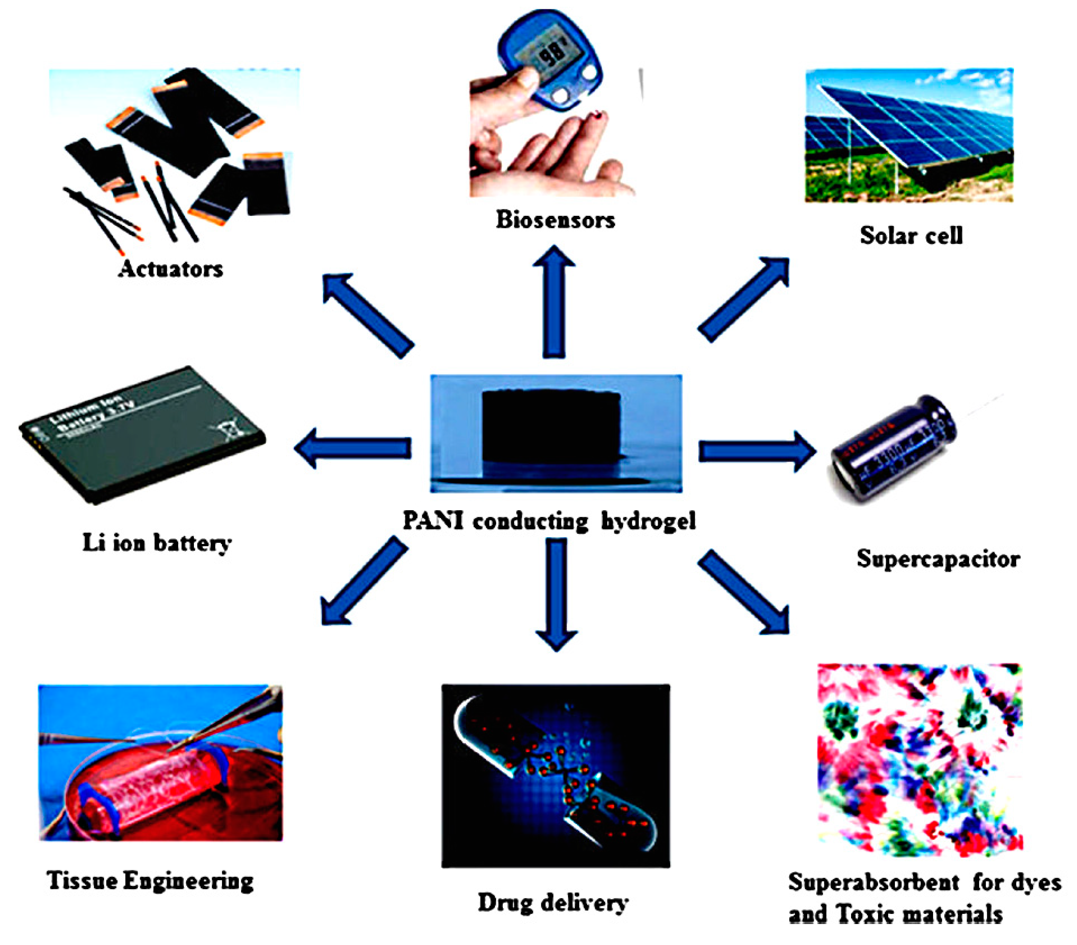
- Pyarasani, R.D.; Jayaramudu, T.; John, A. Polyaniline-based conducting hydrogels. J. Mater. Sci. 2019, 54, 974–996. [Google Scholar] [CrossRef]
- Zhang, Q.; Liu, L.; Pan, C.; Li, D. Review of recent achievements in self-healing conductive materials and their applications. J. Mater. Sci. 2018, 53, 27–46. [Google Scholar] [CrossRef]
- Zhao, C.; Wang, C.; Yue, Z.; Shu, K.; Wallace, G.G. Intrinsically Stretchable Supercapacitors Composed of Polypyrrole Electrodes and Highly Stretchable Gel Electrolyte. ACS Appl. Mater. Interfaces 2013, 5, 9008–9014. [Google Scholar] [CrossRef] [Green Version]
- Tang, Q.; Chen, M.; Yang, C.; Wang, W.; Bao, H.; Wang, G. Enhancing the Energy Density of Asymmetric Stretchable Supercapacitor Based on Wrinkled CNT@MnO2 Cathode and CNT@polypyrrole Anode. ACS Appl. Mater. Interfaces 2015, 7, 15303–15313. [Google Scholar] [CrossRef]
- Fabre, B.; Taillebois, L. Poly(aniline boronic acid)-based conductimetric sensor of dopamine. Chem. Commun. 2003, 9, 2982–2983. [Google Scholar] [CrossRef] [PubMed]
- Yu, H.-H.; Pullen, A.E.; Büschel, M.G.; Swager, T.M. Charge-Specific Interactions in Segmented Conducting Polymers: An Approach to Selective Ionoresistive Responses. Angew. Chem. Int. Ed. 2004, 43, 3700–3703. [Google Scholar] [CrossRef] [PubMed]
- Leopold, S.; Herranen, M.; Carlsson, J.O.; Nyholm, L. In situ pH measurement of the self-oscillating Cu(II)-lactate system using an electropolymerized polyaniline film as a micro pH sensor. J. Electroanal. Chem. 2003, 547, 45–52. [Google Scholar] [CrossRef]
- Matsuguchi, M.; Io, J.; Sugiyama, G.; Sakai, Y. Effect of NH3 gas on the electrical conductivity of polyaniline blend films. Synth. Met. 2002, 128, 15–19. [Google Scholar] [CrossRef]
- Meijerink, M.; Strike, D.; De Rooij, N.; Koudelka-Hep, M. Reproducible fabrication of an array of gas-sensitive chemo-resistors with commercially available polyaniline. Sens. Actuators B Chem. 2000, 68, 331–334. [Google Scholar] [CrossRef]
- Xie, D.; Jiang, Y.; Pan, W.; Li, D.; Wu, Z.; Li, Y. Fabrication and characterization of polyaniline-based gas sensor by ultra-thin film technology. Sens. Actuators B Chem. 2002, 81, 158–164. [Google Scholar] [CrossRef]
- Ogura, K.; Shiigi, H.; Oho, T.; Tonosaki, T. A CO[sub 2] Sensor with Polymer Composites Operating at Ordinary Temperature. J. Electrochem. Soc. 2000, 147, 4351. [Google Scholar] [CrossRef]
- Collins, G.; Buckley, L. Conductive polymer-coated fabrics for chemical sensing. Synth. Met. 1996, 78, 93–101. [Google Scholar] [CrossRef]
- Hosseini, S.H.; Entezami, A.A. Chemical and electrochemical synthesis of homopolymer and copolymers of 3-methoxy-ethoxythiophene with aniline, thiophene and pyrrole for studies of their gas and vapor sensing. Polym. Adv. Technol. 2001, 12, 524–534. [Google Scholar] [CrossRef]
- Sharma, S.; Nirkhe, C.; Pethkar, S.; Athawale, A.A. Chloroform vapour sensor based on copper/polyaniline nanocomposite. Sens. Actuators B Chem. 2002, 85, 131–136. [Google Scholar] [CrossRef]
- Barker, P.; Monkman, A.P.; Petty, M.; Pride, R. A polyaniline/sllicon hybrid field effect transistor humidity sensor. Synth. Met. 1997, 85, 1365–1366. [Google Scholar] [CrossRef]
- Domanský, K.; Baldwin, D.L.; Grate, J.W.; Hall, T.B.; Li, J.; Josowicz, M.; Janata, J. Development and Calibration of Field-Effect Transistor-Based Sensor Array for Measurement of Hydrogen and Ammonia Gas Mixtures in Humid Air. Anal. Chem. 1998, 70, 473–481. [Google Scholar] [CrossRef] [PubMed]
- Kaden, H. Study of the glass/polypyrrole interface in an all-solid-state pH sensor. Solid State Ionics 2004, 169, 129–133. [Google Scholar] [CrossRef]
- Michalska, A.; Maksymiuk, K. Counter-Ion Influence on Polypyrrole Potentiometric pH Sensitivity. Microchim. Acta 2003, 143, 163–175. [Google Scholar] [CrossRef]
- Hosseini, S.H.; Entezami, A.A. Conducting polymer blends of polypyrrole with polyvinyl acetate, polystyrene, and polyvinyl chloride based toxic gas sensors. J. Appl. Polym. Sci. 2003, 90, 49–62. [Google Scholar] [CrossRef]
- Barisci, J.N.; Wallace, G.G.; Andrews, M.K.; Partridge, A.C.; Harris, P.D. Conducting polymer sensors for monitoring aromatic hydrocarbons using an electronic nose. Sens. Actuators B Chem. 2002, 84, 252–257. [Google Scholar] [CrossRef]
- Hamilton, S.; Hepher, M.; Sommerville, J. Polypyrrole materials for detection and discrimination of volatile organic compounds. Sens. Actuators B Chem. 2005, 107, 424–432. [Google Scholar] [CrossRef]
- Deng, Z.; Stone, D.C. Characterization of Polymer Films of Pyrrole Derivatives for Chemical Sensing by Cyclic Voltammetry, X-ray Photoelectron Spectroscopy and Vapour Sorption Studies. Analyst 1997, 122, 1129–1138. [Google Scholar] [CrossRef]
- Zhai, D.; Liu, B.; Shi, Y.; Pan, L.; Wang, Y.; Li, W.; Zhang, R.; Yu, G. Highly Sensitive Glucose Sensor Based on Pt Nanoparticle/Polyaniline Hydrogel Heterostructures. ACS Nano 2013, 7, 3540–3546. [Google Scholar] [CrossRef]
- Zhao, L.; Ma, Z. Facile synthesis of polyaniline-polythionine redox hydrogel: Conductive, antifouling and enzyme-linked material for ultrasensitive label-free amperometric immunosensor toward carcinoma antigen-125. Anal. Chim. Acta 2018, 997, 60–66. [Google Scholar] [CrossRef]
- Das, J.; Sarkar, P. Enzymatic electrochemical biosensor for urea with a polyaniline grafted conducting hydrogel composite modified electrode. RSC Adv. 2016, 6, 92520–92533. [Google Scholar] [CrossRef]
- Pérez-Martínez, C.; Chávez, S.D.M.; Del Castillo-Castro, T.; Ceniceros, T.E.L.; Castillo-Ortega, M.; Rodríguez-Félix, D.; Ruiz, J.C.G. Electroconductive nanocomposite hydrogel for pulsatile drug release. React. Funct. Polym. 2016, 100, 12–17. [Google Scholar] [CrossRef]
- Da Silva, L.B.J.; Oréfice, R. Synthesis and electromechanical actuation of a temperature, pH, and electrically responsive hydrogel. J. Polym. Res. 2014, 21, 1–9. [Google Scholar] [CrossRef]
- Pan, T.; Zuo, X.; Wang, T.; Hu, J.; Chen, Z.; Ren, Y. Electrodeposited conductive polypyrrole/polyaniline composite film for the corrosion protection of copper bipolar plates in proton exchange membrane fuel cells. J. Power Sour. 2016, 302, 180–188. [Google Scholar] [CrossRef]
- Spinks, G.M.; Dominis, A.J.; Wallace, G.G.; Tallman, D.E. Electroactive conducting polymers for corrosion control. J. Solid State Electrochem. 2002, 6, 85–100. [Google Scholar] [CrossRef]
- Truong, V.-T.; Lai, P.; Moore, B.; Muscat, R.; Russo, M. Corrosion protection of magnesium by electroactive polypyrrole/paint coatings. Synth. Met. 2000, 110, 7–15. [Google Scholar] [CrossRef]
- Kim, B.G.; Lim, J.W.; Gil Lee, D. A single-type aluminum/composite hybrid bipolar plate with surface modification for high efficiency PEMFC. Int. J. Hydrog. Energy 2011, 36, 3087–3095. [Google Scholar] [CrossRef]
- Ren, Y.; Anisur, M.; Qiu, W.; He, J.; Al-Saadi, S.; Raman, R.S. Degradation of graphene coated copper in simulated proton exchange membrane fuel cell environment: Electrochemical impedance spectroscopy study. J. Power Sour. 2017, 362, 366–372. [Google Scholar] [CrossRef]


| Electrical Conductivity (S/cm) | |||||||
|---|---|---|---|---|---|---|---|
| Polymer | PAc | PPy | PT | PEDOT | PAni | PPV | PPP |
| Doped | 106–08 | 102–104 | 102 | 102–300 | 102 | 102–10−3 | 102–500 |
| Undoped | 10−2–10−8 | 10−8 | 10−8 | 10−8 | 10−8–10−10 | 10−8–10−13 | 10−8 |
| Material | Method | ICP | Literature |
|---|---|---|---|
| Polyester (PES) | Screen printing | PEDOT:PSS | [23] |
| PU-PA6 | Screen printing | PPy | [24] |
| PES | Screen printing | PEDOT:PSS | [25] |
| PES, PA | Screen printing | PEDOT or PAni | [26] |
| CO | Screen printing | PEDOT:PSS | [27] |
| PET + elastane + PVF | Screen printing | PEDOT:PSS | [28] |
| PA, CO | Inkjet printing | PEDOT:PSS | [29,30] |
| PA | Inkjet printing | PEDOT:PSS | [31,32] |
| ICP | Method | Doping Agent/Oxidant | Conductivity (σ) in S/cm | Reference |
|---|---|---|---|---|
| PAni | Electrospinning | H2SO4 | 0.1 | [46] |
| PAni | Electrospinning | H2SO4 or HCl | 52.9 | [47] |
| PAni nanofibers | Electrospinning | PAni (0.5 wt.%)/PMMA(0.54 wt.%) PAni (0.5 wt.%)//PEO(1 wt.%) PAni (100%) | 10−10 10−6 50 ± 30 | [48] |
| PAni/PEO bicomponent fibers | Electrospinning | PEO 3/4/5w/v% PAni 1.5/2.5/3.5 w/v% | 10−6 to 10−4 | [49] |
| PAni with PSS, PC, PMMA, and PEO | Electrospinning | PAni/PS PAni/PMMA PAni/PC PAni/PEO | 4.1 × 10⁻¹⁴ 4.3 × 10⁻¹⁴ 5.5 × 10⁻¹⁴ 2.4 × 10⁻¹³ | [56] |
| PEDOT/PSS/PEO nanofibers | Electrospinning | PEDOT:PSS | 35.5 | [58] |
| PEDOT/PSS/PVA nanofibers | Electrospinning | PEDOT/PSS/PVA with (0%, 3%, 5%, 8%) of DMSO | 4.8 × 10⁻⁸ 1.7 × 10⁻⁵ | [59] |
| PPy | Electrospinning | PPy-mwCNT | 10−1 | [60] |
| P3HT nanofiber | Electrospinning | Iodine | 122 ± 9 | [63] |
| PEDOT:PSS | Wet spinning | PEDOT:PSS | 10−1 | [65] |
| PEDOT:PSS | Wet spinning | PEDOT:PSS/EG | 195 | [66] |
| PPy | Wet spinning | PPy/DEHS | 3 | [73] |
| PAni with Poly-ω- aminoundecanoic acid | Wet spinning | PAni 5 wt.% PAni 12 wt.% PAni 20 wt.% | 10−5 10−2 10−1 | [74,75] |
| Silk fiber with PAni | Wet spinning | 0.009 wt.% PAni 0.28 wt.% PAni | 6.546 × 10⁴ 0.704 × 10⁴ | [76] |
| PAni/co-PAN | Wet spinning | PAni/PAN/DBSA | 10−3 | [78] |
| PAni/PP | Melt spinning | PAni/PP/DBSA | 10−9 | [82] |
| PAni/PP matrix fibril fiber | Melt spinning | PAni/PP | 10−4 | [83] |
| P3HT fiber | Melt spinning | Doping with FeCl3 | 160 | [84] |
| ICP | Textile Yarns and Fabrics | Coating Technique | Electrical Resistivity or Conductivity | Reference |
|---|---|---|---|---|
| PAni | WO, CO, PA, and PET yarn | Solution polymerization | 23 kΩ/cm/filament | [88] |
| PPy | PA-PU fabric | Solution polymerization | 149 Ω/square | [91] |
| PPy | PA-PU fabric | Currentless coating | - | [92] |
| PAni | PES fabric | In-situ polymerization | - | [93] |
| PT PPy PAni | PET fabric | Knife-over-roll | 3.8 × 10¹² Ω (1.3 wt.%) 2.5 × 10⁸ Ω (5.3 wt.%) 5.9 × 10¹² Ω (6.2 wt.%) | [95] |
| PEDOT:PSS/EG | SE yarn | Dipping and drying | 8.5 S/cm | [96] |
| PPy | CO | Dipping and drying | – | [97] |
| PAni | CO and PET fabric | Dipping and drying | 2.28 × 10⁻⁴ S/cm (CO) 2.15 × 10⁻² S/cm (PET) | [98] |
| PEDOT:PSS/EG | PET and PU fabric | Dipping and drying | - | [103] |
| PPy | WO yarn | Solution polymerization | 50 Ω/cm | [104] |
| PPy | WO, CO, and PA yarn | Vapor polymerization | 0.37–3 kΩ/mm | [105] |
| PEDOT:PSS | E-glass roving | In-situ polymerization | 100 kΩ | [107] |
| PEDOT | PES fiber | Dipping and drying | 600 Ω/cm | [108] |
| PAni | PU yarn | Solution polymerization | 10 | [112] |
| PEDOT:PSS | Viscose (CV) | Chemical vapor polymerization | - | [118] |
| PEDOT:PSS | CV and PET | Chemical vapor deposition | - | [119,120] |
| PEDOT | CO and PET yarn | Vapor polymerization | 10 | [126] |
| PPy | WO yarn | Vapor polymerization | 0.43 kΩ/mm | [129] |
| PPy | CO and SE yarn | Vapor polymerization and solution polymerization | 6.4 × 10⁻⁴ S/cm (CO) and 3.2 × 10⁻⁴ S/cm (SE) | [130] |
| PEDOT:PSS | SE yarn | Dipping and drying | 2 kΩ/mm | [131] |
| PAni | PET yarn | Vapor polymerization | 3 × 10⁵ Ω/square | [132] |
| PPy (FC) PPy (FC + NDC) | PET nonwoven | Dipping and drying | 178.9 Ω (FC) 100.6 Ω (FC + NDC) | [133,137] |
| PPy(TiO2) | CO fabric | In-situ polymerization | - | [134] |
Publisher’s Note: MDPI stays neutral with regard to jurisdictional claims in published maps and institutional affiliations. |
© 2020 by the authors. Licensee MDPI, Basel, Switzerland. This article is an open access article distributed under the terms and conditions of the Creative Commons Attribution (CC BY) license (http://creativecommons.org/licenses/by/4.0/).
Share and Cite
Onggar, T.; Kruppke, I.; Cherif, C. Techniques and Processes for the Realization of Electrically Conducting Textile Materials from Intrinsically Conducting Polymers and Their Application Potential. Polymers 2020, 12, 2867. https://doi.org/10.3390/polym12122867
Onggar T, Kruppke I, Cherif C. Techniques and Processes for the Realization of Electrically Conducting Textile Materials from Intrinsically Conducting Polymers and Their Application Potential. Polymers. 2020; 12(12):2867. https://doi.org/10.3390/polym12122867
Chicago/Turabian StyleOnggar, Toty, Iris Kruppke, and Chokri Cherif. 2020. "Techniques and Processes for the Realization of Electrically Conducting Textile Materials from Intrinsically Conducting Polymers and Their Application Potential" Polymers 12, no. 12: 2867. https://doi.org/10.3390/polym12122867
APA StyleOnggar, T., Kruppke, I., & Cherif, C. (2020). Techniques and Processes for the Realization of Electrically Conducting Textile Materials from Intrinsically Conducting Polymers and Their Application Potential. Polymers, 12(12), 2867. https://doi.org/10.3390/polym12122867