Abstract
As the world faces water shortage and pollution crises, the development of novel visible light photocatalysts to purify water resources is urgently needed. Over the past decades, most of the reported photocatalysts have been in powder or granular forms, creating separation and recycling difficulties. To overcome these challenges, a flexible and recyclable heterostructured TiO2/polyvinylidene fluoride/graphitic carbon nitride (TiO2/PVDF/g-C3N4) composite was developed by combining electrospinning, sintering and hydrothermal methods. In the composite, PVDF was used as a support template for removing and separating the photocatalyst from solution. Compared with pure TiO2, the TiO2/PVDF/g-C3N4 composite exhibited the extended light capture range of TiO2 into the visible light region. The photogenerated carriers were efficiently transferred and separated at the contact interface between TiO2 and g-C3N4 under visible light irradiation, which consequently increased the photocatalytic activity of the photocatalyst. In addition, the flexible composites exhibited excellent self-cleaning properties, and the dye on the photocatalysts was completely degraded by the as-prepared materials. Based on the intrinsic low cost, recyclability, absorption of visible light, facile synthesis, self-cleaning properties and good photocatalytic performances of the composite, the photocatalyst is expected to be used for water treatment.
1. Introduction
In recent decades, photocatalysis has been recognized as the most promising and green technologies due to its environmentally friendly, low-cost and high efficiency characteristics. It has been widely used in the fields of environmental management and energy conversion [1,2]. The key of photocatalytic technology is to prepare advanced photocatalysts that can make full use of solar light sources to meet the urgent needs of current environmental treatment. The effective materials commonly used in recent years mainly include semiconductor photocatalysts, such as, metal and non-metal oxides, sulfides and nitrides [3,4]. Among these materials, the good photocatalytic performance and stability of titanium oxide (TiO2) have been largely demonstrated. As one of the most outstanding transition metal oxide semiconductor photocatalyst, TiO2 exhibits of stable physical-chemical properties, low toxicity and excellent optical performances. Furthermore, it is easily synthesized, and it has a low cost [5,6,7]. However, TiO2 is limited in the practical applications, because it has a large band gap energy (3.2 eV) as an n-type wide band gap semiconductor and fast recombination rate of photogenerated electron-hole pairs [8]. These defects lead to low utilization of sunlight and reduce the quantum efficiency, thereby indirectly affecting the photocatalytic performance [9,10]. In addition, TiO2 that exists in a powder or particle state is difficult hard to separate from the solution; and even causes secondary pollution to the environment [11,12]. Therefore, it is necessary to find an efficient strategy to simultaneously expand the sunlight capture range and the narrow band gap of TiO2, enhance the lifetime of photogenerated electron-hole pairs and facilitate recycling. To date, various methods have been developed, and the design of heterostructured photocatalysts is an effective option [13,14,15]. First, the TiO2 compound with a narrow band gap semiconductor can capture the light in the visible region [16]. Second, the matching energy level coupling between the narrow band gap semiconductor and the wide band gap TiO2 can promote the transfer and separation of photogenerated carriers, thereby prolonging the lifetime of the photogenerated electron-hole pairs and improving the photocatalytic activity of the photocatalyst [17].
As a narrow band gap semiconductor (2.7 eV), g-C3N4 exhibits stable physicochemical properties, thermal stability and remarkable optoelectronic transmission performances. Furthermore, it is non-toxic it is easily stored, and it can be obtained from a wide variety of sources [18]. It has been proven in recent years to be an optimal choice for composing heterostructured materials with wide band gap semiconductors. For example, Wang et al. developed a novel in situ microwave-assisted synthesis approach for fabricating N-TiO2/g-C3N4 composites, and the products exhibited remarkable enhancements of their photocatalytic activities [19]. Miranda et al. obtained the g-C3N4/TiO2 composites, which were highly photoactive by combining hydrothermal and sintering methods, and the final conversion rate of phenol was around 90% [20]. Han et al. prepared a g-C3N4/TiO2 composite by integrating electrospinning and calcination technology, and the hydrogen production rate under sunlight was 8931.3 μmol·h−1·g−1 [21]. However, these prepared materials were still in powder form. Therefore, they were difficult to recycle after the photocatalytic process [22,23]. This caused not only significant waste of the photocatalyst, but also secondary pollution to the environment. At present, a number of methods for recovering inorganic photocatalyst materials have been reported, such as adding magnetic materials, making tough, recyclable and flexible thin film materials, and loading them on organic polymer materials [24,25,26,27,28,29]. Usually, polyvinylidene fluoride (PVDF) is selected as the support material by electrospinning due to its mechanical strength stability, heat resistance and ease of forming fibers [30,31,32]. Our previous work also indicated that the polymer fibers of PVDF prepared by electrospinning could be used as the substrate with inorganic TiO2 tightly embedded on the fibers [33].
In this work, flexible TiO2/PVDF/g-C3N4 composites were prepared through electrospinning, sintering and a hydrothermal treatment [34,35]. The hydrothermal method not only successfully coated the PVDF fibers with g-C3N4, but also in situ formed granular TiO2 on the PVDF fibers. The photocatalytic mechanism of the composite during the degradation of pollutants under light has been reasonably explained. The results confirmed that the TiO2/PVDF/g-C3N4 composite extended the response of TiO2 to the visible light range and simultaneously significantly improved the photocatalytic activity. In addition, the as-prepared material with the support of PVDF could be recycled easily and contamination by pollutants could be prevented. Therefore, the flexible TiO2/PVDF/g-C3N4 composite is a good candidate for use in the environmental treatment of organic pollutants.
2. Experimental
2.1. Materials
PVDF (MW = 500,000) powder was purchased from Shanghai 3F New Materials Co., Ltd. Melamine (Shanghai, China) (CP, 98.0%) was purchased from Sigma-Aldrich (Shanghai, China). Tetrabutyl orthotitanate (TBOT, CP, 98.0%), rhodamine B (RhB), methyl blue (MB), methyl orange (MO), dimethylformamide (DMF, AR, 99.5%), sulphuric acid (H2SO4, CP, 95.0%–98.0%) and acetone (CP, 99.0%) were obtained from SinopharmChemical Reagent Co., Ltd (Shanghai, China). Degussa P25 (P25®) was purchased from Evonik Degussa Company (Shanghai, China). All chemical reagents were used as received without further purification.
2.2. Preparation of TBOT/PVDF Fibers
First 4 g of PVDF powder, 10 mL of DMF and 12 mL of acetone were placed into a 50 mL conical flask and stirred vigorously for 1 h. Next 10 mL of TBOT was added to the solution and stirred continuously for 1 h. The TBOT/PVDF solution was ultrasonically treated for 30 min, and the resultant solution was an electrospinning precursor. TBOT/PVDF fibers were obtained by electrospinning. During the electrospinning process, DC high voltage power was supplied at 10 kV, the pump rate was 2 mL h−1, and the tip-to-collector distance was 10 cm. Finally, the collected TBOT/PVDF fibers were dried at 60 °C.
2.3. Preparation of g-C3N4
The g-C3N4 was prepared following a previously reported calcination method [36]. Typically, 3 g of melamine was uniformly placed in a lidded crucible, after which it was transferred to a muffle furnace and maintained at 550 °C for 4 h to produce the g-C3N4. The obtained g-C3N4 was then ground in a mortar for 0.5 h to obtain a yellow powder.
2.4. Fabrication of Flexible TiO2/PVDF/g-C3N4 Composite
The prepared TBOT/PVDF fibers were cut into squares with sizes of 2.5 cm × 2.5 cm. Different amounts of g-C3N4 powder were added into 30 mL of a 0.5 M sulfuric acid water solution and were well stirred for 60 min. The mixture solution was then transferred into a 50 mL polytetrafluoroethylene (PTFE) autoclave containing a TBOT/PVDF square, and underwent hydrothermal treatment at 150 °C for 24 h (as shown in Table 1). The resulting sample was washed with deionized water and anhydrous ethanol for several times. After drying at 60 °C for 10 h, the final product TiO2/PVDF/g-C3N4 (TPCN) was obtained. As a control experiment, TiO2/PVDF fibers were also prepared under similar conditions without the addition of g-C3N4.

Table 1.
TiO2/PVDF/g-C3N4 (TPCN) samples.
2.5. Synthesis and Application Process
As shown in Figure 1, TPCN were synthesized by combining the facile electrospinning method, sintering and a controllable hydrothermal process [31]. First, TBOT/PVDF fibers were obtained using convenient and simple electrospinning technology [28,33]. Secondly, g-C3N4 was collected by one-step sintering [36]. Later, the cut TBOT/PVDF (2.5 cm × 2.5 cm) and a certain amount of g-C3N4 were placed into a 50 mL reactor for hydrothermal treatment to prepare flexible TPCN. The photocatalyst contaminated with the dyes was subjected to a period of light irradiation to study the photocatalytic performance. Finally, collecting and cleaning the flexible TPCN composite was collected and cleaned from the solution for next reuse.

Figure 1.
Schematic illustration of synthesis and photocatalytic application of the TPCN composites.
2.6. Characterization
X-ray diffraction (XRD) patterns were collected using a Rigaku SmartLab X-ray diffractometer with Cu-Kα radiation (λ = 1.54178 Å) in the sweep range from 5° to 85° at a scan rate of 5° min−1. The morphology and structure images of the samples were obtained using scanning electron microscopy (SEM, JEOL JSM-7800F, JEOL, Tokyo, Japan). X-ray photoelectron spectroscopy (XPS) was performed using by a Thermo Scientific Escalab 250Xi instrument (Thermo Fisher Scientific, Shanghai, China) with an Al Kα X-ray source at room temperature. The photoluminescence (PL) spectrum was obtained using a Hitachi F-4600 fluorescence spectrometer (HITACHI, Tokyo, Japan) to character the recombination behaviors of the photogenerated carriers using an excitation wavelength of 320 nm. The UV-Vis diffuse reflectance spectra (DRS) of the prepared samples were measured using a PERSEE-T9 UV/Vis spectrophotometer with a scanning wavelength range of 200–800 nm with a resolution of 0.2 nm.
2.7. Photocatalytic Activity Performance
The photocatalytic activities of the as-prepared samples were evaluated based on the degradation of RhB, a representative water pollutant, under visible light irradiation with an 800 W Xe lamp (equipped with a 420 nm cut-off filter, Beijing Princes Technology Co., Ltd., Beijing, China). The different types of prepared photocatalysts were added into 100 mL quartz tubes containing 50 mL of homogeneous RhB aqueous solution (5 mg L−1). The quartz tube was then kept in a dark atmosphere for 30 min while stirring continuously to ensure the photocatalyst surfaces achieved adsorption–desorption equilibrium [37,38]. A Xe lamp was subsequently turned on during the photodegradation process. Circulating water was applied in the reaction system to maintain a constant temperature at 20 °C. Three-milliliter samples of the suspension were removed for centrifugation at specified time intervals. To determine the concentrations of the degraded pollutants, the absorption spectra of RhB in solution after centrifugation were detected using a PERSEE-T9 UV/VIS spectrophotometer (Shanghai Yuan Analysis Instrument Co., Ltd., Shanghai, China). To confirm the recycling stability, the as-prepared composite was washed several times with deionized water followed by drying at 60 °C for 10 h.
3. Results and Discussion
3.1. Structure and Morphological Characteristics
The XRD patterns of the as-prepared photocatalysts are depicted in Figure 2. As shown in Figure 2, curve a, only one broad diffraction peak located at 20.4° was detected, which was attributed to the pure β phase of PVDF [39]. This showed that during the electrospinning process, the TBOT did not convert to TiO2 with good crystallinity, and only PVDF and the precursors of TiO2 were presented in the form of fibers. After undergoing the hydrothermal process, the TBOT began to transform into anatase phase TiO2, due to the reactions of the fibers in the 0.5 M H2SO4 at 150 °C for 24 h, as shown in Figure 2, curve b. The curve contains three sharp 2θ peaks at 25.4°, 48.0° and 54.8°, which were attributed to the (101), (200) and (211) crystal faces of the anatase TiO2 (JCPDS 21-1272), respectively [40]. No other diffraction peaks were detected, except for those of the PVDF and anatase TiO2. Figure 2, curve f contains one broad diffraction peak at 13.1° and one narrow diffraction peak at 27.5°, which corresponded to the (001) and (002) crystal faces of the g-C3N4 (JCPDS 87-1526) [41]. In Figure 2, curves c and d, the peaks of TPCN1, TPCN2 and TPCN3 were similar to those of curve b. The peak intensities of PVDF and anatase TiO2 began to decrease as the content of g-C3N4 used in the hydrothermal process increased, indicating that the content of g-C3N4 grown on the fibers gradually increased and the surface quantities of PVDF and anatase TiO2 were masked. Thus, it was concluded that the g-C3N4 had bonded to the PVDF/TiO2 fibers, and the TPCN composites were successfully synthesized using the electrospinning technology and hydrothermal process.
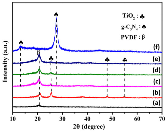
Figure 2.
XRD patterns of (a) TBOT/PVDF fibers, (b) TiO2/PVDF fibers, (c) TPCN1, (d) TPCN2 (e) TPCN3 and (f) g-C3N4.
The typical SEM images were used to observe the microscopic features and structures of the as-prepared materials. The initial electrospun TBOT/PVDF fibers were disordered, heterogeneous and interlaced to form a nonwoven material, as shown in Figure 3a. Partial fiber fractures fracture occurred, which mainly occurred because the TBOT in the fibers hydrolyzed due to contact with moisture in the air. Figure 3b reveals that the surface roughness of the TiO2/PVDF fibers appeared to be different from the surface roughness of the TBOT/PVDF fibers. Thus, the precursor of TiO2 was confirmed to have been successfully doped into the fibers. After the initial product underwent hydrothermal treatment, unevenly distributed particulate matter could be clearly observed on the surfaces of the fibers, which was determined by the XRD patterns to be anatase phase TiO2. In the process of acidic hydrothermal growth, the TBOT doped inside and outside the fibers was simultaneously hydrolyzed to TiO2. Figure 3c depicts the morphology of the g-C3N4 prepared using a previously reported method, which possessed a layered structure [42]. As shown in Figure 3d, the fibers were embedded in the g-C3N4, and the g-C3N4 was tightly wrapped around the fibers. The XRD patterns in Figure 2 also demonstrated that the TiO2 and g-C3N4 could grow simultaneously on the PVDF fibers by addition of g-C3N4 in the hydrothermal solution.
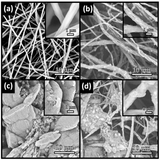
Figure 3.
SEM images of (a) TBOT/PVDF fibers, (b) TiO2/PVDF fibers, (c) g-C3N4 and (d) TPCN2.
The XPS spectra were obtained to determine the surface elemental compositions, chemical bonding states and formation of TiO2/g-C3N4 heterostructures in the photocatalysts. High-resolution elemental analysis was performed to characterize the characteristic peaks of F, C, N, Ti and O. The F 1s spectrum in Figure S1 (from Supplementary Materials) shows one major peak centered at 688.2 eV, which was attributed to the presence of the most abundant component, PVDF, in the fibers. [33] In Figure 4a, four carbon species were found in the binding energy region of C 1s spectrum, including 286.5 eV (C–N) and 290.9 eV (F–C–F) [43,44,45]. Meanwhile, the strong peak of N 1s shown in Figure 4b observed at 400.5 eV was related to the sp2 hybridized nitrogen (C=N–C) [46]. The results confirmed that the g-C3N4 was successfully compounded with the fibers. In the Ti 2p profiles (Figure 4c), the spectrum was divided into two peaks centered at 459.4eV and 465.2 eV, corresponding to Ti 2p3/2 and Ti 2p1/2, respectively, due to the Ti4+ of TiO2. [47] As displayed in Figure 4d, the O1s peaks at binding energies of 530.7 eV and 532eV were associated with the Ti–O, containing O2−, in the TiO2 and oxygen in the surface –OH groups, respectively, proving that the TBOT had completely converted to TiO2 in the hydrothermal process [48]. Thus, the result was well matched with the results obtained by SEM and XRD.
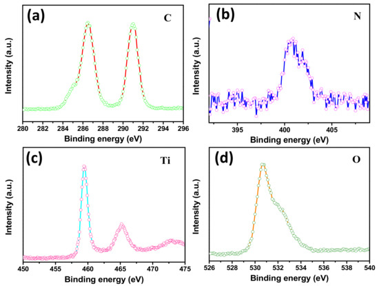
Figure 4.
HR-XPS spectra of TPCN2 composite synthesized at 150 °C for 24 h: (a) C 1s (b) N 1s, (c) Ti 2p and (d) O 1s.
3.2. Optical Characteristics
The PL spectra were used to determine the recombination efficiencies of the photogenerated carriers and characterize the electron hole pair transfer behavior at the contact interface. The PL spectra of the TiO2/PVDF fibers and TiO2/PVDF fibers with different contents of g-C3N4 are shown in Figure 5. The TiO2/PVDF and P25® both produced four main emission peaks. The emission peak approximately 406 nm was due to the TiO2/PVDF, while the peak located at approximately 402 nm was due to the P25®. The position of these two peaks may have been caused by the near-band edge emission of TiO2 and P25® [49,50]. In the various as-prepared TPCN composites, the emission peaks for TiO2/PVDF and P25® were all transferred to a position of 437 nm, which was caused by the combination of g-C3N4. As the content of g-C3N4 used in the reaction solution increased, the intensity of the emission peaks for different TPCN contents increased, because g-C3N4 has a strong recombination rate of photogenerated carriers as previously reported [42]. In addition, five emission peaks still appeared for the TiO2/PVDF and P25® between 439 and 495 nm, which were assigned to the oxygen vacancy related defects occurring in the preparation process [51,52].
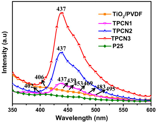
Figure 5.
Photoluminescence (PL) spectra of TiO2/PVDF, P25® and various as-prepared TPCN composites.
The UV-Vis absorption spectra in Figure 6 were used to confirm the optical absorption properties of the TiO2/PVDF, TPCN1, TPCN2 and TPCN3, which were obtained by converting the UV-Vis diffuse reflectance spectra using the Kubelka−Munk function [53,54]. The curves of the TiO2/PVDF suddenly and abruptly decreased at around 400 nm, indicating that there was no response in the visible range, and the response was in the ultraviolet range, owing to the formation of TiO2 on the fibers. After adding various contents ofg-C3N4, the curves exhibited enhanced responses between 400 and 750 nm. The reason for the decrease in absorption in the UV region was that the addition of g-C3N4 obstructed the ultraviolet absorption of some of the TiO2, increasing the absorption in the visible region. Thus, the curves proved that the range of light captured by the photocatalysts extended to the visible light region because the g-C3N4 was bonded to the TiO2/PVDF fibers during the hydrothermal process. We make the tangent intersect the abscissa axis and show the absorbance of various components. As the content of g-C3N4 added during the hydrothermal process increased, the response of the TiO2/PVDF/g-C3N4 in the visible light region gradually increased. By extrapolating the Kubelka−Munk function, the band gap energy of the as-prepared products was estimated to be 2.6–3.15 eV. As shown in Figure 6, the curves of TPCN1, TPCN2 and TPCN3 exhibited a blue shift in the band gap energy compared to the TiO2/PVDF and began to respond to the visible light region.
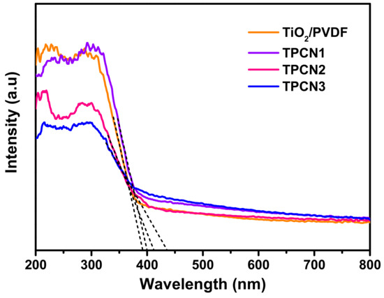
Figure 6.
UV-Vis absorption spectra of TiO2/PVDF and various as-prepared TPCN composites.
3.3. Photocatalytic and Self-Cleaning Performances
By detecting the change of the RhB concentration under visible light irradiation for a period of time, the photocatalytic performances of the as-prepared composites were evaluated. The sample was treated in a dark environment for 30 min to achieve adsorption equilibrium. Figure 7a shows the RhB degradation curves of the as-prepared photocatalysts under the same conditions, including P25®, TiO2/PVDF, g-C3N4, TPCN1, TPCN2 and TPCN3. RhB without an added photocatalyst was used as a blank control group to confirm the inherent stability of the solution under visible light irradiation. As expected, a negligible change in the concentration of RhB occurred. The curves showed that TPCN2 exhibited a higher photocatalytic performance for degrading RhB than other types of photocatalysts. In particular, the photocatalytic activities of various TPCN composites were higher than those of the g-C3N4 and TiO2/PVDF fibers, which indicated that the amount of g-C3N4 coupled with TiO2/PVDF fibers significantly affected the photocatalytic activity during the reaction process. The effective separation of electron and holes pairs and the expanded specific surface area affected the interfacial contact of the g-C3N4 and TiO2 in the composite system. The proper amount of g-C3N4 added to the composite can significantly affected the efficiency of the photocatalysis. The photocatalytic process for the degradation of RhB can also be expressed using pseudo-first-order kinetics, as follows: [55]
where kapp is the reaction rate constant, and C0 and C are the concentrations of RhB initially and time t, respectively. The pseudo-first-order kinetics curves and reaction rate constant of different photocatalysts are shown in Figure 7b and Figure S3. The calculated reaction rate constant of TPCN2 was 0.0083, which were approximately 2.95, 2.41, 2.84, 1.9 and 1.56 times higher than those of TiO2/PVDF, P25®, g-C3N4, TPCN1 and TPCN3, respectively. The results indicated that the as-prepared product was suitable as a photocatalyst for eliminating actual environmental pollution. Furthermore, photocatalytic recyclability is an important attribute for engineering applications. Over three successive cycles, Figure 7c shows that the degradation rate of TPCN2 decreased by less than 5%, and similar photocatalytic behavior was maintained.
–ln(C/C0) = kappt

Figure 7.
(a) Curves of photocatalytic degradation RhB (10 mg/L 50 mL 20 °C) over different samples: RhB bared, P25®, TiO2/PVDF and as-prepared TPCN composites. (b) Kinetic linear fitting curves for photocatalytic degradation of RhB by different photocatalysts. (c) The durability of TPCN2 for dye removal after several cycles.
In Figure 8a–h, the flexible bending performance of the as-prepared sample was demonstrated. By bending at different angles, the fiber membrane still could well been restored. The flexible nature of the sample contributed to the recycling. Under the irradiation of UV light with a wavelength of 254 nm, the self-cleaning properties of the photocatalyst contaminated with MB were measured as shown in Figure 8i,j. Obviously, the color of the photocatalyst contaminated with the dye having a concentration of 10 mg L−1 was barely visible when exposed to UV light for 1 h. Similarly, the dye prior polluted by 10 mg L−1 RhB was completely removed in Figure 8k,l after irradiation to UV light for 1 h. Veziroglu et al. studied that the residual residue on the CeO2-TiO2 hybrid structure during oleic acid treatment completely disappeared within 60 min under ultraviolet irradiation [56]; Zhang et al. reported the self-cleaning performance of CuS/PVDF/TiO2 was studied by dropping 10 mg L−1 of RhB, methyl orange, and methylene blue onto the surface of the composite under visible light. The color of these dyes almost disappeared in about 120 min [57]. As we know, in the photocatalysis process, the photocatalysts are easily attached to dye molecules causing self-pollution, which reduces its photocatalytic performance. The as-prepared products can greatly improve the photocatalytic effect in practical use due to their self-cleaning ability.
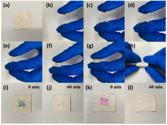
Figure 8.
Photographs: flexible performance of TPCN2 (a–h), stained with MB (i,j) and RhB (k,l) under UV light irradiation, respectively.
3.4. Reaction Mechanisms
To further study the possible reaction mechanism of the prepared photocatalyst, a series of comparative experiments of radical scavengers were carried out in the reaction system to determine the active material leading to the photocatalytic process. The scavengers N2, EDTA-2Na, AgNO3 and TBA were added to the removal of the active substances , h, to further study the possible reaction and OH, respectively. As shown in Figure 9a, the photocatalytic properties changed slightly after the addition of EDTA-2Na, AgNO3 and TBA, which means that h, e− and played minor roles in the degradation of RhB. When N2 was added to the solution, the degradation efficiency of the CNT2 for RhB decreased sharply, indicating that ∙ played a leading role in the photocatalytic degradation of the pollutants. Based on the above results, a photocatalytic mechanism of the CNT degradation of the pollutants under visible light irradiation was proposed. The mechanism of photogenerated carrier transfer and separation under visible light irradiation is shown in Figure 9b. When the light irradiated the sample, an electron (e−) was excited from the valence band (VB) of g-C3N4 to the conduction band (CB), leaving equal numbers of holes (h+) in the VB. Therefore, the separation of photogenerated carriers inherent in the material was realized. Meanwhile, an electron (e−) of TiO2 was excited from the VB to the CB, leaving the same number of holes (h+) into VB. Since the VB potential of TiO2 was lower than that of g-C3N4, the electrons were rapidly transferred from the CB of g-C3N4 to the CB of TiO2 through the tightly contact interface. Thus, the holes moved from the VB of TiO2 to the VB of g-C3N4. Eventually, the survival time of the photogenerated carriers was prolonged, which was beneficial to the enhancement of the photocatalytic activity. The electrons transferred to the CB of TiO2 were trapped by oxygen molecules in the dye solution, and thus a strong oxidizing oxygen radical (∙) formed on the surface of the sample () [58]. Meanwhile, hydroxyl radicals () were also produced on the surface of the photocatalyst due to the holes of the VB transferred to the g-C3N4 reacting with water molecules in solution, () [59]. The ∙ and attached to the sample surface had strong oxidizing properties. In the process of contacting with organic pollutant RhB, the RhB finally mineralized into H2O and CO2 after undergoing the processes of N-demethylation, chromophore cleavage, ring-opening and mineralization [60].
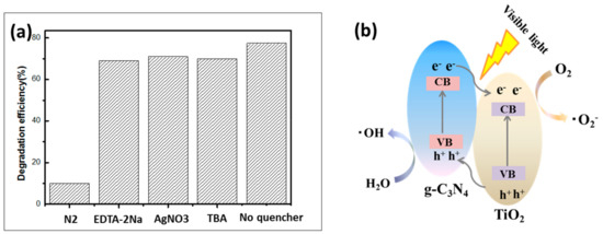
Figure 9.
(a) Explore the effects of photocatalytic efficiency by adding different types of scavengers. (b) Schematic diagrams photocatalytic mechanism of the as-prepared TPCN composite under the visible light irradiation.
4. Conclusions
Heterostructured as-prepared TPCN composites with excellent flexibilities and outstanding visible light photocatalyzed performances and self-cleaning characteristics were developed by combining a facile electrospinning method with a convenient hydrothermal process. The TBOT that unevenly distributed on the surface and inside the fibers converted into granular TiO2 during the hydrothermal process, which was tightly embedded on the PVDF fibers. The introduction of the narrow band gap g-C3N4 in composed the novel TiO2/g-C3N4 heterostructures, ensured that the TPCN composite possessed a lower recombination efficiency of photogenerated carriers and remarkable photocatalytic activity under visible light irradiation. Use of the organic PVDF fibers as the support substrate enabled the composite to achieve self-standing and bendable properties. In contrast to the conventional powder photocatalysts, the TPCN composite could be easily recovered, so the secondary pollution challenge could be overcome. The current work offers a novel synthesis strategy for developing a new-type of recyclable photocatalyst with a visible light response, good photocatalytic performance and self-cleaning characteristics.
Supplementary Materials
The following are available online at https://www.mdpi.com/2073-4360/12/1/55/s1.
Author Contributions
Formal analysis, T.-T.Z. and X.-X.W.; Funding acquisition, L.-X.C. and Y.-Z.L.; Investigation, T.-T.Z., F.-H.Z. and Y.-Q.C.; Methodology, T.-T.Z. and J.-S.Y.; Writing—original draft, T.-T.Z. All authors have read and agreed to the published version of the manuscript.
Funding
This work was supported by the National Natural Science Foundation of China (51673103 and 51973100), and the Taishan Scholars Program.
Conflicts of Interest
The authors declare no conflicts of interest.
References
- Harish, K.N.; Naik, H.S.B.; Kumar, P.N.P.; Viswanath, R. Optical and photocatalytic properties of solar light active Nd-substituted Ni ferrite catalysts: for environmental protection. ACS Sustain. Chem. Eng. 2013, 1, 1143–1153. [Google Scholar] [CrossRef]
- Chen, J.; Poon, C.S. Photocatalytic cementitious materials: influence of the microstructure of cement paste on photocatalytic pollution degradation. Build. Environ. 2009, 43, 8948–8952. [Google Scholar] [CrossRef]
- Nosaka, Y.; Norimatsu, K.; Miyama, H. Immobilization of enzyme on nylon containing pendant quaternized amine groups. Chem. Phys. Lett. 1984, 27, 1390–1392. [Google Scholar]
- Marschall, R.; Wang, L. Non-metal doping of transition metal oxides for visible-light photocatalysis. Catal. Today 2014, 225, 111–135. [Google Scholar] [CrossRef]
- Shi, X.; Ueno, K.; Takabayashi, N.; Misawa, H. Improvement of Plasmon-Enhanced Photocurrent Generation by Interference of TiO2 Thin Film. J. Phys. Chem. C 2013, 117, 24733–24739. [Google Scholar] [CrossRef]
- Khan, M.; Gul, S.R.; Li, J.; Cao, W. Variations in the structural, electronic and optical properties of N-doped TiO2 with increasing N doping concentration. Mod. Phys. Lett. B 2015, 29, 1550022. [Google Scholar] [CrossRef]
- Pakdel, E.; Daoud, W.A.; Seyedin, S.; Wang, J.; Razal, J.M.; Sun, L.; Wang, X.G. Tunable photocatalytic selectivity of TiO2/SiO2 nanocomposites: Effect of silica and isolation approach. Colloids Surf. A 2018, 552, 130–141. [Google Scholar] [CrossRef]
- Li, X.Z.; Li, F.B. Study of Au/Au3+-TiO2 photocatalysts toward visible photooxidation for water and wastewater treatment. Environ. Sci. Technol. 2001, 35, 2381–2387. [Google Scholar] [CrossRef] [PubMed]
- Zalfani, M.; Schueren, B.V.D.; Mahdouani, M.; Bourguiga, R.; Yu, W.B.; Wu, M.; Deparis, O.; Li, Y.; Su, B.L. ZnO quantum dots decorated 3DOM TiO2 nanocomposites: Symbiose of quantum size effects and photonic structure for highly enhanced photocatalytic degradation of organic pollutants. Appl. Catal. B Environ. 2016, 199, 187–198. [Google Scholar] [CrossRef]
- Jiao, J.; Wei, Y.; Zhao, Y.; Zhao, Z.; Duan, A.; Liu, J.; Pang, Y.; Li, J.; Jiang, G.; Wang, Y. AuPd/3DOM-TiO2 catalysts for photocatalytic reduction of CO2: High efficient separation of photogenerated charge carriers. Appl. Catal. B Environ. 2017, 209, 228–239. [Google Scholar] [CrossRef]
- Georgakopoulos, T.; Apostolopoulou, A.; Todorova, N.; Pomoni, K.; Trapalis, C.; Stathatos, E. Evaluation of photoconductive and photoelectrochemical properties of mesoporous nanocrystalline TiO2 powders and films prepared in acidic and alkaline media. J. Alloys Compd. 2017, 692, 313–321. [Google Scholar] [CrossRef]
- Solís-Casados, D.A.; Escobar-Alarcón, L.; Gómez-Oliván, L.M.; Poniatowski, E.H.; Klimova, T. Photodegradation of pharmaceutical drugs using Sn-modified TiO2 powders under visible light irradiation. Fuel 2017, 198, 3–10. [Google Scholar] [CrossRef]
- Liang, J.; Wang, C.; Zhao, P.; Wang, Y.; Ma, L.; Zhu, G.; Hu, Y.; Lu, Z.; Xu, Z.; Ma, Y. Interface engineering of anchored ultrathin TiO2/MoS2 heterolayers for highly-efficient electrochemical hydrogen production. ACS Appl. Mater. Interfaces 2018, 10, 6084–6089. [Google Scholar] [PubMed]
- Zhang, J.; Zhang, L.; Shi, Y.; Xu, G.; Zhang, E.; Wang, H.; Kong, Z.; Xi, J.; Ji, Z. Anatase TiO2 nanosheets with coexposed {101} and {001} facets coupled with ultrathin SnS2 nanosheets as a face-to-face n-p-n dual heterojunction photocatalyst for enhancing photocatalytic activity. Appl. Surf. Sci. 2017, 420, 839–848. [Google Scholar] [CrossRef]
- Lu, Z.; Zeng, L.; Song, W.; Qin, Z.; Zeng, D.; Xie, C. In situ synthesis of C-TiO2/g-C3N4 heterojunction nanocomposite as highly visible light active photocatalyst originated from effective interfacial charge transfer. Appl. Catal. B Environ. 2017, 202, 489–499. [Google Scholar] [CrossRef]
- Zhang, X.; Huang, H.; Liu, J.; Liu, Y.; Kang, Z. Carbon quantum dots serving as spectral converters through broadband upconversion of near-infrared photons for photoelectrochemical hydrogen generation. J. Mater. Chem. A 2013, 1, 11529–11533. [Google Scholar] [CrossRef]
- Zhou, W.; Sun, F.; Pan, K.; Tian, G.; Jiang, B.; Ren, Z.; Tian, C.; Fu, H. Well-Ordered Large-pore mesoporous anatase TiO2 with remarkably high thermal stability and improved crystallinity: Preparation, characterization, and photo. Adv. Funct. Mater. 2011, 21, 1922–1930. [Google Scholar] [CrossRef]
- Zhou, S.; Liu, Y.; Li, J.; Wang, Y.; Jiang, G.; Zhao, Z.; Wang, D.; Duan, A.; Liu, J.; Wei, Y. Facile in situ synthesis of graphitic carbon nitride (g-C3N4)-N-TiO2 heterojunction as an efficient photocatalyst for the selective photoreduction of CO2 to CO. Appl. Catal. B Environ. 2014, 158, 20–29. [Google Scholar] [CrossRef]
- Wang, X.J.; Yang, W.Y.; Li, F.T.; Xue, Y.B.; Liu, R.H.; Hao, Y.J. In situ microwave-assisted synthesis of porous N-TiO2/g-C3N4 heterojunctions with enhanced visible-light photocatalytic properties. Ind. Eng. Chem. Res. 2013, 52, 17140–17150. [Google Scholar] [CrossRef]
- Miranda, C.; Mansilla, H.; Yáñez, J.; Obregón, S.; Colón, G. Improved photocatalytic activity of g-C3N4/TiO2 composites prepared by a simple impregnation method. J. Photochem. Photobiol. A Chem. 2013, 253, 16–21. [Google Scholar] [CrossRef]
- Han, C.; Wang, Y.; Lei, Y.; Wang, B.; Wu, N.; Shi, Q.; Li, Q. In situ synthesis of graphitic-C3N4 nanosheet hybridized N-doped TiO2 nanofibers for efficient photocatalytic H2 production and degradation. Nano Res. 2015, 8, 1199–1209. [Google Scholar] [CrossRef]
- Yao, C.; Yuan, A.; Zhang, H.; Li, B.; Liu, J.; Xi, F.; Dong, X. Facile surface modification of textiles with photocatalytic carbon nitride nanosheets and the excellent performance for self-cleaning and degradation of gaseous formaldehyde. J. Colloid Interface Sci. 2019, 533, 144–153. [Google Scholar] [CrossRef] [PubMed]
- Zhao, J.; Wang, J.; Fan, L.; Pakdel, E.; Huang, S.; Wang, X. Immobilization of titanium dioxide on PAN fiber as a recyclable photocatalyst via co-dispersion solvent dip coating. Text. Res. J. 2017, 87, 570. [Google Scholar] [CrossRef]
- Shi, C.A.; Zhu, J.W.; Shen, X.; Chen, F.X.; Ning, F.G.; Zhang, H.D.; Long, Y.Z.; Ning, X.; Zhao, J.B. Flexible inorganic membranes used as a high thermal safety separator for the lithium-ion battery. RSC Adv. 2018, 8, 4072–4077. [Google Scholar] [CrossRef]
- Liu, H.; Zhang, Z.G.; Wang, X.X.; Nie, G.D.; Zhang, J.; Zhang, S.X.; Cao, N.; Yan, S.Y.; Long, Y.Z. Highly flexible Fe2O3/TiO2 composite nanofibers for photocatalysis and utraviolet detection. J. Phys. Chem. Solids 2018, 121, 236. [Google Scholar] [CrossRef]
- Tang, Y.; Zhang, G.; Liu, C.; Luo, S.; Xu, X.; Chen, L.; Wang, B. Magnetic TiO2-graphene composite as a high-performance and recyclable platform for efficient photocatalytic removal of herbicides from water. J. Hazard. Mater. 2013, 252, 115–122. [Google Scholar] [CrossRef]
- Yu, D.D.; Bai, J.; Gu, Y.; Li, C. Solvothermal synthesis of TiO2/CNFs heterostructures with photocatalytic activity. NANO Brief Rep. Rev. 2015, 10, 1550080. [Google Scholar] [CrossRef]
- He, T.; Bahi, A.; Zhou, W.; Ko, F. Electrospun nanofibrous Ag-TiO2/poly(vinylidene fluoride) (PVDF) membranes with enhanced photocatalytic activity. J. Nanosci. Nanotechnol. 2016, 16, 7388–7394. [Google Scholar] [CrossRef]
- Peng, L.H.; Chen, W.F.; Su, B.; Yu, A.B.; Jiang, X.C. CsxWO3 nanosheet-coated cotton fabric with multiple functions: UV/NIR shielding and full-spectrum-responsive self-cleaning. Appl. Surf. Sci. 2019, 475, 325–333. [Google Scholar] [CrossRef]
- Miao, R.; Luo, Z.; Zhong, W.; Chen, S.Y.; Jiang, T.; Dutta, B.; Nasr, Y.; Zhang, Y.; Suib, S.L. Mesoporous TiO2 modified with carbon quantum dots as a high-performance visible light photocatalyst. Appl. Catal. B Environ. 2016, 189, 26–38. [Google Scholar] [CrossRef]
- Fan, X.; Wang, T.; Gao, B.; Gong, H.; Xue, H.; Guo, H.; Song, L.; Xia, W.; Huang, X.; He, J. Preparation of the TiO2/graphiccarbon nitride core-shell array as a photoanode for efficient photoelectrochemical water splitting. Langmuir ACS J. Surf. Colloids 2016, 32, 13322–13332. [Google Scholar] [CrossRef] [PubMed]
- Martins, P.M.; Ribeiro, J.M.; Teixeira, S.; Petrovykh, D.Y.; Cuniberti, G.; Pereira, L.; Mendez, S.L. Photocatalytic microporous membrane against the increasing problem of water emerging pollutants. Materials 2019, 12, 1649. [Google Scholar] [CrossRef] [PubMed]
- Zhang, Z.G.; Liu, H.; Zhang, B.; Zhang, J.; Liu, R.Z.; Ning, X.; Long, Y.Z. Controlling thermal emission of phonon by magnetic metasurfaces. Mater. Res. Express 2017, 7, 41858. [Google Scholar] [CrossRef]
- Zhang, J.; Wang, X.X.; Zhang, B.; Ramakrishna, S.; Yu, M.; Ma, J.W.; Long, Y.Z. In situ assembly of well-dispersed ag nanoparticles throughout electrospun alginate nanofibers for monitoring human breath-smart fabrics. ACS Appl. Mater. Interfaces 2018, 10, 19863–19870. [Google Scholar] [CrossRef] [PubMed]
- Hu, W.P.; Zhang, B.; Luo, W.; Zhang, J.; Guo, Y.; Chen, S.; Yun, M.; Ramakrishna, S.; Long, Y.Z. Ag/alginate nanofiber membrane for flexible electronic skin. Nanotechnology 2017, 28, 445502. [Google Scholar] [CrossRef] [PubMed]
- Yan, S.C.; Li, Z.S.; Zou, Z.G. Photodegradation performance of g-C3N4 fabricated by directly heating melamine. Langmuir 2009, 25, 10397. [Google Scholar] [CrossRef]
- Teixeira, S.; Gurke, R.; Eckert, H.; Kühn, K.; Fauler, J.; Cuniberti, G. Photocatalytic degradation of pharmaceuticals present in conventional treated wastewater by nanoparticle suspensions. J. Environ. Chem. Eng. 2016, 4, 287–292. [Google Scholar] [CrossRef]
- Lu, J.; Zhang, P.; Li, A.; Su, F.; Wang, T.; Liu, Y.; Gong, J. Mesoporous anatase TiO2 nanocups with plasmonic metal decoration for highly active visible-light photocatalysis. Chem. Commun. 2013, 49, 5817–5819. [Google Scholar] [CrossRef]
- Pramoda, K.P.; Mohamed, A.; Phang, I.Y.; Liu, T.X. Crystal transformation and thermomechanical properties of poly(vinylidene fluoride)/clay nanocomposites. Polym. Int. 2005, 54, 226–232. [Google Scholar] [CrossRef]
- Li, R.; Li, Q.; Zong, L.; Wang, X.; Yang, J. BaTiO3/TiO2 heterostructure nanotube arrays for improved photoelectrochemical and photocatalytic activity. Electrochim. Acta 2013, 91, 30–35. [Google Scholar] [CrossRef]
- Cheng, N.Y.; Tian, J.Q.; Liu, Q.; Ge, C.J.; Qusti, A.H.; Asiri, A.M.; Al-Youbi, A.O.; Sun, X. Au-nanoparticle-loaded graphitic carbon nitride nanosheets: green photocatalytic synthesis and application toward the degradation of organic pollutants. ACS Appl. Mater. Interface.s 2013, 5, 6815–6819. [Google Scholar] [CrossRef] [PubMed]
- Liu, H.; Zhang, Z.G.; He, H.W.; Wang, X.X.; Zhang, J.; Zhang, Q.Q.; Tong, Y.F.; Liu, H.L.; Ramakrishna, S.; Yan, S.Y.; et al. One-step Synthesis heterostructured g-C₃N₄/TiO₂ composite for rapid degradation of pollutants in utilizing visible Light. Nanomaterials. 2018, 8, 8100842. [Google Scholar] [CrossRef] [PubMed]
- Xu, Y.S.; Zhang, W.D. Ag/AgBr-grafted graphite-like carbon nitride with enhanced plasmonic photocatalytic activity under visible light. Chemcatchem. 2013, 5, 2343–2351. [Google Scholar] [CrossRef]
- Komaba, S.; Murata, W.; Ishikawa, T.; Yabuuchi, N.; Ozeki, T.; Nakayama, T.; Ogata, A.; Gotoh, K.; Fujiwara, K. Electrochemical Na insertion and solid electrolyte interphase for hard-carbon electrodes and application to Na-Ion batteries. Adv. Funct. Mater. 2011, 21, 3859–3867. [Google Scholar] [CrossRef]
- Liang, Q.; Li, Z.; Yu, X.; Huang, Z.H.; Kang, F.; Yang, Q.H. Macroscopic 3D porous graphitic carbon nitride monolith for enhanced photocatalytic hydrogen evolution. Adv. Mater. 2015, 27, 4634–4639. [Google Scholar] [CrossRef] [PubMed]
- Jiang, D.; Wang, T.; Xua, Q.; Li, D.; Meng, S.; Chen, M. Perovskite oxide ultrathin nanosheets/g-C3N4 2D-2D heterojunction photocatalysts with significantly enhanced photocatalytic activity towards the photodegradation of tetracycline. Appl. Catal. B Environ. 2017, 201, 617–628. [Google Scholar] [CrossRef]
- Yu, J.; Wang, K.; Xiao, W.; Cheng, B. Photocatalytic reduction of CO2 into hydrocarbon solar fuels over g-C3N4-Pt nanocomposite photocatalysts. Phys. Chem. Chem. Phys. 2014, 16, 11492–11501. [Google Scholar] [CrossRef]
- Li, K.; Huang, Z.; Zeng, X.; Huang, B.; Gao, S.; Lu, J. Synergetic effect of Ti3+ and oxygen doping on enhancing photoelectrochemical and photocatalytic properties of TiO2/g-C3N4 heterojunctions. ACS Appl. Mater. Interfaces 2017, 9, 11577–11586. [Google Scholar] [CrossRef]
- Sing, K.S.W.; Williams, R.T. Review: The use of molecular probes for the characterization of nanoporous adsorbents. Adsorpt. Sci. Technol. 2004, 21, 71–79. [Google Scholar]
- Zheng, L.; Han, S.; Liu, H.; Yu, P.; Fang, X. Hierarchical MoS2 nanosheet@TiO2 nanotube array composites with enhanced photocatalytic and photocurrent performances. Small 2016, 12, 1527–1536. [Google Scholar] [CrossRef]
- Yang, Y.; Wen, J.; Wei, J.; Xiong, R.; Shi, J.; Pan, C. Polypyrrole-decorated Ag-TiO2 nanofibers exhibiting enhanced photocatalytic activity under visible-light Illumination. ACS Appl. Mater. Interfaces 2013, 5, 6201–6207. [Google Scholar] [CrossRef] [PubMed]
- Naldoni, A.; Allieta, M.; Santangelo, S.; Marelli, M.; Fabbri, F.; Cappelli, S.; Bianchi, C.L.; Psaro, R.; Dal, S.V. Effect of nature and location of defects on bandgap narrowing in black TiO2 nanoparticles. J. Am. Chem. Soc. 2012, 134, 7600–7603. [Google Scholar] [CrossRef]
- Hao, R.; Wang, G.; Tang, H.; Sun, L.; Xu, C.; Han, D. Template-free preparation of macro/mesoporous g-C3N4/TiO2 heterojunction photocatalysts with enhanced visible light photocatalytic activity. Appl. Catal. B Environ. 2016, 187, 47–58. [Google Scholar] [CrossRef]
- Li, R.; Yu, L.; Yan, X.; Tang, Q. Efficient photocatalysts from polymorphic cuprous oxide/zinc oxide microstructures. RSC Adv. 2015, 5, 11917–11924. [Google Scholar] [CrossRef]
- Repousi, V.; Petala, A.; Frontistis, Z.; Antonopoulou, M.; Konstantinou, I.; Kondarides, D.I.; Mantzavinos, D. Photocatalytic degradation of bisphenol A over Rh/TiO2 suspensions in different water matrices. Catal. Today 2017, 284, 59–66. [Google Scholar] [CrossRef]
- Veziroglu, S.; Röder, K.; Gronenberg, O.; Vahl, A.; Polonskyi, O.; Strunskus, T.; Rubahn, H.G.; Kienle, L.; Adam, J.; Fiutowski, J. Cauliflower-like CeO2-TiO2 hybrid nanostructures with extreme photocatalytic and self-cleaning properties. Nanoscale 2019, 11, 9840–9844. [Google Scholar] [CrossRef] [PubMed]
- Zhang, Z.G.; Liu, H.; Cui, Y.Q.; Dong, M.; Li, Q.H.; Wang, X.X.; Ramakrishna, S.; Long, Y.Z. One Step In Situ Loading of CuS Nanoflowers on Anatase TiO2/Polyvinylidene Fluoride Fibers and Their Enhanced Photocatalytic and Self-Cleaning Performance. Nanoscale Res. Lett. 2019, 14, 215. [Google Scholar] [CrossRef]
- Chai, B.; Peng, T.; Mao, J.; Li, K.; Zan, L. Graphitic carbon nitride (g-C3N4)-Pt-TiO2 nanocomposite as an efficient photocatalyst for hydrogen production under visible light irradiation. Phys. Chem. Chem. Phys. 2012, 14, 16745–16752. [Google Scholar] [CrossRef]
- He, Y.; Zhang, L.; Teng, B.; Fan, M. New application of Z-scheme Ag3PO4/g-C3N4 composite in converting CO2 to fuel. Environ. Sci. Technol. 2015, 49, 649–656. [Google Scholar] [CrossRef]
- Idrees, F.; Cao, C.B.; Ahmed, R.; Butt, F.K.; Butt, S.; Tahir, M.; Tanvir, M.; Aslam, I.; Ali, Z. Novel nano-flowers of Nb2O5 by template free synthesis and enhanced photocatalytic response under visible light. Sci. Adv. Mater. 2015, 7, 1298–1303. [Google Scholar] [CrossRef]
© 2019 by the authors. Licensee MDPI, Basel, Switzerland. This article is an open access article distributed under the terms and conditions of the Creative Commons Attribution (CC BY) license (http://creativecommons.org/licenses/by/4.0/).