Article

Solvent Effects on Morphology and Electrical Properties of Poly(3-hexylthiophene) Electrospun Nanofibers

1
Department of Chemical Engineering, National Chung Cheng University, Chiayi 62102, Taiwan
2
Department and f Chemical Engineering, National Taiwan University, Taipei 10617, Taiwan
*
Authors to whom correspondence should be addressed.
Polymers 2019, 11(9), 1501; https://doi.org/10.3390/polym11091501
Submission received: 30 August 2019 / Revised: 9 September 2019 / Accepted: 12 September 2019 / Published: 14 September 2019
(This article belongs to the Special Issue Stretchable and Smart Polymers)

Abstract

:
Herein, poly(3-hexylthiophene-2,5-diyl) (P3HT) nanofiber-based organic field-effect transistors were successfully prepared by coaxial electrospinning technique with P3HT as the core polymer and poly(methyl methacrylate) (PMMA) as the shell polymer, followed by extraction of PMMA. Three different solvents for the core polymer, including chloroform, chlorobenzene and 1,2,4-trichlorobenzene, were employed to manipulate the morphologies and electrical properties of P3HT electrospun nanofibers. Through the analyses from dynamic light scattering of P3HT solutions, polarized photoluminescence and X-ray diffraction pattern of P3HT electrospun nanofibers, it is revealed that the P3HT electrospun nanofiber prepared from the chloroform system displays a low crystallinity but highly oriented crystalline grains due to the dominant population of isolated-chain species in solution that greatly facilitates P3HT chain stretching during electrospinning. The resulting high charge-carrier mobility of 3.57 × 10⁻¹ cm2·V−1·s−1 and decent mechanical deformation up to a strain of 80% make the P3HT electrospun nanofiber a promising means for fabricating stretchable optoelectronic devices.

Graphical Abstract

1. Introduction

Conjugated polymer-based organic field-effect transistors (OFETs) have received considerable attention because of their solution-processable and flexible features [1,2]. Intensive research toward OFETs has shown that the microstructure and electrical property of poly(3-hexylthiophene) (P3HT) are critically affected by parameters during the solution process such as the processing solvent [3,4,5], annealing temperature and surface hydrophobicity of the substrate [6,7,8].
Among the parameters during the solution process, the processing solvent plays a critical role during thin-film formation due to the variation of chain conformation in the pristine solution [9,10]. It has been reported that P3HT chains preferentially adopt an edge-on orientation with π−π stacking parallel to the substrate, which allows the holes hopping between polymer chains to be the main transport mechanism in P3HT thin films. Often, the use of a low boiling point solvent and the consequently rapid solvent evaporation limit the time for crystallization during a spin-coating process and thus inhibit the charge-carrier transportation through π−π stacking [3,4,11].
Other studies suggest that the orientation of crystalline grains can also play a critical role in dictating the charge-carrier transportation. Specifically, highly-orientated crystalline grains with respect to the substrate can serve as an effective charge transport conduit for the charge-carriers without interfering with the hopping along the π−π stacking [12]. In addition, conjugated polymer films with a high crystallinity will render them stiff and brittle and thus limit the application on stretchable electronics [13,14]. Therefore, the (bulk) orientation of crystalline grains and the (local) degree of crystallinity can both affect the field-effect mobility of P3HT thin films while determining their mechanical property.
In this report, we prepared P3HT electrospun nanofiber-based OFETs by a coaxial electrospinning technique. The nanofibers consist of a P3HT core and poly(methyl methacrylate) (PMMA) shell, followed by a solvent extraction of PMMA, as schematically illustrated in Figure 1. Three different solvents for the core polymer including chloroform, chlorobenzene and 1,2,4-trichlorobenzene were utilized to manipulate the P3HT solution properties. We investigated the solvent-regulated, morphological and structural features of the P3HT electrospun nanofibers through dynamic light scattering (DLS), scanning electronic microscopy (SEM), X-ray diffraction (XRD) and photoluminescence (PL) characterizations, as well as their influences on the ductility of P3HT electrospun nanofibers and the corresponding charge-carrier mobility for OFETs. Our experimental results and analyses indicate that a higher solubility in the chloroform system greatly facilitates P3HT chain stretching along the long axis of the nanofiber during electrospinning, which in turn enables the formation of highly oriented crystalline grains after thermal annealing and leads to improvement both on the ductility of P3HT electrospun nanofibers and the performance of P3HT electrospun nanofiber-based OFETs.

2. Materials and Methods

Materials: poly(methyl methacrylate) (PMMA), octadecyltrichlorosilane (ODTS), chloroform (CF, anhydrous ≥99%), chlorobenzene (CB, anhydrous 99.8%,) and 1,2,4-trichlorobenzene (TCB, anhydrous ≥99%) were purchased from Sigma-Aldrich (Milwaukee, WI, USA). Tetrabutylammonium perchlorate (TBAP, TCI (Tokyo, Japan)) was used as received without further purification. Poly(3-hexylthiophene) (P3HT) (Mw ~50,000, 90–95% regioregular) was provided by Rieke Metals Inc (Lincoln, NE, USA).
Electrospinning process: A coaxial electrospinning technique was used to produce core-shell electrospun fibers, similar to that reported in the literature [15,16,17,18,19,20]. Figure 1 shows a schematic illustration of our experimental setup. As shown in Figure 1, two syringes containing a P3HT core and PMMA shell solutions were connected through the coaxial spinneret to form a core-shell electrospinning system. Then, 300 mg·mL−1 of PMMA was dissolved in chlorobenzene with 10 wt % of TBAP as the shell solution to increase conductivity and stabilize the cone-jet. Next, 50 mg·mL−1 of P3HT as the core solution was dissolved in anhydrous CF, CB and TCB, respectively under an N2-filled glove box. The two solutions were fed into the coaxial spinneret by two syringe pumps (KD Scientific Model 100, Holliston, MA, USA) with the feed rate fixed at 0.1 and 1.0 mL·h−1 for P3HT core solution and PMMA shell solution, respectively. A high-voltage power supply (chargemaster CH30P SIMCO, Hatfield, PA, USA) set at 9–10.7 kV was connected to the tip of the core needle. The aligned electrospun fibers were collected by two parallel metal wires (~3 cm apart) below the tip of the needle, similar to that reported in the literature [21,22,23]. The coaxial electrospinning process was carried out under an ambient environment.
Device fabrication: To reduce the surface trapping site and immobilize the P3HT electrospun nanofibers during solvent washing, ODTS self-assembling monolayer was grafted on heavily n-type doped wafers with 200 nm thick SiO2. Aligned coaxial P3HT/PMMA electrospun fibers collected from the above two parallel metal wires were transferred to the silicon wafer. To remove the PMMA shell, aligned core-shell electrospun fibers on wafers were immersed in acetone for 1 h. After drying, thermal annealing at 100 °C was exempted for 20 min to increase the crystallinity of P3HT. The top-contact and bottom-gate organic field-effect transistor (OFET) with a channel length (L) of 25 μm and width (W) of 1500 μm was defined by thermal deposited gold through a shadow mask.
Ductility test: A polydimethylsiloxane (PDMS, Sylgard 184, Dow Corning, Midland, MI, USA) substrate (~2 mm thick) was prepared at a ratio of 10:1 (base: crosslinker, w/w) and cured for 12 h at 80 °C. Carbon nanotubes (CNTs) in CF at a concentration of 0.2 mg·mL−1 which contain 25 wt % of P3HT to homogeneously disperse bundled CNTs were ultrasonicated for 60 min. CNTs were first spray-coated onto a PDMS through a shadow mask with a gap distance of 300 μm. Highly aligned coaxial P3HT/PMMA fibers were transferred from the collector to the above CNT/PDMS substrate and then acetone was sprayed on them to remove the PMMA shell.
Characterization: Dynamic light scattering (DLS) measurements were conducted using a laboratory-built apparatus that is equipped with a 34 mW polarized He−Ne laser ( λ 0 = 632.8 nm; Lasos, LGK 7626S, Jena, Germany), as described elsewhere [24,25]. To minimize the impact of multiple scattering while producing fair-quality DLS data, all characterizations were performed on 1 mg·mL−1 P3HT solutions to gain insight into the solvent-regulated, pristine aggregation properties. All of the sample solutions were filtered through a 0.45 μm polytetrafluoroethylene (PTFE) Millipore filter to remove dust before the measurement. The sample solution, 1 mL in volume, was loaded into a cylindrical quartz cell 1 cm in diameter (Hellma, 540.111, Müllheim, Germany), and the cell was carefully cap-sealed to prevent solvent evaporation during the entire experiment. All measurements were conducted at 25.0 ± 0.1 °C for a range of scattering angles θ = 30°−90°. Details of the analysis scheme can be found in prior work [25,26]. Viscosities of solutions were determined by AR2000ex system (stress-controlled) and TA Instruments at room temperature with stainless steel, 40 mm, 4 deg cone. The external structure of the prepared ES fibers was characterized by a field-emission scanning electron microscope operated at an accelerating voltage of 10 kV. Before imaging, the samples were sputtered with platinum. Optical characteristics of P3HT electrospun nanofibers were detected by UV–Vis spectrophotometer (Hitachi U-4100, Tokyo, Japan) and polarized steady-state photoluminescence (PL) (Horiba Jobin Yvon, Kyoto, Japan). Transmission-mode wide angle X-ray scattering (WAXS) and two-dimensional grazing incidence X-ray diffraction (2D-GIXRD) at beamline stations 17A1 and 13 A1 of the National Synchrotron Radiation Research Center were used to investigate the internal molecular structure of P3HT electrospun nanofibers.
Electrical performance of the P3HT electrospun nanofibers-based OFET devices were characterized by Keithley 4200 semiconductor parametric analyzer (Beaverton, OR, USA). The relationship IDS = μ(CL−2)·(VGSVTH)2 was used to obtain the charge-carrier mobility (µ) in the saturation region, where IDS , VGS and VTH is drain current, gate voltage and threshold voltage, respectively. The capacitance per unit length (CL−1) is described by 2πεε0(ln(2hr−1))−1 with a dielectric layer thickness (h) of 200 nm, average dielectric constant (ε) of 2.5 and measured radius (r) of the P3HT electrospun nanofiber [27].

3. Results

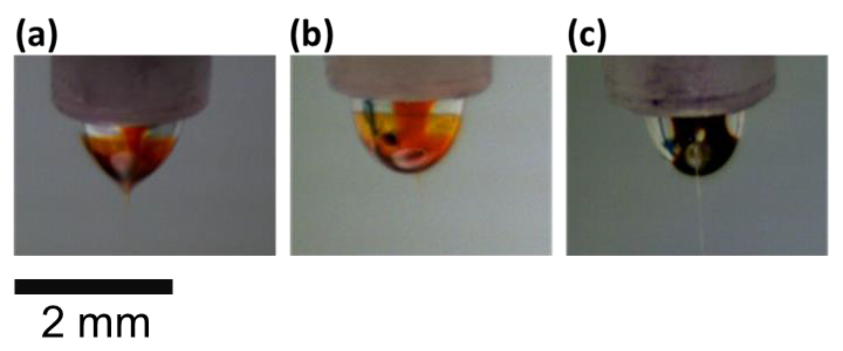
3.1. Solution Rheology

To reveal the intrinsic aggregation features of P3HT chains in different solvent systems, P3HT solutions were diluted to 1 mg·mL−1 for dynamic light scattering (DLS) analysis. The DLS results on the field autocorrelation function, | g ( 1 ) ( q , t ) | , and the associated decay time distribution, A ( q , t ) , for three dilute P3HT solutions are presented in Figure 2. The existence of two distinct relaxation modes can be readily identified in all cases, wherein the first (fast) mode exhibits the usual diffusive motion (i.e.,   Γ ~ q 2 ) while the second (slow) mode demonstrates a peculiar q-independence (i.e., Γ ~ q 0 ). The hydrodynamic radius, R h , estimated from the Stokes–Einstein relation for the fast modes of CF and CB solutions ( R h ~5–8 nm) indicates the dominance (about 99% in weight fraction, as evaluated by the intensity-weight average [26]) of isolated-chain species, whereas the TCB solution bears a substantially greater size ( R h ~60 nm) that can be attributed to crystalline aggregates, as often reported on poorer-solvent media for P3HT [28,29]. The aggregate species clearly is unfavorable for controlling chain orientation in electrospun nanofibers, as we discuss later in the X-ray diffraction (XRD) and photoluminescence (PL) analyses. The q-independent slow mode, ubiquitous in all three P3HT solutions investigated, might reflect the contribution of nondiffusive, microsized clusters that undergo a dynamic condensation/decomposition alternating process [9]. Judged solely by the apparent relaxation time along with the solvent viscosity, the cluster size appears to follow the order: TCB < CF < CB. According to the implied solvent quality in the discussions above on the fast-mode properties, it is likely that the TCB solution produces a smaller, yet more compact, aggregate cluster when compared with the other two. Given, however, that the cluster species is estimated to constitute only about 1% in weight fraction, its impact on ES nanofibers remains unclear.
To facilitate the comparison between different solvent systems, the physical properties of three solvents used in this study and those of the corresponding P3HT solutions are summarized in Table S1 (in Supplementary Materials). It is worth noting that the viscosities of P3HT solutions at a concentration of 50 mg·mL−1 are determined to be 6.22, 5.40 and 21.12 centipoise for CF, CB and TCB systems, respectively, as they represent an essential parameter during electrospinning. Figure 3 show the optical images of a coaxial nozzle during electrospinning for the three solvent systems, where P3HT shows notable color variations in response to the effect of processing solvent. CF and CB are two better solvents for P3HT and result in bright and transparent reddish-orange in the core. TCB is a poorer solvent and results in deep brown in the middle. When CF or CB is used as the solvent, the P3HT solution accumulates on the tip of the Taylor cone and even forms a thin film on the surface layer of the cone. In contrast, the diffusion of core P3HT solution to the outside layer of the cone was prohibited due to the high viscosity of the core solution in the TCB system.

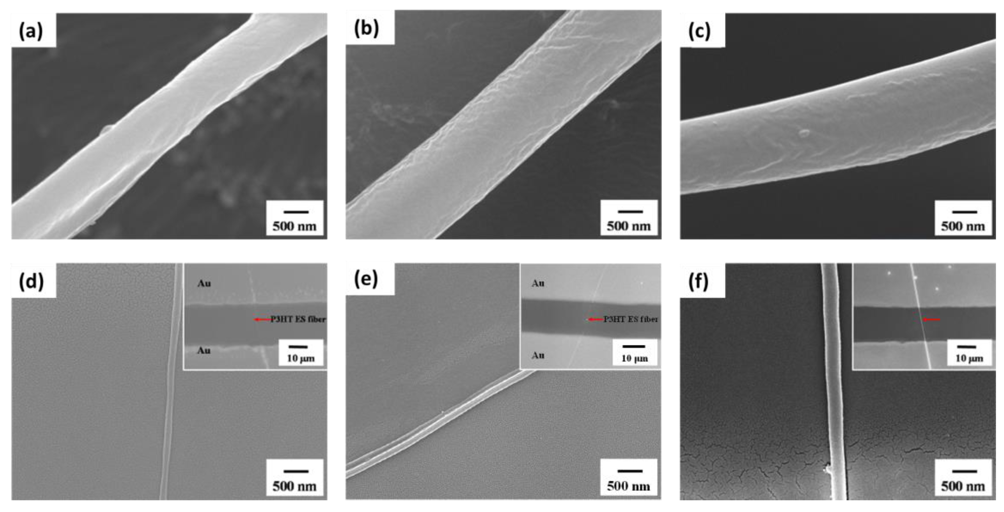
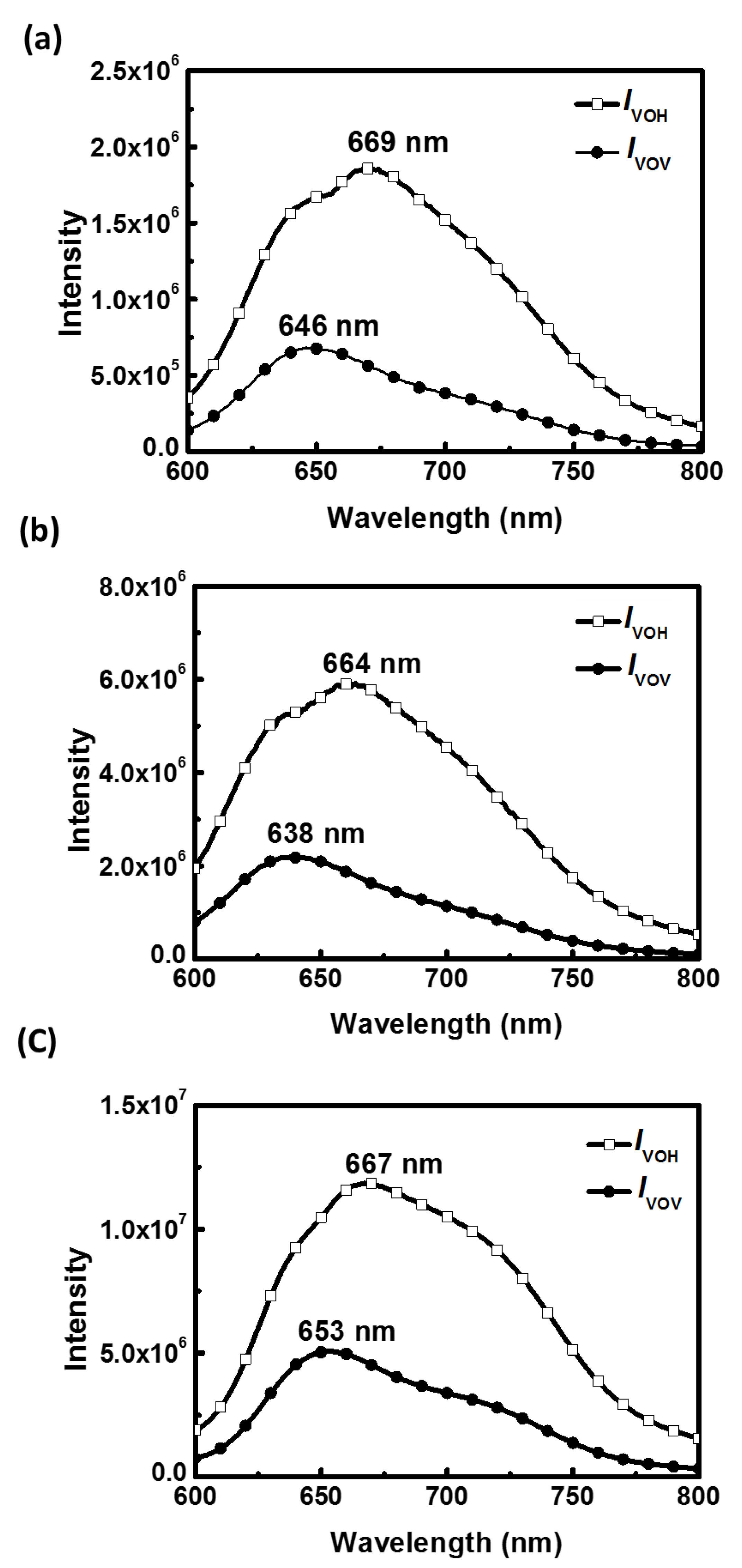
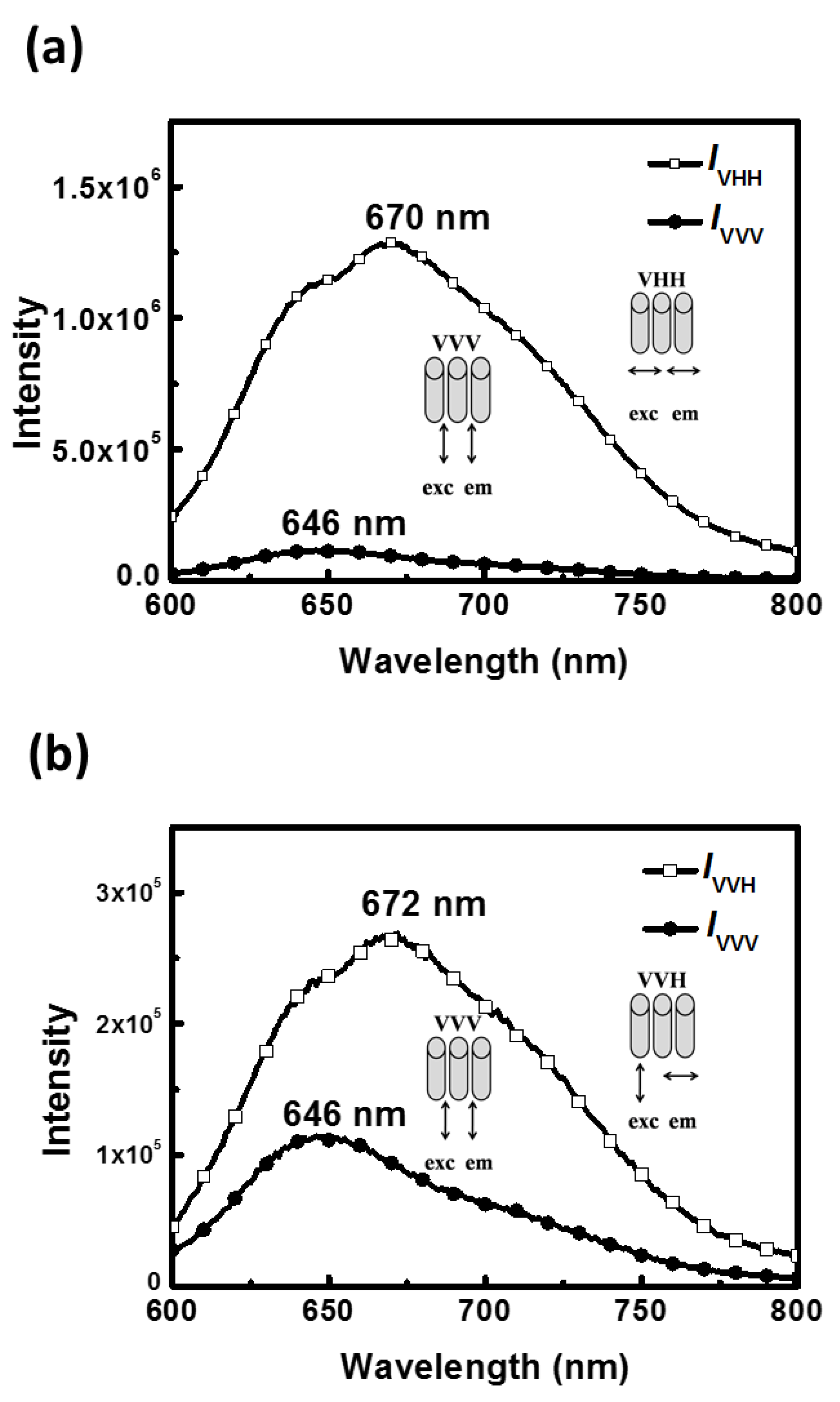
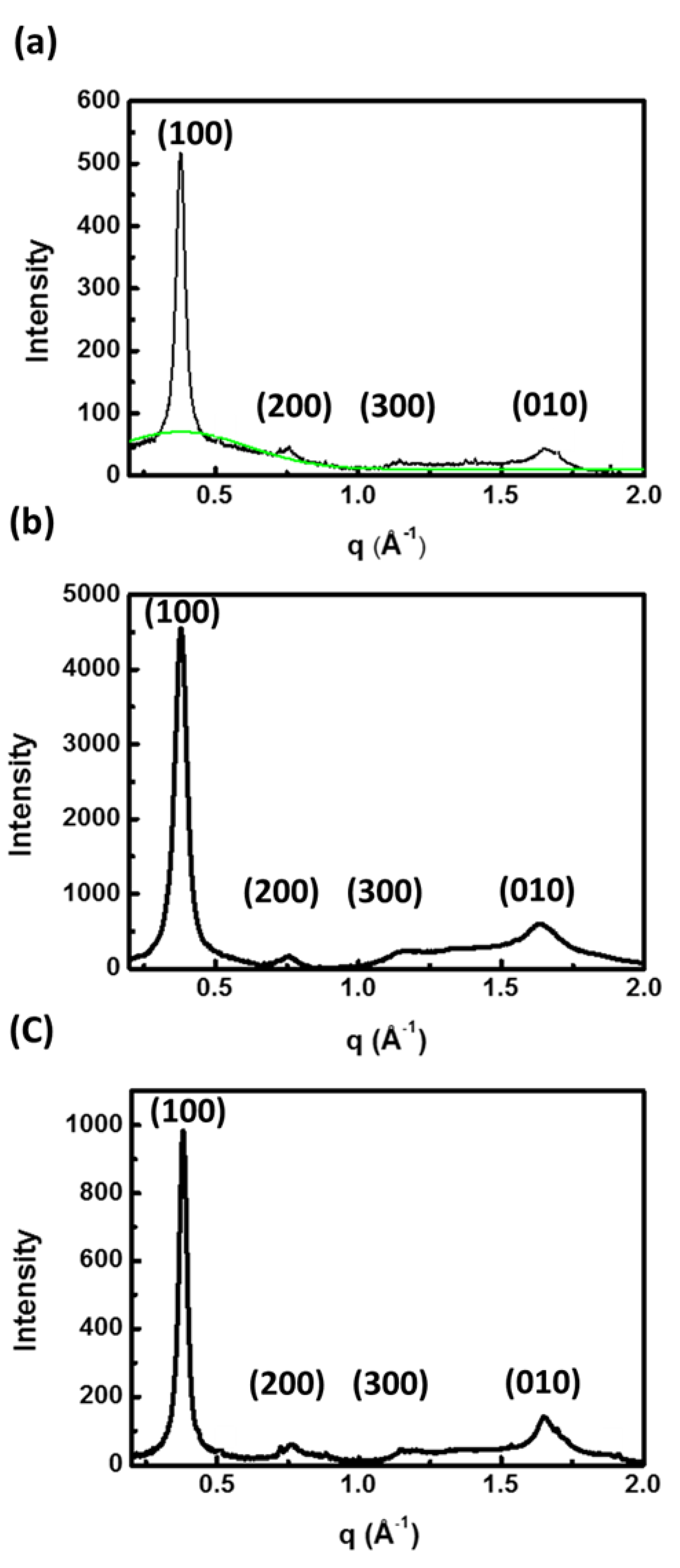
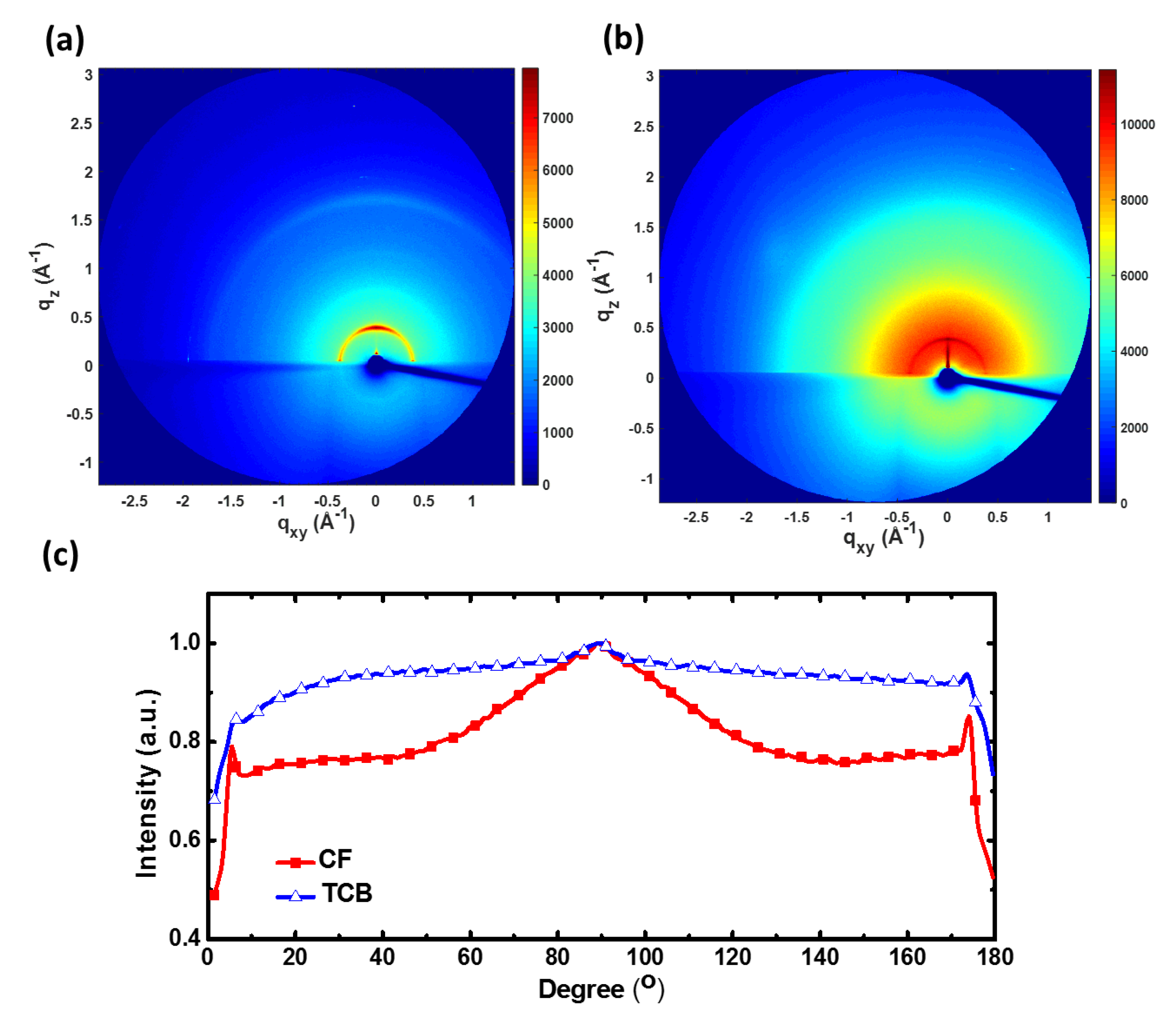
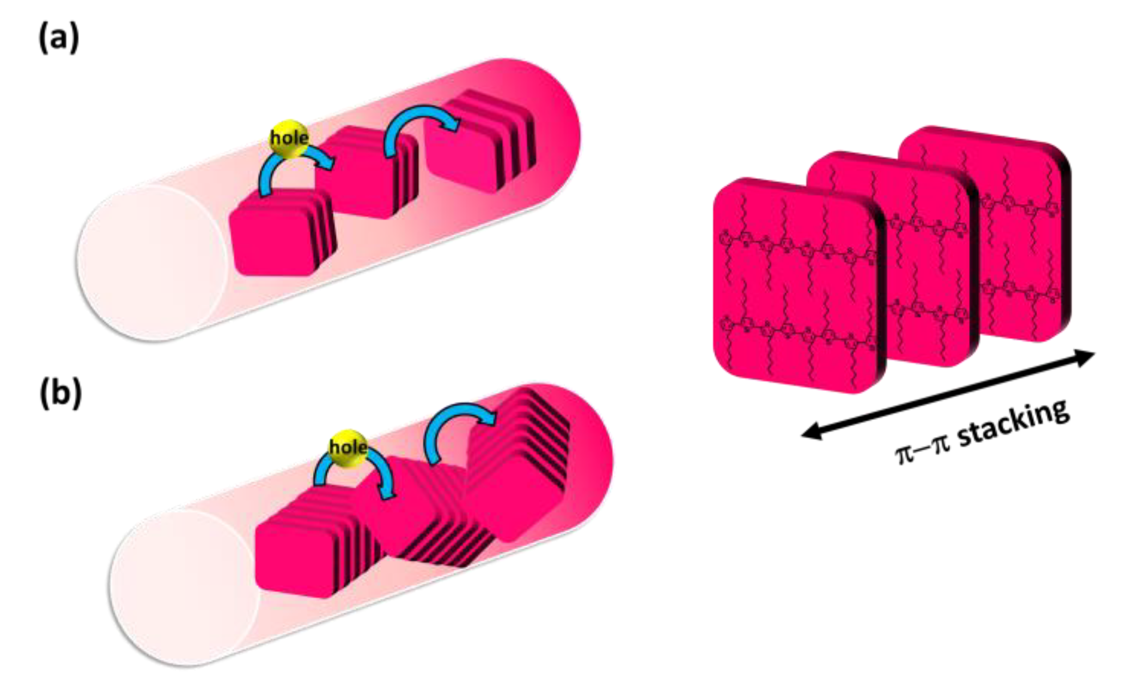
3.2. Morpholgy of P3HT Electrospun Nanofibers

The SEM images shown in Figure 4 indicate that the as-spun coaxial P3HT/PMMA fibers prepared from three different solvents bear a similar diameter of about 1~2 μm. After the removal of the PMMA shell by immersing the fiber in acetone, all of the P3HT electrospun nanofibers are smooth and uniform in appearance because evaporation of the core solvent is prohibited by the shell material, leading to a more stable cone-jet model during the electrospinning process. The diameters of naked P3HT electrospun nanofibers are determined to be 141, 168 and 265 nm for CF, CB and TCB systems, respectively. The pronounced change in diameter for the P3HT electrospun nanofibers can be attributed to the varying degree of polymer aggregation which prohibits P3HT chain stretching during electrospinning.
The UV–Vis absorption spectra of P3HT electrospun nanofibers prepared from the three solvent systems are shown in Figure 5. After normalization by the maximum absorption peak (at wavelength ~550 nm), the intensities of the shoulder (at wavelength ~600 nm) follow the order: CF < CB < TCB. The difference likely reflects the number of ordered aggregates associated with interchain π−π stacking of P3HT [30,31]. According to an early study by Hagler et al., the intensity increase of the shoulder originates from the increase of crystallinity [32]. A high crystallinity in the TCB system is probably due to the severe aggregation of P3HT in the solution, as resolved in prior DLS analysis.
The notable impact of solvent systems for the core polymer can be further observed in polarized photoluminescence (PL) spectra of the aligned P3HT electrospun nanofibers, as shown in Figure 6. The emission polarizations perpendicular and parallel to the nanofiber axis were defined as IVOH and IVOV, respectively. All PL spectra of aligned P3HT electrospun nanofibers prepared from different solvents show polarization anisotropy. When P3HT electrospun nanofibers were excited by an unpolarized light source at a wavelength of 550 nm, the PL polarization ratios (IVOH/IVOV) of 2.72, 2.69 and 2.34 are observed for CF, CB and TCB systems, respectively. In addition, the shifts of PL maximum emission peak between IVOH and IVOV are 23, 26 and 14 nm for CF, CB and TCB systems, respectively. The greater polarization ratios may be attributed to the extended P3HT chain conformation fostered in the CF and CB solutions which can better respond to the elongation force during electrospinning and lead to an enhanced orientation of lamellar spacing after thermal annealing. In contrast, the smallest shift of PL maximum emission peak between IVOH and IVOV in the TCB system indicates the lowest degree of orientation for P3HT chains in electrospun nanofibers.
To further explore the P3HT chain orientation in the CF system, the polarized PL spectra of the P3HT electrospun nanofiber prepared from the CF system were systematically analyzed, as shown in Figure 7. As can be seen, the intensity and emission peak wavelength in the PL spectra respond to the polarizer direction significantly. All PL spectra with the emissions collected perpendicular to the nanofiber (main axis) are red-shifted in the maximum emission wavelength and show stronger intensity compared to the parallel ones regardless of whether the exciting light is parallel or perpendicular with the nanofiber. For example, the polarization ratio IVHH/IVVV attains a value of 11.2 and the perpendicular one (λ = 670 nm) is red-shifted by 24 nm compared to that of the parallel one (λ = 646 nm) (Figure 7a). Interestingly, when the exciting light is polarized parallel to the nanofiber, more light is emitted that is polarized in the direction perpendicular to the nanofiber (Figure 7b).
It has been known that energy can transfer rapidly via Förster transfer within a few picoseconds before emission. Therefore, emission is observed only from the longest, lowest-energy segments [33]. The above features suggest that excitons created on a shorter conjugation segment parallel to the nanofiber axis may migrate to a longer conjugation one that is perpendicular to the nanofiber axis, and then emit red-shifted and polarized light perpendicular to the nanofiber direction. Similar results concerning the perpendicular alignment of backbone have been reported in our previous work [34].
To measure the internal structure of P3HT electrospun nanofibers prepared from different solvent systems, wide-angle X-ray diffraction (WAXD) with transmission-mode was performed. In Figure 8, three ordered structures in the (100) direction labeled as (100), (200) and (300), respectively, which represent the lamella structure, arise from the interdigitation of the hexyl side chain, and the (010) reflection due to π–π interchain stacking is observed in all three solvent systems [34]. Note that P3HT nanofibers prepared from the TCB system have a sharp peak of (100), suggesting a high degree of P3HT crystallinity. It is interesting to note that in the CF system there is a broad amorphous halo under the peak of (100), which signifies the random packing of P3HT and a low degree of crystallinity [7]. Two-dimensional grazing incidence X-ray diffraction (2D-GIXRD) techniques, which measured across P3HT electrospun nanofibers, were employed to examine the orientation of P3HT chain packing in the nanofibers, as shown in Figure 9. The strong (100) diffraction in the qz direction (azimuthal angle = 90°) in the CF system suggests that P3HT chains prevalently adopt an “edge-on” arrangement with respect to the fiber surface. For comparison, the broad azimuthal angle distribution observed for the TCB system is indicative of the random orientation of P3HT chain folding.
According to the features discussed above, we conclude that the polymer aggregates fostered in the TCB solution, while contributing to increased ordering of alkyl chains and enlarged crystal size, lead to poor orientation between the crystalline grains in P3HT electrospun nanofibers, as illustrated in Figure 10b. In contrast, the extended polymer chains fostered in CF and CB solutions help produce highly orientated crystalline grains and smaller crystal size in P3HT electrospun nanofibers, as illustrated in Figure 10a.

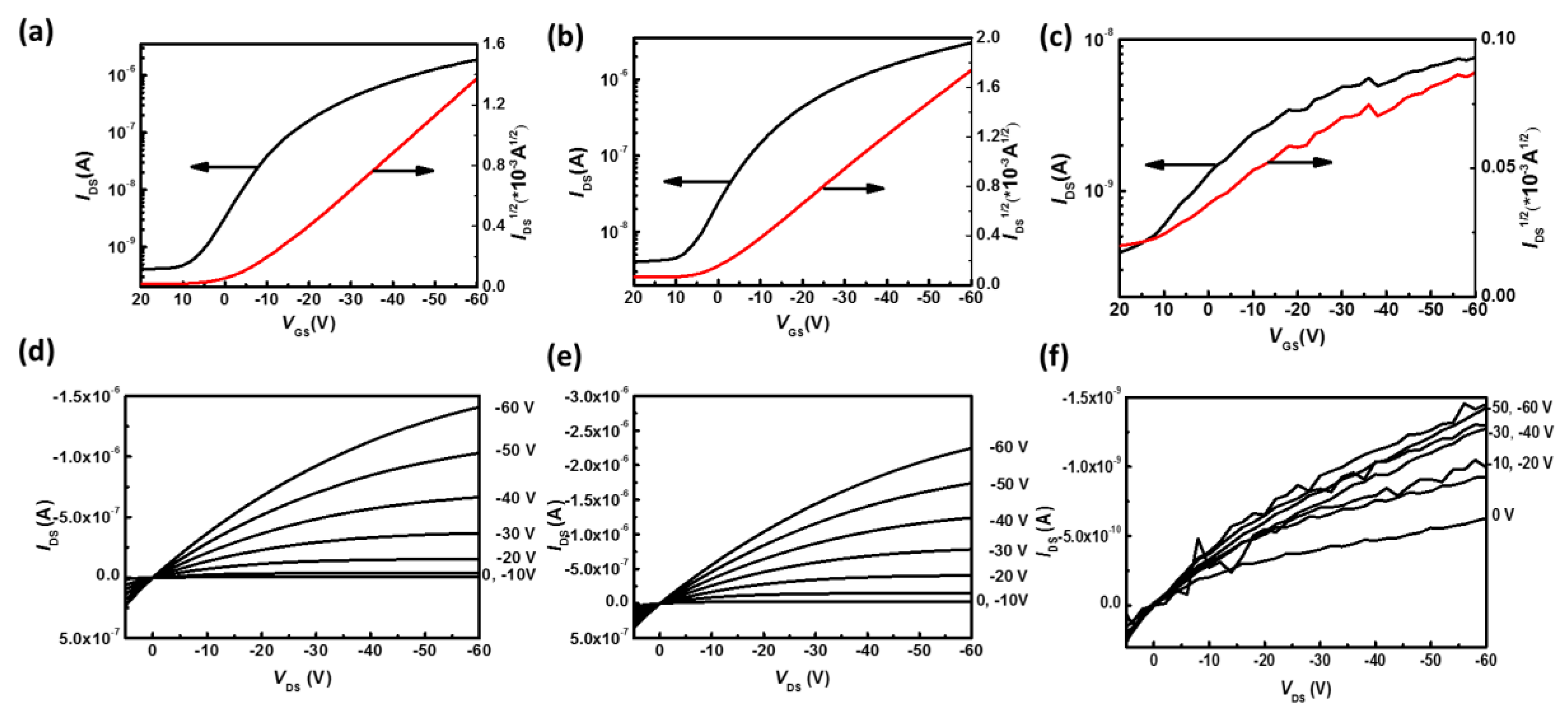
3.3. Electrical Properties of P3HT Electrospun Nanofibers

The transfer and output characteristics of P3HT electrospun nanofiber-based OFETs prepared from the three solvent systems are shown in Figure 11. All of the devices show field-effect characteristics; however, the IDS seems to be unstable for the device prepared from the TCB system. This may be attributed to the poor orientation between crystalline grains in the nanofibers that impedes the hole hopping. Table 1 shows all the electrical properties of the devices mentioned above. From Table 1, the maximum mobilities for the three solvent systems are 3.57 × 10⁻¹, 1.78 × 10⁻¹ and 1.48 × 10⁻⁴ cm2·V−1·s−1, respectively. Intriguingly, the value of the charge-carrier mobility differs by as much as three orders of magnitude and appears to follow distinct trends as compared with those of the degree of crystallinity. The CF system shows the highest mobility despite the fact that its crystallinity remains the lowest, possibly because of the highly ordered orientation between crystalline grains that facilitates charge-carrier hopping through π–π stacking between polymer chains. Table S2 (in Supplementary Materials) summarizes the electrical performances of pure P3HT electrospun nanofiber-based organic field-effect transistors that have been reported in the literature. The results clearly reveal that the core-shell electrospinning technique and the effect of solvent play essential roles in producing high-performance P3HT electrospun nanofiber-based organic field-effect transistors.

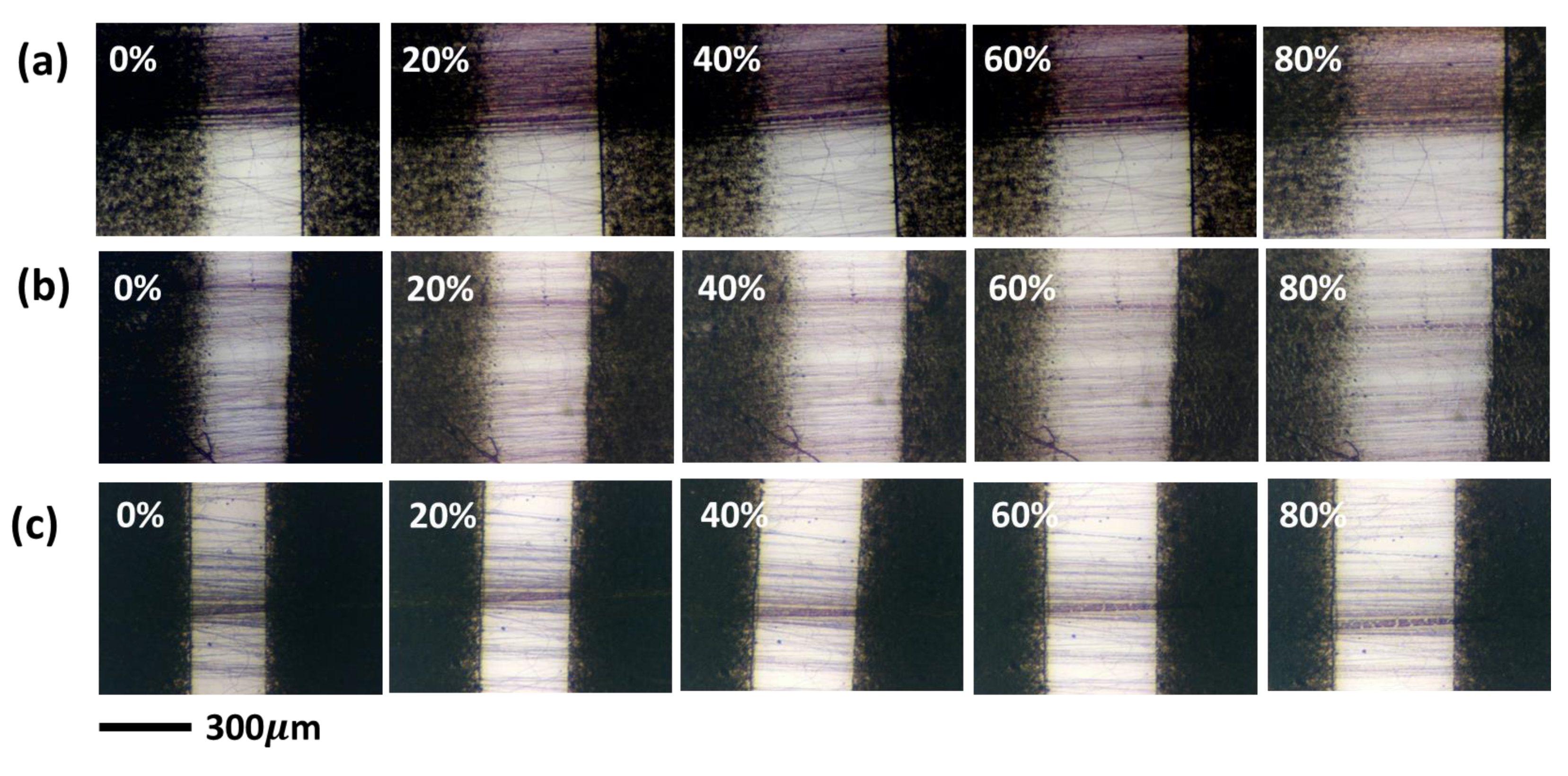
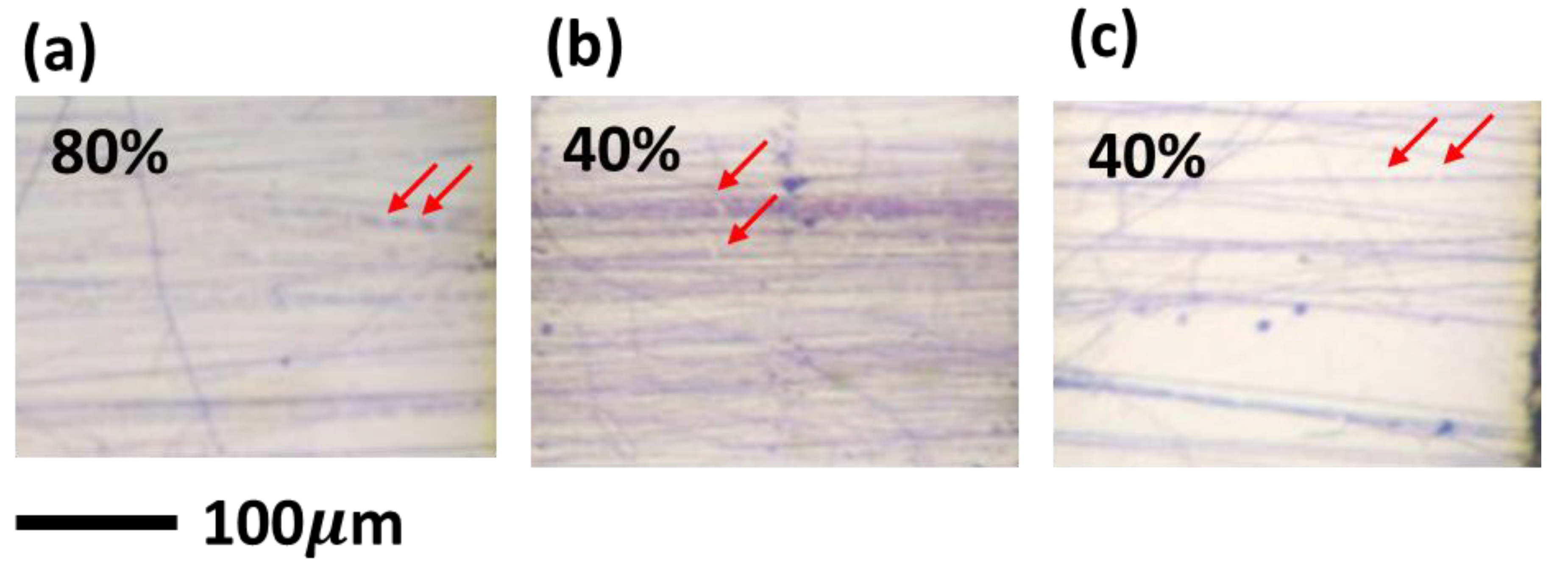
3.4. Ductility Test of P3HT Electrospun Nanofibers

To test the ductility of P3HT electrospun nanofibers, the nanofibers were deposited on polydimethylsiloxane (PDMS) substrate with two spray-coated carbon nanotube (CNT) mats as the gap markers. Figure 12 shows the optical images of the P3HT electrospun nanofibers prepared from different solvent systems when subjected to external strain. All of the aligned P3HT electrospun nanofibers deform along the stretching direction. However, when the strain is increased to 40%, crack formation can be clearly seen for the CB and TCB systems, as shown in Figure 13b,c. In contrast, P3HT electrospun nanofibers prepared from the CF system show superior ductility and crack formation appears only at a much higher strain of 80% (Figure 13a). The delayed crack formation for the CF system may result from the lower crystallinity as the amorphous part can better accommodate the external stress through deformation. Thus, when compared to the other two solvent systems, the CF system seems to achieve the best performance in producing P3HT electrospun nanofibers that possess simultaneously high charge-carrier mobility and decent mechanical ductility.

4. Conclusions

In this study, P3HT nanofiber-based OFETs were successfully prepared by a two-fluid coaxial electrospinning technique with P3HT as the core polymer and PMMA as the shell polymer, followed by extraction of PMMA. Three different solvents for the core polymer—CF, CB and TCB—were employed to manipulate the morphologies and electrical properties of P3HT electrospun nanofibers. The pronounced change in diameter for the P3HT electrospun nanofibers can be attributed to a relatively large viscosity of P3HT solution in the TCB system as a result of the prevalence of aggregate species in solution, which prohibits the diffusion of the core solution into the outside layer and the whipping process during electrospinning. In contrast, the CF system which fosters extended P3HT chains can be readily stretched by the electrical force, resulting in highly oriented crystalline grains and high charge-carrier mobility despite a lower crystallinity and smaller crystal size. The highest charge-carrier mobility thus achieved, 3.57 × 10⁻¹ cm2·V−1·s−1, and the decent mechanical ductility of P3HT electrospun nanofibers fabricated from the CF system suggest the importance of chain stretching during the electrospinning process, whereby favorable orientation of crystalline grains in the electrospun nanofiber can be produced and contributes to excellent electrical properties and mechanical ductility at one time.

Supplementary Materials

The following are available online at https://www.mdpi.com/2073-4360/11/9/1501/s1, Table S1: physical properties of three solvents used in this study and those of the P3HT solutions, Table S2: state-of-the-art electrical performances of pure P3HT electrospun nanofiber-based organic field-effect transistors.

Author Contributions

J.Y.C., C.C.H. and W.C.C. designed the research project. J.Y.C. carried out the experiments and analyzed the data. C.Y.S. and C.L.C. collected and analyzed the dynamic light scattering of P3HT solutions. C.H.H. and Y.H.Z. helped the analysis of the X-ray diffraction. Q.C.Z. helped with the mechanical ductility test. J.Y.C., C.Y.S., C.C.H. and W.C.C. co-wrote the manuscript.

Funding

The authors thank the financial support from the Featured Area Research Center Program within the framework of the Higher Education Sprout Project by the Ministry of Education (107L9006) and the Ministry of Science and Technology in Taiwan (MOST 108-2636-E-194-001-&107-3017-F-002-001).

Conflicts of Interest

The authors declare no conflicts of interest. The funders had no role in the design of the study; in the collection, analyses, or interpretation of data; in the writing of the manuscript, or in the decision to publish the results.

References

  1. Klauk, H. Organic Electronics: Materials, Manufacturing and Applications; Wiley-VCH Publishing: Weinheim, Germany, 2006. [Google Scholar]
  2. Bao, Z.; Locklin, J. Organic Field-Effect Transistors; CRC Press: New York, NY, USA, 2007. [Google Scholar]
  3. Surin, M.; Leclere, P.; Lazzaroni, R.; Yuen, J.D.; Wang, G.; Moses, D.; Heeger, A.J.; Cho, S.; Lee, K. Relationship between the microscopic morphology and the charge transport properties in poly(3-hexylthiophene) field-effect transistors. J. Appl. Phys. 2006, 100, 033712. [Google Scholar] [CrossRef]
  4. Chang, J.-F.; Sun, B.; Breiby, D.W.; Nielsen, M.M.; Solling, T.I.; Giles, M.; McCulloch, I.; Sirringhaus, H. Enhanced mobility of poly(3-hexylthiophene) transistors by spin-coating from high-boiling-point solvents. Chem. Mater. 2004, 16, 4772–4776. [Google Scholar] [CrossRef]
  5. Ma, W.; Yang, C.; Gong, X.; Lee, K.; Heeger, A.J. Thermally stable, efficient polymer solar cells with nanoscale control of the interpenetrating network morphology. Adv. Funct. Mater. 2005, 15, 1617–1622. [Google Scholar] [CrossRef]
  6. Yu, H.Z.; Peng, J.B. Annealed treatment effect in poly(3-hexylthiophene): Methanofullerene solar cells. Chin. Phys. Lett. 2008, 25, 1411. [Google Scholar]
  7. Wu, Z.; Petzold, A.; Henze, T.; Thurn-Albrecht, T.; Lohwasser, R.H.; Sommer, M.; Thelakkat, M. Temperature and molecular weight dependent hierarchical equilibrium structures in semiconducting poly(3-hexylthiophene). Macromolecules 2010, 43, 4646–4653. [Google Scholar] [CrossRef]
  8. Cho, S.; Lee, K.; Yuen, J.; Wang, G.M.; Moses, D.; Heeger, A.J.; Surin, M.; Lazzaroni, R. Thermal annealing-induced enhancement of the field-effect mobility of regioregular poly(3-hexylthiophene) films. J. Appl. Phys. 2006, 100, 114503. [Google Scholar] [CrossRef]
  9. Yi, H.-L.; Hua, C.-C. Peculiar aggregation features in poly(3-hexylthiophene)/chlorobenzene solutions. Macromolecules 2019, 52, 332–340. [Google Scholar] [CrossRef]
  10. Brown, P.J.; Sirringhaus, H.; Harrison, M.; Shkunov, M.; Friend, R.H. Optical spectroscopy of field-induced charge in self-organized high mobility poly(3-hexylthiophene). Phys. Rev. B 2001, 63, 125204. [Google Scholar] [CrossRef]
  11. Brinkmann, M.; Wittmann, J.-C. Orientation of regioregular poly(3-hexylthiophene) by directional solidification: A simple method to reveal the semicrystalline structure of a conjugated polymer. Adv. Mater. 2006, 18, 860–863. [Google Scholar] [CrossRef]
  12. Yang, H.; Shin, T.J.; Yang, L.; Cho, K.; Ryu, C.Y.; Bao, Z. Effect of mesoscale crystalline structure on the field-effect mobility of regioregular poly(3-hexyl thiophene) in thin-film transistors. Adv. Funct. Mater. 2005, 15, 671–676. [Google Scholar] [CrossRef]
  13. Root, S.E.; Savagatrup, S.; Printz, A.D.; Rodriquez, D.; Lipomi, D.J. Mechanical properties of organic semiconductors for stretchable, highly flexible, and mechanically robust electronics. Chem. Rev. 2017, 117, 6467–6499. [Google Scholar] [CrossRef] [PubMed]
  14. Ho, V.; Boudouris, B.W.; Segalman, R.A. Tuning polythiophene crystallization through systematic side chain functionalization. Macromolecules 2010, 43, 7895–7899. [Google Scholar] [CrossRef]
  15. Li, D.; Xia, Y. Direct fabrication of composite and ceramic hollow nanofibers by electrospinning. Nano Letters 2004, 4, 933–938. [Google Scholar] [CrossRef]
  16. Babel, A.; Li, D.; Xia, Y.N.; Jenekhe, S.A. Electrospun nanofibers of blends of conjugated polymers: Morphology, optical properties, and field-effect transistors. Macromolecules 2005, 38, 4705–4711. [Google Scholar] [CrossRef]
  17. Chen, J.-Y.; Wu, H.-C.; Chiu, Y.-C.; Lin, C.-J.; Tung, S.-H.; Chen, W.-C. Electrospun poly(3-hexylthiophene) nanofibers with highly extended and oriented chains through secondary electric field for high-performance field-effect transistors. Adv. Electron. Mater. 2015, 1, 1400028. [Google Scholar] [CrossRef]
  18. Chen, J.-Y.; Chiu, Y.-C.; Shih, C.-C.; Wu, W.-C.; Chen, W.-C. Electrospun nanofibers with dual plasmonic-enhanced luminescent solar concentrator effects for high-performance organic photovoltaic cells. J. Mater. Chem. A 2015, 3, 15039–15048. [Google Scholar] [CrossRef]
  19. Chen, J.-Y.; Wu, H.-C.; Chiu, Y.-C.; Chen, W.-C. Plasmon-enhanced polymer photovoltaic device performance using different patterned Ag/PVP electrospun nanofibers. Adv. Energy Mater. 2014, 4, 1301665. [Google Scholar] [CrossRef]
  20. Tsai, P.-C.; Chen, J.-Y.; Ercan, E.; Chueh, C.-C.; Tung, S.-H.; Chen, W.-C. Uniform luminous perovskite nanofibers with color-tunability and improved stability prepared by one-step core/shell electrospinning. Small 2018, 14, 1704379. [Google Scholar] [CrossRef]
  21. Kuo, C.-C.; Wang, C.-T.; Chen, W.-C. Highly-aligned electrospun luminescent nanofibers prepared from polyfluorene/PMMA blends: Fabrication, morphology, photophysical properties and sensory applications. Macromol. Mater. Eng. 2008, 293, 999–1008. [Google Scholar] [CrossRef]
  22. Li, D.; Wang, Y.; Xia, Y. Electrospinning of polymeric and ceramic nanofibers as uniaxially aligned arrays. Nano Lett. 2003, 3, 1167–1171. [Google Scholar] [CrossRef]
  23. Li, D.; Wang, Y.; Xia, Y. Electrospinning nanofibers as uniaxially aligned arrays and layer-by-layer stacked films. Adv. Mater. 2004, 16, 361–366. [Google Scholar] [CrossRef]
  24. Wen, Y.H.; Lin, P.C.; Hua, C.C.; Chen, S.A. Dynamic structure factor for large aggregate clusters with internal motions: A self-consistent light-scattering study on conjugated polymer solutions. J. Phys. Chem. B 2011, 115, 14369–14380. [Google Scholar] [CrossRef] [PubMed]
  25. Guo, R.H.; Hsu, C.H.; Hua, C.C.; Chen, S.A. Colloidal aggregate and gel incubated by amorphous conjugated polymer in hybrid-solvent medium. J. Phys. Chem. B 2015, 119, 3320–3331. [Google Scholar] [CrossRef] [PubMed]
  26. Yi, H.L.; Wu, C.H.; Wang, C.I.; Hua, C.C. Solvent-regulated mesoscale aggregation properties of dilute PBTTT-C14 solutions. Macromolecules 2017, 50, 5498–5509. [Google Scholar] [CrossRef]
  27. Liu, H.Q.; Reccius, C.H.; Craighead, H.G. Single electrospun regioregular poly(3-hexylthiophene) nanofiber field-effect transistor. Appl. Phys. Lett. 2005, 87, 253106. [Google Scholar] [CrossRef]
  28. Liu, J.; Shao, S.; Wang, H.; Zhao, K.; Xue, L.; Gao, X.; Xie, Z.; Han, Y. The mechanisms for introduction of n-dodecylthiol to modify the P3HT/PCBM morphology. Org. Electron. 2010, 11, 775–783. [Google Scholar] [CrossRef]
  29. Xue, L.; Yu, X.; Han, Y. Different structures and crystallinities of poly(3-hexylthiophene) films prepared from aged solutions. Colloids Surf. A 2011, 380, 334–340. [Google Scholar] [CrossRef]
  30. Berson, S.; De Bettignies, R.; Bailly, S.; Guillerez, S. Poly(3-hexylthiophene) Fibers for Photovoltaic Applications. Adv. Funct. Mater. 2007, 17, 1377–1384. [Google Scholar] [CrossRef]
  31. Zhang, J.; Wang, C.; Chen, W.; Wu, J.; Zhang, Q. Fabrication and physical properties of self-assembled ultralong polymer/small molecule hybrid microstructures. RSC Adv. 2015, 5, 25550–25554. [Google Scholar] [CrossRef]
  32. Hagler, T.W.; Pakbaz, K.; Voss, K.F.; Heeger, A.J. Enhanced order and electronic delocalization in conjugated polymers oriented by gel processing in polyethylene. Phys. Rev. B 1991, 44, 8652. [Google Scholar] [CrossRef]
  33. Nguyen, T.-Q.; Wu, J.; Doan, V.; Schwartz, B.J.; Tolbert, S.H. Control of energy transfer in oriented conjugated polymer-mesoporous silica composites. Science 2000, 288, 652–656. [Google Scholar] [CrossRef] [PubMed]
  34. Chen, J.-Y.; Kuo, C.-C.; Lai, C.-S.; Chen, W.-C.; Chen, H.-L. Manipulation on the morphology and electrical properties of aligned electrospun nanofibers of poly(3-hexylthiophene) for field-effect transistor applications. Macromolecules 2011, 44, 2883–2892. [Google Scholar] [CrossRef]
Figure 1. Schematic of the coaxial electrospinning setup and poly(3-hexylthiophene-2,5-diyl) (P3HT) electrospun nanofiber-based organic field-effect transistors (OFETs). Abbreviations: PMMA, poly(methyl methacrylate).
Polymers 11 01501 g001
Figure 2. Angular dependences of the field autocorrelation function and the associated decay time distribution extracted from Constrained Regularization Method for Inverting Data (CONTIN) for 1 mg·mL−1 P3HT solutions prepared with (a) chloroform (CF); (b) chlorobenzene (CB) and (c) 1,2,4-trichlorobenzene (TCB) media, where the decay time t has been rescaled with q2. The right column shows the scaling relationship between the mean decay rate ( Γ ) and the scattering vector (q) (i.e., Γ ~ q α ), which can be utilized to identify the attribute of a particular relaxation mode (e.g., α = 2 for diffusive motions).
Polymers 11 01501 g002
Figure 3. Charge-coupled Device (CCD) images of Taylor cone in (a) CF, (b) CB and (c) TCB systems.
Polymers 11 01501 g003
Figure 4. Scanning electronic microscopy (SEM) images of as-spun P3HT/PMMA fibers prepared from (a) CF; (b) CB and (c) TCB systems. The corresponding pure P3HT nanofibers prepared from (d) CF; (e) CB and (f) TCB systems after removing the PMMA shell. The inset SEM figures show the typical transistor fabricated by the respective P3HT nanofibers.
Polymers 11 01501 g004
Figure 5. Optical absorption spectra of P3HT electrospun nanofibers prepared from three different solvent systems.
Polymers 11 01501 g005
Figure 6. Polarized photoluminescence spectra of the aligned P3HT electrospun nanofibers, with an isotropic exciting light source and the corresponding emission collected for the perpendicular (IVOH) or parallel (IVOV) polarization with respect to the fiber axis for (a) CF; (b) CB and (c) TCB systems.
Polymers 11 01501 g006
Figure 7. Polarized photoluminescence spectra of the aligned P3HT electrospun nanofibers prepared from the CF system with (a) the exciting light and the corresponding emission polarized in the perpendicular (IVHH) or parallel (IVVV) direction with respect to the fiber axis and (b) the exciting light polarized in the parallel direction with respect to the fiber axis, and the corresponding emission polarized in the perpendicular (IVVH) or parallel (IVVV) direction with respect to the fiber axis.
Polymers 11 01501 g007
Figure 8. Transmission-mode X-ray diffraction patterns of nanofibers prepared from (a) CF, (b) CB and (c) TCB systems.
Polymers 11 01501 g008
Figure 9. Two-dimensional grazing incidence X-ray diffraction (2D-GIXRD) patterns of P3HT electrospun nanofibers prepared from (a) CF and (b) TCB systems. (c) Azimuthal angle analysis of (100) lamellar packing for CF and TCB systems.
Polymers 11 01501 g009
Figure 10. Schematic illustrations of the chain packing and crystalline grain orientation in P3HT electrospun nanofibers prepared from (a) CF or CB and (b) TCB systems, where the red bricks demonstrate the 2D planes from the thiophene rings.
Polymers 11 01501 g010
Figure 11. Transfer (IDS and IDS1/2 versus VGS at VDS = −60 V) and output characteristics of P3HT electrospun nanofibers prepared from (a,d) CF; (b,e) CB and (c,f) TCB systems.
Polymers 11 01501 g011
Figure 12. Ductility test of P3HT electrospun nanofibers prepared from (a) CF, (b) CB and (c) TCB systems. The red arrows indicate the crack formation.
Polymers 11 01501 g012
Figure 13. Enlarged optical images of crack formation for (a) CF, (b) CB and (c) TCB system. The red arrows demonstrate the location of crack formation.
Polymers 11 01501 g013
Table 1. Diameters and electrical properties of the devices prepared from three different solvent systems.
Shell Flow Rate
(ml·h−1)
Diameter (nm)Mobility
(cm2·V−1·s−1)
On Current
(A)
Off Current
(A)
On/Off
(-)
VTH
(V)
CF1413.57 × 10−19.42 × 10−72.06 × 10−104.57 × 10³−2.5
CB1681.78 × 10−14.33 × 10−75.74 × 10−107.54 × 1023.3
TCB2651.48 × 10−41.09 × 10−95.60 × 10−111.94 × 10140

