Enriched Mechanical Strength and Bone Mineralisation of Electrospun Biomimetic Scaffold Laden with Ylang Ylang Oil and Zinc Nitrate for Bone Tissue Engineering

Abstract
1. Introduction
2. Experimental Section
2.1. Materials
2.2. Preparation of PU and Their Composite Solution
2.3. Electrospinning of Prepared Solutions
2.4. Characterization
2.4.1. Field Emission Scanning Electron Microscopy (FESEM)
2.4.2. Fourier Transform Infrared Spectroscopy (FTIR)
2.4.3. Contact Angle Measurements
2.4.4. X-ray Diffraction
2.4.5. Thermal Behaviour
2.4.6. Tensile Test Analysis
2.4.7. Atomic Force Microscopy (AFM) Analysis
2.5. Mineralization Testing
2.6. Coagulation Assays
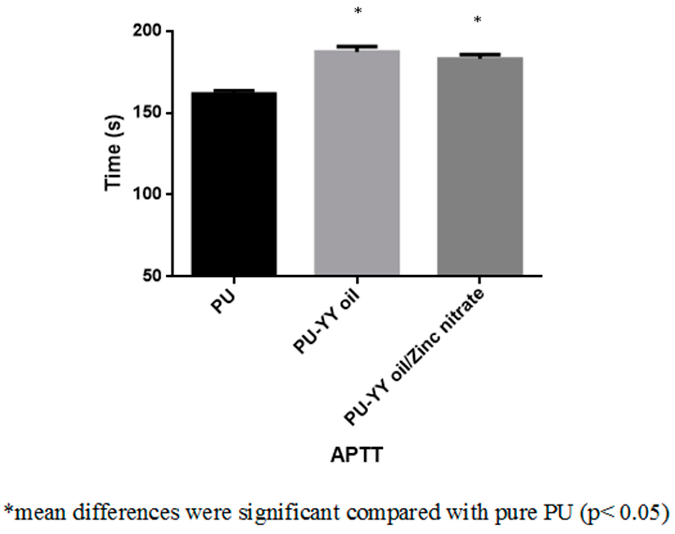
2.6.1. Activated Partial Thromboplastin Time (APTT) Assay
2.6.2. Prothrombin Time (PT) Assay
2.6.3. Hemolysis Assay
2.7. MTS Assay
2.8. Statistical Analysis
3. Results and Discussion
3.1. SEM Investigation
3.2. IR Analysis
3.3. Contact Angle Measurements
3.4. XRD Analysis
3.5. Thermal Analysis
3.6. Mechanical Properties
3.7. AFM Analysis
3.8. Coagulation Assessments
3.9. Bone Mineralization Testing
3.10. Cytocompatibility Analysis
4. Conclusions
Author Contributions
Funding
Conflicts of Interest
References
- Qi, J.; Zhang, H.; Wang, Y.; Mani, M.P.; Jaganathan, S.K. Development and blood compatibility assessment of electrospun polyvinyl alcohol blended with metallocene polyethylene and plectranthus amboinicus (PVA/mPE/PA) for bone tissue engineering. Int. J. Nanomed. 2018, 13, 2777–2788. [Google Scholar] [CrossRef] [PubMed]
- Bone Regeneration. Available online: https://www.sciencedirect.com/topics/medicine-and-dentistry/bone-regeneration (accessed on 2 July 2019).
- Son, S.R.; Linh, N.T.; Yang, H.M.; Lee, B.T. In vitro and in vivo evaluation of electrospun PCL/PMMA fibrous scaffolds for bone regeneration. Sci. Technol. Adv. Mater. 2013, 14, 015009. [Google Scholar] [CrossRef] [PubMed]
- Thavornyutikarn, B.; Chantarapanich, N.; Sitthiseripratip, K.; Thouas, G.A.; Chen, Q. Bone tissue engineering scaffolding: Computer-aided scaffolding techniques. Prog. Biomater. 2014, 3, 61–102. [Google Scholar] [CrossRef] [PubMed]
- Chan, B.P.; Leong, K.W. Scaffolding in tissue engineering: General approaches and tissue-specific considerations. Eur. Spine J. 2008, 17, 467–479. [Google Scholar] [CrossRef] [PubMed]
- Sill, T.J.; Von Recum, H.A. Electrospinning: Applications in drug delivery and tissue engineering. Biomaterials 2008, 29, 1989–2006. [Google Scholar] [CrossRef] [PubMed]
- Voytik-Harbin, S.L. Chapter 26 Three-dimensional extracellular matrix substrates for cell culture. Methods Cell Biol. 2001, 63, 561–581. [Google Scholar] [PubMed]
- Bhattarai, R.; Bachu, R.; Boddu, S.; Bhaduri, S. Biomedical applications of electrospun nanofibers: Drug and nanoparticle delivery. Pharmaceutics 2019, 11, 5. [Google Scholar] [CrossRef] [PubMed]
- Subbiah, T.; Bhat, G.S.; Tock, R.W.; Parameswaran, S.; Ramkumar, S.S. Electrospinning of nanofibers. J. Appl. Polym. Sci. 2005, 96, 557–569. [Google Scholar] [CrossRef]
- Huang, Z.-M.; Zhang, Y.-Z.; Kotaki, M.; Ramakrishna, S.; Zhang, Y. A review on polymer nanofibers by electrospinning and their applications in nanocomposites. Compos. Sci. Technol. 2003, 63, 2223–2253. [Google Scholar] [CrossRef]
- Wu, S.-C.; Chang, W.-H.; Dong, G.-C.; Chen, K.-Y.; Chen, Y.-S.; Yao, C.-H. Cell adhesion and proliferation enhancement by gelatin nanofiber scaffolds. J. Bioact. Compat. Polym. 2011, 26, 565–577. [Google Scholar] [CrossRef]
- Polymer Properties Database. Available online: https://polymerdatabase.com/polymer%20classes/Polyurethane%20type.html (accessed on 29 April 2019).
- Shen, Z.; Lu, D.; Li, Q.; Zhang, Z.; Zhu, Y. Synthesis and Characterization of Biodegradable Polyurethane for Hypopharyngeal Tissue Engineering. BioMed Res. Int. 2015, 2015, 1–11. [Google Scholar] [CrossRef] [PubMed]
- Kumar, N.S.; Santhosh, C.; Sudakaran, S.V.; Deb, A.; Raghavan, V.; Venugopal, V.; Bhatnagar, A.; Bhat, S.; Andrews, N.G. Electrospun polyurethane and soy protein nanofibres for wound dressing applications. IET Nanobiotechnol. 2017, 12, 94–98. [Google Scholar] [CrossRef]
- Gencturk, A.; Kahraman, E.; Güngör, S.; Özhan, G.; Özsoy, Y.; Sarac, A.S. Polyurethane/hydroxypropyl cellulose electrospun nanofiber mats as potential transdermal drug delivery system: Characterization studies and in vitro assays. Artif. Cells Nanomed. Biotechnol. 2017, 45, 655–664. [Google Scholar] [CrossRef] [PubMed]
- Gabriel, L.P.; Rodrigues, A.A.; Macedo, M.; Jardini, A.L.; Filho, R.M. Electrospun polyurethane membranes for Tissue Engineering applications. Mater. Sci. Eng. C 2017, 72, 113–117. [Google Scholar] [CrossRef] [PubMed]
- Jaganathan, S.K.; Mani, M.P.; Nageswaran, G.; Krishnasamy, N.P.; Ayyar, M. Single stage electrospun multicomponent scaffold for bone tissue engineering application. Polym. Test. 2018, 70, 244–254. [Google Scholar] [CrossRef]
- Jaganathan, S.K.; Mani, M.P.; Palaniappan, S.K.; Rathanasamy, R. Fabrication and characterisation of nanofibrous polyurethane scaffold incorporated with corn and neem oil using single stage electrospinning technique for bone tissue engineering applications. J. Polym. Res. 2018, 25, 146. [Google Scholar] [CrossRef]
- Chao, C.Y.; Mani, M.P.; Jaganathan, S.K. Engineering electrospun multicomponent polyurethane scaffolding platform comprising grapeseed oil and honey/propolis for bone tissue regeneration. PLoS ONE 2018, 13, e0205699. [Google Scholar] [CrossRef]
- De Silva, R.T.; Mantilaka, M.M.M.G.P.G.; Goh, K.L.; Ratnayake, S.P.; Amaratunga, G.A.J.; De Silva, K.M.N. Magnesium Oxide Nanoparticles Reinforced Electrospun Alginate-Based Nanofibrous Scaffolds with Improved Physical Properties. Int. J. Biomater. 2017, 2017, 1–9. [Google Scholar] [CrossRef]
- Rodriguez-Tobias, H.; Morales, G.; Ledezma, A.; Romero, J.; Grande, D. Novel antibacterial electrospun mats based on poly(d,l-lactide) nanofibers and zinc oxide nanoparticles. J. Mater. Sci. 2014, 49, 8373–8385. [Google Scholar] [CrossRef]
- Tan, L.T.H.; Lee, L.H.; Yin, W.F.; Chan, C.K.; Kadir, H.A.; Chan, K.G.; Goh, B.H. Traditional Uses, Phytochemistry, and Bioactivities of Cananga odorata (Ylang-Ylang). Evidence-Based Complement. Altern. Med. 2015, 2015, 1–30. [Google Scholar]
- Forero, J.C.; Roa, E.; Reyes, J.G.; Acevedo, C.; Osses, N. Development of Useful Biomaterial for Bone Tissue Engineering by Incorporating Nano-Copper-Zinc Alloy (nCuZn) in Chitosan/Gelatin/Nano-Hydroxyapatite (Ch/G/nHAp) Scaffold. Materials 2017, 10, 1177. [Google Scholar] [CrossRef] [PubMed]
- Linh, N.T.; Lee, B.T. Electrospinning of polyvinyl alcohol/gelatin nanofiber composites and cross-linking for bone tissue engineering application. J. Biomater. Appl. 2012, 27, 255–266. [Google Scholar] [CrossRef] [PubMed]
- Prabhakaran, M.P.; Venugopal, J.; Ramakrishna, S. Electrospun nanostructured scaffolds for bone tissue engineering. Acta Biomater. 2009, 5, 2884–2893. [Google Scholar] [CrossRef] [PubMed]
- Lawrence, B.J.; Madihally, S.V. Cell colonization in degradable 3D porous matrices. Cell Adhes. Migr. 2008, 2, 9–16. [Google Scholar] [CrossRef] [PubMed]
- Noriega, S.E.; Hasanova, G.I.; Schneider, M.J.; Larsen, G.F.; Subramanian, A. Effect of fiber diameter on the spreading, proliferation and differentiation of chondrocytes on electrospun chitosan matrices. Cells Tissues Organs 2012, 195, 207–221. [Google Scholar] [CrossRef] [PubMed]
- Guo, Z.; Ma, M.; Huang, X.; Li, H.; Zhou, C. Effect of Fiber Diameter on Proliferation and Differentiation of MC3T3-E1 Pre-Osteoblasts. J. Biomater. Tissue Eng. 2017, 7, 162–169. [Google Scholar] [CrossRef]
- Mani, M.P.; Jaganathan, S.K. Physicochemical and blood compatibility characteristics of garlic incorporated polyurethane nanofibrous scaffold for wound dressing applications. J. Text. Inst. 2019, 6, 1–9. [Google Scholar] [CrossRef]
- Unnithan, A.R.; Pichiah, P.T.; Gnanasekaran, G.; Seenivasan, K.; Barakat, N.A.; Cha, Y.-S.; Jung, C.-H.; Shanmugam, A.; Kim, H.Y. Emu oil-based electrospun nanofibrous scaffolds for wound skin tissue engineering. Colloids Surfaces A Physicochem. Eng. Asp. 2012, 415, 454–460. [Google Scholar] [CrossRef]
- Wei, J.; Igarashi, T.; Okumori, N.; Igarashi, T.; Maetani, T.; Liu, B.; Yoshinari, M. Influence of surface wettability on competitive protein adsorption and initial attachment of osteoblasts. Biomed. Mater. 2009, 4, 45002. [Google Scholar] [CrossRef]
- Liang, C.; Luo, Y.; Yang, G.; Xia, D.; Liu, L.; Zhang, X.; Wang, H. Graphene Oxide Hybridized nHAC/PLGA Scaffolds Facilitate the Proliferation of MC3T3-E1 Cells. Nanoscale Res. Lett. 2018, 13, 15. [Google Scholar] [CrossRef]
- Zhang, Y.; Zhu, F.; Zhang, J.; Xia, L. Converting Layered Zinc Acetate Nanobelts to One-dimensional Structured ZnO Nanoparticle Aggregates and their Photocatalytic Activity. Nanoscale Res. Lett. 2008, 3, 201–204. [Google Scholar] [CrossRef]
- Jaganathan, S.K.; Mani, M.P. Single-stage synthesis of electrospun polyurethane scaffold impregnated with zinc nitrate nanofibers for wound healing applications. J. Appl. Polym. Sci. 2019, 136, 46942. [Google Scholar] [CrossRef]
- Jaganathan, S.K.; Mani, M.P. Electrospun polyurethane nanofibrous composite impregnated with metallic copper for wound-healing application. 3 Biotech 2018, 8, 327. [Google Scholar] [CrossRef] [PubMed]
- Salifu, A.A.; Lekakou, C.; Labeed, F.H. Electrospun oriented gelatin-hydroxyapatite fiber scaffolds for bone tissue engineering. J. Biomed. Mater. Res. Part. A 2017, 105, 1911–1926. [Google Scholar] [CrossRef] [PubMed]
- Anatomy and Physiology. Available online: https://opentextbc.ca/anatomyandphysiology/chapter/6-3-bone-structure/ (accessed on 2 July 2019).
- Kim, H.H.; Kim, M.J.; Ryu, S.J.; Ki, C.S.; Park, Y.H. Effect of fiber diameter on surface morphology, mechanical property, and cell behavior of electrospun poly (ε-caprolactone) mat. Fiber Polym. 2016, 17, 1033–1042. [Google Scholar] [CrossRef]
- Ribeiro, C.; Sencadas, V.; Areias, A.C.; Gama, F.M.; Lanceros-Méndez, S. Surface roughness dependent osteoblast and fibroblast response on poly (l-lactide) films and electrospun membranes. J. Biomed. Mater. Res. Part. A 2015, 103, 2260–2268. [Google Scholar] [CrossRef]
- Szycher, M. High Performance Biomaterials: A Complete Guide to Medical and Pharmceutical Applications; Routledge: London, UK, 2017. [Google Scholar]
- Tian, F.; Hosseinkhani, H.; Hosseinkhani, M.; Khademhosseini, A.; Yokoyama, Y.; Estrada, G.G.; Kobayashi, H. Quantitative analysis of cell adhesion on aligned micro-and nanofibers. J. Biomed. Mater. Res. Part. A 2008, 84, 291–299. [Google Scholar] [CrossRef]
- Nandakumar, V.; Suresh, G.; Chittaranjan, S.; Doble, M. Synthesis and Characterization of Hydrophilic High Glycolic Acid–Poly(d,l-Lactic-co-Glycolic Acid)/Polycaprolactam/Polyvinyl Alcohol Blends and Their Biomedical Application as a Ureteral Material. Ind. Eng. Chem. Res. 2012, 52, 751–760. [Google Scholar] [CrossRef]
- Periosteum. Available online: https://en.wikipedia.org/wiki/Periosteum (accessed on 2 July 2019).


| S.NO | Polyurethane (PU) | PU/Ylang Ylang (YY) | PU/YY/Zinc Nitrate (ZnNO3) |
|---|---|---|---|
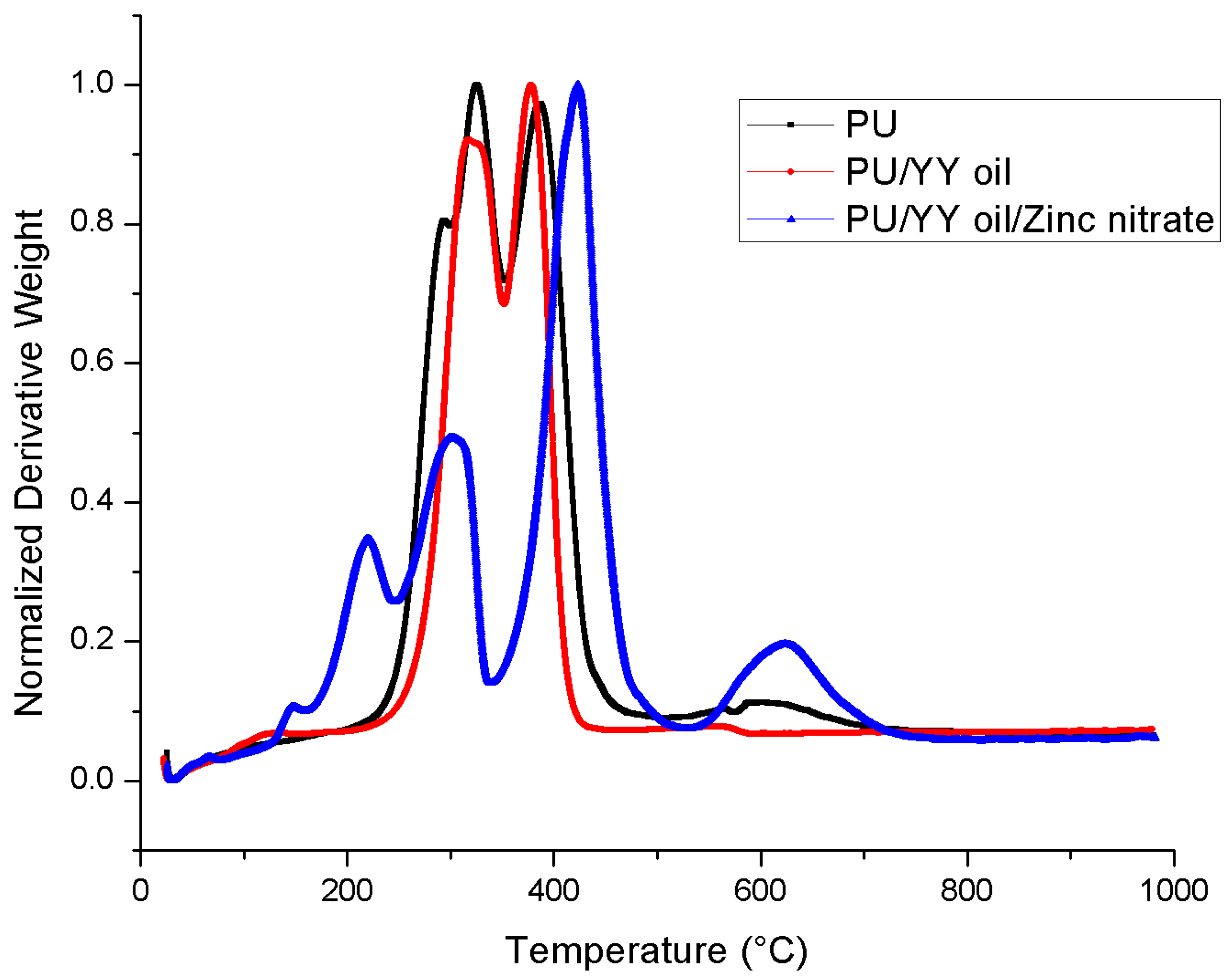
| First weight loss | 210 °C to 302 °C | 225 °C to 351 °C | 119 °C to 161 °C |
| Second weight loss | 302 °C to 353 °C | 351 °C to 470 °C | 161 °C to 246 °C |
| Third weight loss | 353 °C to 494 °C | - | 246 °C to 339 °C |
| Fourth weight loss | 494 °C to 760 °C | - | 339 °C to 530 °C |
| Fifth weight loss | - | - | 530 °C to 780 °C |
© 2019 by the authors. Licensee MDPI, Basel, Switzerland. This article is an open access article distributed under the terms and conditions of the Creative Commons Attribution (CC BY) license (http://creativecommons.org/licenses/by/4.0/).
Share and Cite
Mani, M.P.; Jaganathan, S.K.; Supriyanto, E. Enriched Mechanical Strength and Bone Mineralisation of Electrospun Biomimetic Scaffold Laden with Ylang Ylang Oil and Zinc Nitrate for Bone Tissue Engineering. Polymers 2019, 11, 1323. https://doi.org/10.3390/polym11081323
Mani MP, Jaganathan SK, Supriyanto E. Enriched Mechanical Strength and Bone Mineralisation of Electrospun Biomimetic Scaffold Laden with Ylang Ylang Oil and Zinc Nitrate for Bone Tissue Engineering. Polymers. 2019; 11(8):1323. https://doi.org/10.3390/polym11081323
Chicago/Turabian StyleMani, Mohan Prasath, Saravana Kumar Jaganathan, and Eko Supriyanto. 2019. "Enriched Mechanical Strength and Bone Mineralisation of Electrospun Biomimetic Scaffold Laden with Ylang Ylang Oil and Zinc Nitrate for Bone Tissue Engineering" Polymers 11, no. 8: 1323. https://doi.org/10.3390/polym11081323
APA StyleMani, M. P., Jaganathan, S. K., & Supriyanto, E. (2019). Enriched Mechanical Strength and Bone Mineralisation of Electrospun Biomimetic Scaffold Laden with Ylang Ylang Oil and Zinc Nitrate for Bone Tissue Engineering. Polymers, 11(8), 1323. https://doi.org/10.3390/polym11081323