Effect of Conducting Polyaniline/Graphene Nanosheet Content on the Corrosion Behavior of Zinc-Rich Epoxy Primers in 3.5% NaCl Solution


Abstract

1. Introduction
2. Materials and Methods
2.1. Characterization of the Functional Nanoparticle or Composites
2.2. Preparations of Coated Specimens
2.3. Corrosion Test of the Modified ZRPs
3. Results
3.1. Characterization of the PANI/Gr Composites
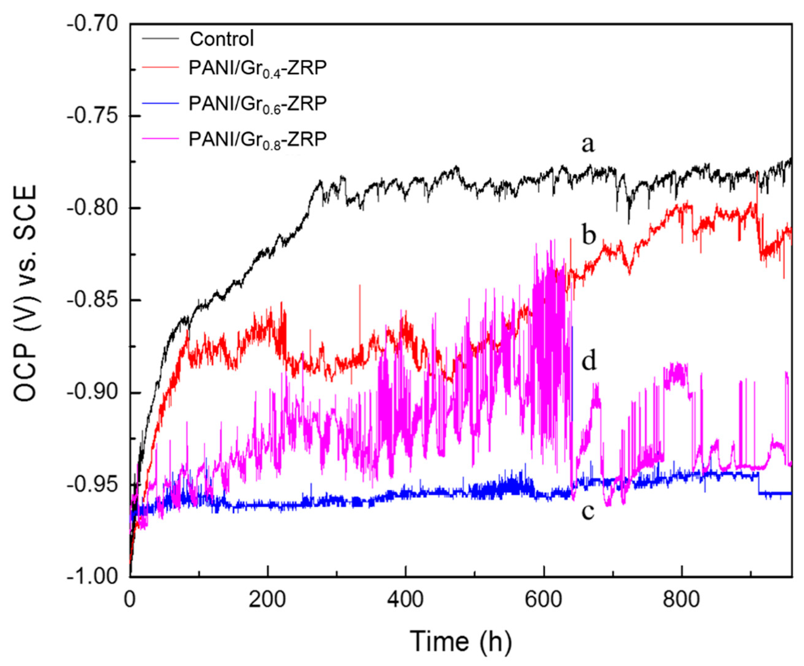
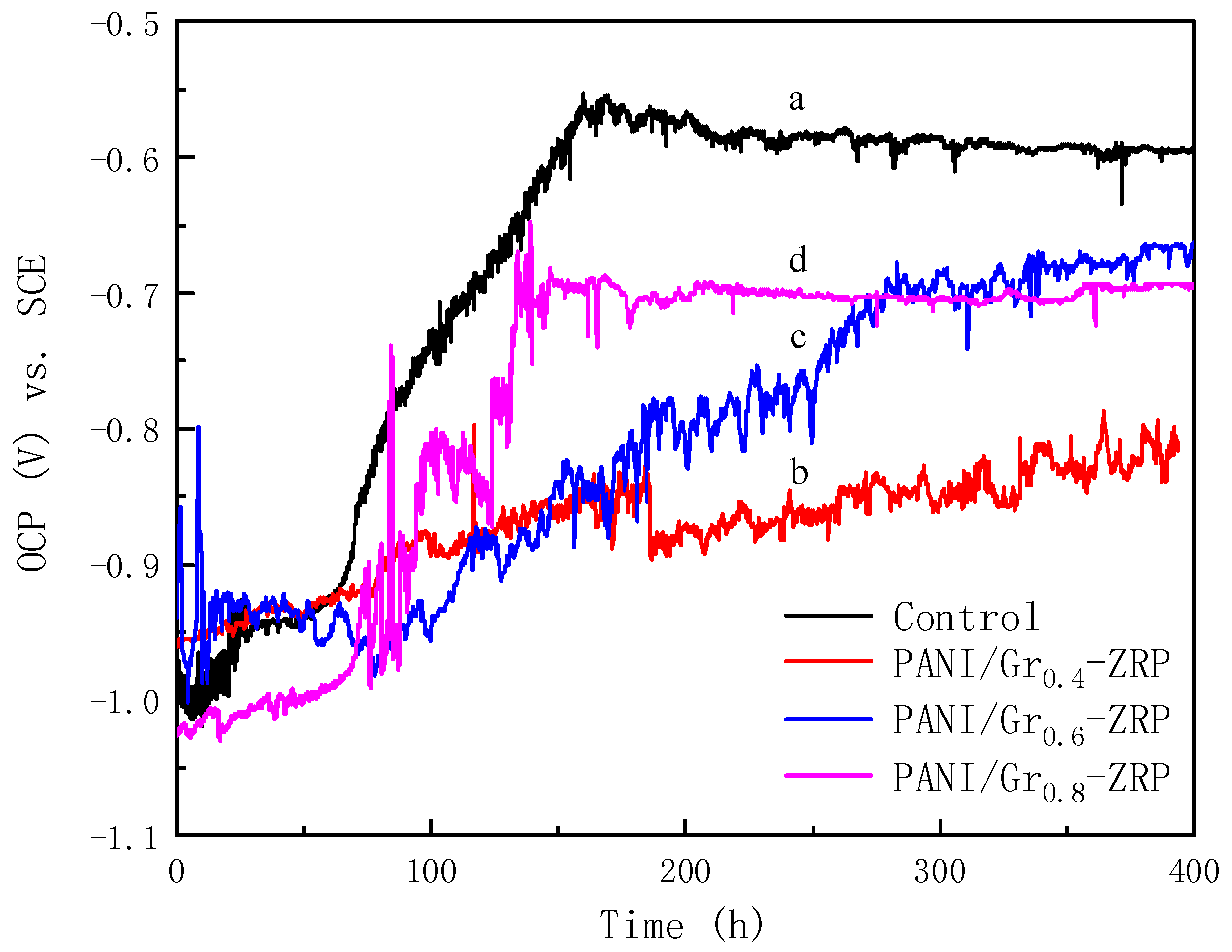
3.2. OCP Measurements
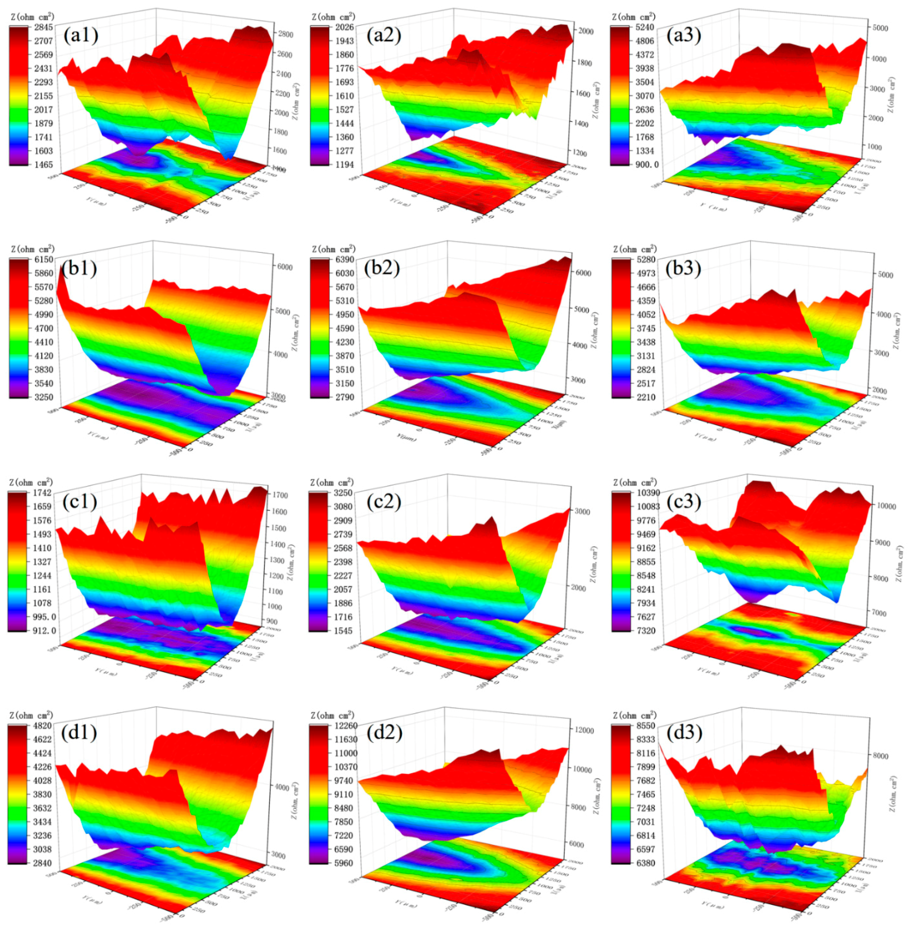
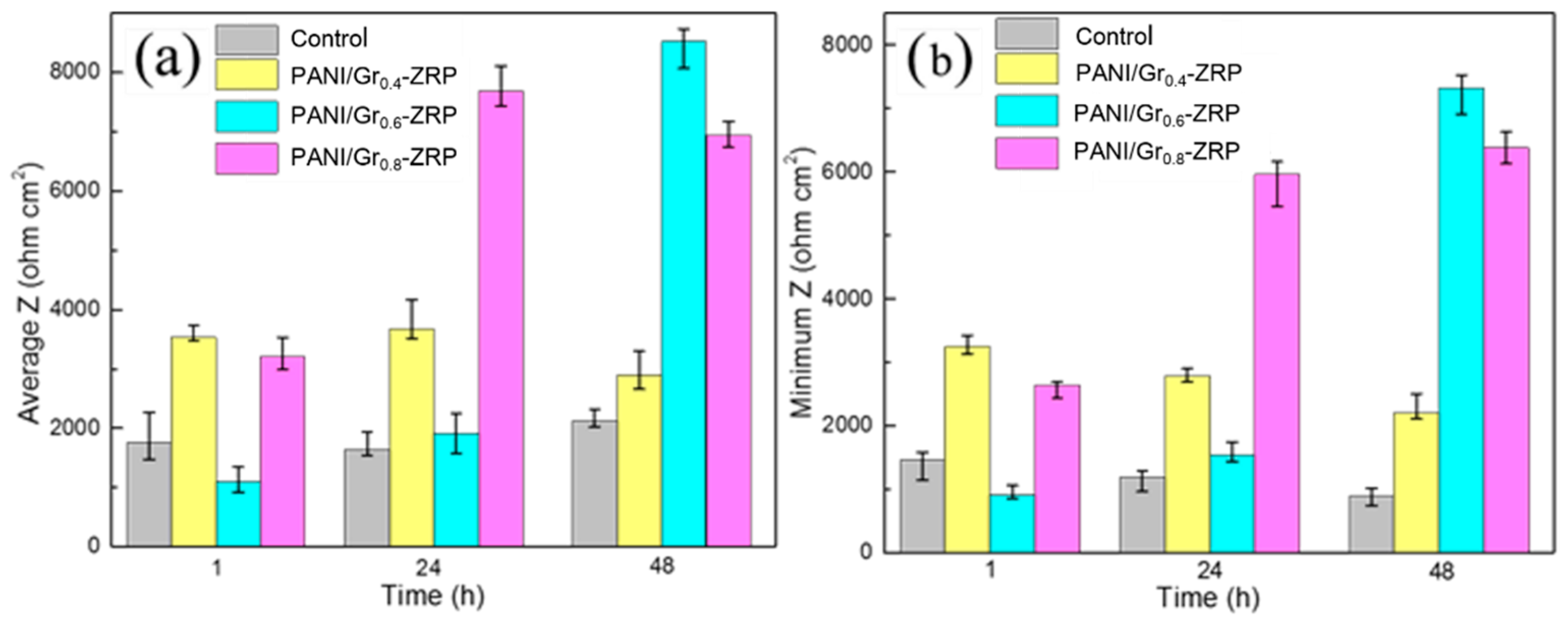
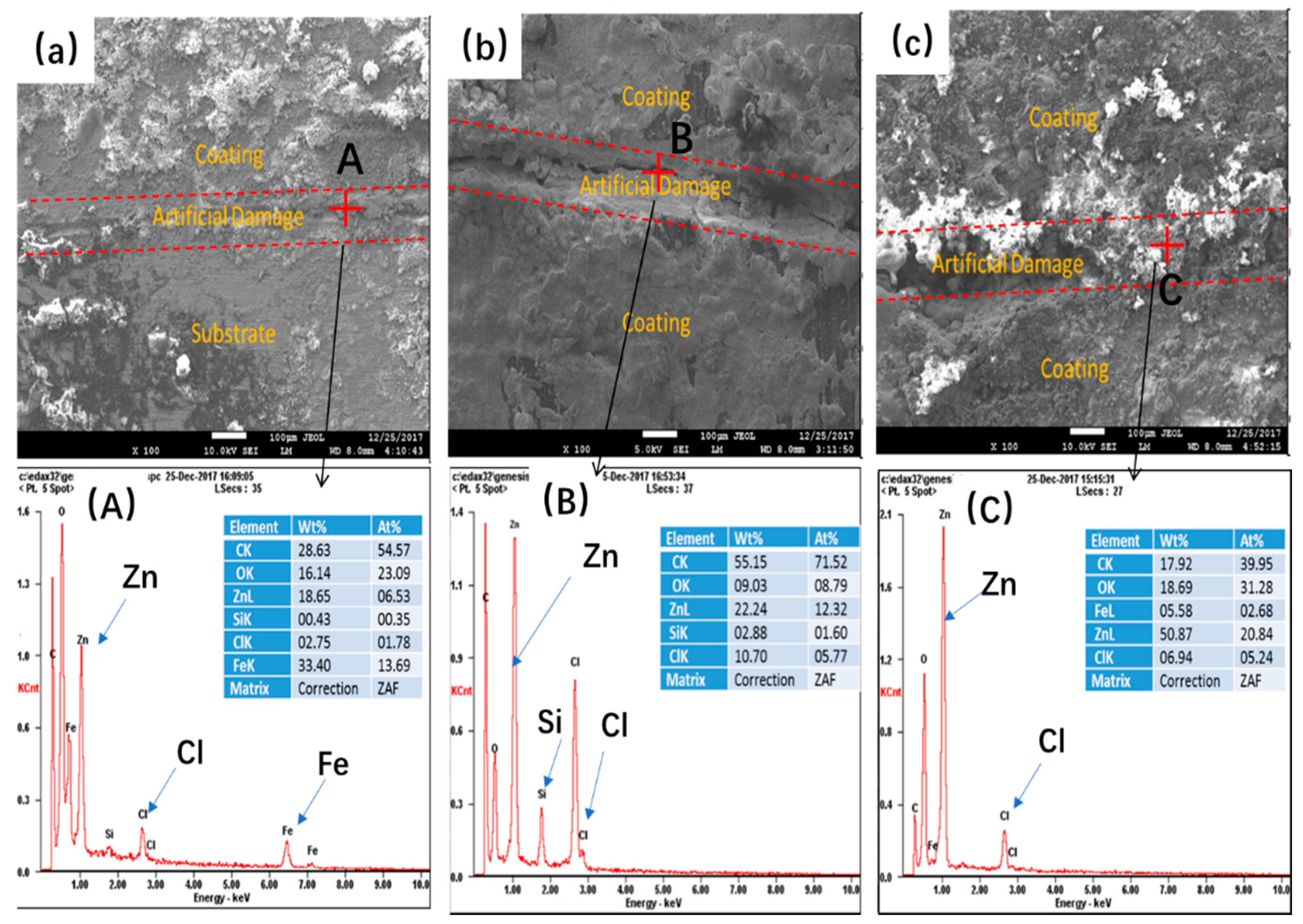
3.3. LEIS Measurement of the PANI/Gr-ZRP Coatings with Artificial Defect
4. Conclusions
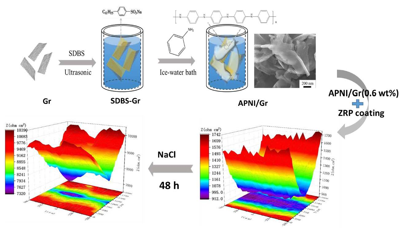
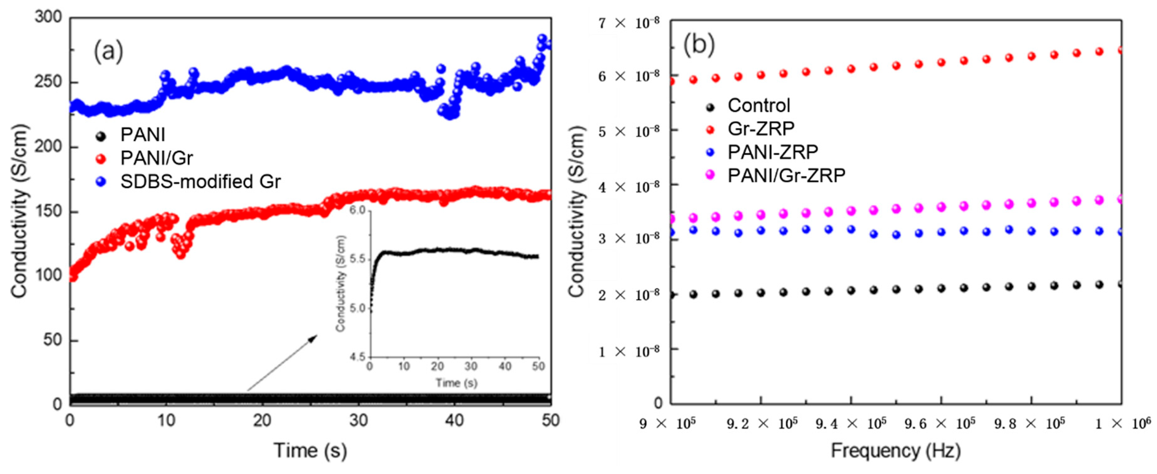
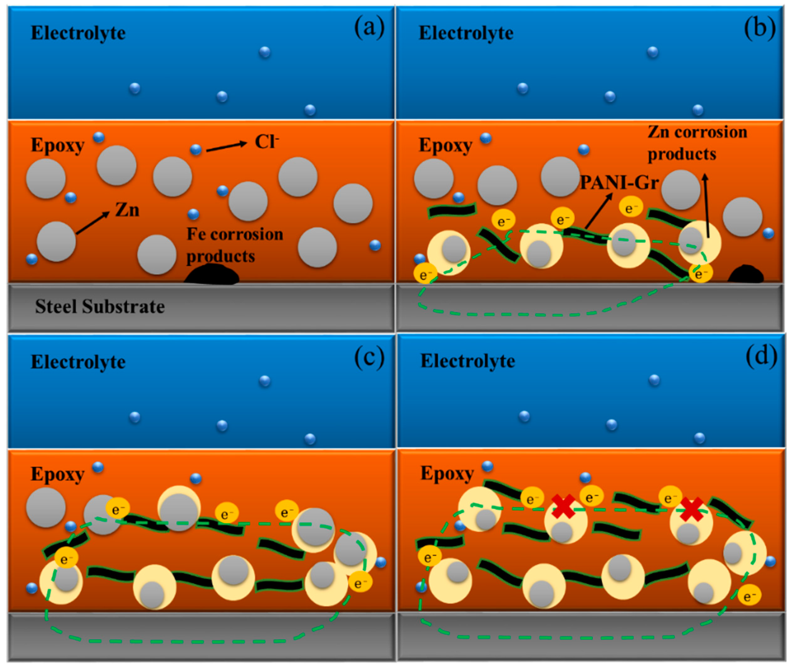
- Conductivity measurements indicate that the synthesized PANI/Gr shows higher conductivity compared to the PANI. OCP and LEIS results at the defect region indicate that the mixture of PANI/Gr in this investigation indeed enhances the sacrificially cathodic protection of the ZRP coating by the extension of its active sacrificial duration.
- Higher values of coating resistance in the EIS results for PANI/Gr-modified ZRP implicate the reduction of the coating porosity, leading to the better barrier properties of the modified ZRP. The ZRP mixed with the PANI/Gr at a content of 0.6% exhibits the best synergetic enhancement of the coating physical barrier as well as enhanced zinc sacrificial cathodic protection across the range of investigated PANI/Gr mixtures.
Author Contributions
Funding
Conflicts of Interest
References
- Akbarinezhad, E.; Ebrahimi, M.; Sharif, F.; Ghanbarzadeh, A. Evaluating protection performance of zinc rich epoxy paints modified with polyaniline and polyaniline-clay nanocomposite. Prog. Org. Coat. 2014, 77, 1299–1308. [Google Scholar] [CrossRef]
- Kowalczyk, K.; Spycha, T. Zinc-free varnishes and zinc-rich paints modified with ionic liquids. Corros. Sci. 2014, 78, 111–120. [Google Scholar] [CrossRef]
- Schaefer, K.; Miszczyk, A. Improvement of electrochemical action of zinc-rich paints by addition of nanoparticulate zinc. Corros. Sci. 2013, 66, 380–391. [Google Scholar] [CrossRef]
- Gergely, A.; Bertóti, I.; Török, T.; Pfeifer, É.; Kálmán, E. Corrosion protection with zinc-rich epoxy paint coatings embedded with various amounts of highly dispersed polypyrrole-deposited alumina monohydrate particles. Prog. Org. Coat. 2013, 76, 17–32. [Google Scholar] [CrossRef]
- Ramezanzadeh, B.; Moghadam, M.H.M.; Shohani, N.; Mahdavian, M. Effects of highly crystalline and conductive polyaniline/graphene oxide composites on the corrosion protection performance of a zinc-rich epoxy coating. Chem. Eng. J. 2017, 320, 363–375. [Google Scholar] [CrossRef]
- Shirehjini, F.T.; Danaee, I.; Eskandari, H. Effect of nano clay on corrosion protection of Zinc-rich epoxy coatings on steel 37. J. Mater. Sci. Technol. 2016, 32, 1152–1160. [Google Scholar] [CrossRef]
- Anandhi, A.; Palraj, S.; Subramanian, G. Corrosion resistance and improved adhesion properties of propargyl alcohol impregnated mesoporous titanium dioxide built-in epoxy zinc rich primer. Prog. Org. Coat. 2016, 97, 10–18. [Google Scholar] [CrossRef]
- Hayatdavoudi, H.; Rahsepar, M. A mechanistic study of the enhanced cathodic protection performance of graphene enforced zinc rich nanocomposite coating for corrosion protection of carbon steel substrate. J. Alloys Compd. 2017, 727, 1148–1156. [Google Scholar] [CrossRef]
- Pan, T.; Yu, Q. Long-term anti-corrosion performance of a conducting polymer-based coating system for steels. J. Mater. Eng. Perform. 2016, 25, 2384–2394. [Google Scholar] [CrossRef]
- Balgude, D.; Sabnis, A.; Ghosh, S.K. Investigation of cardanol-based reactive polyamide as a crosslinker in epoxy zinc-rich primer. J. Coat. Technol. Res. 2017, 14, 583–595. [Google Scholar] [CrossRef]
- Cubides, Y.; Castaneda, H. Corrosion protection mechanisms of carbon nanotube and zinc-rich epoxy primers on carbon steel in simulated concrete pore solutions in the presence of chloride ions. Corros. Sci. 2016, 109, 145–161. [Google Scholar] [CrossRef]
- Meroufel, A.; Touzain, S. EIS characterization of new zinc-rich powder coatings. Prog. Org. Coat. 2007, 59, 197–205. [Google Scholar] [CrossRef]
- Chen, W.B.; Chen, P.; Chen, H.Y.; Wu, J.; Tsai, W.T. Development of Al-containing zinc-rich paints for corrosion resistance. Appl. Surf. Sci. 2002, 187, 154–164. [Google Scholar] [CrossRef]
- Jalili, M.; Rostami, M.; Ramezanzadeh, B. An investigation of the electrochemical action of the epoxy zinc-rich coatings containing surface modified aluminum nanoparticle. Appl. Surf. Sci. 2015, 238, 95–108. [Google Scholar] [CrossRef]
- Arman, S.Y.; Ramezanzadeh, B.; Farghadani, S.; Mehdipour, M.; Rajabi, A. Application of the electrochemical noise to investigate the corrosion resistance of an epoxy zinc-rich coating loaded with lamellar aluminum and micaceous iron oxide particles. Corros. Sci. 2013, 77, 118–127. [Google Scholar] [CrossRef]
- Gharahcheshmeh, M.H.; Sohi, M.H. Pulse electrodeposition of Zn-Co alloy coatings obtained from an alkaline bath. Mater. Chem. Phys. 2012, 134, 1146–1152. [Google Scholar] [CrossRef]
- Liu, J.; Lei, Y.; Qiu, Z.; Li, D.; Chang, X. Insight into the impact of conducting polyaniline/graphene nanosheets on corrosion mechanism of zinc-rich epoxy primers on low alloy DH32 steel in artificial sea water. J. Electrochem. Soc. 2018, 165, C878–C889. [Google Scholar] [CrossRef]
- Stejskal, J.; Gilbert, R.G. Polyaniline. Preparation of a conducting polymer (IUPAC technical report). Pure Appl. Chem. 2002, 74, 857–867. [Google Scholar] [CrossRef]
- Meroufel, A.; Deslouis, C.; Touzain, S. Electrochemical and anticorrosion performances of zinc-rich and polyaniline powder coatings. Electrochim. Acta 2008, 53, 2331–2338. [Google Scholar] [CrossRef]
- Yan, J.; Wei, T.; Shao, B.; Fan, Z.; Qian, W.; Zhang, M.; Wei, F. Preparation of a graphene nanosheet/polyaniline composite with high specific capacitance. Carbon 2010, 48, 487–493. [Google Scholar] [CrossRef]
- Xu, J.; Wang, K.; Zu, S.Z.; Han, B.H.; Wei, Z. Hierarchical nanocomposites of polyaniline nanowire arrays on graphene oxide sheets with synergistic effect for energy storage. ACS Nano 2010, 4, 5019–5026. [Google Scholar] [CrossRef]
- Furukawa, Y.; Ueda, F.; Hyodo, Y.; Harada, I.; Nakajima, T.; Kawagoe, T. Vibrational spectra and structure of polyaniline. Macromolecules 1988, 21, 1297–1305. [Google Scholar] [CrossRef]
- Trchov, M.; Sedenkov, I.; Tobolkov, E.; Stejskal, J. FTIR spectroscopic and conductivity study of the thermal degradation of polyaniline films. Polym. Degrad. Stab. 2004, 86, 179–185. [Google Scholar] [CrossRef]
- Gharahcheshmeh, M.H.; Gleason, K.K. Device fabrication based on oxidative chemical vapor deposition (oCVD) Synthesis of conducting polymers and related conjugated organic materials. Adv. Mater. Interfaces 2019, 6, 1801564. [Google Scholar] [CrossRef]
- Trchova, M.; Stejskal, J. Polyaniline: The infrared spectroscopy of conducting polymer nanotubes (IUPAC Technical Report). Pure Appl. Chem. 2011, 83, 1803–1817. [Google Scholar] [CrossRef]
- Cong, H.P.; Ren, X.C.; Wang, P.; Yu, S.H. Flexible graphene–polyaniline composite paper for high-performance supercapacitor. Energy Environ. Sci. 2013, 6, 1185–1191. [Google Scholar] [CrossRef]
- Al-Mashat, L.; Shin, K.; Kalantar-zadeh, K.; Plessis, J.D.; Han, S.H.; Kojima, R.W.; Wlodarski, W. Graphene/polyaniline nanocomposite for hydrogen sensing. J. Phys. Chem. C 2010, 114, 16168–16173. [Google Scholar] [CrossRef]
- National Association of Corrosion Engineers (NACE). NACE Standard Practice SP0169: Control of External Corrosion on Underground or Submerged Metallic Piping Systems; NACE: Houston, TX, USA, 2013. [Google Scholar]
- Ohtsuka, T. Corrosion protection of steels by conducting polymer coating. Int. J. Corros. 2012, 907, 2012. [Google Scholar] [CrossRef]
- Kowalski, D.; Ueda, M.; Ohtsuka, T. Corrosion protection of steel by bi-layered polypyrrole doped with molybdophosphate and naphthalenedisulfonate anions. Corros. Sci. 2006, 49, 1635–1644. [Google Scholar] [CrossRef]
- Mrad, M.; Amor, Y.B.; Dhouibi, L.; Montemor, F. Electrochemical study of polyaniline coating electropolymerized onto AA2024-T3 aluminium alloy: Physical properties and anticorrosion performance. Synth. Met. 2017, 234, 145–153. [Google Scholar] [CrossRef]
- Njoku, D.I.; Cui, M.M.; Xiao, H.G.; Shang, B.H.; Li, Y. Understanding the anticorrosive protective mechanisms of modified epoxy coatings with improved barrier, active and self-healing functionalities: EIS and spectroscopic techniques. Sci. Rep. 2017, 7, 15597. [Google Scholar] [CrossRef] [PubMed]
- Martins, J.I.; Reis, T.C.; Bazzaoui, M.; Bazzaoui, E.A.; Martins, L.I. The effect of pH on the pyrrole electropolymerization on iron in malate aqueous solutions. Prog. Org. Coat. 2009, 65, 62–70. [Google Scholar] [CrossRef]
- Margarit, I.C.P.; Mattos, O.R. About coatings and cathodic protection: Properties of the coatings influencing delamination and cathodic protection criteria. Electrochim. Acta 1998, 44, 363–371. [Google Scholar] [CrossRef]
- Magalhaes, A.A.O.; Margarit, I.C.P.; Mattos, O.R. Electrochemical characterization of chromate coatings on galvanized steel. Electrochim. Acta 1997, 44, 4281–4287. [Google Scholar] [CrossRef]
- Sheng, X.; Ting, Y.; Pehkonen, S. The influence of sulphate-reducing bacteria biofilm on the corrosion of stainless steel AISI 316. Corros. Sci. 2007, 49, 2159–2176. [Google Scholar] [CrossRef]
- Zamanizadeh, H.R.; Shishesaz, M.R.; Danaee, I. Investigation of the corrosion protection behavior of natural montmorillonite clay/bitumen nanocomposite coatings. Prog. Org. Coat. 2015, 78, 256–260. [Google Scholar] [CrossRef]


| Sample | Zinc (wt %) | PANI/Gr (wt %) | Thickness (μm) |
|---|---|---|---|
| PANI/Gr0-ZRPs (control) | 80 | 0 | 60 ± 3.4 |
| PANI/Gr0.4-ZRPs | 80 | 0.4 | 60 ± 2.7 |
| PANI/Gr0.6-ZRPs | 80 | 0.6 | 60 ± 5.3 |
| PANI/Gr0.8-ZRPs | 80 | 0.8 | 60 ± 4.6 |
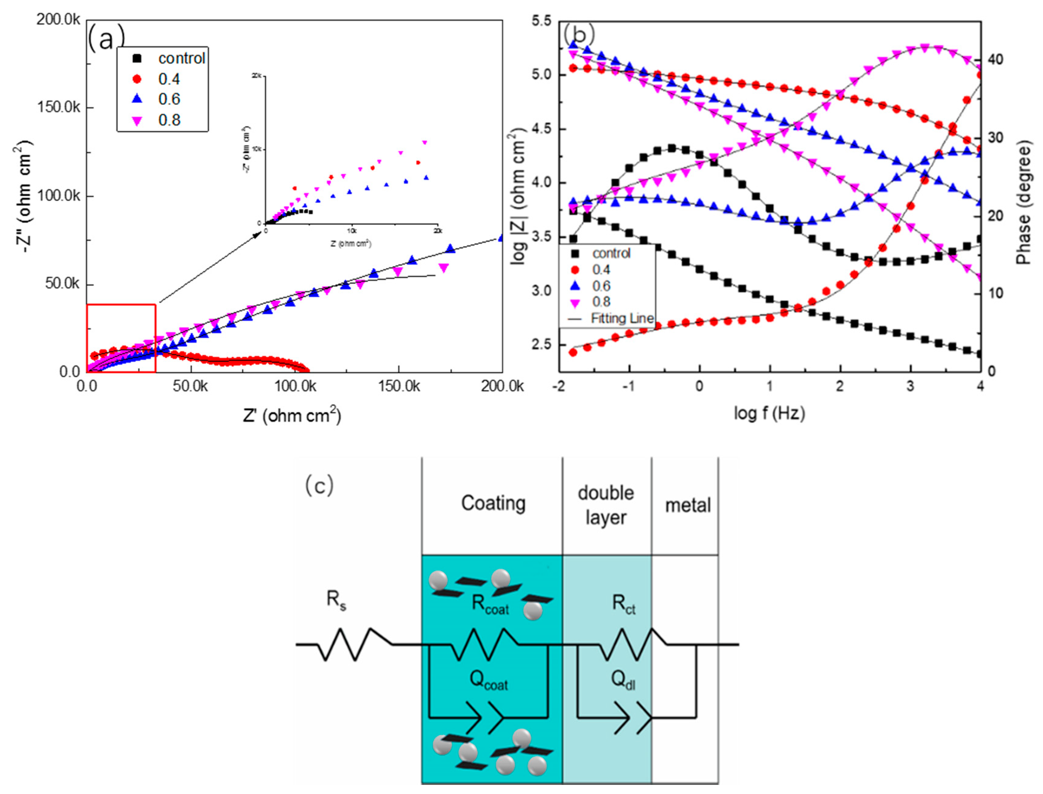
| Sample | Rs (Ω·cm2) | Ccoat (Ω−1·cm−2·sn) | Rcoat (Ω·cm2) | Cdl (Ω−1·cm−2·sn) | Rct (Ω·cm2) |
|---|---|---|---|---|---|
| PANI/Gr0-ZRPs | 0.253 | 1.36 × 10⁻⁴ | 653 | 3.12 × 10⁻⁴ | 7790 |
| PANI/Gr0.4-ZRPs | 0.575 | 8.38 × 10⁻⁴ | 7030 | 7.38 × 10⁻⁴ | 5960 |
| PANI/Gr0.6-ZRPs | 0.842 | 4.85 × 10⁻⁵ | 79200 | 9.64 × 10⁻⁴ | 2280 |
| PANI/Gr0.8-ZRPs | 0.734 | 1.13 × 10⁻³ | 31400 | 4.37 × 10⁻⁴ | 1820 |
© 2019 by the authors. Licensee MDPI, Basel, Switzerland. This article is an open access article distributed under the terms and conditions of the Creative Commons Attribution (CC BY) license (http://creativecommons.org/licenses/by/4.0/).
Share and Cite
Lei, Y.; Qiu, Z.; Liu, J.; Li, D.; Tan, N.; Liu, T.; Zhang, Y.; Chang, X.; Gu, Y.; Yin, Y. Effect of Conducting Polyaniline/Graphene Nanosheet Content on the Corrosion Behavior of Zinc-Rich Epoxy Primers in 3.5% NaCl Solution. Polymers 2019, 11, 850. https://doi.org/10.3390/polym11050850
Lei Y, Qiu Z, Liu J, Li D, Tan N, Liu T, Zhang Y, Chang X, Gu Y, Yin Y. Effect of Conducting Polyaniline/Graphene Nanosheet Content on the Corrosion Behavior of Zinc-Rich Epoxy Primers in 3.5% NaCl Solution. Polymers. 2019; 11(5):850. https://doi.org/10.3390/polym11050850
Chicago/Turabian StyleLei, Yanhua, Zhichao Qiu, Jiurong Liu, Dongdong Li, Ning Tan, Tao Liu, Yuliang Zhang, Xueting Chang, Yanhong Gu, and Yansheng Yin. 2019. "Effect of Conducting Polyaniline/Graphene Nanosheet Content on the Corrosion Behavior of Zinc-Rich Epoxy Primers in 3.5% NaCl Solution" Polymers 11, no. 5: 850. https://doi.org/10.3390/polym11050850
APA StyleLei, Y., Qiu, Z., Liu, J., Li, D., Tan, N., Liu, T., Zhang, Y., Chang, X., Gu, Y., & Yin, Y. (2019). Effect of Conducting Polyaniline/Graphene Nanosheet Content on the Corrosion Behavior of Zinc-Rich Epoxy Primers in 3.5% NaCl Solution. Polymers, 11(5), 850. https://doi.org/10.3390/polym11050850