Shortening Stabilization Time Using Pressurized Air Flow in Manufacturing Mesophase Pitch-Based Carbon Fiber


Abstract
:
1. Introduction
2. Materials and Methods
2.1. Material
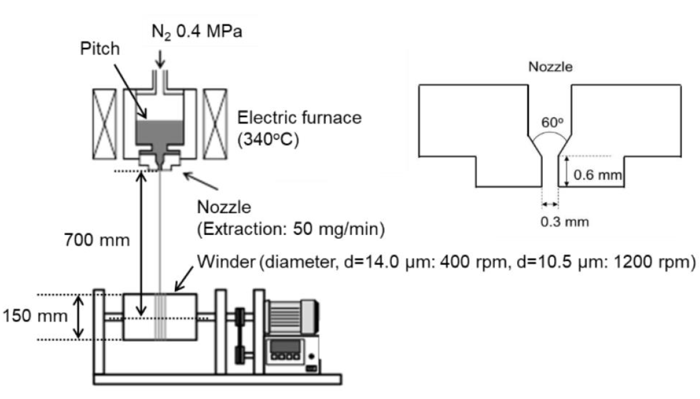
2.2. Spinning of Mesophase Pitch
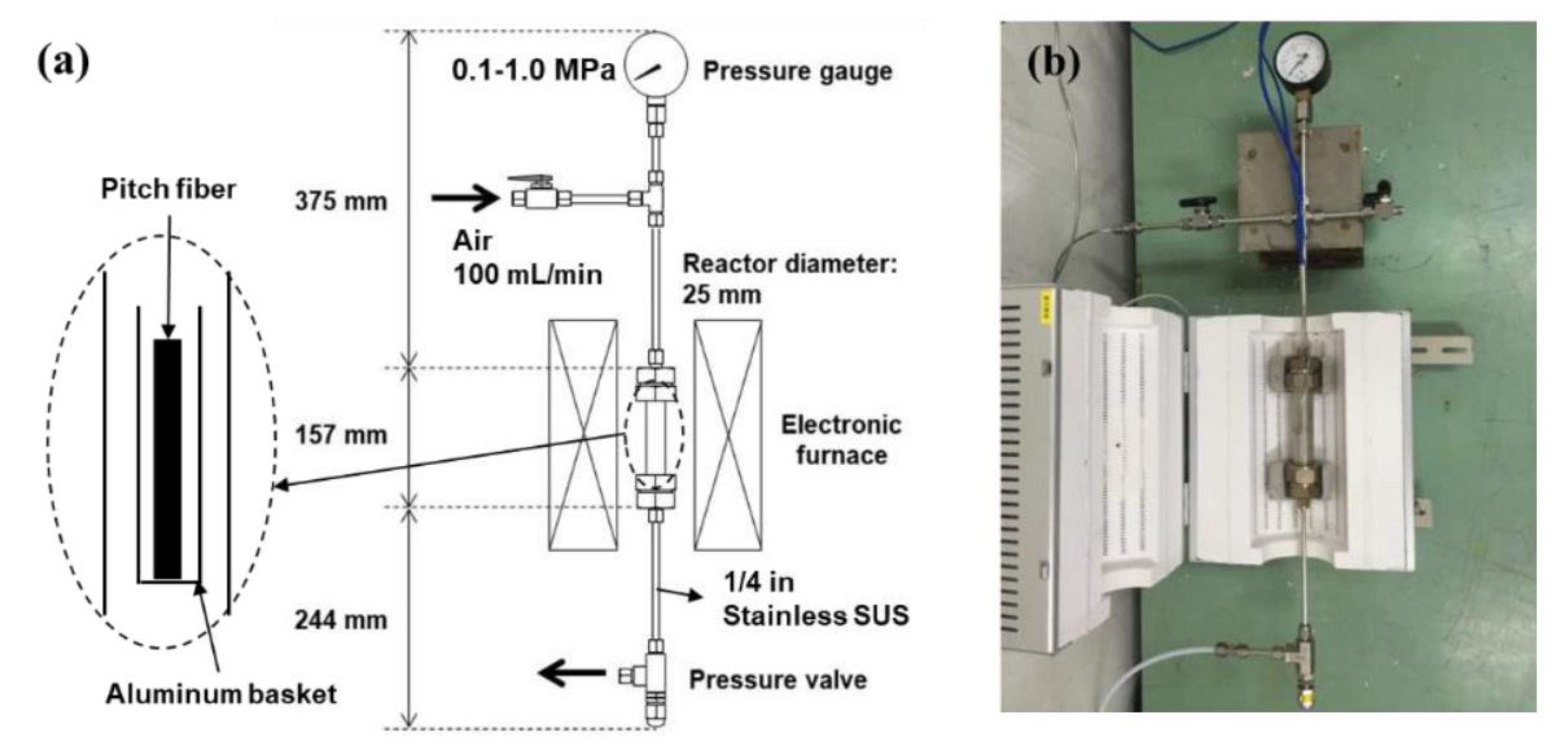
2.3. Oxidation–Stabilization of Spun Mesophase Fibers
2.4. Carbonization and Graphitization of Stabilized Fiber
2.5. Characterisation
3. Results and Discussion
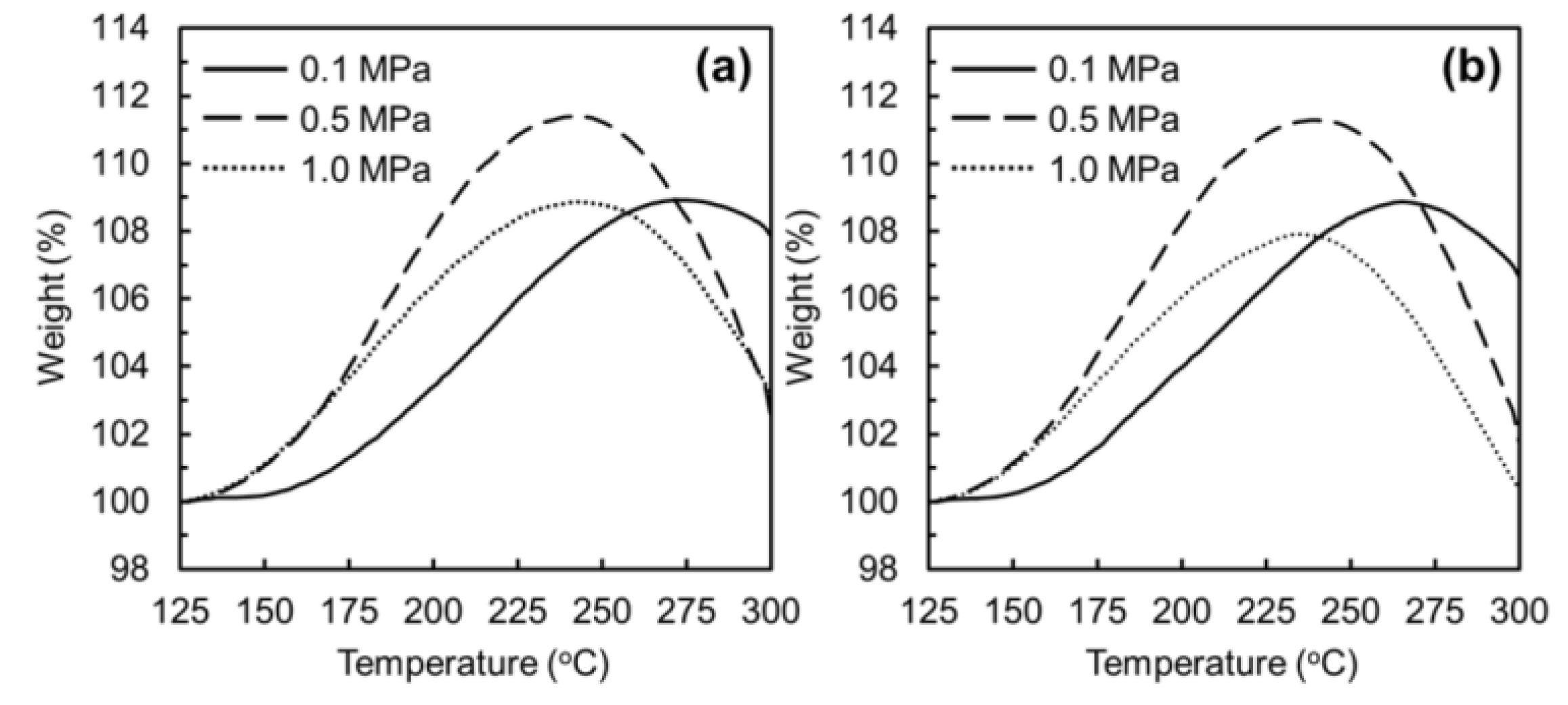
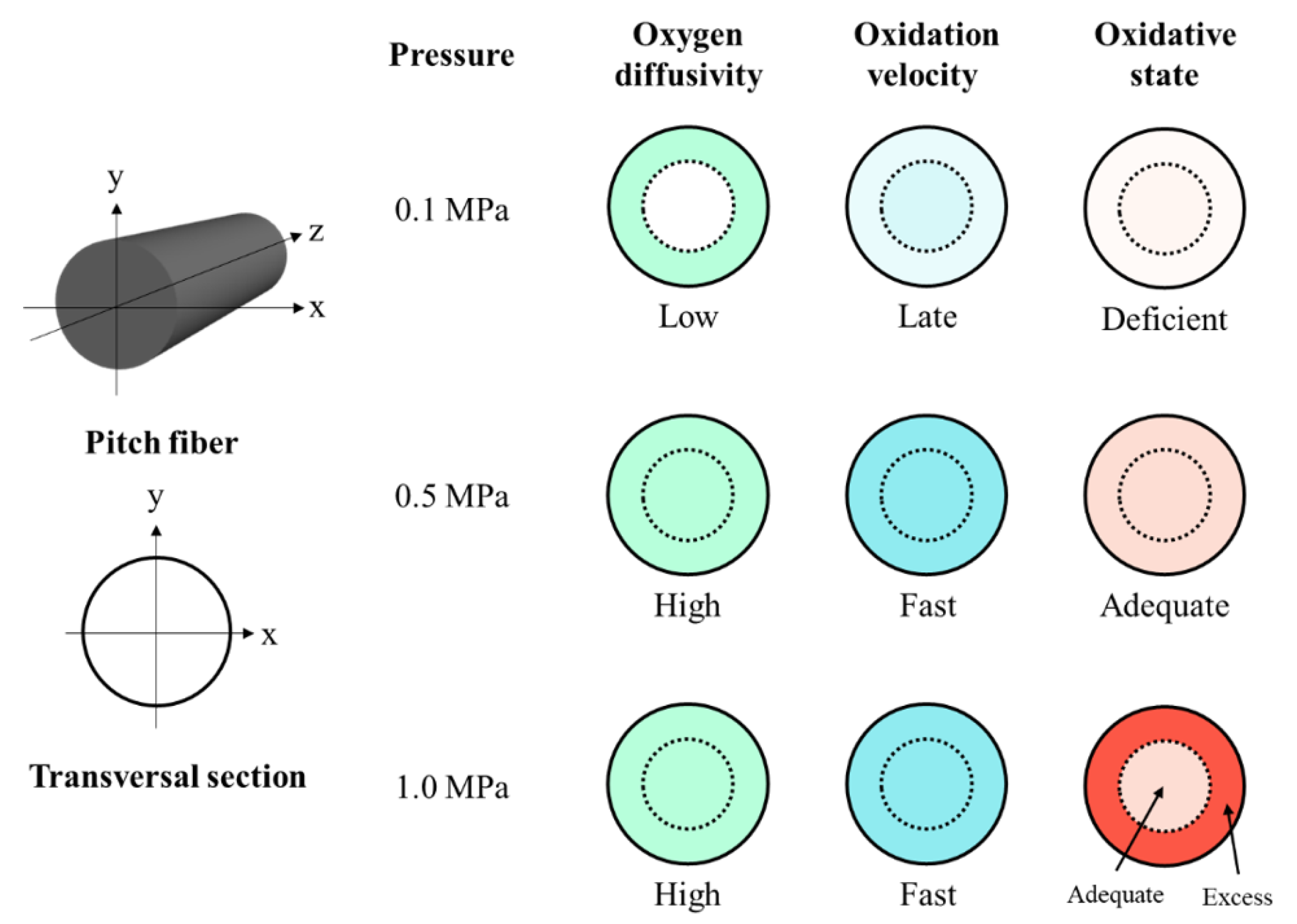
3.1. Stabilization of Mesophase Pitch Fibers under Atmospheric and Pressurised Conditions
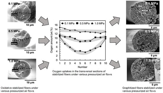
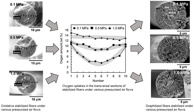
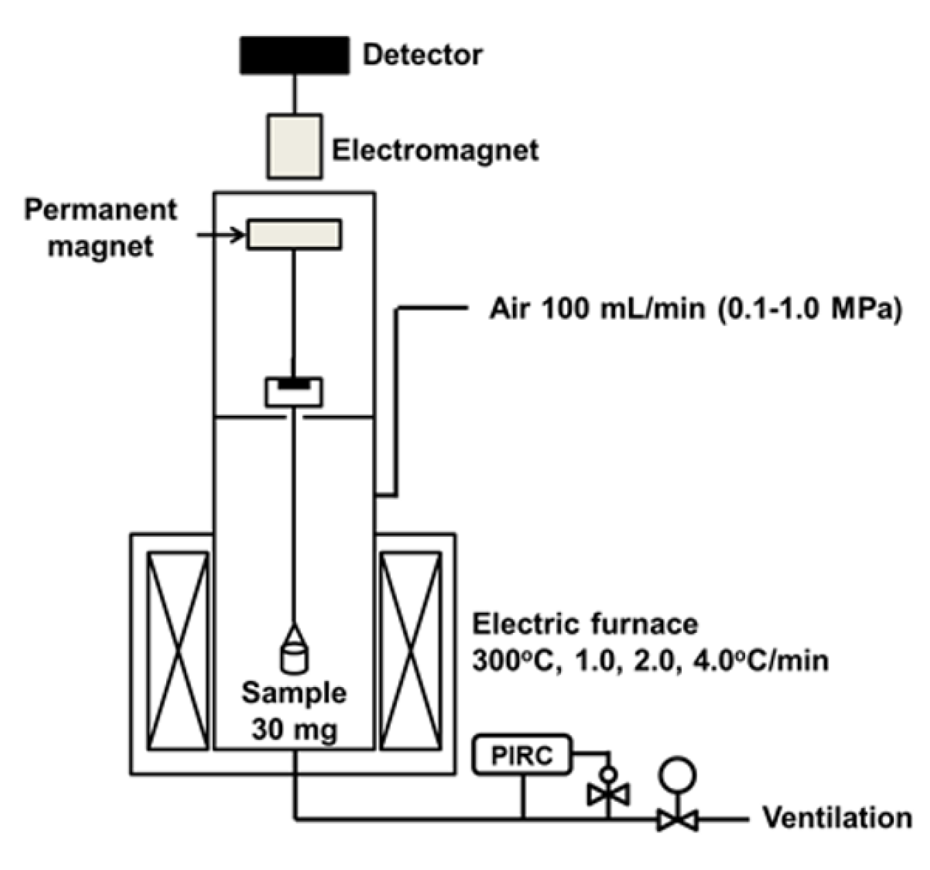
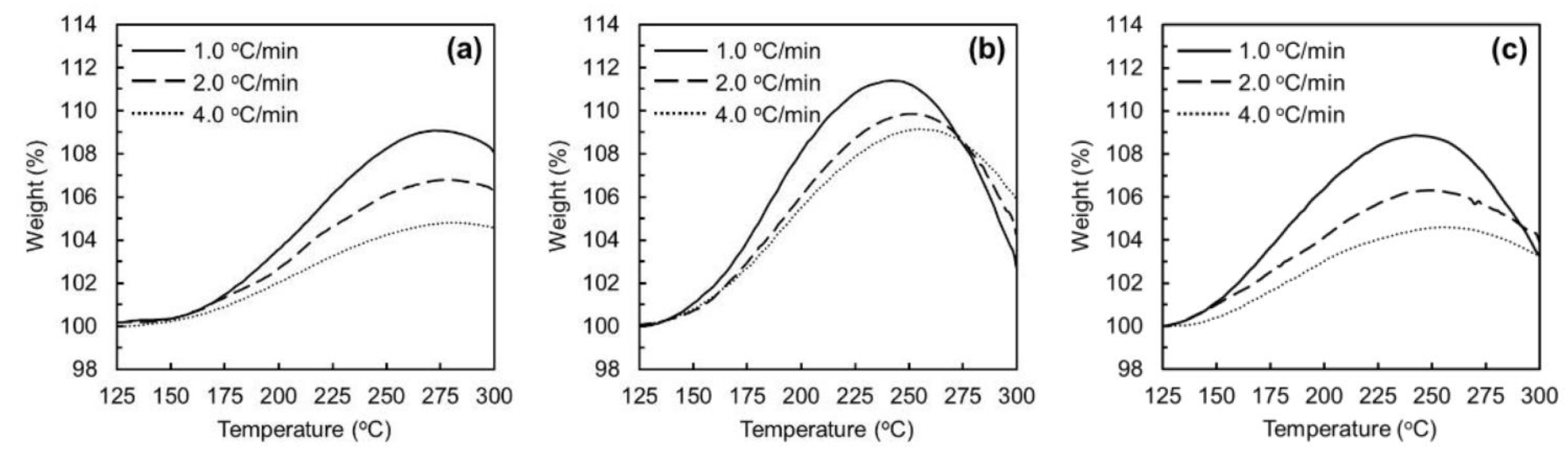
3.2. Oxidation–Stabilization of Mesophase Pitch Fiber Using Laboratory Stabilization Apparatus
3.3. Yields of Carbonization and Graphitization of the Stabilized Fibers and the Mechanical Performances of the Carbonized and Graphitized Fibers
4. Conclusions
Author Contributions
Funding
Conflicts of Interest
Appendix A

| Pitch | Softening Point*1 (°C) | Elemental Analysis | 13C-NMR | Raman Spectroscopy | XRD*3 | ||||
|---|---|---|---|---|---|---|---|---|---|
| C | H | N | Odiff. | Fa | Id/Ig*2 | d002 | Lc (002) | ||
| (wt. %) | (Å) | (nm) | |||||||
| ARMP | 240 | 94.60 | 4.89 | 0.25 | 0.26 | 0.84 | 0.65 | 3.57 | 5.23 |
| Stabilization Condition of Mesophase Pitch Fiber (ARMP-F10) | Yield and Mechanical Properties of Carbonized Fiber (ARMP-CF10)*3 | |||||||||
|---|---|---|---|---|---|---|---|---|---|---|
| Applied Pressure | Heating Rate | Soaking Temperature | Soaking Time | Oxygen Uptake*1 | Total Time*2 | Yield | Diameter | Tensile Strength | Elongation Ratio | Young’s Modulus |
| (MPa) | (°C/min) | (°C) | (min) | (wt. %) | (min) | (wt. %) | (μm) | (GPa) | (%) | (GPa) |
| 0.1 | 2.0 | 250 | 0 | 5.2 | 50 | 81.0 | 7.6 ± 0.4 | 1.0 ± 0.6 | 0.9 | 105 ± 71 |
| 260 | 0 | 6.2 | 55 | 85.2 | 7.8 ± 0.2 | 2.4 ± 0.3 | 1.0 | 105 ± 32 | ||
| 3.0 | 270 | 0 | 6.5 | 40 | 83.2 | 7.7 ± 0.1 | 2.4 ± 0.3 | 1.5 | 160 ± 30 | |
| 270 | 30 | 7.8 | 90 | 85.6 | 7.6 ± 0.2 | 2.1 ± 0.3 | 1.6 | 141 ± 41 | ||
| 0.5 | 270 | 0 | 11.7 | 300 | 88.3 | 7.7 ± 0.1 | 2.9 ± 0.4 | 1.7 | 171 ± 29 | |
| 0.5 | 2.0 | 250 | 0 | 6.3 | 50 | 90.0 | 7.6 ± 0.1 | 3.0 ± 0.3 | 1.6 | 180 ± 26 |
| 260 | 0 | 11.4 | 55 | 90.9 | 7.7 ± 0.1 | 3.4 ± 0.2 | 1.7 | 177 ± 21 | ||
| 3.0 | 260 | 15 | 11.1 | 48 | 88.8 | 7.6 ± 0.2 | 2.8 ± 0.5 | 1.7 | 166 ± 30 | |
| 270 | 0 | 10.8 | 40 | 89.0 | 7.7 ± 0.1 | 3.3 ± 0.3 | 1.8 | 154 ± 54 | ||
| 1.0 | 2.0 | 250 | 0 | 7.0 | 50 | 85.3 | 7.8 ± 0.2 | 2.3 ± 0.3 | 1.4 | 169 ± 22 |
| 260 | 0 | 11.5 | 55 | 85.4 | 7.7 ± 0.2 | 2.4 ± 0.3 | 1.4 | 165 ± 40 | ||
| 3.0 | 260 | 0 | 11.5 | 33 | 89.6 | 7.7 ± 0.2 | 2.3 ± 0.4 | 1.7 | 185 ± 20 | |
| 270 | 0 | 11.2 | 40 | 85.2 | 7.7 ± 0.2 | 2.6 ± 0.5 | 1.5 | 154 ± 55 | ||
| Stabilization Condition of Mesophase Pitch Fiber (ARMP-F10) | Yield and Mechanical Properties of Graphitized Fiber (ARMP-GF10)*1 | |||||||
|---|---|---|---|---|---|---|---|---|
| Applied Pressure | Heating Rate | Soaking Temperature | Soaking Time | Yield | Diameter | Tensile Strength | Elongation Ratio | Young′s Modulus |
| (MPa) | (°C/min) | (°C) | (min) | (wt. %) | (μm) | (GPa) | (%) | (GPa) |
| 0.1 | 2.0 | 250 | 0 | - | - | - | - | - |
| 260 | 0 | 83.0 | 7.6 ± 0.1 | 3.1 ± 0.2 | 0.5 | 617 ± 44 | ||
| 3.0 | 270 | 0 | 82.7 | 7.5 ± 0.1 | 3.4 ± 0.3 | 0.5 | 599 ± 31 | |
| 270 | 30 | 84.7 | 7.4 ± 0.1 | 3.7 ± 0.3 | 0.6 | 612 ± 24 | ||
| 0.5 | 270 | 0 | 87.1 | 7.4 ± 0.1 | 4.0 ± 0.3 | 0.6 | 663 ± 47 | |
| 0.5 | 2.0 | 250 | 0 | 87.1 | 7.5 ± 0.1 | 4.1 ± 0.2 | 0.6 | 671 ± 39 |
| 260 | 0 | 87.3 | 7.5 ± 0.1 | 4.6 ± 0.2 | 0.6 | 765 ± 42 | ||
| 3.0 | 260 | 15 | 87.0 | 7.4 ± 0.2 | 4.2 ± 0.4 | 0.6 | 699 ± 55 | |
| 270 | 0 | 87.0 | 7.5 ± 0.1 | 4.5 ± 0.3 | 0.6 | 765 ± 42 | ||
| 1.0 | 2.0 | 250 | 0 | 84.9 | 7.5 ± 0.1 | 3.3 ± 0.4 | 0.5 | 660 ± 49 |
| 260 | 0 | 82.8 | 7.6 ± 0.1 | 3.1 ± 0.4 | 0.5 | 615 ± 90 | ||
| 3.0 | 260 | 0 | 87.1 | 7.5 ± 0.1 | 3.4 ± 0.2 | 0.6 | 733 ± 24 | |
| 270 | 0 | 83.0 | 7.5 ± 0.1 | 3.5 ± 0.4 | 0.5 | 702 ± 51 | ||

References
- Yang, K.S.; Kim, B.H.; Yoon, S.H. Pitch based carbon fibers for automotive body and electrodes. Carbon Lett. 2014, 15, 162–170. [Google Scholar] [CrossRef]
- Frank, E.; Steudle, L.M.; Ingildeev, D.; Spörl, J.M.; Buchmeiser, M.R. Carbon fibers: Precursor systems, processing, structure, and properties. Angew. Chem. Int. Ed. 2014, 53, 5262–5298. [Google Scholar] [CrossRef]
- Chand, S. Review carbon fibers for composites. J. Mater. Sci. 2000, 35, 1303–1313. [Google Scholar] [CrossRef]
- Huang, X. Fabrication and properties of carbon fibers. Materials 2009, 2, 2369–2403. [Google Scholar] [CrossRef]
- Kureha Chemical Co Ltd. Product Catalogue for Carbon Fiber KRECA; Kureha Chemical Co Ltd.: Tokyo, Japan, 2015. [Google Scholar]
- Alcañiz-Monge, J.; Cazorla-Amorós, D.; Linares-Solano, A.; Oya, A.; Sakamoto, A.; Hosm, K. Preparation of general purpose carbon fibers from coal tar pitches with low softening point. Carbon 1997, 35, 1079–1087. [Google Scholar] [CrossRef]
- Kadla, J.F.; Kubo, S.; Venditti, R.A.; Gilbert, R.D.; Compere, A.L.; Griffith, W. Lignin-based carbon fibers for composite fiber applications. Carbon 2002, 40, 2913–2920. [Google Scholar] [CrossRef]
- Baker, D.A.; Rials, T.G. Recent advances in low-cost carbon fiber manufacture from lignin. J. Appl. Polym. Sci. 2013, 130, 713–728. [Google Scholar] [CrossRef]
- Braun, J.L.; Holtman, K.M.; Kadla, J.F. Lignin-based carbon fibers: Oxidative thermostabilization of kraft lignin. Carbon 2005, 43, 385–394. [Google Scholar] [CrossRef]
- Yadav, M.; Chiu, F.C. Cellulose nanocrystals reinforced κ-carrageenan based UV resistant transparent bionanocomposite films for sustainable packaging applications. Carbohydr. Polym. 2019, 211, 181–194. [Google Scholar] [CrossRef]
- Kim, J.; Im, U.S.; Lee, B.; Peck, D.H.; Yoon, S.H.; Jung, D.H. Pitch-based carbon fibers from coal tar or petroleum residue under the same processing condition. Carbon Lett. 2016, 19, 72–78. [Google Scholar] [CrossRef]
- Mora, E.; Blanco, C.; Prada, V.; Santamaría, R.; Granda, M.; Menéndez, R. A study of pitch-based precursors for general purpose carbon fibres. Carbon 2002, 40, 2719–2725. [Google Scholar] [CrossRef]
- Yang, J.; Nakabayashi, K.; Miyawaki, J.; Yoon, S.H. Preparation of pitch based carbon fibers using hyper-coal as a raw material. Carbon 2016, 106, 28–36. [Google Scholar] [CrossRef]
- Yang, J.; Nakabayashi, K.; Miyawaki, J.; Yoon, S.H. Preparation of isotropic spinnable pitch and carbon fiber by the bromination–dehydrobromination of biotar and ethylene bottom oil mixture. J. Mater. Sci. 2017, 52, 1165–1171. [Google Scholar] [CrossRef]
- Kim, B.J.; Eom, Y.; Kato, O.; Miyawaki, J.; Kim, B.C.; Mochida, I.; Yoon, S.H. Preparation of carbon fibers with excellent mechanical properties from isotropic pitches. Carbon 2014, 77, 747–755. [Google Scholar] [CrossRef]
- Kim, B.J.; Kotegawa, T.; Eom, Y.; An, J.; Hong, I.P.; Kato, O.; Nakabayashi, K.; Miyawaki, J.; Yoon, S.H. Enhancing the tensile strength of isotropic pitch-based carbon fibers by improving the stabilization and carbonization properties of precursor pitch. Carbon 2016, 99, 649–657. [Google Scholar] [CrossRef]
- Edie, D.D. The effect of processing on the structure and properties of carbon fibers. Carbon 1998, 36, 345–362. [Google Scholar] [CrossRef]
- Frank, E.; Hermanutz, F.; Buchmeiser, M.R. Carbon fibers: Precursors, manufacturing, and properties. Macromol. Mater. Eng. 2012, 297, 493–501. [Google Scholar] [CrossRef]
- Minus, M.L.; Kumar, S. The processing, properties, and structure of carbon fibers. J. Miner. Met. Mater. Soc. 2005, 57, 52–58. [Google Scholar] [CrossRef]
- Horikiri, S.; Iseki, J.; Minobe, M. Process for Production of Carbon Fiber. U.S. Patent 4070446, 24 January 1978. [Google Scholar]
- Postema, A.R.; De Groot, H.; Pennings, A.J. Amorphous carbon fibres from linear low density polyethylene. J. Mater. Sci. 1990, 25, 4216–4222. [Google Scholar] [CrossRef]
- Yang, J.; Nakabayashi, K.; Miyawaki, J.; Yoon, S.H. Preparation of isotropic pitch-based carbon fiber using hyper coal through co-carbonation with ethylene bottom oil. J. Ind. Eng. Chem. 2016, 34, 397–404. [Google Scholar] [CrossRef]
- Hamaguchi, M.; Okuyama, N. Manufacturing process and applications of the Hypercoal. Tanso 2013, 257, 149–156. [Google Scholar] [CrossRef]
- Matsumoto, T.; Mochida, I. Oxygen distribution in oxidatively stabilized mesophase pitch fiber. Carbon 1993, 31, 143–147. [Google Scholar] [CrossRef]
- Mochida, I.; Toshima, H.; Korai, Y.; Hino, T. Oxygen distribution in the mesophase pitch fibre after oxidative stabilization. J. Mater. Sci. 1989, 24, 389–394. [Google Scholar] [CrossRef]
- Yoon, S.H.; Korai, Y.; Mochida, I. Assessment and optimization of the stabilization process of mesophase pitch fibers by thermal analyses. Carbon 1994, 32, 281–287. [Google Scholar] [CrossRef]
- Mochida, I.; Yoon, S.H.; Takano, N.; Fortin, F.; Korai, Y.; Yokokawa, K. Microstructure of mesophase pitch-based carbon fiber and its control. Carbon 1996, 34, 941–956. [Google Scholar] [CrossRef]
- Mochida, I.; Korai, Y.; Ku, C.H.; Watanabe, F.; Sakai, Y. Chemistry of synthesis, structure, preparation and application of aromatic-derived mesophase pitch. Carbon 2000, 38, 305–328. [Google Scholar] [CrossRef]
- Yang, H.; Yoon, S.H.; Korai, Y.; Mochida, I.; Kato, O. Microvoids present in anisotropic mesophase pitch, their as-spun and annealed fibers. Chem. Lett. 2003, 32, 168–169. [Google Scholar] [CrossRef]
- Fathollahi, B.; Jones, B.; Chau, P.C.; White, J.L. Injection and stabilization of mesophase pitch in the fabrication of carbon–carbon composites. Part III: Mesophase stabilization at low temperatures and elevated oxidation pressures. Carbon 2005, 43, 143–151. [Google Scholar] [CrossRef]
- Cornec, L.P.; Rogers, D.K.; Fain, C.C.; Edie, D.D. A Novel Stabilization Technique and Its Influence upon Carbonization Yield; Extended Abstracts, CARBON’92; Deutsche Keramische Gesellschaft: Essen, Germany, 1992; pp. 710–712. [Google Scholar]
- Liedtke, V.; Hüttinger, K.J. Mesophase pitches as matrix precursor of carbon fiber reinforced carbon: II. Stabilization of mesophase pitch matrix by oxygen treatment. Carbon 1996, 34, 1067–1079. [Google Scholar] [CrossRef]
- Tzeng, S.S.; Wang, P.L. Oxidation of a petroleum pitch under pressure. Carbon 2001, 39, 1103–1116. [Google Scholar] [CrossRef]
- Lee, S.; Eom, Y.; Kim, B.J.; Mochida, I.; Yoon, S.H.; Kim, B.C. The thermotropic liquid crystalline behavior of mesophase pitches with different chemical structures. Carbon 2015, 81, 694–701. [Google Scholar] [CrossRef]
- Mochida, I.; Shimizu, K.; Korai, Y.; Otsuka, H.; Sakai, Y.; Fujiyama, S. Preparation of mesophase pitch from aromatic hydrocarbons by the aid of HF/BF3. Carbon 1990, 28, 311–319. [Google Scholar] [CrossRef]
- Korai, Y.; Ishida, S.; Watanabe, F.; Yoon, S.H.; Wang, Y.G.; Mochida, I.; Kato, I.; Nakamura, T.; Sakai, Y.; Komatsu, M. Preparation of carbon fiber from isotropic pitch containing mesophase spheres. Carbon 1997, 35, 1733–1737. [Google Scholar] [CrossRef]
- Régnier, N.; Fontaine, S. Determination of the thermal degradation kinetic parameters of carbon fibre reinforced epoxy using TG. J. Therm. Anal. Calorim. 2001, 64, 789–799. [Google Scholar] [CrossRef]
- Blanco, C.; Lu, S.; Appleyard, S.P.; Rand, B. The stabilisation of carbon fibres studied by micro-thermal analysis. Carbon 2003, 41, 165–171. [Google Scholar] [CrossRef]
- Japanese Industrial Standards. Carbon Fiber−Determination of the Tensile Properties of the Single-Filament Specimens; JIS R 7606; International Organization for Standardization: Geneva, Switzerland, 2000. [Google Scholar]
- Drbohlav, J.; Stevenson, W.T.K. The oxidative stabilization and carbonization of a synthetic mesophase pitch, part I: The oxidative stabilization process. Carbon 1995, 33, 693–711. [Google Scholar] [CrossRef]
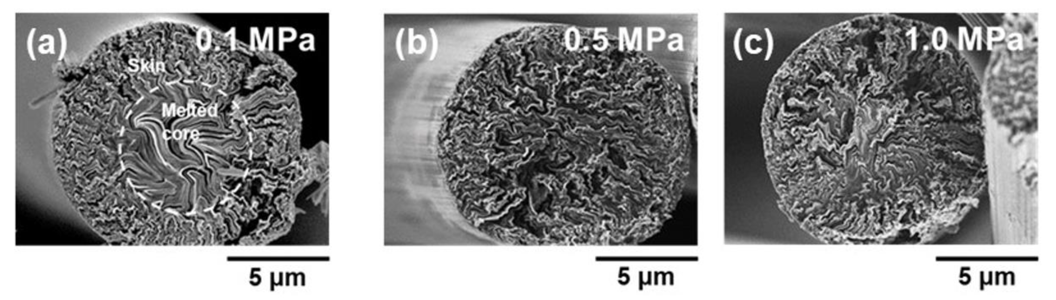
- Mochida, I.; Zeng, S.M.; Korai, Y.; Toshima, H. The introduction of a skin-core structure in mesophase pitch fibers by oxidative stabilization. Carbon 1990, 28, 193–198. [Google Scholar] [CrossRef]
- Mochida, I.; Zeng, S.M.; Korai, Y.; Hino, T.; Toshima, H. Structure and properties of mesophase pitch carbon fibre with a skin-core structure carbonized under strain. J. Mater. Sci. 1992, 27, 1960–1968. [Google Scholar] [CrossRef]


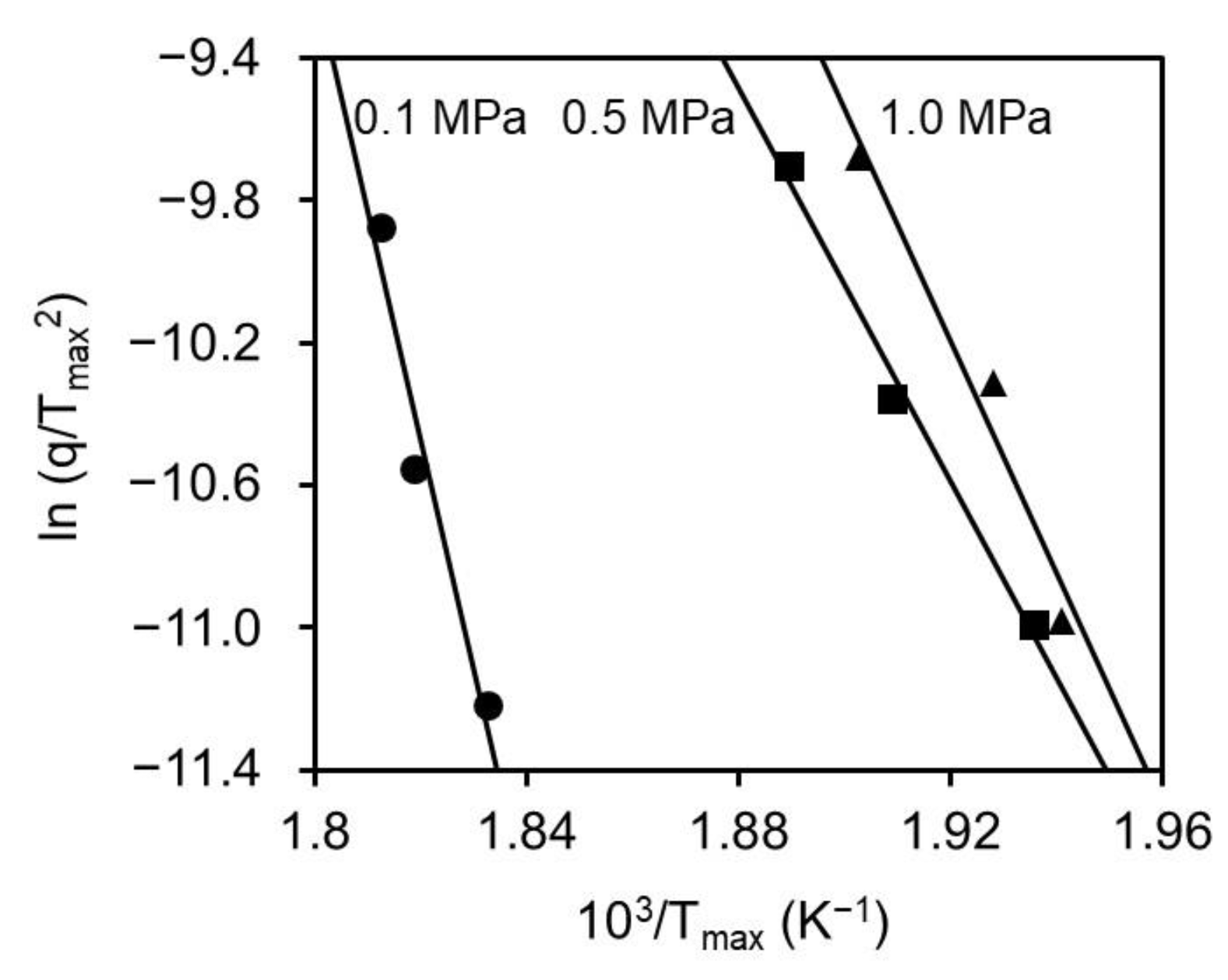
| Applied Pressure (MPa) | 0.1 | 0.5 | 1.0 |
|---|---|---|---|
| Activation Energy (kJ/mol) | 535 | 230 | 271 |
| Stabilization Condition of Mesophase Pitch Fiber (ARMP-F10) | Yield and Mechanical Properties of Carbonized Fiber (ARMP-CF10)*3 | |||||||||
|---|---|---|---|---|---|---|---|---|---|---|
| Applied Pressure | Heating Rate | Soaking Temperature | Soaking Time | Oxygen Uptake*1 | Total Time*2 | Yield | Diameter | Tensile Strength | Elongation Ratio | Young′s Modulus |
| (MPa) | (°C/min) | (°C) | (min) | (wt. %) | (min) | (wt. %) | (μm) | (GPa) | (%) | (GPa) |
| 0.1 | 2.0 | 270 | 0 | 8.5 | 60 | 83.2 | 7.8 ± 0.2 | 2.4 ± 0.3 | 1.5 | 159 ± 27 |
| 3.0 | 60 | 8.5 | 100 | 87.0 | 7.7 ± 0.2 | 2.4 ± 0.4 | 1.5 | 142 ± 34 | ||
| 0.5 | 2.0 | 270 | 0 | 11.9 | 60 | 89.1 | 7.7 ± 0.2 | 2.8 ± 0.3 | 1.8 | 186 ± 28 |
| 3.0 | 10 | 11.8 | 50 | 89.5 | 7.8 ± 0.1 | 2.4 ± 0.3 | 1.7 | 191 ± 31 | ||
| 1.0 | 2.0 | 270 | 0 | 11.2 | 60 | 85.3 | 7.5 ± 0.1 | 3.2 ± 0.3 | 1.5 | 161 ± 48 |
| 3.0 | 5 | 11.1 | 45 | 84.3 | 7.5 ± 0.3 | 2.6 ± 0.5 | 1.6 | 159 ± 39 | ||
| Stabilization Condition of Mesophase Pitch Fiber (ARMP-F10) | Yield and Mechanical Properties of Graphitized Fiber (ARMP-GF10)*1 | |||||||
|---|---|---|---|---|---|---|---|---|
| Applied Pressure | Heating Rate | Soaking Temperature | Soaking Time | Yield | Diameter | Tensile Strength | Elongation Ratio | Young’s Modulus |
| (MPa) | (°C/min) | (°C) | (min) | (wt. %) | (μm) | (GPa) | (%) | (GPa) |
| 0.1 | 2.0 | 270 | 0 | 82.4 | 7.7 ± 0.1 | 3.5 ± 0.3 | 0.6 | 508 ± 30 |
| 3.0 | 60 | 85.2 | 7.5 ± 0.1 | 3.3 ± 0.3 | 0.5 | 666 ± 50 | ||
| 0.5 | 2.0 | 270 | 0 | 86.8 | 7.6 ± 0.2 | 4.6 ± 0.3 | 0.6 | 767 ± 39 |
| 3.0 | 10 | 86.2 | 7.6 ± 0.1 | 4.4 ± 0.3 | 0.6 | 740 ± 43 | ||
| 1.0 | 2.0 | 270 | 0 | 83.0 | 7.4 ± 0.1 | 3.5 ± 0.2 | 0.5 | 725 ± 41 |
| 3.0 | 5 | 82.9 | 7.3± 0.1 | 3.9 ± 0.5 | 0.6 | 667 ± 55 | ||
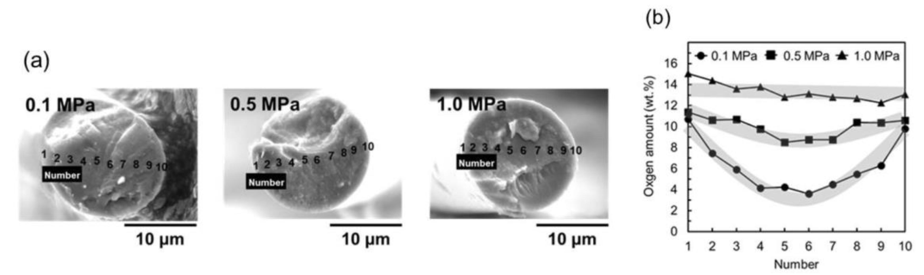
| Stabilization Conditions* | Oxygen Diffusivity From Outer Surface to Center Part of Pitch Fiber | Oxidation Reaction and Oxidized State on Molecules of Mesophase Pitch Fiber | ||||
|---|---|---|---|---|---|---|
| Applied Pressure (MPa) | Heating Rate (°C/min) | Soaking Temperature (°C ) | Soaking Time (min) | Outer Part of Fiber | Center Part of Fiber | |
| 0.1 | 2.0 | 270 | 0 | Low | Late, deficient | Late, deficient |
| 3.0 | 60 | Low | Late, excess | Late, deficient | ||
| 0.5 | 2.0 | 270 | 0 | High | Fast, adequate | Fast, adequate |
| 3.0 | 10 | High | Fast, adequate | Fast, adequate | ||
| 1.0 | 2.0 | 270 | 0 | High | Fast, excess | Fast, adequate |
| 3.0 | 5 | High | Fast, excess | Fast, excess | ||
© 2019 by the authors. Licensee MDPI, Basel, Switzerland. This article is an open access article distributed under the terms and conditions of the Creative Commons Attribution (CC BY) license (http://creativecommons.org/licenses/by/4.0/).
Share and Cite
Shimanoe, H.; Ko, S.; Jeon, Y.-P.; Nakabayashi, K.; Miyawaki, J.; Yoon, S.-H. Shortening Stabilization Time Using Pressurized Air Flow in Manufacturing Mesophase Pitch-Based Carbon Fiber. Polymers 2019, 11, 1911. https://doi.org/10.3390/polym11121911
Shimanoe H, Ko S, Jeon Y-P, Nakabayashi K, Miyawaki J, Yoon S-H. Shortening Stabilization Time Using Pressurized Air Flow in Manufacturing Mesophase Pitch-Based Carbon Fiber. Polymers. 2019; 11(12):1911. https://doi.org/10.3390/polym11121911
Chicago/Turabian StyleShimanoe, Hiroki, Seunghyun Ko, Young-Pyo Jeon, Koji Nakabayashi, Jin Miyawaki, and Seong-Ho Yoon. 2019. "Shortening Stabilization Time Using Pressurized Air Flow in Manufacturing Mesophase Pitch-Based Carbon Fiber" Polymers 11, no. 12: 1911. https://doi.org/10.3390/polym11121911
APA StyleShimanoe, H., Ko, S., Jeon, Y.-P., Nakabayashi, K., Miyawaki, J., & Yoon, S.-H. (2019). Shortening Stabilization Time Using Pressurized Air Flow in Manufacturing Mesophase Pitch-Based Carbon Fiber. Polymers, 11(12), 1911. https://doi.org/10.3390/polym11121911