Membrane Surface Patterning as a Fouling Mitigation Strategy in Liquid Filtration: A Review


 ,
,  ,
, 
 and
and 
Abstract
1. Introduction
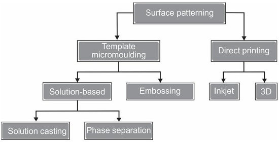
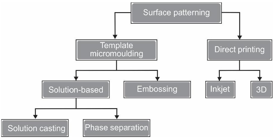
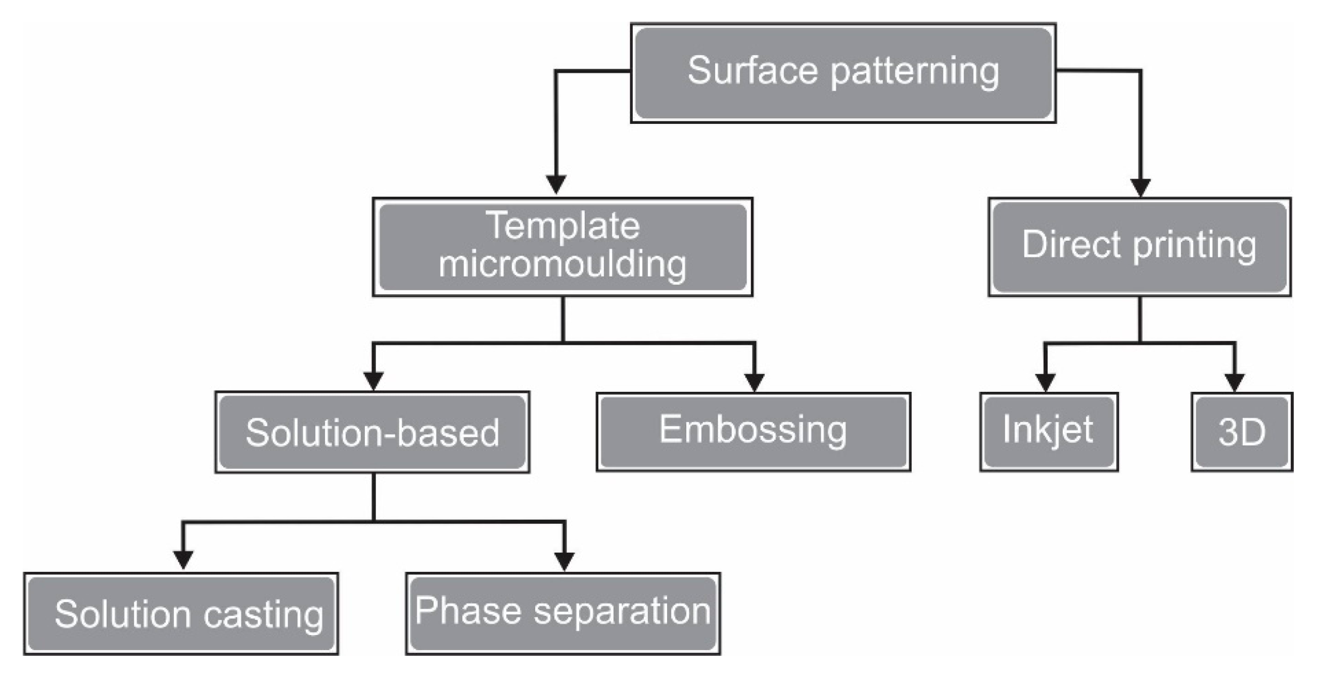
2. Membrane Surface Patterning
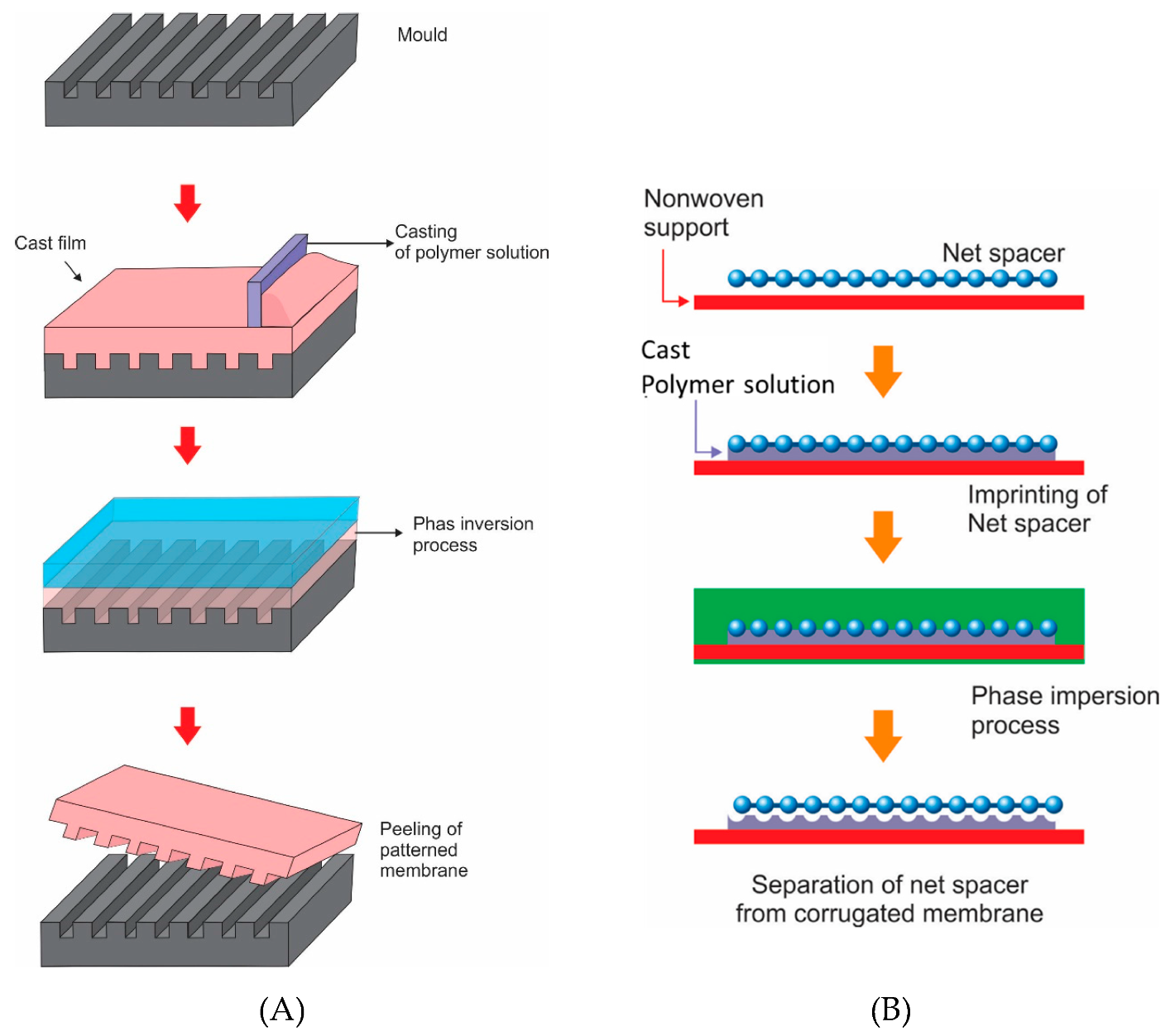
2.1. Template-Based Micromolding
2.1.1. Solution-Based Micromolding
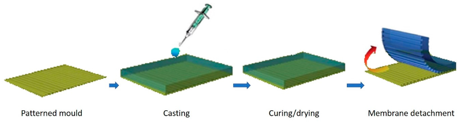
Solution Casting Micromolding
Phase Separation Micromolding
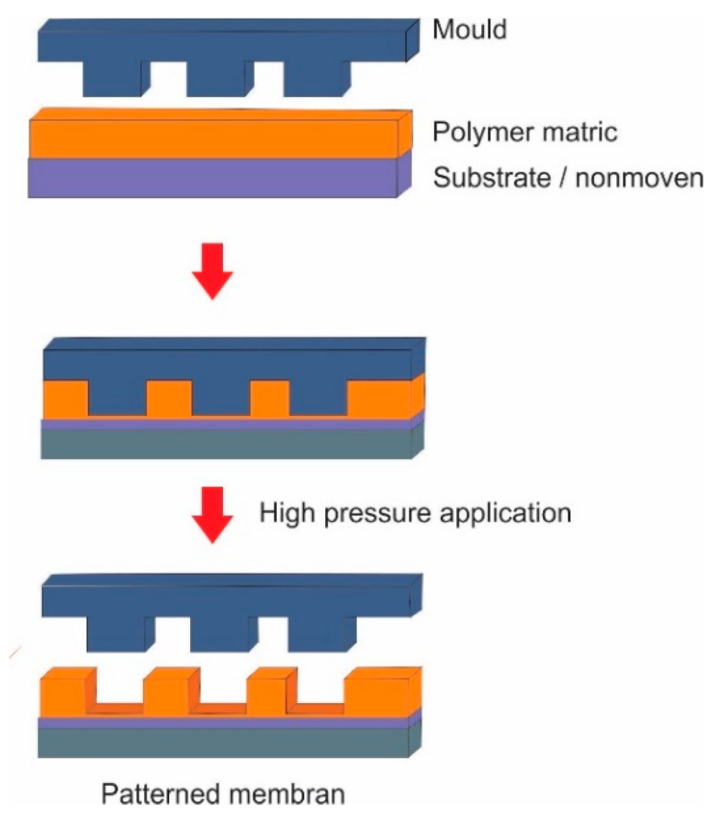
2.1.2. Embossing Micromolding
2.2. Direct Printing
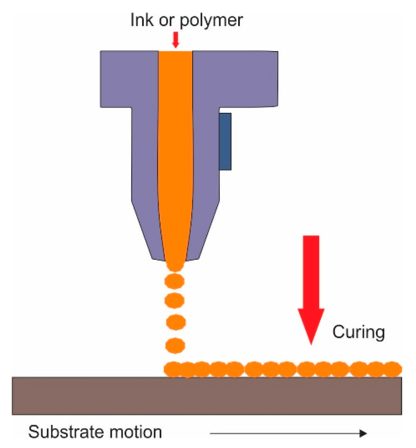
2.2.1. Inkjet Printing
2.2.2. Additive Manufacturing (3D Printing)
3. Operation Conditions of Patterned Membranes
4. Importance of Surface Patterning for Various Membrane Processes
5. Conclusions and Perspectives
Author Contributions
Funding
Conflicts of Interest
Abbreviations
| 3D | Three-dimensional |
| BSA | Bovine serum albumin |
| CLIP | Continuous liquid interface production |
| DLP | Direct light processing |
| EM | Embossing micromolding |
| NIL | Nanoimprinting lithography |
| PDMS | Polydimethylsiloxane |
| PES | Polyethersulfone |
| PRR | Permeance recovery ratio |
| PSmM | Phase separation micromolding |
| PWP | Pure water permeance |
| SCmM | Solution casting micromolding |
| SLA | Stereolithography |
| TEM | Thermal embossing micromolding |
| TFC | Thin film composite |
| VI-PSmM | Vapor-induced phase separation micromolding |
References
- Norhasyima, R.S.; Mahlia, T.M.I. Advances in CO2 utilization technology: A patent landscape review. J. CO2 Util. 2018, 26, 323–335. [Google Scholar] [CrossRef]
- Kusumo, F.; Silitonga, A.S.; Masjuki, H.H.; Ong, H.C.; Siswantoro, J.; Mahlia, T.M.I. Optimization of transesterification process for Ceiba pentandra oil: A comparative study between kernel-based extreme learning machine and artificial neural networks. Energy 2017, 134, 24–34. [Google Scholar] [CrossRef]
- Silitonga, A.S.; Masjuki, H.H.; Ong, H.C.; Sebayang, A.H.; Dharma, S.; Kusumo, F.; Siswantoro, J.; Milano, J.; Daud, K.; Mahlia, T.M.I.; et al. Evaluation of the engine performance and exhaust emissions of biodiesel-bioethanol-diesel blends using kernel-based extreme learning machine. Energy 2018, 159, 1075–1087. [Google Scholar] [CrossRef]
- Silitonga, A.S.; Mahlia, T.M.I.; Kusumo, F.; Dharma, S.; Sebayang, A.H.; Sembiring, R.W.; Shamsuddin, A.H. Intensification of Reutealis trisperma biodiesel production using infrared radiation: Simulation, optimisation and validation. Renew. Energy 2019, 133, 520–527. [Google Scholar] [CrossRef]
- Ong, H.C.; Milano, J.; Silitonga, A.S.; Hassan, M.H.; Shamsuddin, A.H.; Wang, C.Y.; Teuku, M.I.M.; Joko, S.; Fitranto, K.; Joko, S. Biodiesel production from Calophyllum inophyllum-Ceiba pentandra oil mixture: Optimization and characterization. J. Clean. Prod. 2019, 219, 183–198. [Google Scholar] [CrossRef]
- Uragami, T. Introduction to Membrane Science and Technology. In Science and Technology of Separation Membranes; John Wiley & Sons, Ltd.: Chichester, UK, 2017; pp. 1–12. ISBN 978-1-118-93255-1. [Google Scholar]
- Jung, S.Y.; Won, Y.J.; Jang, J.H.; Yoo, J.H.; Ahn, K.H.; Lee, C.H. Particle deposition on the patterned membrane surface: Simulation and experiments. Desalination 2015, 370, 17–24. [Google Scholar] [CrossRef]
- Li, F.; Deng, C.; Du, C.; Yang, B.; Tian, Q. Fouling mechanism and cleanability of ultrafiltration membranes modified with polydopamine-graft-PEG. Water SA 2015, 41, 448–456. [Google Scholar] [CrossRef]
- Tijing, L.D.; Woo, Y.C.; Choi, J.S.; Lee, S.; Kim, S.H.; Shon, H.K. Fouling and its control in membrane distillation—A review. J. Memb. Sci. 2015, 475, 215–244. [Google Scholar] [CrossRef]
- Bilad, M.R. Membrane bioreactor for domestic wastewater treatment: Principles, challenges and future research directions. Indones. J. Sci. Technol. 2017, 2, 97. [Google Scholar] [CrossRef]
- Hamedi, H.; Ehteshami, M.; Mirbagheri, S.A.; Rasouli, S.A.; Zendehboudi, S. Current Status and Future Prospects of Membrane Bioreactors (MBRs) and Fouling Phenomena: A Systematic Review. Can. J. Chem. Eng. 2019, 97, 32–58. [Google Scholar] [CrossRef]
- Al-Amoudi, A.S. Factors affecting natural organic matter (NOM) and scaling fouling in NF membranes: A review. Desalination 2010, 259, 1–10. [Google Scholar] [CrossRef]
- Bokhary, A.; Tikka, A.; Leitch, M.; Liao, B. Membrane fouling prevention and control strategies in pulp and paper industry applications: A review. J. Membr. Sci. Res. 2018, 4, 181–197. [Google Scholar]
- Ang, W.S.; Elimelech, M. Fatty acid fouling of reverse osmosis membranes: Implications for wastewater reclamation. Water Res. 2008, 42, 4393–4403. [Google Scholar] [CrossRef] [PubMed]
- Ang, W.S.; Tiraferri, A.; Chen, K.L.; Elimelech, M. Fouling and cleaning of RO membranes fouled by mixtures of organic foulants simulating wastewater effluent. J. Memb. Sci. 2011, 376, 196–206. [Google Scholar] [CrossRef]
- Huang, B.C.; Guan, Y.F.; Chen, W.; Yu, H.Q. Membrane fouling characteristics and mitigation in a coagulation-assisted microfiltration process for municipal wastewater pretreatment. Water Res. 2017, 123, 216–223. [Google Scholar] [CrossRef]
- Won, Y.J.; Jung, S.Y.; Jang, J.H.; Lee, J.W.; Chae, H.R.; Choi, D.C.; Kyung, H.A.; Lee, C.H.; Park, R.K. Correlation of membrane fouling with topography of patterned membranes for water treatment. J. Memb. Sci. 2016, 498, 14–19. [Google Scholar] [CrossRef]
- Al-Amoudi, A.; Lovitt, R.W. Fouling strategies and the cleaning system of NF membranes and factors affecting cleaning efficiency. J. Memb. Sci. 2007, 303, 4–28. [Google Scholar] [CrossRef]
- Ibrar, I.; Naji, O.; Sharif, A.; Malekizadeh, A.; Alhawari, A.; Alanezi, A.A.; Altaee, A. A review of fouling mechanisms, control strategies and real-time fouling monitoring techniques in forward osmosis. Water 2019, 11, 695. [Google Scholar] [CrossRef]
- Goh, P.S.; Lau, W.J.; Othman, M.H.D.; Ismail, A.F. Membrane fouling in desalination and its mitigation strategies. Desalination 2018, 425, 130–155. [Google Scholar] [CrossRef]
- Bilad, M.R.; Guillen-Burrieza, E.; Mavukkandy, M.O.; al Marzooqi, F.A.; Arafat, H.A. Shrinkage, defect and membrane distillation performance of composite PVDF membranes. Desalination 2015, 376, 62–72. [Google Scholar] [CrossRef]
- Khulbe, K.C.; Matsuura, T. Thin film composite and/or thin film nanocomposite hollow fibermembrane forwater treatment, pervaporation, and gas/vapor separation. Polymers 2018, 10, 1051. [Google Scholar] [CrossRef] [PubMed]
- Malayeri, M.; Müller-Steinhagen, H. An overview of fouling mechanisms, prediction and mitigation strategies for thermal desalination plants. In Proceedings of the Eleventh International Water Technology Conference, Sharm El-Sheikh, Egypt, 15–18 March 2007; pp. 299–314. [Google Scholar]
- Ding, Y.; Maruf, S.; Aghajani, M.; Greenberg, A.R. Surface patterning of polymeric membranes and its effect on antifouling characteristics. Sep. Sci. Technol. 2017, 52, 240–257. [Google Scholar] [CrossRef]
- Heinz, O.; Aghajani, M.; Greenberg, A.R.; Ding, Y. Surface-patterning of polymeric membranes: Fabrication and performance. Curr. Opin. Chem. Eng. 2018, 20, 1–12. [Google Scholar] [CrossRef]
- Choi, W.; Chan, E.P.; Park, J.H.; Ahn, W.G.; Jung, H.W.; Hong, S.; Lee, J.S.; Han, J.Y.; Park, S.; Ko, D.H.; et al. Nanoscale Pillar-Enhanced Tribological Surfaces as Antifouling Membranes. ACS Appl. Mater. Interfaces 2016, 8, 31433–31441. [Google Scholar] [CrossRef] [PubMed]
- Grosjean, R.; Le Godec, Y.; Delacroix, S.; Gouget, G.; Beaunier, P.; Ersen, O.; Ihiawakrim, D.; Kurakevych, O.O.; Chanéac, C.; Portehault, D. High pressures pathway toward boron-based nanostructured solids. Dalt. Trans. 2017, 47, 7634–7639. [Google Scholar] [CrossRef] [PubMed]
- De Gans, B.J.; Duineveld, P.C.; Schubert, U.S. Inkjet printing of polymers: State of the art and future developments. Adv. Mater. 2004, 16, 203–213. [Google Scholar] [CrossRef]
- Wang, X.; Zhou, K.; Ma, Z.; Lu, X.; Wang, L.; Wang, Z.; Gao, X. Preparation and characterization of novel polyvinylidene fluoride/2-aminobenzothiazole modified ultrafiltration membrane for the removal of Cr(VI) in wastewater. Polymers 2017, 10, 19. [Google Scholar] [CrossRef]
- Haponska, M.; Trojanowska, A.; Nogalska, A.; Jastrzab, R.; Gumi, T.; Tylkowski, B. PVDF membrane morphology—Influence of polymer molecularweight and preparation temperature. Polymers 2017, 9, 718. [Google Scholar] [CrossRef]
- ElSherbiny, I.M.A.; Khalil, A.S.G.; Ulbricht, M. Surface micro-patterning as a promising platform towards novel polyamide thin-film composite membranes of superior performance. J. Memb. Sci. 2017, 529, 11–22. [Google Scholar] [CrossRef]
- Guo, L.J. Nanoimprint lithography: Methods and material requirements. Adv. Mater. 2007, 19, 495–513. [Google Scholar] [CrossRef]
- Maruf, S.H.; Li, Z.; Yoshimura, J.A.; Xiao, J.; Greenberg, A.R.; Ding, Y. Influence of nanoimprint lithography on membrane structure and performance. Polymer (Guildf) 2015, 69, 129–137. [Google Scholar] [CrossRef]
- Maruf, S.H.; Greenberg, A.R.; Pellegrino, J.; Ding, Y. Critical flux of surface-patterned ultrafiltration membranes during cross-flow filtration of colloidal particles. J. Memb. Sci. 2014, 471, 65–71. [Google Scholar] [CrossRef]
- Çulfaz, P.Z.; Wessling, M.; Lammertink, R.G.H. Hollow fiber ultrafiltration membranes with microstructured inner skin. J. Memb. Sci. 2011, 369, 221–227. [Google Scholar] [CrossRef]
- Scott, K.; Lobato, J. Mass transfer characteristics of cross-corrugated membranes. Desalination 2002, 146, 255–258. [Google Scholar] [CrossRef]
- Çulfaz, P.Z.; Rolevink, E.; van Rijn, C.; Lammertink, R.G.H.; Wessling, M. Microstructured hollow fibers for ultrafiltration. J. Memb. Sci. 2010, 347, 32–41. [Google Scholar] [CrossRef]
- Kharraz, J.A.; Bilad, M.R.; Arafat, H.A. Flux stabilization in membrane distillation desalination of seawater and brine using corrugated PVDF membranes. J. Membr. Sci. 2015, 495, 404–414. [Google Scholar] [CrossRef]
- Scott, K.; Mahmood, A.J.; Jachuck, R.J.; Hu, B. Intensified membrane filtration with corrugated membranes. J. Memb. Sci. 2000, 173, 1–16. [Google Scholar] [CrossRef]
- Nawi, M.; Izati, N.; Bilad, M.R.; Zolkhiflee, N.; Nordin, N.A.H.; Lau, W.J.; Narkkun, T.; Faungnawakij, K.; Arahman, N.; Mahlia, T.M.I. Development of a novel corrugated polyvinylidene difluoride membrane via improved imprinting technique for membrane distillation. Polymers 2019, 11, 865. [Google Scholar]
- Jang, J.H.; Lee, J.; Jung, S.Y.; Choi, D.C.; Won, Y.J.; Ahn, K.H.; Park, P.K.; Lee, C.K. Correlation between particle deposition and the size ratio of particles to patterns in nano- and micro-patterned membrane filtration systems. Sep. Purif. Technol. 2015, 156, 608–616. [Google Scholar] [CrossRef]
- Choi, D.C.; Jung, S.Y.; Won, Y.J.; Jang, J.H.; Lee, J.; Chae, H.R.; Ahn, K.Y.; Lee, S.; Park, P.K.; Lee, C.H. Three-dimensional hydraulic modeling of particle deposition on the patterned isopore membrane in crossflow microfiltration. J. Memb. Sci. 2015, 492, 156–163. [Google Scholar] [CrossRef]
- Dersoir, B.; Schofield, A.B.; Vincent, M.R.D.; Tabuteau, H. Dynamics of pore fouling by colloidal particles at the particle level. J. Memb. Sci. 2019, 573, 411–424. [Google Scholar] [CrossRef]
- Choi, D.C.; Jung, S.Y.; Won, Y.J.; Jang, J.H.; Lee, J.W.; Chae, H.R.; Lim, J.; Ahn, K.H.; Lee, S.; Kim, J.H.; et al. Effect of Pattern Shape on the Initial Deposition of Particles in the Aqueous Phase on Patterned Membranes during Crossflow Filtration. Environ. Sci. Technol. Lett. 2017, 4, 66–70. [Google Scholar] [CrossRef]
- Marbelia, L.; Bilad, M.R.; Bertels, N.; Laine, C.; Vankelecom, I.F.J. Ribbed PVC-silica mixed matrix membranes for membrane bioreactors. J. Memb. Sci. 2016, 498, 315–323. [Google Scholar] [CrossRef]
- Vogelaar, L.; Lammertink, R.G.; Barsema, J.N.; Nijdam, W.; Bolhuis-Versteeg, L.A.; Van Rijn, C.J.; Wessling, M. Phase separation micromolding: A new generic approach for microstructuring various materials. Small 2005, 1, 645–655. [Google Scholar] [CrossRef]
- Lee, J.Y.; An, J.; Chua, C.K. Fundamentals and applications of 3D printing for novel materials. Appl. Mater. Today 2017, 7, 120–133. [Google Scholar] [CrossRef]
- Vogelaar, L.; Barsema, J.N.; van Rijn, C.J.M.; Nijdam, W.; Wessling, M. Phase Separation Micromolding—PSμM. Adv. Mater. 2003, 15, 1385–1389. [Google Scholar] [CrossRef]
- Nian, S.C.; Tsai, T.H.; Huang, M.S. Novel inductive hot embossing for increasing micromolding efficiency. Int. Commun. Heat Mass Transf. 2016, 70, 38–46. [Google Scholar] [CrossRef]
- Wee, J.H. Applications of proton exchange membrane fuel cell systems. Renew. Sustain. Energy Rev. 2007, 11, 1720–1738. [Google Scholar] [CrossRef]
- Pourzare, K.; Mansourpanah, Y.; Farhadi, S. Advanced nanocomposite membranes for fuel cell applications: A comprehensive review. Biofuel Res. J. 2016, 3, 496–513. [Google Scholar] [CrossRef]
- Bae, J.W.; Cho, Y.H.; Sung, Y.E.; Shin, K.; Jho, J.Y. Performance enhancement of polymer electrolyte membrane fuel cell by employing line-patterned Nafion membrane. J. Ind. Eng. Chem. 2012, 18, 876–879. [Google Scholar] [CrossRef]
- Junoh, H.; Nordin, M.; Hadi, N.A.; Ismail, A.F.; Othman, M.H.D.; Rahman, M.A.; Aziz, F. Porous proton exchange membrane based zeolitic imidazolate framework-8 (ZIF-8). J. Membr. Sci. Res. 2019, 5, 65–75. [Google Scholar]
- Cho, Y.H.; Bae, J.W.; Cho, Y.H.; Lim, J.W.; Ahn, M.; Yoon, W.S.; Kwon, N.H.; Jho, J.Y.; Sung, Y.E. Performance enhancement of membrane electrode assemblies with plasma etched polymer electrolyte membrane in PEM fuel cell. Int. J. Hydrogen Energy 2010, 35, 10452–10456. [Google Scholar] [CrossRef]
- Yildirim, M.H.; Braake, J.T.; Aran, H.C.; Stamatialis, D.F.; Wessling, M. Micro-patterned Nafion membranes for direct methanol fuel cell applications. J. Memb. Sci. 2010, 349, 231–236. [Google Scholar] [CrossRef]
- Vrijenhoek, E.M.; Hong, S.; Elimelech, M. Influence of membrane surface properties on initial rate of colloidal fouling of reverse osmosis and nanofiltration membranes. J. Memb. Sci. 2001, 188, 115–128. [Google Scholar] [CrossRef]
- Elimelech, M.; Zhu, X.; Childress, A.E.; Hong, S. Role of membrane surface morphology in colloidal fouling of cellulose acetate and composite aromatic polyamide reverse osmosis membranes. J. Memb. Sci. 1997, 127, 101–109. [Google Scholar] [CrossRef]
- Koh, J.K.; Jeon, Y.; Cho, Y.I.; Shul, Y.-G. A Facile Preparation Method of Surface patterned Polymer Electrolyte Membranes for Fuel Cell. J. Mater. Chem. A 2014, 2, 8652–8659. [Google Scholar] [CrossRef]
- Koenhen, D.M.; Mulder, M.H.V.; Smolders, C.A. Phase separation phenomena during the formation of asymmetric membranes. J. Appl. Polym. Sci. 1977, 21, 199–215. [Google Scholar] [CrossRef]
- Elsner, C.; Heinz, D.; Prager, A.; Knolle, W.; Zimmer, K. Phase separation micromoulding and photopatterning based on radiation induced free radical polymerisation of acrylates for the microfabrication of porous monolithic structures. J. Micromech. Microeng. 2014, 24, 095002. [Google Scholar] [CrossRef]
- Idris, A.; Man, Z.; Maulud, A.S.; Khan, M.S. Effects of phase separation behavior on morphology and performance of polycarbonate membranes. Membranes 2017, 7, 21. [Google Scholar] [CrossRef]
- Wang, D.M.; Lai, J.Y. Recent advances in preparation and morphology control of polymeric membranes formed by nonsolvent induced phase separation. Curr. Opin. Chem. Eng. 2013, 2, 229–237. [Google Scholar] [CrossRef]
- Yip, Y.L.; McHugh, A.J. Modeling and simulation of nonsolvent vapor-induced phase separation. J. Memb. Sci. 2005, 271, 163–176. [Google Scholar] [CrossRef]
- Khare, V.P.; Greenberg, A.R.; Krantz, W.B. Vapor-induced phase separation—Effect of the humid air exposure step on membrane morphology: Part I. Insights from mathematical modeling. J. Memb. Sci. 2005, 258, 140–156. [Google Scholar] [CrossRef]
- Tsai, H.A.; Kuo, C.Y.; Lin, J.H.; Wang, D.M.; Deratani, A.; Pochat-Bohatier, C.; Lee, K.R.; Lai, J.Y. Morphology control of polysulfone hollow fiber membranes via water vapor induced phase separation. J. Memb. Sci. 2006, 278, 390–400. [Google Scholar] [CrossRef]
- Kharraz, J.A.; Bilad, M.R.; Arafat, H.A. Simple and effective corrugation of PVDF membranes for enhanced MBR performance. J. Memb. Sci. 2015, 475, 91–100. [Google Scholar] [CrossRef]
- Maruf, S.H.; Greenberg, A.R.; Pellegrino, J.; Ding, Y. Fabrication and characterization of a surface-patterned thin film composite membrane. J. Memb. Sci. 2014, 452, 11–19. [Google Scholar] [CrossRef]
- Badalov, S.; Arnusch, C.J. Ink-jet printing assisted fabrication of thin film composite membranes. J. Memb. Sci. 2016, 515, 79–85. [Google Scholar] [CrossRef]
- Gao, P.; Hunter, A.; Benavides, S.; Summe, M.J.; Gao, F.; Phillip, W.A. Template Synthesis of Nanostructured Polymeric Membranes by Inkjet Printing. ACS Appl. Mater. Interfaces 2016, 8, 3386–3395. [Google Scholar] [CrossRef]
- Low, Z.X.; Chua, Y.T.; Ray, B.M.; Mattia, D.; Metcalfe, I.S.; Patterson, D.A. Perspective on 3D printing of separation membranes and comparison to related unconventional fabrication techniques. J. Memb. Sci. 2017, 523, 596–613. [Google Scholar] [CrossRef]
- Femmer, T.; Kuehne, A.J.C.; Wessling, M. Print your own membrane: Direct rapid prototyping of polydimethylsiloxane. Lab Chip 2014, 14, 2610–2613. [Google Scholar] [CrossRef]
- Hernández-Castro, J.A.; Li, K.; Meunier, A.; Juncker, D.; Veres, T. Fabrication of large-area polymer microfilter membranes and their application for particle and cell enrichment. Lab Chip 2017, 17, 1960–1969. [Google Scholar] [CrossRef] [PubMed]
- Femmer, T.; Kuehne, A.J.C.; Torres-Rendon, J.; Walther, A.; Wessling, M. Print your membrane: Rapid prototyping of complex 3D-PDMS membranes via a sacrificial resist. J. Memb. Sci. 2015, 478, 12–18. [Google Scholar] [CrossRef]
- Tsai, H.Y.; Huang, A.; Luo, Y.L.; Hsu, T.Y.; Chen, C.H.; Hwang, K.J.; Ho, C.D.; Tumg, K.L. 3D printing design of turbulence promoters in a cross-flow microfiltration system for fine particles removal. J. Memb. Sci. 2019, 573, 647–656. [Google Scholar] [CrossRef]
- Joseph, J.; Deshmukh, K.; Tung, T.; Chidambaram, K.; Pasha, S.K.K. 3D Printing Technology of Polymer Composites and Hydrogels for Artificial Skin Tissue Implementations. In Polymer Nanocomposites in Biomedical Engineering; Part of the Lecture Notes in Bioengineering Book Series (LNBE); Springer: Berlin, Germany, 2019; pp. 205–233. [Google Scholar]
- Lee, J.Y.; Tan, W.S.; An, J.; Chua, C.K.; Tang, C.Y.; Fane, A.G.; Chong, T.H. The potential to enhance membrane module design with 3D printing technology. J. Memb. Sci. 2016, 499, 480–490. [Google Scholar] [CrossRef]
- Al-Shimmery, A.; Mazinani, S.; Ji, J.; Chew, Y.M.J.; Mattia, D. 3D printed composite membranes with enhanced anti-fouling behaviour. J. Memb. Sci. 2019, 574, 76–85. [Google Scholar] [CrossRef]
- Mazinani, S.; Al-Shimmery, A.; Chew, Y.M.J.; Mattia, D. 3D Printed Fouling-Resistant Composite Membranes. ACS Appl. Mater. Interfaces 2019, 11, 26373–26383. [Google Scholar] [CrossRef]
- Gohari, R.J.; Lau, W.J.; Matsuura, T.; Ismail, A.F. Effect of surface pattern formation on membrane fouling and its control in phase inversion process. J. Memb. Sci. 2013, 446, 326–331. [Google Scholar] [CrossRef]
- Lee, Y.K.; Won, Y.J.; Yoo, J.H.; Ahn, K.H.; Lee, C.H. Flow analysis and fouling on the patterned membrane surface. J. Memb. Sci. 2013, 427, 320–325. [Google Scholar] [CrossRef]
- Kim, I.; Choi, D.C.; Lee, J.; Chae, H.R.; Jang, J.H.; Lee, C.H.; Park, R.K.; Won, Y.J. Preparation and application of patterned hollow-fiber membranes to membrane bioreactor for wastewater treatment. J. Memb. Sci. 2015, 490, 190–196. [Google Scholar] [CrossRef]
- Won, Y.J.; Lee, J.; Choi, D.C.; Chae, H.R.; Kim, I.; Lee, C.H.; Kim, I.C. Preparation and application of patterned membranes for wastewater treatment. Environ. Sci. Technol. 2012, 46, 11021–11027. [Google Scholar] [CrossRef]
- Gençal, Y.; Durmaz, E.N.; Çulfaz-Emecen, P.Z. Preparation of patterned microfiltration membranes and their performance in crossflow yeast filtration. J. Memb. Sci. 2015, 476, 224–233. [Google Scholar] [CrossRef]
- Wardrip, N.C.; Dsouza, M.; Urgun-Demirtas, M.; Snyder, S.W.; Gilbert, J.A.; Arnusch, C.J. Printing-Assisted Surface Modifications of Patterned Ultrafiltration Membranes. ACS Appl. Mater. Interfaces 2016, 8, 30271–30280. [Google Scholar] [CrossRef] [PubMed]
- Maruf, S.H.; Rickman, M.; Wang, L.; Mersch , J., IV; Greenberg, A.R.; Pellegrino, J.; Ding, Y. Influence of sub-micron surface patterns on the deposition of model proteins during active filtration. J. Memb. Sci. 2013, 444, 420–428. [Google Scholar] [CrossRef]
- Maruf, S.H.; Greenberg, A.R.; Ding, Y. Influence of substrate processing and interfacial polymerization conditions on the surface topography and permselective properties of surface-patterned thin-film composite membranes. J. Memb. Sci. 2016, 512, 50–60. [Google Scholar] [CrossRef]
- Discart, V.; Bilad, M.R.; Vankelecom, I.F.J. Critical evaluation of the determination methods for transparent exopolymer particles, agents of membrane fouling. Crit. Rev. Environ. Sci. Technol. 2015, 45, 167–192. [Google Scholar] [CrossRef]
- Xie, M.; Luo, W.; Gray, S.R. Surface pattern by nanoimprint for membrane fouling mitigation: Design, performance and mechanisms. Water Res. 2017, 124, 238–243. [Google Scholar] [CrossRef] [PubMed]
- Izák, P.; Godinho, M.H.; Brogueira, P.; Figueirinhas, J.L.; Crespo, J.G. 3D topography design of membranes for enhanced mass transport. J. Memb. Sci. 2008, 321, 337–343. [Google Scholar] [CrossRef]


| Description of Patterning Method | Advantage | Disadvantage | Ref. |
|---|---|---|---|
| EM is a stamping of a rigid patterned master mold under high pressures and temperatures and pressure on the polymer surface to replicate a negative of the master mold patterns | Good resolution High speed | High energy consumption Simple shapes only Low fidelity | [33] |
| PSmM involves phase inversion to shape the pattern from a liquid dope solution which precipitates into the solid phase on the pattern features of a master mold. | Good resolution Easy to control | Slow Simple shapes only Low fidelity | [46] |
| 3D printing constructs the pattern structure through layer-by-layer deposition according to the input 3D model. | Free of geometry Easy to control High fidelity | Limited polymers Moderate resolution | [47] |
| Inkjet printing deposits the droplet of solution jet to form a 3D pattern solidified due to solvent evaporation | Easy to control High fidelity | Limited application Moderate resolution | [28] |
| SCmM casts a Nafion polymer solution onto a master mold, and when it solidifies, the solid pattern is formed as the negative of the master mold. | Easy to control Good resolution | Poor fidelity Limited application | [48] |
| Patterning Technique | Feed | Major Findings | Ref. |
|---|---|---|---|
| PSmM | Activated sludge | 20–25% improvement in permeance flux and 3 times as fouling resistant | [81] |
| PSmM | 2000 ppm NaCl solution | 210% improvement in permeability | [31] |
| PSmM | 2 µm diameter latex bead suspensions | 5.1-fold improvement in mass of particle deposition on membrane surface | [17] |
| PSmM | Activated sludge | Permeance: 5804 L/m2·h.bar (fine), 4241 L/m2·h.bar (coarse) and 943 L/m2·h.bar (flat) | [66] |
| VI-PSmM | Activated sludge | ~20% permeance improvement | [82] |
| VI-PSmM | Yeast suspensions | 103% improvement in surface area | [83] |
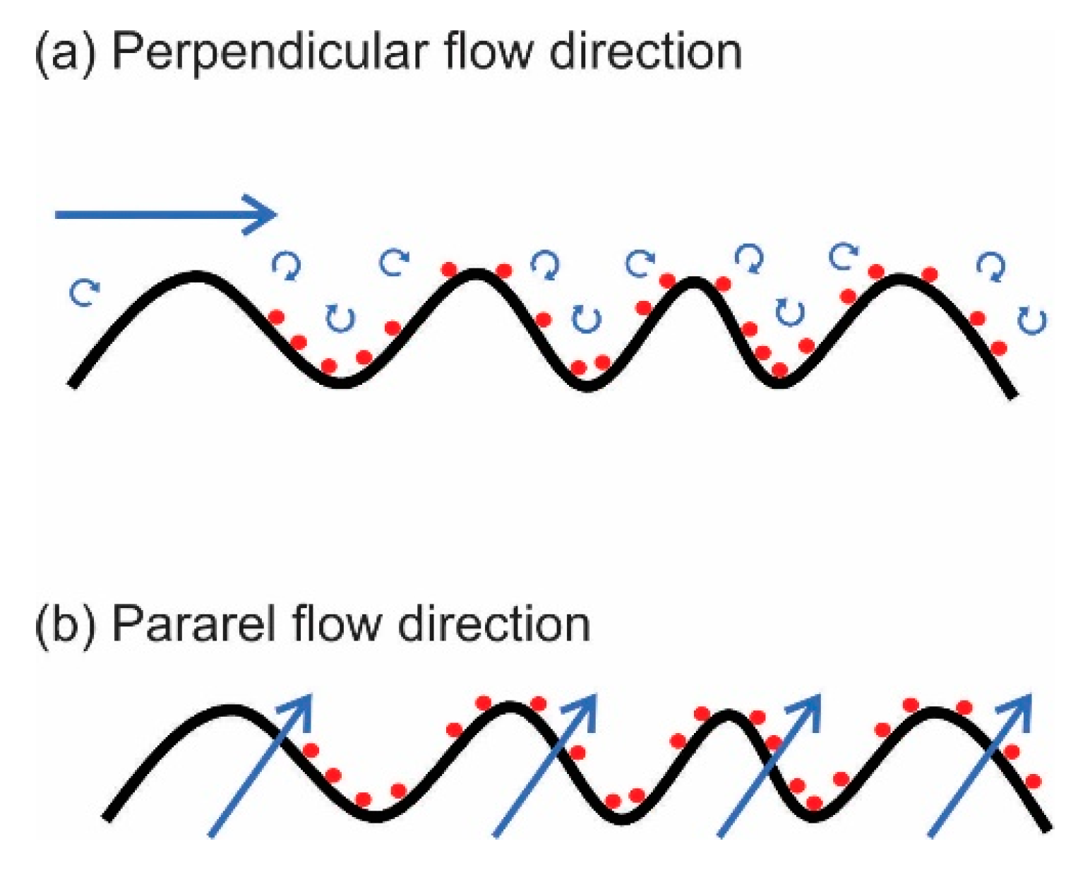
| 3D printing | BSA | Reduced normalized flux: 19–24% with parallel stripes, 13% with flat (no pattern) and 5% with perpendicular stripes | [84] |
| 3D printing | BSA | Wavy membrane has 10% better PWP than flat membrane. Wavy membrane has 87% PRR while flat has 53% | [78] |
| 3D printing | oil-in-water emulsion 0.3–0.5 vol % | Wavy membrane has 30% better PWP than flat membrane | [77] |
| Inkjet printing | Saline water | ~26.4% increase in permeance and ~97.2% salt rejection | [68] |
| TEM | BSA | 104% increase in flux recovery ratio ~91% in permeance | [85] |
| NIL | 2000 ppm NaCl solution | 240% improvement in permeability | [31] |
| NIL | 1 g/L NaCl solution | 22% improvement in permeability at 0.01 wt % MDP concentration | [86] |
© 2019 by the authors. Licensee MDPI, Basel, Switzerland. This article is an open access article distributed under the terms and conditions of the Creative Commons Attribution (CC BY) license (http://creativecommons.org/licenses/by/4.0/).
Share and Cite
Barambu, N.U.; Bilad, M.R.; Wibisono, Y.; Jaafar, J.; Mahlia, T.M.I.; Khan, A.L. Membrane Surface Patterning as a Fouling Mitigation Strategy in Liquid Filtration: A Review. Polymers 2019, 11, 1687. https://doi.org/10.3390/polym11101687
Barambu NU, Bilad MR, Wibisono Y, Jaafar J, Mahlia TMI, Khan AL. Membrane Surface Patterning as a Fouling Mitigation Strategy in Liquid Filtration: A Review. Polymers. 2019; 11(10):1687. https://doi.org/10.3390/polym11101687
Chicago/Turabian StyleBarambu, Nafiu Umar, Muhammad Roil Bilad, Yusuf Wibisono, Juhana Jaafar, Teuku Meurah Indra Mahlia, and Asim Laeeq Khan. 2019. "Membrane Surface Patterning as a Fouling Mitigation Strategy in Liquid Filtration: A Review" Polymers 11, no. 10: 1687. https://doi.org/10.3390/polym11101687
APA StyleBarambu, N. U., Bilad, M. R., Wibisono, Y., Jaafar, J., Mahlia, T. M. I., & Khan, A. L. (2019). Membrane Surface Patterning as a Fouling Mitigation Strategy in Liquid Filtration: A Review. Polymers, 11(10), 1687. https://doi.org/10.3390/polym11101687