Fabrication of High Quality, Large Wet Lay-Up/Vacuum Bag Laminates by Sliding a Magnetic Tool


Abstract

1. Introduction
2. Materials and Methods
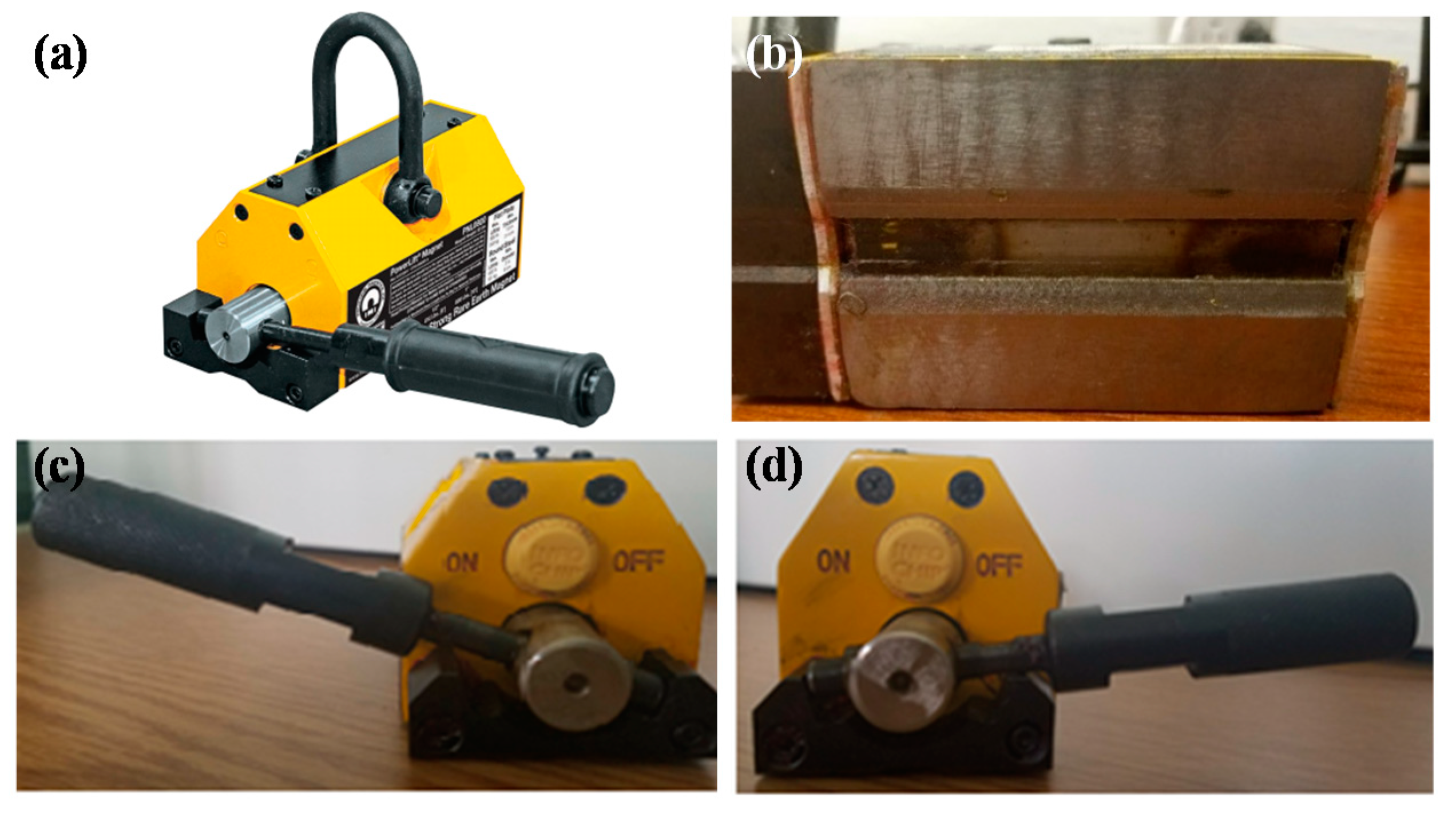
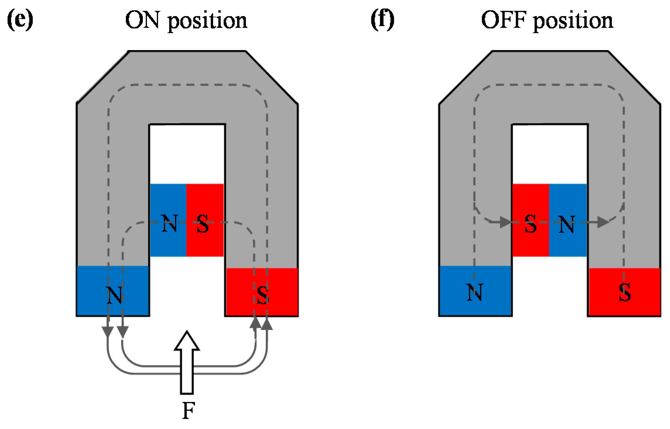
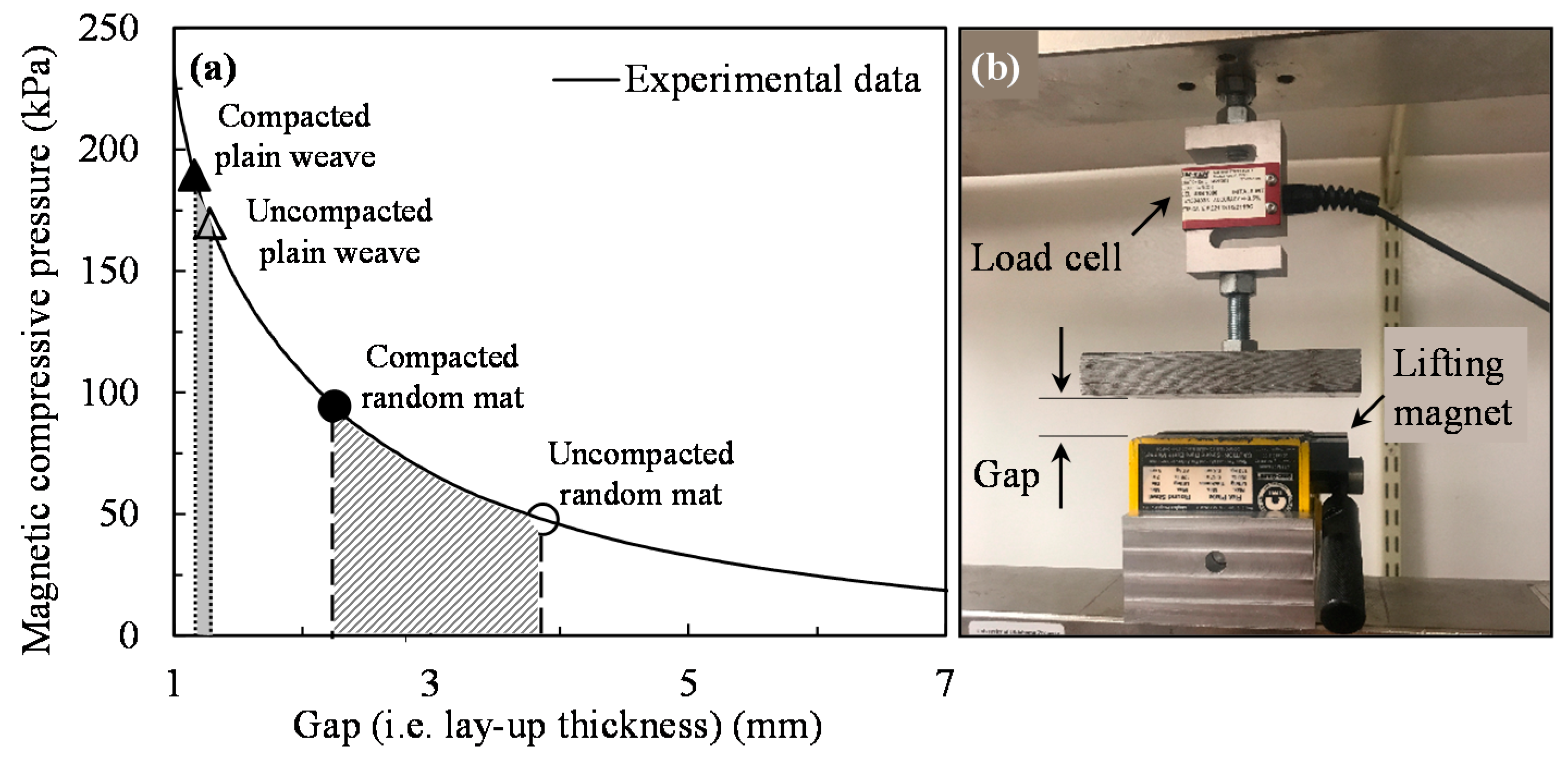
2.1. Lifting Magnet
2.2. Composite Constituents
2.3. Laminate Manufacturing
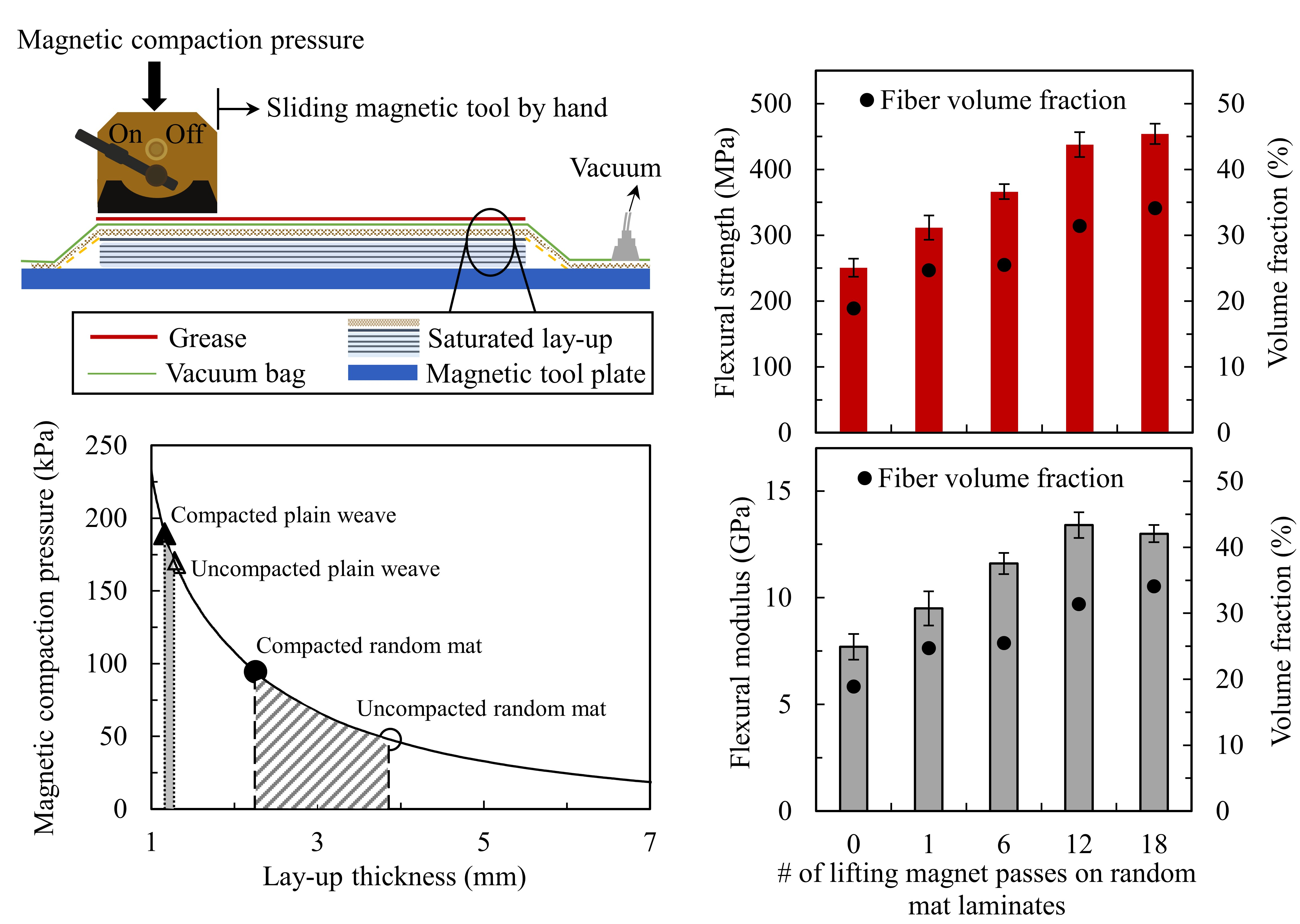
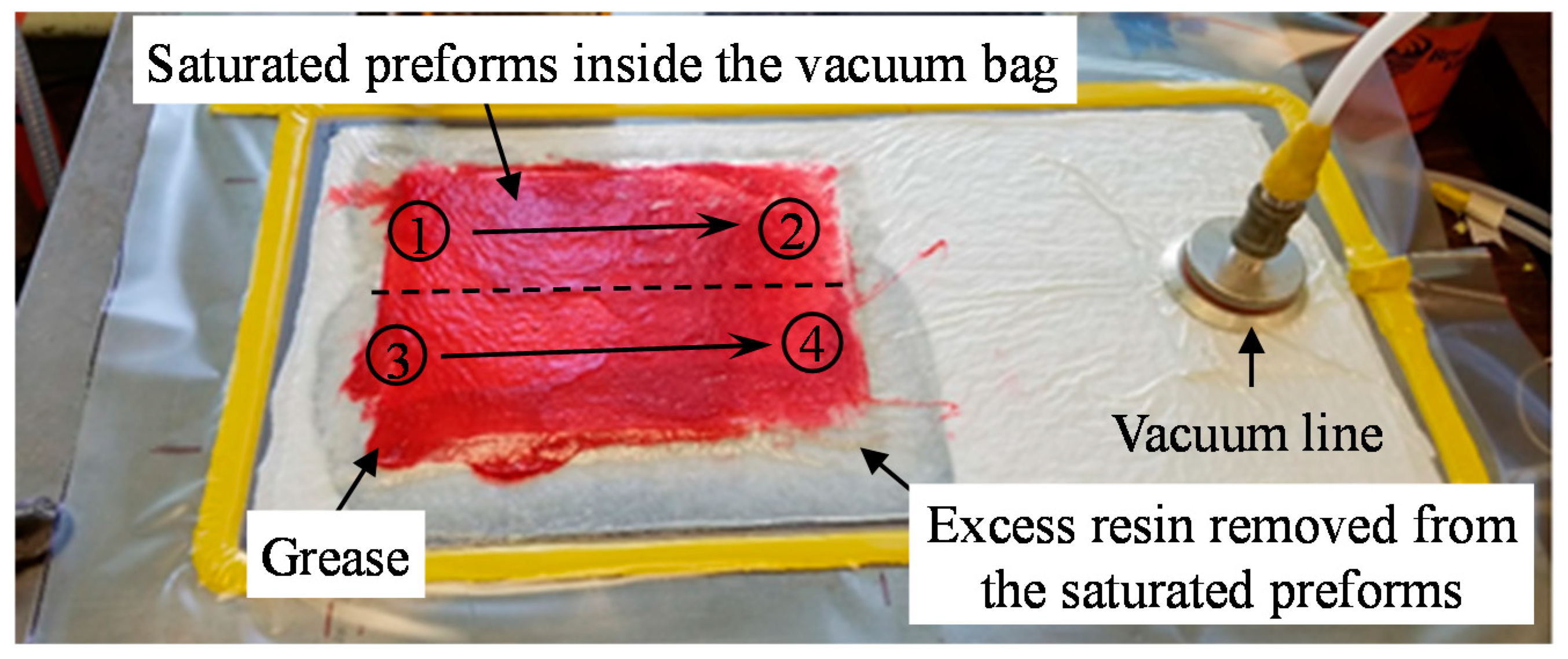
2.4. Applying the Lifting Magnet during Fabrication
2.5. Void and Fiber Volume Fraction Measurement
2.6. Scanning Electron Microscopy: Sample Preparation and Imaging
2.7. Characterization of Mechanical Properties
3. Results and Discussion
3.1. Laminate Thickness, Fiber Volume Fraction, and Void Content
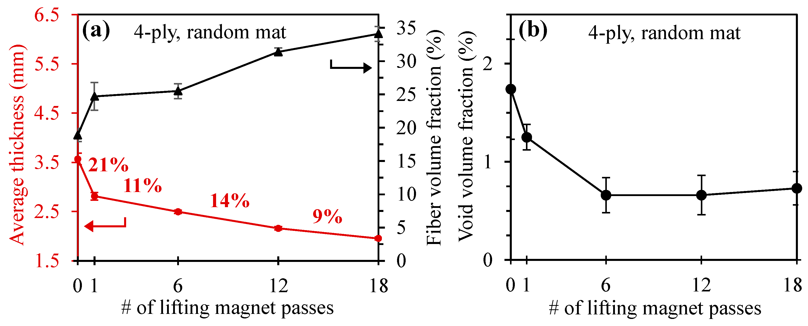
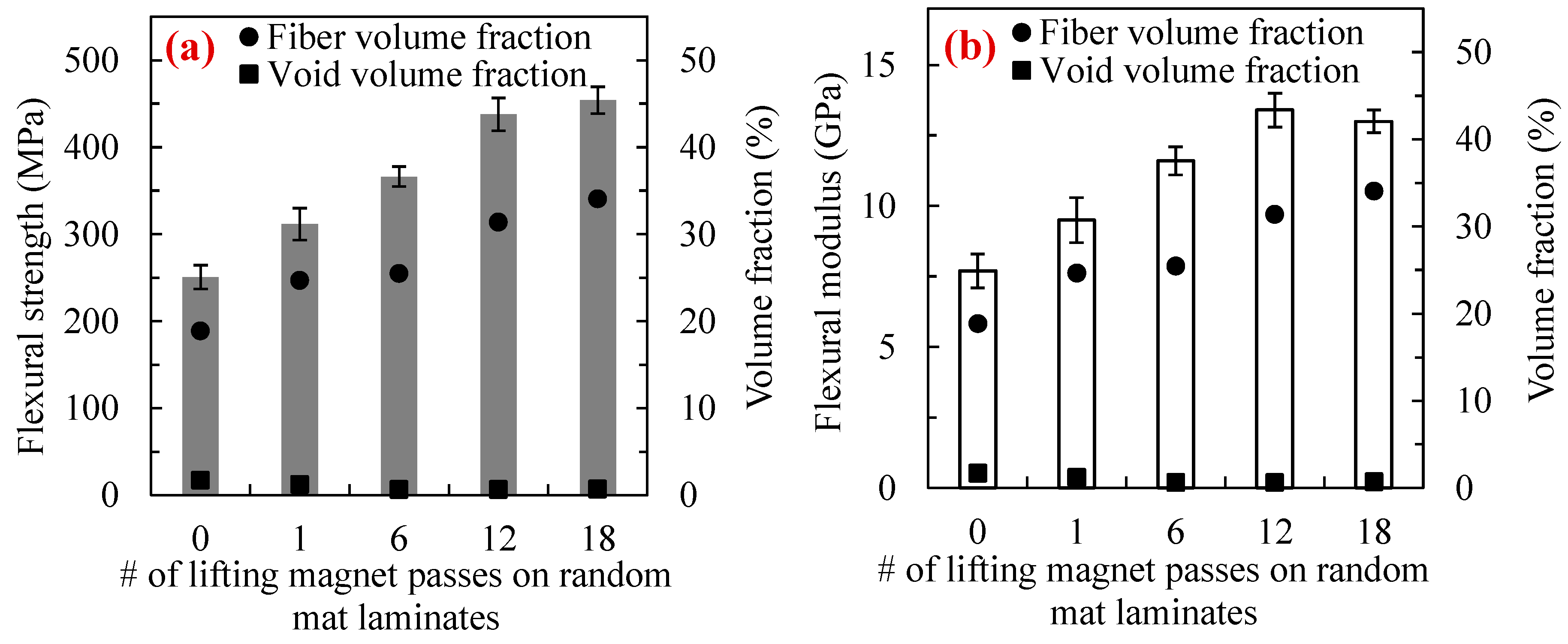
3.1.1. Random Mat
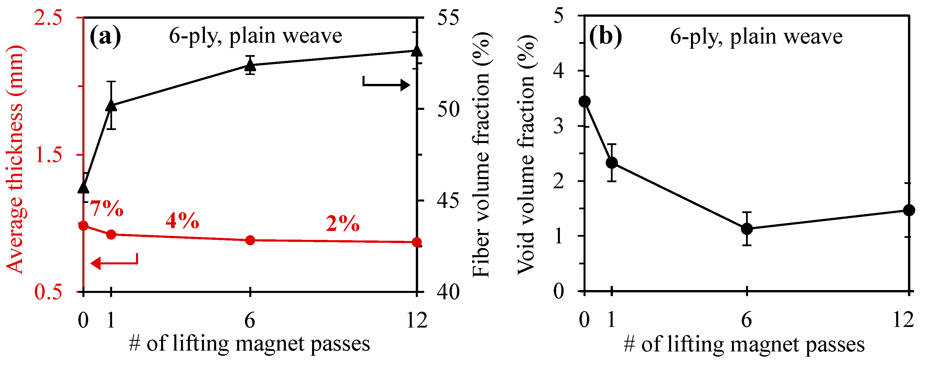
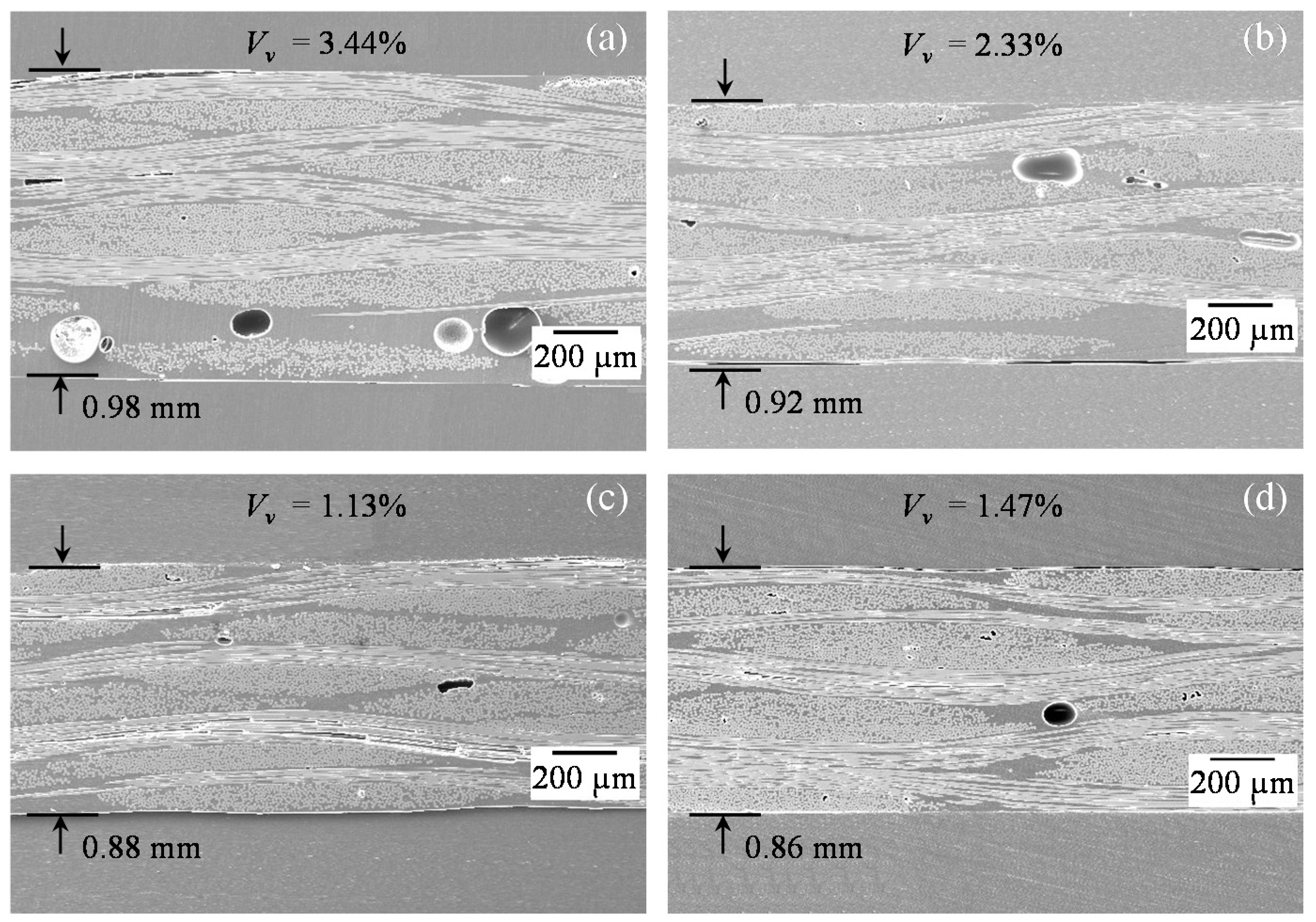
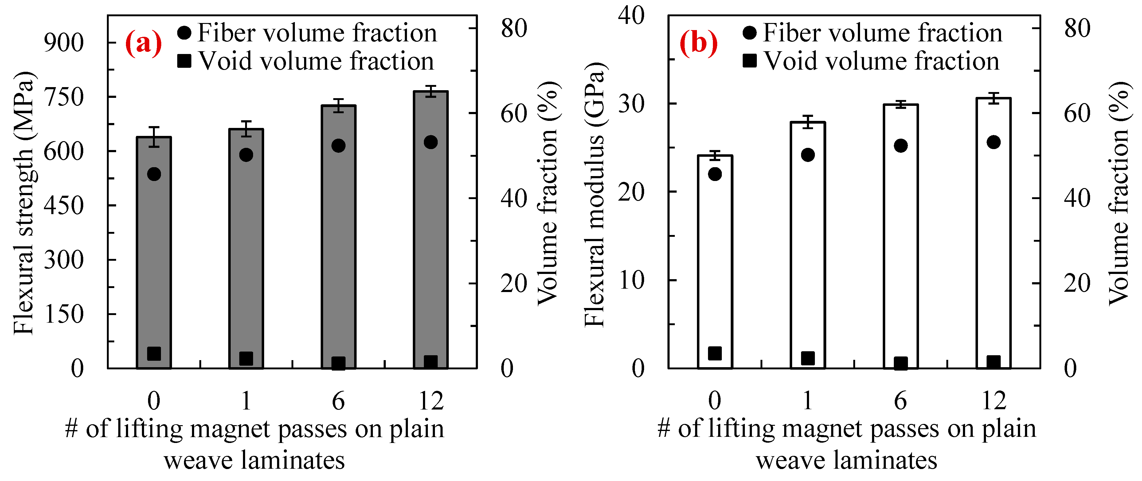
3.1.2. Plain Weave
3.2. Microstructural Analysis
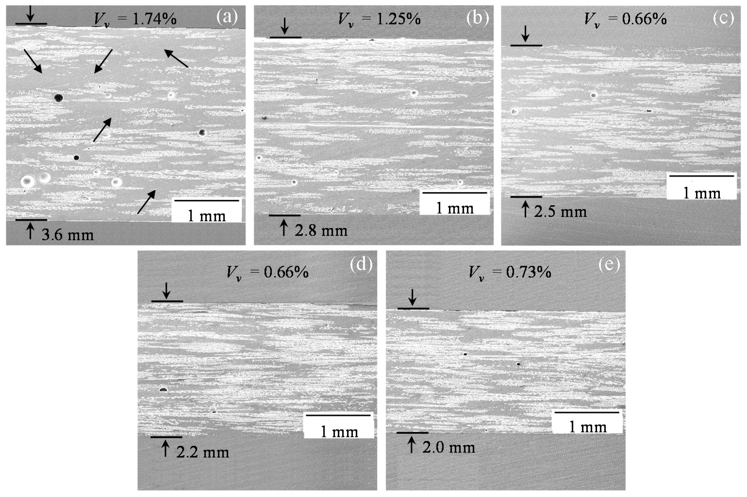
3.2.1. Random Mat
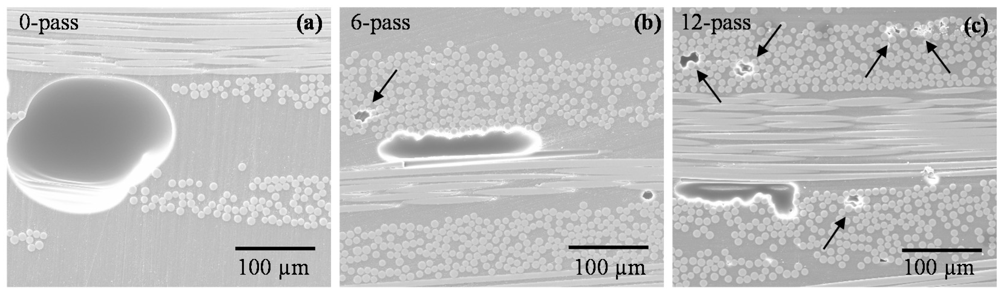
3.2.2. Plain Weave
3.3. Flexural Strength and Modulus
3.3.1. Random Mat
3.3.2. Plain Weave
4. Conclusions
Author Contributions
Funding
Conflicts of Interest
References
- Zimmermann, R.; Rolfes, R. Posicoss—Improved postbuckling simulation for design of fibre composite stiffened fuselage structures. Compos. Struct. 2006, 73, 171–174. [Google Scholar] [CrossRef]
- Awerbuch, J.; Leone, F.A., Jr.; Ozevin, D.; Tan, T.-M. On the applicability of acoustic emission to identify modes of damage in full-scale composite fuselage structures. J. Compos. Mater. 2016, 50, 447–469. [Google Scholar] [CrossRef]
- Ren, P.; Zhou, J.; Tian, A.; Ye, R.; Shi, L.; Zhang, W.; Huang, W. Experimental investigation on dynamic failure of carbon/epoxy laminates under underwater impulsive loading. Mar. Struct. 2018, 59, 285–300. [Google Scholar] [CrossRef]
- Garcia-Espinel, J.D.; Castro-Fresno, D.; Gayo, P.P.; Ballester-Muñoz, F. Effects of sea water environment on glass fiber reinforced plastic materials used for marine civil engineering constructions. Mater. Des. 2015, 66, 46–50. [Google Scholar] [CrossRef]
- Machado, J.; Gamarra, P.M.-R.; Marques, E.A.S.; da Silva, L.F.M. Improvement in impact strength of composite joints for the automotive industry. Compos. Part B Eng. 2018, 138, 243–255. [Google Scholar] [CrossRef]
- Mårtensson, P.; Zenkert, D.; Åkermo, M. Effects of manufacturing constraints on the cost and weight efficiency of integral and differential automotive composite structures. Compos. Struct. 2015, 134, 572–578. [Google Scholar] [CrossRef]
- Belingardi, G.; Cavatorta, M.P.; Paolino, D.S. Repeated impact response of hand lay-up and vacuum infusion thick glass reinforced laminates. Int. J. Impact Eng. 2008, 35, 609–619. [Google Scholar] [CrossRef]
- Manimaran, R.; Jayakumar, I.; Mohammad Giyahudeen, R.; Narayanan, L. Mechanical properties of fly ash composites—A review. Energy Source Part A 2018, 40, 887–893. [Google Scholar] [CrossRef]
- Javaid, U.; Khan, Z.M.; Khan, M.B.; Bassyouni, M.; Abdel-Hamid, S.M.-S.; Abdel-Aziz, M.H.; ul Hasan, S.W. Fabrication and thermo-mechanical characterization of glass fiber/vinyl ester wind turbine rotor blade. Compos. Part B Eng. 2016, 91, 257–266. [Google Scholar] [CrossRef]
- Sutherland, L.S.; Soares, C.G. Impact behaviour of typical marine composite laminates. Compos. Part B Eng. 2005, 37, 89–100. [Google Scholar] [CrossRef]
- Karbhari, V.M. Fiber reinforced composite bridge systems––Transition from the laboratory to the field. Compos. Struct. 2004, 66, 5–16. [Google Scholar] [CrossRef]
- Balakrishnan, V.S.; Seidlitz, H. Potential repair techniques for automotive composites: A review. Compos. Part B Eng. 2018, 145, 28–38. [Google Scholar] [CrossRef]
- Atas, C.; Akgun, Y.; Dagdelen, O.; Icten, B.M.; Sarikanat, M. An experimental investigation on the low velocity impact response of composite plates repaired by VARIM and hand lay-up processes. Compos. Struct. 2011, 93, 1178–1186. [Google Scholar] [CrossRef]
- Karbhari, V.M.; Seible, F. Fiber reinforced composites—Advanced materials for the renewal of civil infrastructure. Appl. Compos. Mater. 2000, 7, 95–124. [Google Scholar] [CrossRef]
- Found, M.S.; Friend, M.J. Evaluation of CFRP panels with scarf repair patches. Compos. Struct. 1995, 32, 115–122. [Google Scholar] [CrossRef]
- Stringer, L. Optimization of the wet lay-up/vacuum bag process for the fabrication of carbon fibre epoxy composites with high fibre fraction and low void content. Composites 1989, 20, 441–452. [Google Scholar] [CrossRef]
- Uddin, N.; Vaidya, U.; Shohel, M.; Serrano-Perez, J.C. Cost-effective bridge girder strengthening using vacuum-assisted resin transfer molding (VARTM). Adv. Compos. Mater. 2004, 13, 255–281. [Google Scholar] [CrossRef]
- Brouwer, W.D.; Van Herpt, E.C.F.C.; Labordus, M. Vacuum injection moulding for large structural applications. Compos. Part A Appl. Sci. Manuf. 2003, 34, 551–558. [Google Scholar] [CrossRef]
- Rydarowski, H.; Koziol, M. Repeatability of glass fiber reinforced polymer laminate panels manufactured by hand lay-up and vacuum-assisted resin infusion. J. Compos. Mater. 2015, 49, 573–586. [Google Scholar] [CrossRef]
- Ghose, S.; Watson, K.A.; Cano, R.J.; Britton, S.M.; Jensen, B.J.; Connell, J.W.; Herring, H.M.; Lineberry, Q.J. High temperature VARTM of phenylethynyl terminated imides. High Perform. Polym. 2009, 21, 653–672. [Google Scholar] [CrossRef]
- Yalcinkaya, M.A.; Sozer, E.M.; Altan, M.C. Fabrication of high quality composite laminates by pressurized and heated-VARTM. Compos. Part A Appl. Sci. Manuf. 2017, 102, 336–346. [Google Scholar] [CrossRef]
- Fu, X.; Zhang, C.; Liang, R.; Wang, B.; Fielding, J.C. High temperature vacuum-assisted resin transfer molding of phenylethynyl terminated imide composites. Polym. Compos. 2011, 32, 52–58. [Google Scholar] [CrossRef]
- Chang, T.; Zhan, L.; Tan, W.; Li, S. Effect of autoclave pressure on interfacial properties at micro-and macro-level in polymer-matrix composite laminates. Fibers Polym. 2017, 18, 1614–1622. [Google Scholar] [CrossRef]
- Abraham, D.; Matthews, S.; McIlhagger, R. A comparison of physical properties of glass fibre epoxy composites produced by wet lay-up with autoclave consolidation and resin transfer moulding. Compos. Part A Appl. Sci. Manuf. 1998, 29, 795–801. [Google Scholar] [CrossRef]
- Anderson, J.P.; Altan, M.C. Formation of voids in composite laminates: Coupled effect of moisture content and processing pressure. Polym. Compos. 2015, 36, 376–384. [Google Scholar] [CrossRef]
- Grunenfelder, L.K.; Nutt, S.R. Void formation in composite prepregs—Effect of dissolved moisture. Compos. Sci. Technol. 2010, 70, 2304–2309. [Google Scholar] [CrossRef]
- Gupta, N.; Sundaram, R. Fiber optic sensors for monitoring flow in vacuum enhanced resin infusion technology (VERITy) process. Compos. Part A Appl. Sci. Manuf. 2009, 40, 1065–1070. [Google Scholar] [CrossRef]
- Choi, H.S.; Ahn, K.J.; Nam, J.-D.; Chun, H.J. Hygroscopic aspects of epoxy/carbon fiber composite laminates in aircraft environments. Compos. Part A Appl. Sci. Manuf. 2001, 32, 709–720. [Google Scholar] [CrossRef]
- Xia, C.; Shi, S.Q.; Cai, L. Vacuum-assisted resin infusion (VARI) and hot pressing for CaCO3 nanoparticle treated kenaf fiber reinforced composites. Compos. Part B Eng. 2015, 78, 138–143. [Google Scholar] [CrossRef]
- Hagnell, M.K.; Åkermo, M. A composite cost model for the aeronautical industry: Methodology and case study. Compos. Part B Eng. 2015, 79, 254–261. [Google Scholar] [CrossRef]
- Amirkhosravi, M.; Pishvar, M.; Altan, M.C. Improving laminate quality in wet lay-up/vacuum bag processes by magnet assisted composite manufacturing (MACM). Compos. Part A Appl. Sci. Manuf. 2017, 98, 227–237. [Google Scholar] [CrossRef]
- Pishvar, M.; Amirkhosravi, M.; Altan, M.C. Magnet assisted composite manufacturing: A novel fabrication technique for high-quality composite laminates. Polym. Compos. 2017. [Google Scholar] [CrossRef]
- Pishvar, M.; Amirkhosravi, M.; Altan, M.C. Magnet assisted composite manufacturing: A flexible new technique for achieving high consolidation pressure in vacuum bag/lay-up processes. J. Vis. Exp. 2018, 135, e57254. [Google Scholar] [CrossRef] [PubMed]
- Amirkhosravi, M.; Pishvar, M.; Altan, M.C. Void reduction in VARTM composites by compaction of dry fiber preforms with stationary and moving magnets. J. Compos. Mater. 2018. [Google Scholar] [CrossRef]
- Robitaille, F.; Gauvin, R. Compaction of textile reinforcements for composites manufacturing. III: Reorganization of the fiber network. Polym. Compos. 1999, 20, 48–61. [Google Scholar] [CrossRef]
- Robitaille, F.; Gauvin, R. Compaction of textile reinforcements for composites manufacturing. II: Compaction and relaxation of dry and H2O-saturated woven reinforcements. Polym. Compos. 1998, 19, 543–557. [Google Scholar] [CrossRef]
- Yang, J.; Xiao, J.; Zeng, J.; Jiang, D.; Peng, C. Compaction behavior and part thickness variation in vacuum infusion molding process. Appl. Compos. Mater. 2012, 19, 443–458. [Google Scholar] [CrossRef]
- Meier, R.; Kahraman, I.; Seyhan, A.T.; Zaremba, S.; Drechsler, K. Evaluating vibration assisted vacuum infusion processing of hexagonal boron nitride sheet modified carbon fabric/epoxy composites in terms of interlaminar shear strength and void content. Compos. Sci. Technol. 2016, 128, 94–103. [Google Scholar] [CrossRef]
- Maragoni, L.; Carraro, P.A.; Quaresimin, M. Effect of voids on the crack formation in a [45/−45/0]s laminate under cyclic axial tension. Compos. Part A Appl. Sci. Manuf. 2016, 91, 493–500. [Google Scholar] [CrossRef]
- Hamidi, Y.K.; Aktas, L.; Altan, M.C. Three-dimensional features of void morphology in resin transfer molded composites. Compos. Sci. Technol. 2005, 65, 1306–1320. [Google Scholar] [CrossRef]
- Yalcinkaya, M.A.; Sozer, E.M.; Altan, M.C. Dynamic pressure control in VARTM: Rapid fabrication of laminates with high fiber volume fraction and improved dimensional uniformity. Polym. Compos. 2018, in press. [Google Scholar]
- Parnas, R.S.; Howard, J.G.; Luce, T.L.; Advani, S.G. Permeability characterization. Part 1: A proposed standard reference fabric for permeability. Polym. Compos. 1995, 16, 429–445. [Google Scholar] [CrossRef]
- De Morais, W.A.; Monteiro, S.N.; de Almeida, J.R.M. Evaluation of repeated low energy impact damage in carbon–epoxy composite materials. Compos. Struct. 2005, 67, 307–315. [Google Scholar] [CrossRef]
- Chong, H.M.; Liu, S.L.; Subramanian, A.S.; Ng, S.P.; Tay, S.W.; Wang, S.Q.; Feih, S. Out-of-autoclave scarf repair of interlayer toughened carbon fibre composites using double vacuum debulking of patch. Compos. Part A Appl. Sci. Manuf. 2018, 107, 224–234. [Google Scholar] [CrossRef]
- Zhang, A.; Lu, H.; Zhang, D. Research on the mechanical properties prediction of carbon/epoxy composite laminates with different void contents. Polym. Compos. 2016, 37, 14–20. [Google Scholar] [CrossRef]
- Agius, S.L.; Fox, B.L. Rapidly cured out-of-autoclave laminates: Understanding and controlling the effect of voids on laminate fracture toughness. Compos. Part A Appl. Sci. Manuf. 2015, 73, 186–194. [Google Scholar] [CrossRef]
- Hernández, S.; Sket, F.; Molina-Aldareguı, J.M.; González, C.; LLorca, J. Effect of curing cycle on void distribution and interlaminar shear strength in polymer-matrix composites. Compos. Sci. Technol. 2011, 71, 1331–1341. [Google Scholar] [CrossRef]
- Costa, M.L.; Rezende, M.C.; de Almeida, S.F.M. Effect of void content on the moisture absorption in polymeric composites. Polym. Plast. Technol. Eng. 2006, 45, 691–698. [Google Scholar] [CrossRef]
- Amirkhosravi, M.; Pishvar, M.; Altan, M.C. Fabricating high-quality VARTM laminates by magnetic consolidation: Experiments and process model. Compos. Part A Appl. Sci. Manuf. 2018. [Google Scholar] [CrossRef]


| Magnetic Characteristic | Values |
|---|---|
| Magnet material | Neodymium |
| Working load limit (flat) | 113 kg |
| Weight | 3.17 kg |
| Overall length × width × height | 12.7 × 6.7 × 6.7 cm3 |
| Contact surface area | 35 cm2 |
| Maximum operating temperature | 82 °C |
| Fabrication Scenario | Manufacturing Process | Fabric Type | No. of Plies |
|---|---|---|---|
| WLVB-RM-4-0 | Conventional WLVB | Random mat | 4 |
| WLVB-RM-4-1 | WLVB with 1 pass of lifting magnet | ||
| WLVB-RM-4-6 | WLVB with 6 passes of lifting magnet | ||
| WLVB-RM-4-12 | WLVB with 12 passes of lifting magnet | ||
| WLVB-RM-4-18 | WLVB with 18 passes of lifting magnet | ||
| WLVB-PW-6-0 | Conventional WLVB | Plain weave | 6 |
| WLVB-PW-6-1 | WLVB with 1 pass of lifting magnet | ||
| WLVB-PW-6-6 | WLVB with 6 passes of lifting magnet | ||
| WLVB-PW-6-12 | WLVB with 12 passes of lifting magnet |
| Fabrication Case | Thickness (mm) | Fiber Volume Fraction (%) | Void Volume Fraction (%) |
|---|---|---|---|
| WLVB-RM-4-0 | 3.567 ± 0.119 | 18.9 ± 1.0 | 1.74 ± 0.56 |
| WLVB-RM-4-1 | 2.811 ± 0.079 | 24.7 ± 2.4 | 1.25 ± 0.15 |
| WLVB-RM-4-6 | 2.496 ± 0.035 | 25.5 ± 1.2 | 0.66 ± 0.20 |
| WLVB-RM-4-12 | 2.158 ± 0.034 | 31.4 ± 0.7 | 0.66 ± 0.22 |
| WLVB-RM-4-18 | 1.954 ± 0.031 | 34.1 ± 1.2 | 0.73 ± 0.19 |
| WLVB-PW-6-0 | 0.982 ± 0.009 | 45.7 ± 0.8 | 3.44 ± 0.46 |
| WLVB-PW-6-1 | 0.918 ± 0.007 | 50.2 ± 1.5 | 2.33 ± 0.37 |
| WLVB-PW-6-6 | 0.877 ± 0.004 | 52.4 ± 0.6 | 1.13 ± 0.33 |
| WLVB-PW-6-12 | 0.863 ± 0.006 | 53.1 ± 1.1 | 1.47 ± 0.54 |
© 2018 by the authors. Licensee MDPI, Basel, Switzerland. This article is an open access article distributed under the terms and conditions of the Creative Commons Attribution (CC BY) license (http://creativecommons.org/licenses/by/4.0/).
Share and Cite
Sussmann, M.; Amirkhosravi, M.; Pishvar, M.; Altan, M.C. Fabrication of High Quality, Large Wet Lay-Up/Vacuum Bag Laminates by Sliding a Magnetic Tool. Polymers 2018, 10, 992. https://doi.org/10.3390/polym10090992
Sussmann M, Amirkhosravi M, Pishvar M, Altan MC. Fabrication of High Quality, Large Wet Lay-Up/Vacuum Bag Laminates by Sliding a Magnetic Tool. Polymers. 2018; 10(9):992. https://doi.org/10.3390/polym10090992
Chicago/Turabian StyleSussmann, Marli, Mehrad Amirkhosravi, Maya Pishvar, and M. Cengiz Altan. 2018. "Fabrication of High Quality, Large Wet Lay-Up/Vacuum Bag Laminates by Sliding a Magnetic Tool" Polymers 10, no. 9: 992. https://doi.org/10.3390/polym10090992
APA StyleSussmann, M., Amirkhosravi, M., Pishvar, M., & Altan, M. C. (2018). Fabrication of High Quality, Large Wet Lay-Up/Vacuum Bag Laminates by Sliding a Magnetic Tool. Polymers, 10(9), 992. https://doi.org/10.3390/polym10090992