Enduring and Stable Surface Dielectric Barrier Discharge (SDBD) Plasma Using Fluorinated Multi-Layered Polyimide


Abstract
1. Introduction
2. SDBD Device and Experimental Set up
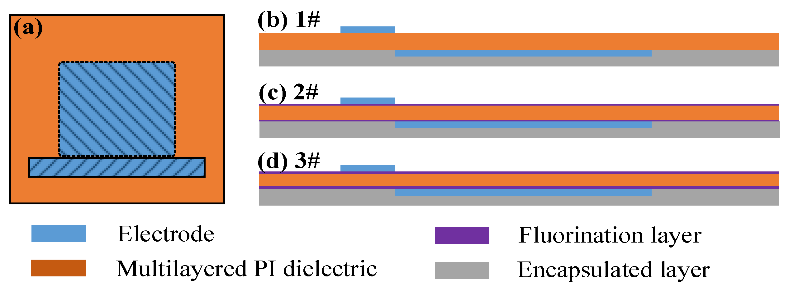
2.1. SDBD Device
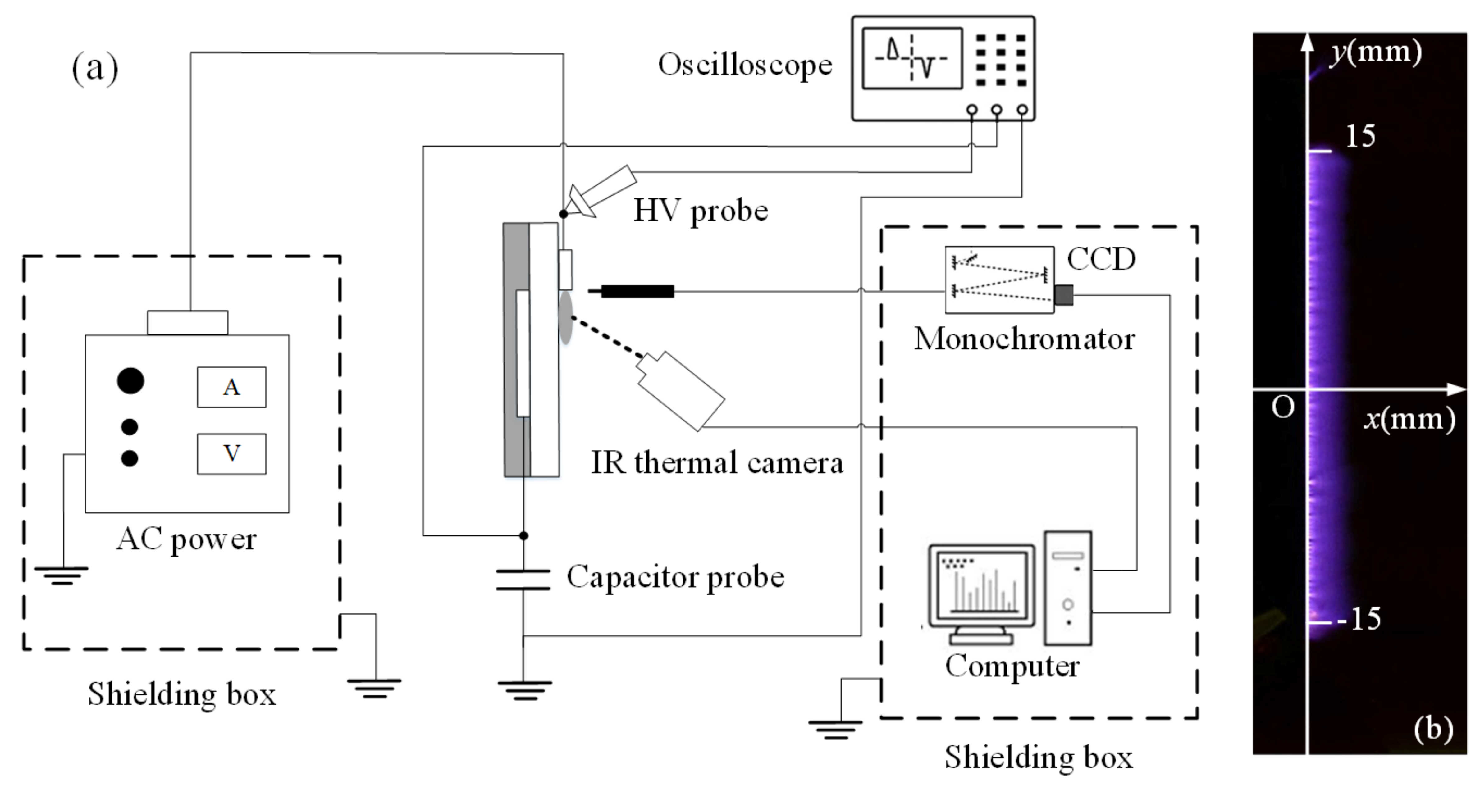
2.2. Experimental Setup
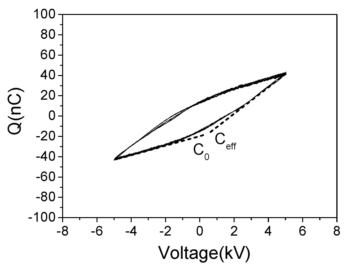
2.3. Power Consumption and Dielectric Capacitance Calculation
3. Results and Discussion
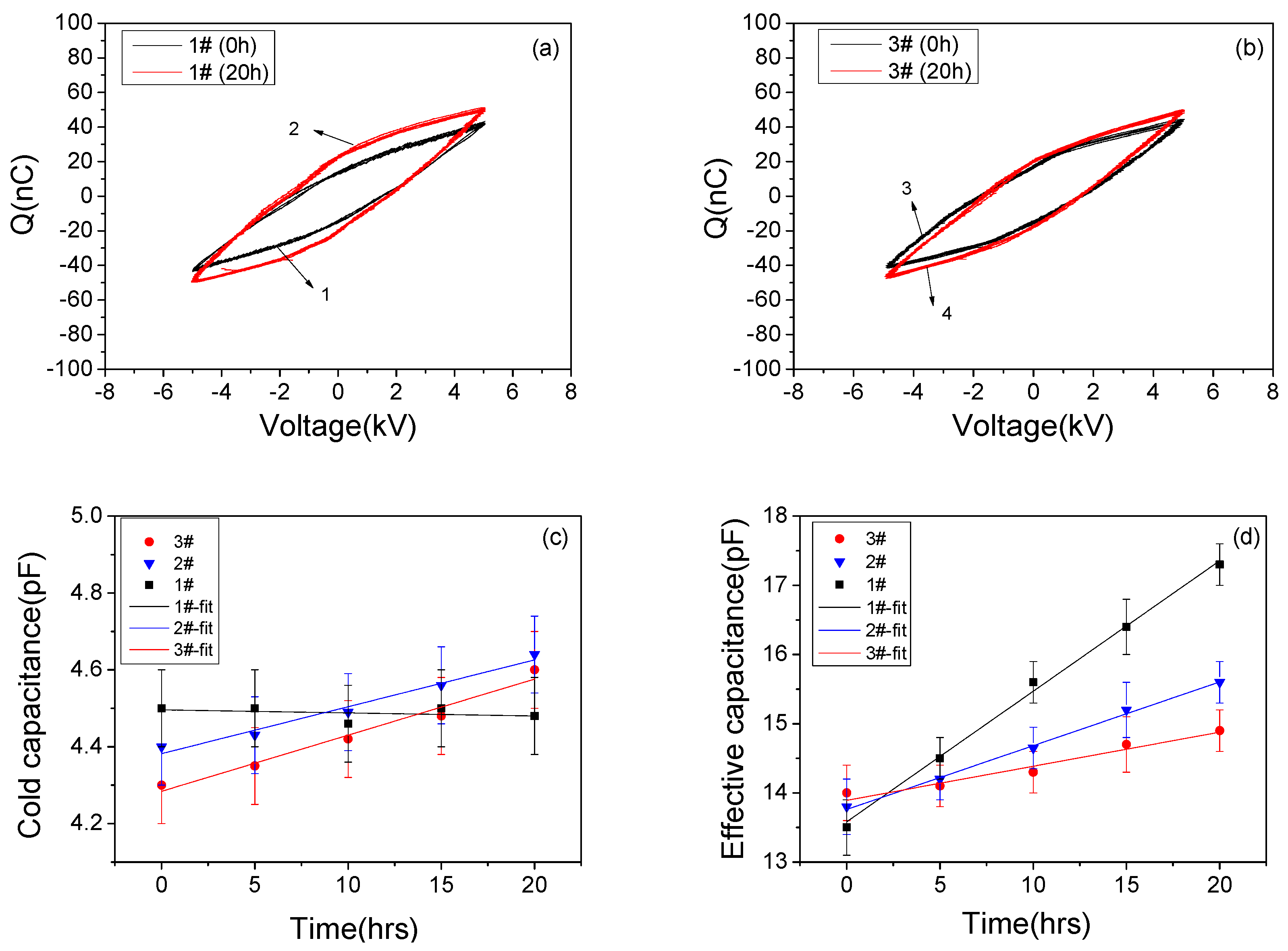
3.1. Discharge Properties
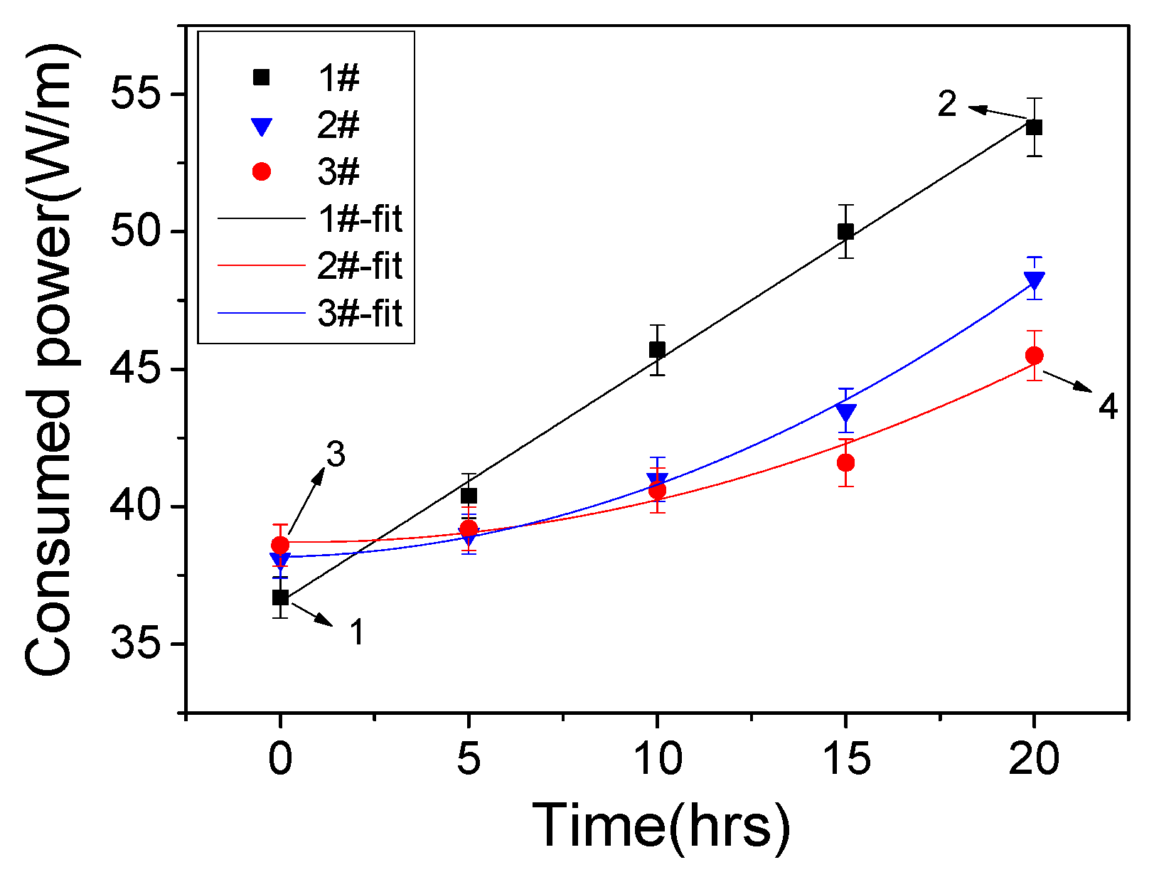
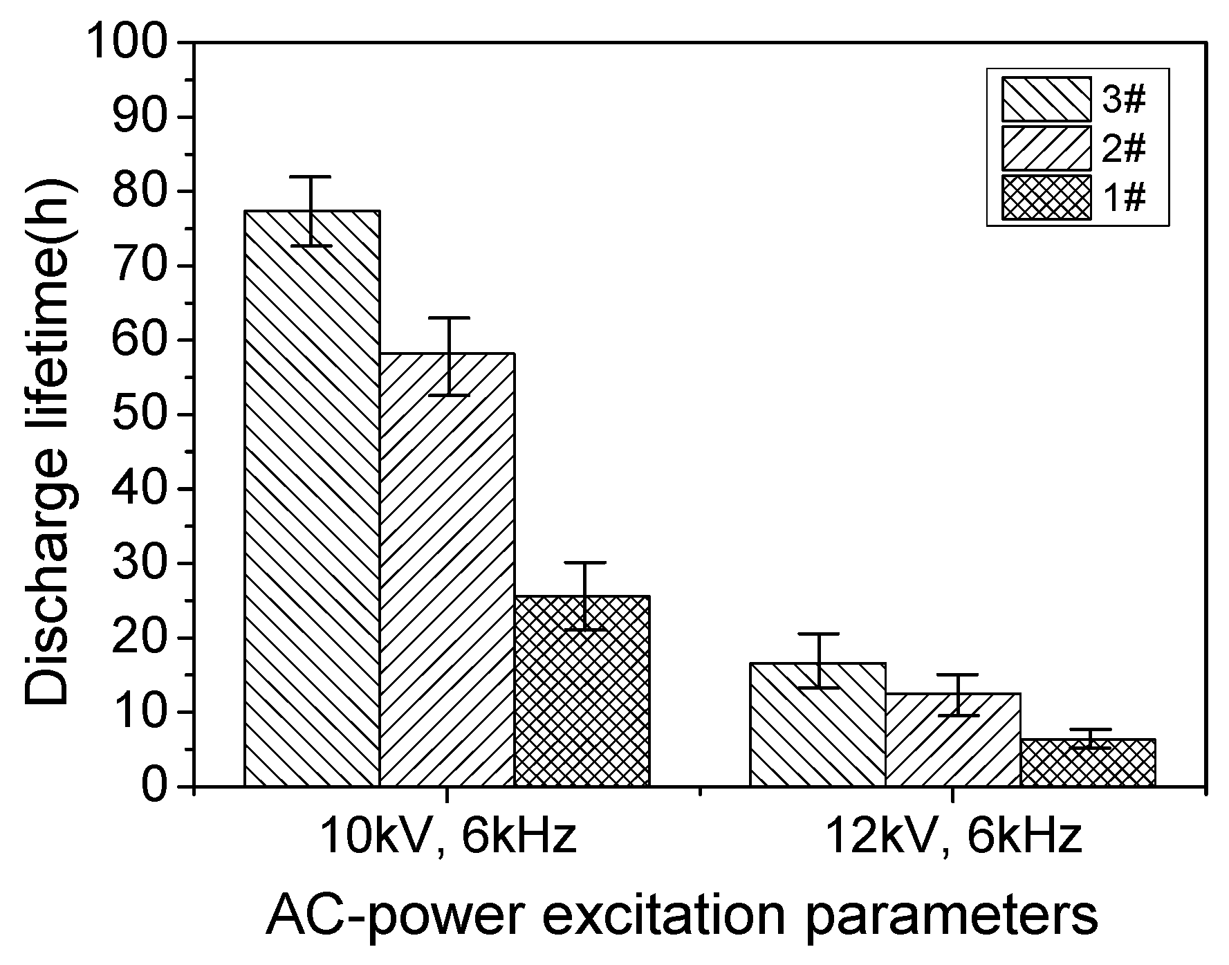
3.2. Dielectric Lifetime
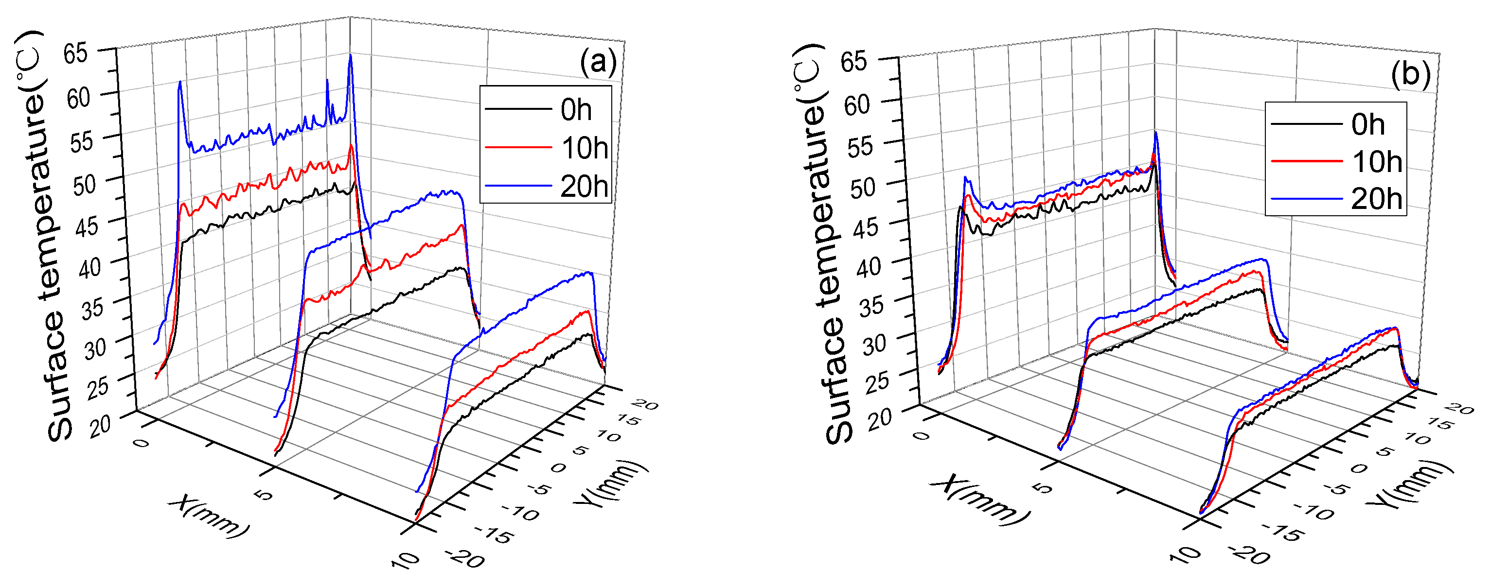
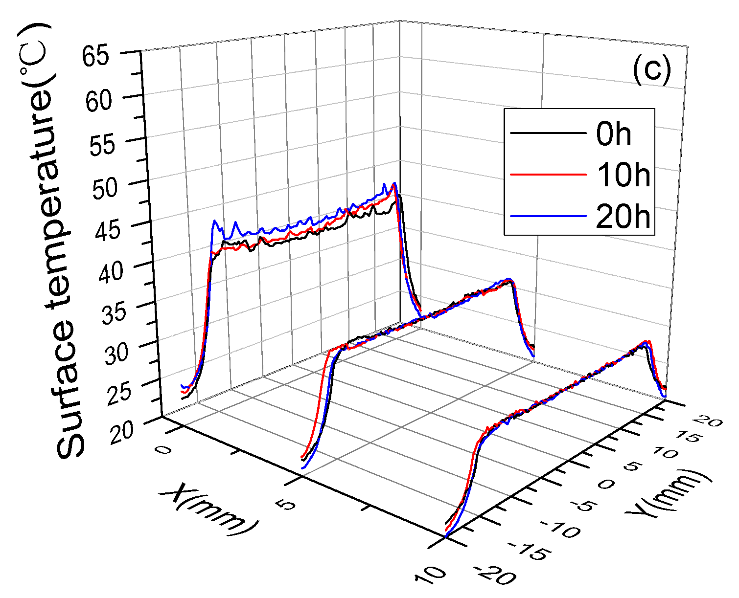
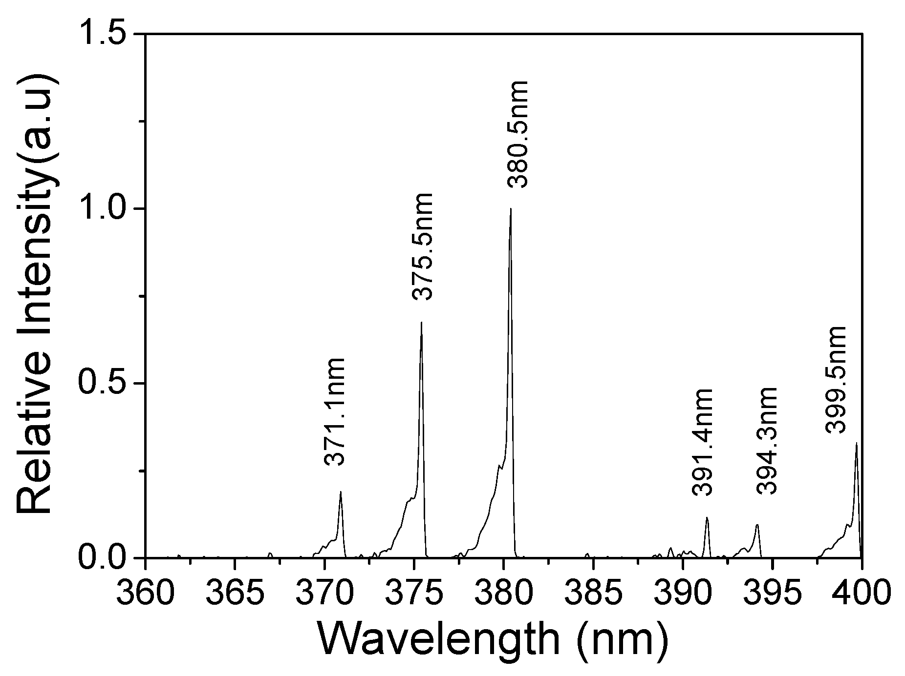
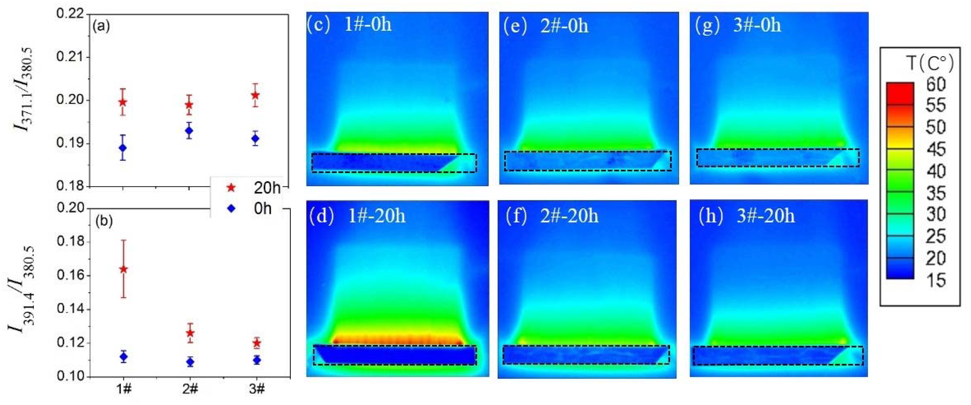
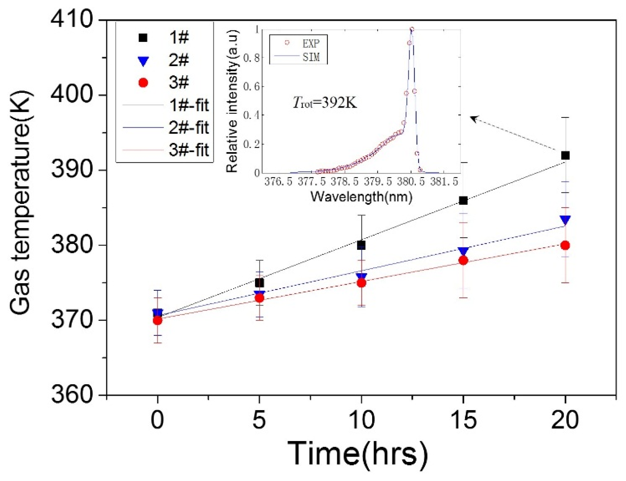
3.3. Surface Temperature and Plasma Diagnosis
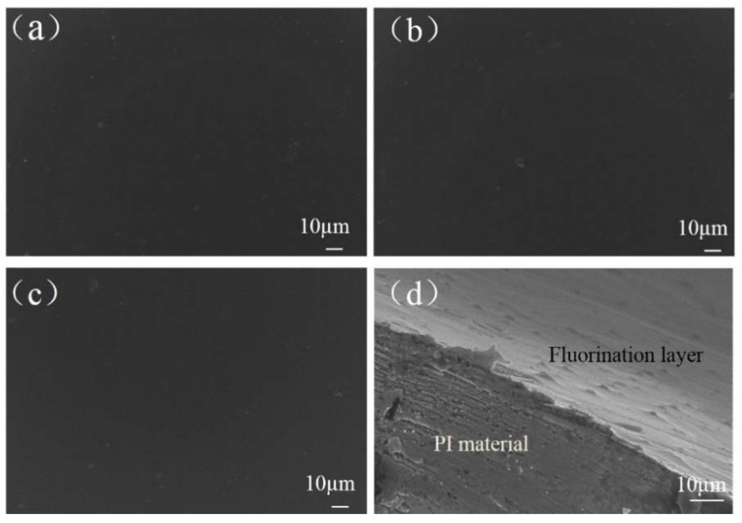
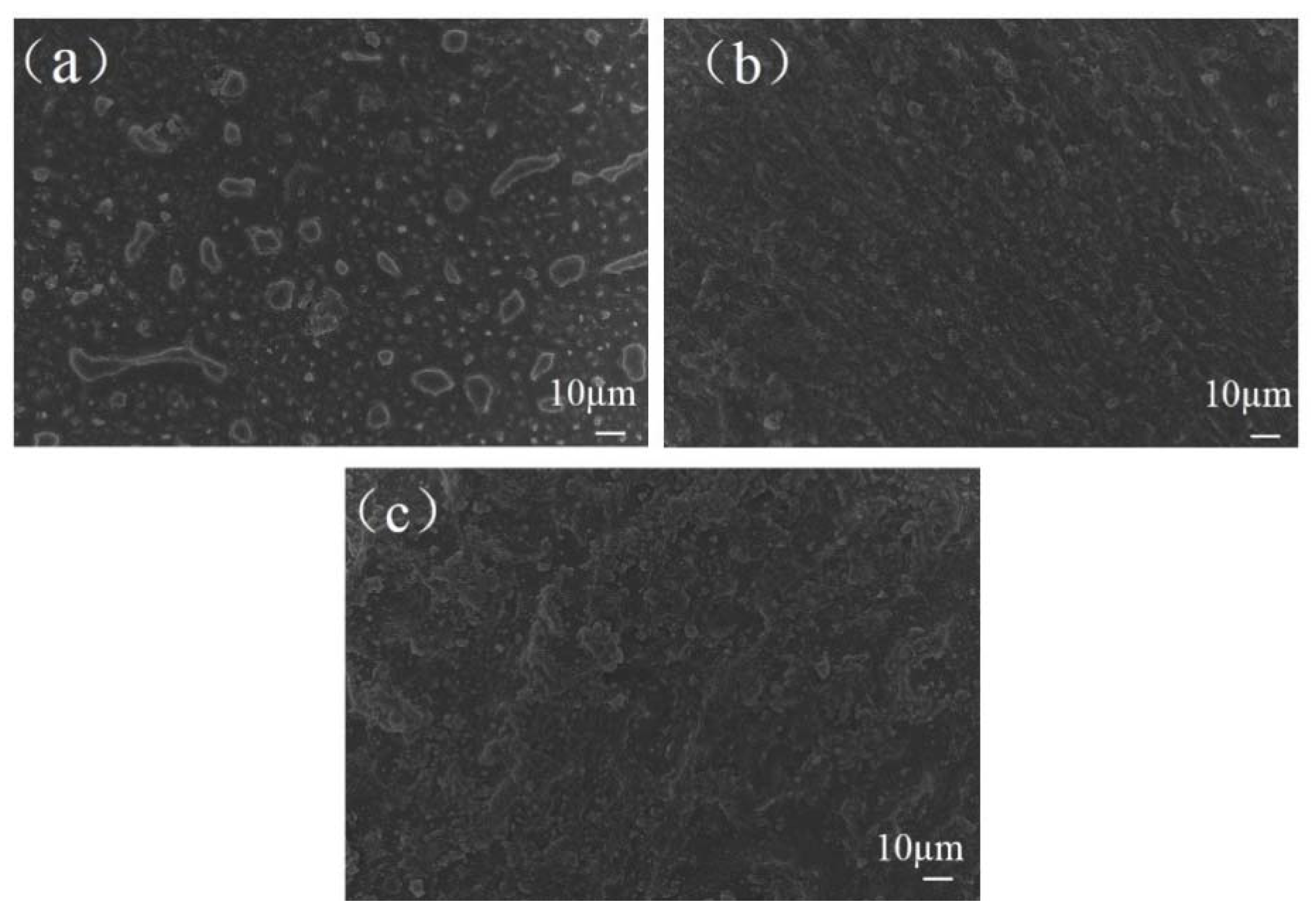
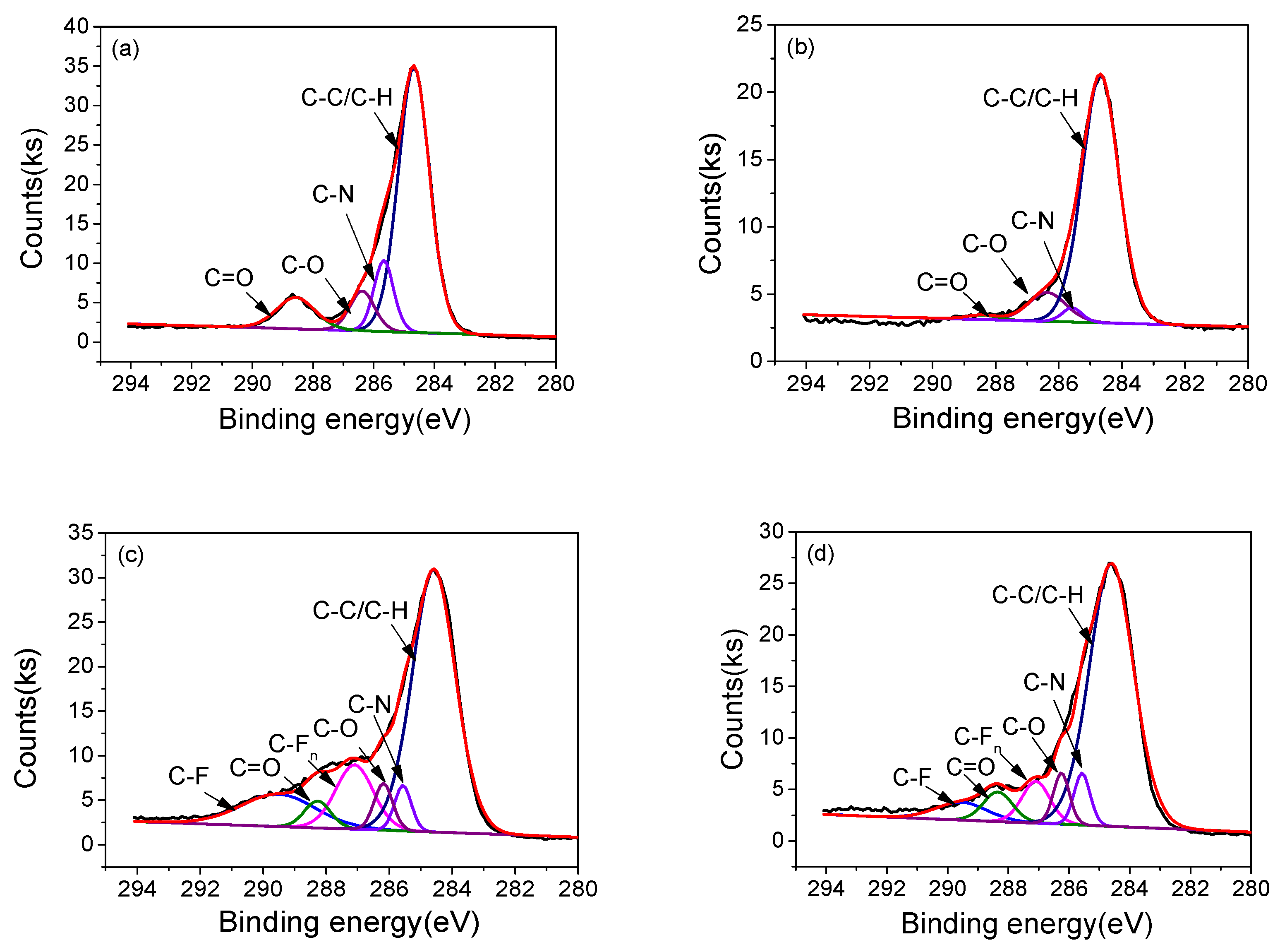
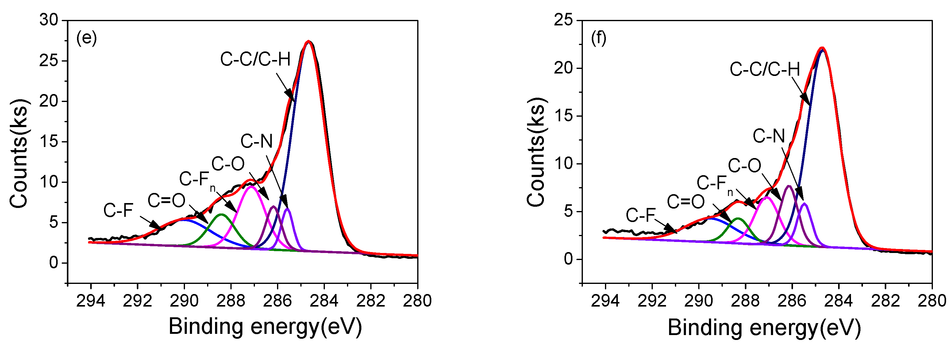
3.4. Surface Morphology and Chemical Structure
4. Discussion
5. Conclusions
Author Contributions
Acknowledgments
Conflicts of Interest
References
- Wang, C.; Zhang, G.; Wang, X.; He, X. The effect of air plasma on barrier dielectric surface in dielectric barrier discharge. Appl. Surf. Sci. 2010, 257, 1698–1702. [Google Scholar] [CrossRef]
- Kriegseis, J.; Simon, B.; Grundmann, S. Towards in-flight applications? A review on dielectric barrier discharge-based boundary-layer control. Appl. Mech. Rev. 2016, 68, 020802. [Google Scholar] [CrossRef]
- Brandenburg, R. Dielectric barrier discharges: Progress on plasma sources and on the understanding of regimes and single filaments. Plasma Sources Sci. Technol. 2017, 26, 053001. [Google Scholar] [CrossRef]
- Bian, D.L.; Wu, Y.; Jia, M.; Long, C.B. PI/Al2O3 nanocomposite based long lifetime surface dielectric barrier discharge plasma actuator. Sens. Actuat A-Phys. 2017, 267, 90–98. [Google Scholar] [CrossRef]
- Meng, X.; Cai, J.; Tian, Y.; Han, X.; Zhang, D.; Hu, H. Experimental Study of Anti-icing and Deicing on a Cylinder by DBD plasma actuation. In Proceedings of the 47th AIAA Plasmadynamics and Lasers Conference, Washington, DC, USA, 13–17 June 2016. [Google Scholar]
- Roy, S.; Wang, C. Numerical investigation of three-dimensional plasma actuation for improving film cooling effectiveness. J. Thermophys. Heat Transf. 2013, 27, 489–497. [Google Scholar] [CrossRef]
- Kim, H.Y.; Kang, S.K.; Kwon, H.C.; Lee, H.W.; Lee, J.K. Gas temperature effect on reactive species generation from the atmospheric pressure air plasma. Plasma Process. Polym. 2013, 10, 686–697. [Google Scholar] [CrossRef]
- Abdelaziz, A.; Ishijima, T.; Seto, T.; Osawa, N.; Wedaa, H.; Otani, Y. Characterization of surface dielectric barrier discharge influenced by intermediate frequency for ozone production. Plasma Sources Sci. Technol. 2016, 25, 035012. [Google Scholar] [CrossRef]
- Jiang, N.; Guo, L.; Shang, K.; Lu, N.; Li, J.; Wu, Y. Discharge and optical characterizations of nanosecond pulse sliding dielectric barrier discharge plasma for volatile organic compound degradation. J. Phys. D Appl. Phys. 2017, 50, 155206. [Google Scholar] [CrossRef]
- Malik, M.A.; Schoenbach, K.H.; Heller, R. Coupled surface dielectric barrier discharge reactor-ozone synthesis and nitric oxide conversion from air. Chem. Eng. J. 2014, 256, 222–229. [Google Scholar] [CrossRef]
- Jeon, J.; Rosentreter, T.M.; Li, Y.; Isbary, G.; Thomas, H.M.; Zimmermann, J.L.; Morfill, G.E.; Shimizu, T. Bactericidal Agents Produced by Surface Micro-Discharge (SMD) Plasma by Controlling Gas Compositions. Plasma Process. Polym. 2014, 11, 426–436. [Google Scholar] [CrossRef]
- Pons, J.; Oukacine, L.; Moreau, E.; Tatibouet, J.M. Observation of dielectric degradation after surface dielectric barrier discharge operation in air at atmospheric pressure. IEEE Trans. Plasma Sci. 2008, 36, 1342–1343. [Google Scholar] [CrossRef]
- Ennis, C.P.; Kaiser, R.I. Mechanistical studies on the electron-induced degradation of polymethylmethacrylate and Kapton. Phys. Chem. Chem. Phys. 2010, 12, 14902. [Google Scholar] [CrossRef] [PubMed]
- Hanson, R.E.; Houser, N.M.; Lavoie, P. Dielectric material degradation monitoring of dielectric barrier discharge plasma actuators. J. Appl. Phys. 2014, 115, 043301. [Google Scholar] [CrossRef]
- Ndong, A.C.; Zouzou, N.; Benard, N.; Moreau, E. Effect of dielectric aging on the behavior of a surface nanosecond pulsed dielectric barrier discharge. IEEE Trans. Dielectr. Electr. Insul. 2013, 20, 1554–1560. [Google Scholar] [CrossRef]
- Rigit, A.; Lai, K.; Bong, D. Degradation of a dielectric barrier discharge plasma actuator. In Proceedings of the 9th International Conference on Properties and Applications of Dielectric Materials, Harbin, China, 19–23 July 2009. [Google Scholar]
- Kharitonov, A.P. Direct fluorination of polymers—From fundamental research to industrial applications. Prog. Org. Coat. 2008, 61, 192–204. [Google Scholar] [CrossRef]
- An, Z.; Chen, X.; Liu, C.; Zheng, F.; Zhang, Y. Significantly reduced fluorination time needed for suppression of space charge in polyethylene by increasing the fluorination temperature. J. Phys. D Appl. Phys. 2012, 45, 385303. [Google Scholar] [CrossRef]
- Tressaud, A.; Durand, E.; Labrugere, C.; Kharitonov, A.; Kharitonova, L. Modification of surface properties of carbon-based and polymeric materials through fluorination routes: From fundamental research to industrial applications. J. Fluorine Chem. 2007, 128, 378–391. [Google Scholar] [CrossRef]
- An, Z.; Yang, Q.; Xie, C.; Jiang, Y.; Zheng, F.; Zhang, Y. Suppression effect of surface fluorination on charge injection into linear low density polyethylene. J. Appl. Phys. 2009, 105, 13. [Google Scholar] [CrossRef]
- An, Z.; Liu, C.; Chen, X.; Zheng, F.; Zhang, Y. Correlation between space charge accumulation in polyethylene and its fluorinated surface layer characteristics. J. Phys. D Appl. Phys. 2011, 45, 35302–35309. [Google Scholar] [CrossRef]
- Du, B.X.; Li, J.; Du, W. Dynamic behavior of surface charge on direct-fluorinated polyimide films. IEEE Trans. Dielectr. Electr. Insul. 2013, 20, 947–954. [Google Scholar] [CrossRef]
- Du, B.X.; Li, J.; Du, H.; Yin, Y. Effect of surface fluorination on space charge behavior in multilayered polyimide films. IEEE Trans. Dielectr. Electr. Insul. 2014, 21, 1817–1823. [Google Scholar] [CrossRef]
- Hur, M.; Kang, W.S.; Lee, J.O.; Song, Y.H. Surface treatment of polyimide substrates using dielectric barrier discharge reactors based on l-shaped electrodes. Plasma Chem. Plasma Process 2015, 35, 231–246. [Google Scholar] [CrossRef]
- Shao, T.; Zhang, C.; Long, K.; Zhang, D.; Wang, J.; Yan, P.; Zhou, Y. Surface modification of polyimide films using unipolar nanosecond-pulse DBD in atmospheric air. Appl. Surf. Sci. 2010, 256, 3888–3894. [Google Scholar] [CrossRef]
- Wang, R.; Zhang, C.; Liu, X.; Xie, Q.; Yan, P.; Shao, T. Microsecond pulse driven Ar/CF4 plasma jet for polymethylmethacrylate surface modification at atmospheric pressure. Appl. Surf. Sci. 2015, 328, 509–515. [Google Scholar] [CrossRef]
- Miron, C.; Hulubei, C.; Sava, I.; Quade, A.; Steuer, A.; Weltmann, K.; Kolb, J.F. Polyimide Film Surface Modification by Nanosecond High Voltage Pulse Driven Electrical Discharges in Water. Plasma Process. Polym. 2015, 12, 734–745. [Google Scholar] [CrossRef]
- Dong-liang, B.; Yun, W.; Mia, J. Characterization of surface dielectric barrier discharge (SDBD) based on PI/Al2O3 nanocomposite. Plasma Process Polym. 2018, e1700236. [Google Scholar] [CrossRef]
- Tirumala, R.; Benard, N.; Moreau, E.; Fenot, M.; Lalizel, G.; Dorignac, E. Temperature characterization of dielectric barrier discharge actuators: Influence of electrical and geometric parameters. J. Phys. D Appl. Phys. 2014, 47, 255203. [Google Scholar] [CrossRef]
- Joussot, R.; Hong, D.; Rabat, H.; Boucinha, V.; Weber-Rozenbaum, R. Thermal Characterization of a DBD Plasma Actuator: Dielectric Temperature Measurements using Infrared Thermography. In Proceedings of the 40th Fluid Dynamics Conference and Exhibit, Chicago, IL, USA, 28 June–1 July 2010. [Google Scholar]
- Kriegseis, J.; Möller, B.; Grundmann, S.; Tropea, C. Capacitance and power consumption quantification of dielectric barrier discharge (DBD) plasma actuators. J. Electrosta. 2011, 69, 302–312. [Google Scholar] [CrossRef]
- Dave, H.; Ledwani, L.; Nema, S.K. Surface modification by atmospheric pressure air plasma treatment to improve dyeing with natural dyes: An environment friendly approach for leather processing. Plasma Chem. Plasma Process 2016, 36, 599–613. [Google Scholar] [CrossRef]
- Nassar, H.; Pellerin, S.; Musiol, K.; Martinie, O.; Pellerin, N. N2+/N2 ratio and temperature measurements based on the first negative N2+ and second positive N2 overlapped molecular emission spectra. J. Phys. D Appl. Phys. 2004, 37, 1904. [Google Scholar] [CrossRef]
- Mahoney, J.; Zhu, W.; Johnson, V.; Becker, K. Electrical and optical emission measurements of a capillary dielectric barrier discharge. Eur. Phys. J. D 2010, 60, 441–447. [Google Scholar] [CrossRef]
- Lianzhu, Z.; Shuxia, Z.; Xiulan, M. Characterization of nitrogen glow discharge plasma via optical emission spectrum simulation. Plasma Sci. Technol. 2008, 10, 455–462. [Google Scholar] [CrossRef]
- Wu, Y.; Li, Y.; Jia, M.; Song, H.; Su, C.; Pu, Y. Experimental investigation into characteristics of plasma aerodynamic actuation generated by dielectric barrier discharge. Chin. J. Aeronaut. 2010, 23, 39–45. [Google Scholar]
- Zhu, X.M.; Pu, X.K. Determining the electron temperature in inductively coupled nitrogen plasmas by optical emission spectroscopy with molecular kinetic effects. Phys. Plasmas 2005, 12, 103501. [Google Scholar] [CrossRef]
- Wu, Y.; Li, Y.; Jia, M.; Song, H.; Liang, H. Optical emission characteristics of surface nanosecond pulsed dielectric barrier discharge plasma. J. Appl. Phys. 2013, 113, 033303. [Google Scholar] [CrossRef]
- Luo, S.C.; Denning, C.M.; Scharer, J.E. Laser-rf creation and diagnostics of seeded atmospheric pressure air and nitrogen plasmas. J. Appl. Phys. 2008, 104, 013301. [Google Scholar] [CrossRef]
- Wagner, H.E.; Brandenburg, R.; Kozlov, K.V.; Sonnenfeld, A.; Michel, P.; Behnke, J.F. The barrier discharge: Basic properties and applications to surface treatment. Vacuum 2003, 71, 417–436. [Google Scholar] [CrossRef]
- Chen, S.; Wang, S.; Wang, Y.; Guo, B.; Li, G.; Chang, Z.; Zhang, G. Surface modification of epoxy resin using He/CF4 atmospheric pressure plasma jet for flashover withstanding characteristics improvement in vacuum. Appl. Surf. Sci. 2017, 414, 107. [Google Scholar] [CrossRef]
- Lemal, D.M. Perspective on fluorocarbon chemistry. J. Org. Chem. 2004, 69, 1–11. [Google Scholar] [CrossRef] [PubMed]
- Blanksby, S.J.; Ellis, G.B. Bond dissociation energies of organic molecules. Acct. Chem. Res. 2003, 36, 255–263. [Google Scholar] [CrossRef] [PubMed]


| Samples | Chemical composition (at %) | ||||
|---|---|---|---|---|---|
| C | N | O | F | Si | |
| 1#-0h | 78.32 | 3.87 | 17.81 | — | — |
| 1#-10h | 31.96 | 0.75 | 38.72 | — | 28.57 |
| 2#-0h | 54.28 | 3.7 | 14.94 | 27.08 | — |
| 2#-10h | 63.14 | 6.41 | 23.55 | 6.9 | — |
| 3#-0h | 52.14 | 3.88 | 16.91 | 27.07 | — |
| 3#-10h | 51.09 | 7.54 | 25.40 | 15.97 | — |
| Samples | Relative area of different chemical bonds (%) | |||||
|---|---|---|---|---|---|---|
| C 1s possible groups | ||||||
| C–C/C–H | C–N | C–O | C=O | C–Fn | C–F | |
| 1#-0h | 69.65 | 11.87 | 8.3 | 10.17 | — | — |
| 1#-10h | 85.78 | 2.64 | 10.26 | 1.32 | — | — |
| 2#-0h | 61.28 | 4.11 | 4.69 | 3.80 | 13.06 | 13.05 |
| 2#-10h | 71.58 | 5.15 | 5.09 | 2.76 | 7.21 | 5.63 |
| 3#-0h | 56.44 | 4.10 | 5.54 | 7.19 | 13.49 | 13.01 |
| 3#-10h | 57.21 | 5.64 | 9.94 | 5.06 | 10.94 | 11.21 |
© 2018 by the authors. Licensee MDPI, Basel, Switzerland. This article is an open access article distributed under the terms and conditions of the Creative Commons Attribution (CC BY) license (http://creativecommons.org/licenses/by/4.0/).
Share and Cite
Bian, D.; Wu, Y. Enduring and Stable Surface Dielectric Barrier Discharge (SDBD) Plasma Using Fluorinated Multi-Layered Polyimide. Polymers 2018, 10, 606. https://doi.org/10.3390/polym10060606
Bian D, Wu Y. Enduring and Stable Surface Dielectric Barrier Discharge (SDBD) Plasma Using Fluorinated Multi-Layered Polyimide. Polymers. 2018; 10(6):606. https://doi.org/10.3390/polym10060606
Chicago/Turabian StyleBian, Dongliang, and Yun Wu. 2018. "Enduring and Stable Surface Dielectric Barrier Discharge (SDBD) Plasma Using Fluorinated Multi-Layered Polyimide" Polymers 10, no. 6: 606. https://doi.org/10.3390/polym10060606
APA StyleBian, D., & Wu, Y. (2018). Enduring and Stable Surface Dielectric Barrier Discharge (SDBD) Plasma Using Fluorinated Multi-Layered Polyimide. Polymers, 10(6), 606. https://doi.org/10.3390/polym10060606