Carbon Nanotube-Based Organic Thermoelectric Materials for Energy Harvesting

Abstract
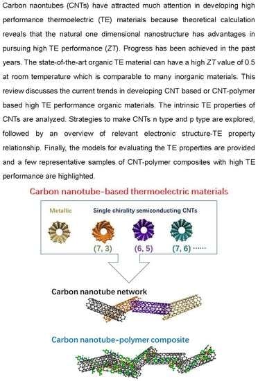
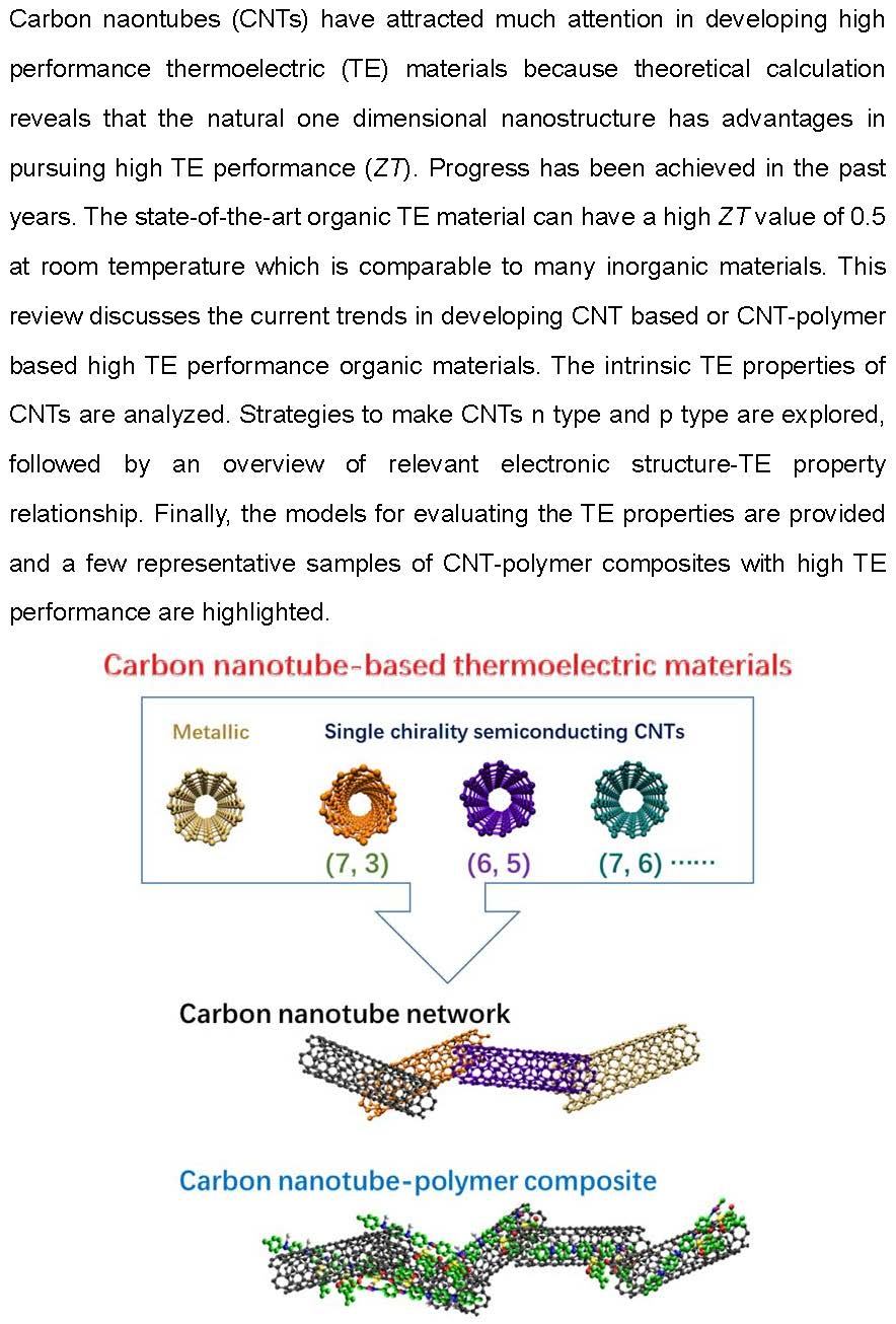
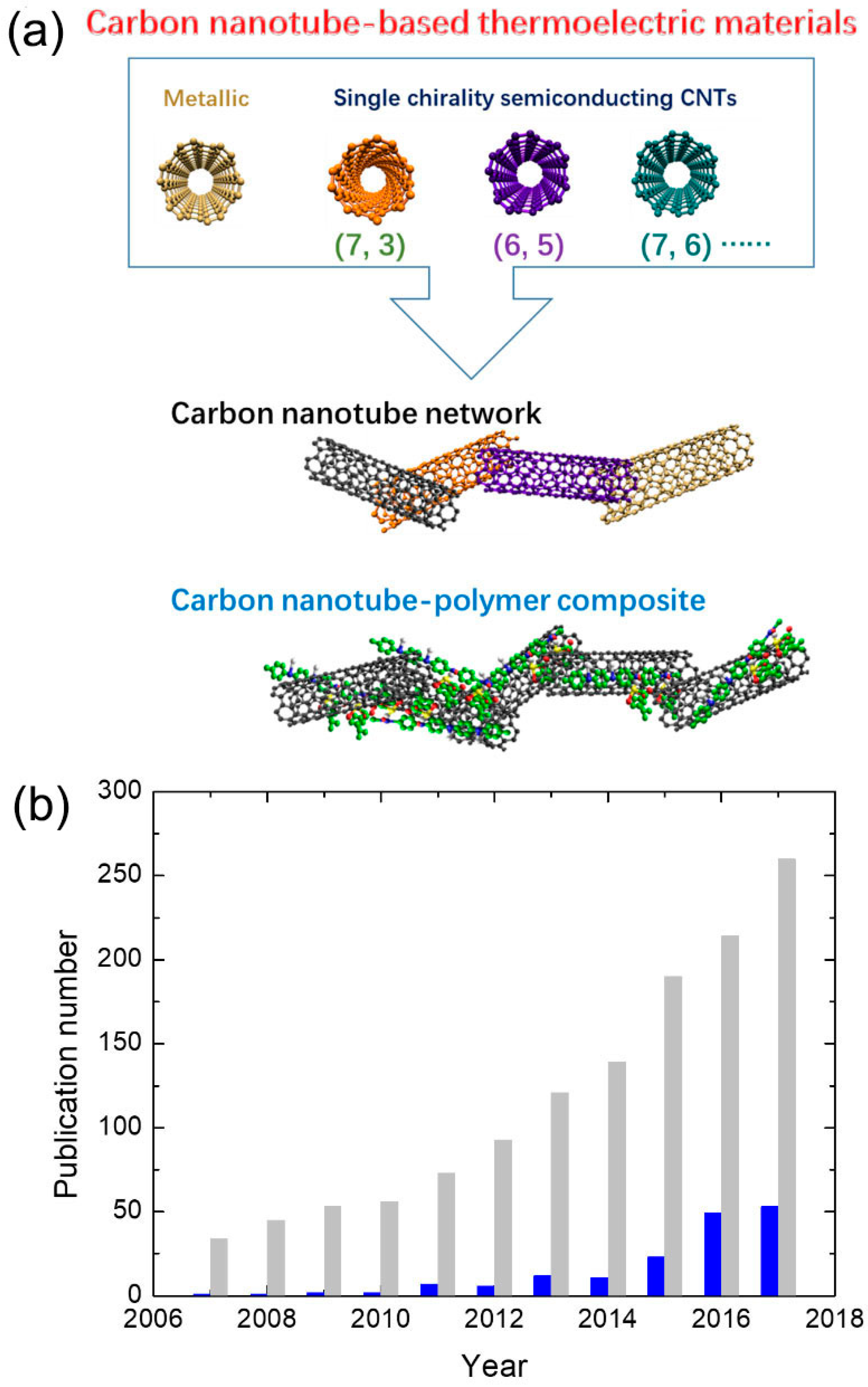
1. Introduction
2. Basic Description of the Three Key Parameters for TE Materials
3. TE Properties of CNTs
3.1. TE Properties of N-Type and P-Type CNTs
3.1.1. P-Type CNTs
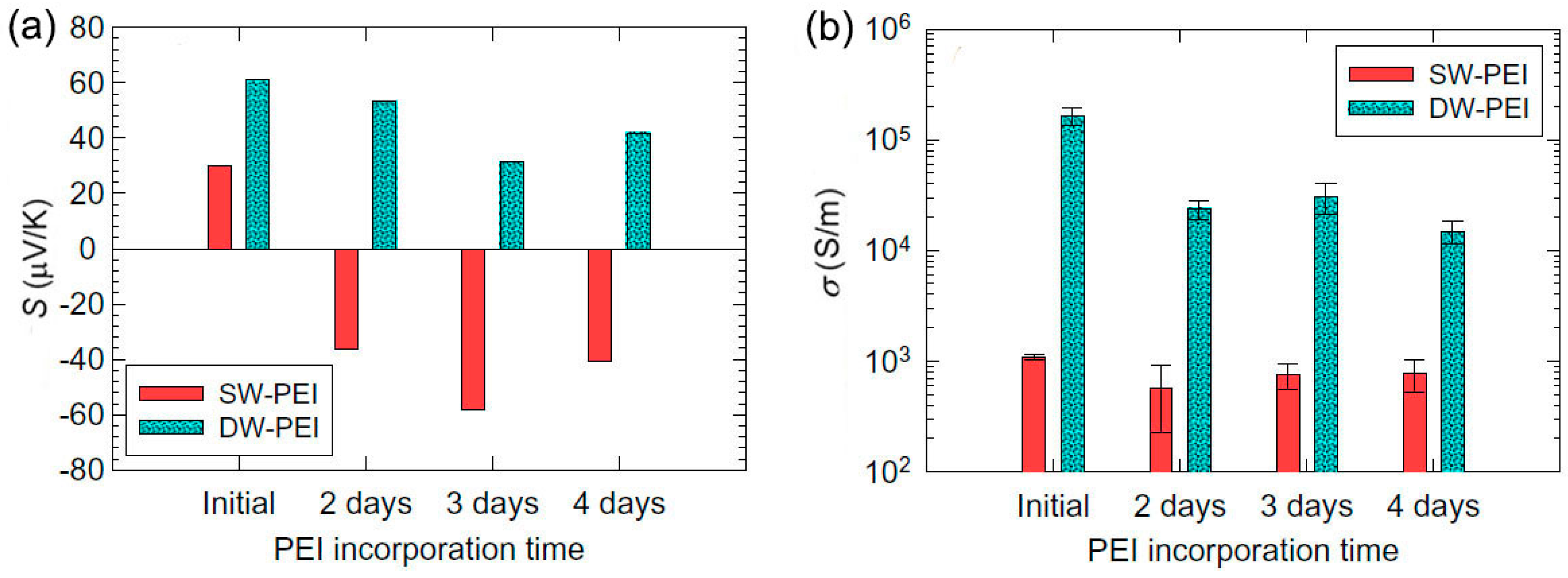
3.1.2. N-Type CNTs
3.1.3. CNTs-Based TE Devices
3.2. TE Performance of Semiconducting CNTs
4. CNT‒Polymer Composites
4.1. In Series and Parallel Models for Composites
4.2. TE Properties of CNT‒Polymer Composite
5. Conclusions
Author Contributions
Funding
Acknowledgments
Conflicts of Interest
References
- Zhu, T.; Liu, Y.; Fu, C.; Heremans, J.P.; Snyder, J.G.; Zhao, X. Compromise and synergy in high-efficiency thermoelectric materials. Adv. Mater. 2017, 29, 1605884. [Google Scholar] [CrossRef] [PubMed]
- He, J.; Tritt, T.M. Advances in thermoelectric materials research: Looking back and moving forward. Science 2017, 357, 1369. [Google Scholar] [CrossRef] [PubMed]
- Zhang, Q.H.; Huang, X.Y.; Bai, S.Q.; Shi, X.; Uher, C.; Chen, L.D. Thermoelectric devices for power generation: Recent progress and future challenges. Adv. Eng. Mater. 2016, 18, 194–213. [Google Scholar] [CrossRef]
- Bell, L.E. Cooling, heating, generating power, and recovering waste heat with thermoelectric systems. Science 2008, 321, 1457–1461. [Google Scholar] [CrossRef] [PubMed]
- Zebarjadi, M.; Esfarjani, K.; Dresselhaus, M.S.; Ren, Z.F.; Chen, G. Perspectives on thermoelectrics: From fundamentals to device applications. Energy Environ. Sci. 2012, 5, 5147–5162. [Google Scholar] [CrossRef]
- Yang, L.; Chen, Z.-G.; Dargusch, M.S.; Zou, J. High performance thermoelectric materials: Progress and their applications. Adv. Energy Mater. 2017, 8, 1701797. [Google Scholar] [CrossRef]
- Wang, C.; Niu, Y.; Jiang, J.; Chen, Y.; Tian, H.; Zhang, R.; Zhou, T.; Xia, J.; Pan, Y.; Wang, S. Hybrid thermoelectric battery electrode FeS2 study. Nano Energy 2018, 45, 432–438. [Google Scholar] [CrossRef]
- Zheng, Y.; Zeng, H.; Zhu, Q.; Xu, J. Recent advances in conducting poly(3,4-ethylenedioxythiophene): Polystyrene sulfonate hybrids for thermoelectric applications. J. Mater. Chem. C 2018, 6, 8858–8873. [Google Scholar] [CrossRef]
- Oh, J.Y.; Lee, J.H.; Han, S.W.; Chae, S.S.; Bae, E.J.; Kang, Y.H.; Choi, W.J.; Cho, S.Y.; Lee, J.O.; Baik, H.K.; et al. Chemically exfoliated transition metal dichalcogenide nanosheet-based wearable thermoelectric generators. Energy Environ. Sci. 2016, 9, 1696–1705. [Google Scholar] [CrossRef]
- Tan, G.; Zhao, L.D.; Kanatzidis, M.G. Rationally designing high-performance bulk thermoelectric materials. Chem. Rev. 2016, 116, 12123–12149. [Google Scholar] [CrossRef] [PubMed]
- Bahk, J.-H.; Fang, H.; Yazawa, K.; Shakouri, A. Flexible thermoelectric materials and device optimization for wearable energy harvesting. J. Mater. Chem. C 2015, 3, 10362–10374. [Google Scholar] [CrossRef]
- Chen, Y.; Zhao, Y.; Liang, Z. Solution processed organic thermoelectrics: Towards flexible thermoelectric modules. Energy Environ. Sci. 2015, 8, 401–422. [Google Scholar] [CrossRef]
- Wang, X.; Meng, F.; Tang, H.; Gao, Z.; Li, S.; Jin, S.; Jiang, Q.; Jiang, F.; Xu, J. Design and fabrication of low resistance palm-power generator based on flexible thermoelectric composite film. Synth. Met. 2018, 235, 42–48. [Google Scholar] [CrossRef]
- Wang, Y.; Zhang, S.M.; Deng, Y. Flexible low-grade energy utilization devices based on high-performance thermoelectric polyaniline/tellurium nanorod hybrid films. J. Mater. Chem. A 2016, 4, 3554–3559. [Google Scholar] [CrossRef]
- Wu, G.; Gao, C.; Chen, G.; Wang, X.; Wang, H. High-performance organic thermoelectric modules based on flexible films of a novel n-type single-walled carbon nanotube. J. Mater. Chem. A 2016, 4, 1–7. [Google Scholar] [CrossRef]
- Zhao, L.D.; Lo, S.H.; Zhang, Y.; Sun, H.; Tan, G.; Uher, C.; Wolverton, C.; Dravid, V.P.; Kanatzidis, M.G. Ultralow thermal conductivity and high thermoelectric figure of merit in SnSe crystals. Nature 2014, 508, 373–377. [Google Scholar] [CrossRef] [PubMed]
- Wu, H.J.; Zhao, L.D.; Zheng, F.S.; Wu, D.; Pei, Y.L.; Tong, X.; Kanatzidis, M.G.; He, J.Q. Broad temperature plateau for thermoelectric figure of merit ZT > 2 in phase-separated PbTe0.7s0.3. Nat. Commun. 2014, 5, 4515. [Google Scholar] [CrossRef] [PubMed]
- Venkatasubramanian, R.; Siivola, E.; Colpitts, T.; O’Quinn, B. Thin-film thermoelectric devices with high room-temperature figures of merit. Nature 2001, 413, 597–602. [Google Scholar] [CrossRef] [PubMed]
- Chen, Z.-G.; Shi, X.; Zhao, L.-D.; Zou, J. High-performance SnSe thermoelectric materials: Progress and future challenge. Prog. Mater. Sci. 2018, 97, 283–346. [Google Scholar] [CrossRef]
- Zhao, X.B.; Ji, X.H.; Zhang, Y.H.; Zhu, T.J.; Tu, J.P.; Zhang, X.B. Bismuth telluride nanotubes and the effects on the thermoelectric properties of nanotube-containing nanocomposites. Appl. Phys. Lett. 2005, 86, 062111. [Google Scholar] [CrossRef]
- Lee, H.J.; Anoop, G.; Lee, H.J.; Kim, C.; Park, J.-W.; Choi, J.; Kim, H.; Kim, Y.J.; Lee, E.J.; Lee, S.-G.; et al. Enhanced thermoelectric performance of PEDOT:PSS/PANI-CSA polymer multilayer structures. Energy Environ. Sci. 2016, 2806–2811. [Google Scholar] [CrossRef]
- Poudel, B.; Hao, Q.; Ma, Y.; Lan, Y.; Minnich, A.; Yu, B.; Yan, X.; Wang, D.; Muto, A.; Vashaee, D.; et al. High-thermoelectric performance of nanostructured bismuth antimony telluride bulk alloys. Science 2008, 320, 634–638. [Google Scholar] [CrossRef] [PubMed]
- Jiang, F.; Xu, J.; Lu, B.; Xie, Y.; Huang, R.; Li, L. Thermoelectric performance of Poly(3,4-ethylenedioxythiophene): Poly(styrenesulfonate). Chin. Phys. Lett. 2008, 25, 2202–2205. [Google Scholar]
- Yue, R.; Xu, J. Poly(3,4-ethylenedioxythiophene) as promising organic thermoelectric materials: A mini-review. Synth. Met. 2012, 162, 912–917. [Google Scholar] [CrossRef]
- Li, J.; Tang, X.; Li, H.; Yan, Y.; Zhang, Q. Synthesis and thermoelectric properties of hydrochloric acid-doped polyaniline. Synth. Met. 2010, 160, 1153–1158. [Google Scholar] [CrossRef]
- Zhu, Z.; Liu, C.; Jiang, F.; Xu, J.; Liu, E. Effective treatment methods on PEDOT:PSS to enhance its thermoelectric performance. Synth. Met 2017, 225, 31–40. [Google Scholar] [CrossRef]
- Park, T.; Park, C.; Kim, B.; Shin, H.; Kim, E. Flexible pedot electrodes with large thermoelectric power factors to generate electricity by the touch of fingertips. Energy Environ. Sci. 2013, 6, 788–792. [Google Scholar] [CrossRef]
- Singh, D.; Kutbee, A.T.; Ghoneim, M.T.; Hussain, A.M.; Hussain, M.M. Strain-induced rolled thin films for lightweight tubular thermoelectric generators. Adv. Mater. Technol. 2018, 3, 1700192. [Google Scholar] [CrossRef]
- Du, Y.; Cai, K.; Chen, S.; Wang, H.; Shen, S.Z.; Donelson, R.; Lin, T. Thermoelectric fabrics: Toward power generating clothing. Sci. Rep. 2015, 5, 6411. [Google Scholar] [CrossRef] [PubMed]
- Palumbiny, C.M.; Liu, F.; Russell, T.P.; Hexemer, A.; Wang, C.; Muller-Buschbaum, P. The crystallization of PEDOT:PSS polymeric electrodes probed in situ during printing. Adv. Mater. 2015, 27, 3391–3397. [Google Scholar] [CrossRef] [PubMed]
- See, K.C.; Feser, J.P.; Chen, C.E.; Majumdar, A.; Urban, J.J.; Segalman, R.A. Water-processable polymer-nanocrystal hybrids for thermoelectrics. Nano Lett. 2010, 10, 4664–4667. [Google Scholar] [CrossRef] [PubMed]
- Xiong, J.; Jiang, F.; Zhou, W.; Liu, C.; Xu, J. Highly electrical and thermoelectric properties of a PEDOT:SS thin-film via direct dilution–filtration. RSC Adv. 2015, 5, 60708–60712. [Google Scholar] [CrossRef]
- Kaloni, T.P.; Giesbrecht, P.K.; Schreckenbach, G.; Freund, M.S. Polythiophene: From fundamental perspectives to applications. Chem. Mater. 2017, 29, 10248–10283. [Google Scholar] [CrossRef]
- Cowen, L.M.; Atoyo, J.; Carnie, M.J.; Baran, D.; Schroeder, B.C. Review-organic materials for thermoelectric energy generation. ESC J. Solid State Sci. Technol. 2017, 6, N3080–N3088. [Google Scholar] [CrossRef]
- Ferhat, S.; Domain, C.; Vidal, J.; Noël, D.; Ratier, B.; Lucas, B. Organic thermoelectric devices based on a stable n-type nanocomposite printed on paper. Sustain. Energy Fuels 2018, 2, 199–208. [Google Scholar] [CrossRef]
- Cho, C.; Wallace, K.L.; Tzeng, P.; Hsu, J.-H.; Yu, C.; Grunlan, J.C. Outstanding low temperature thermoelectric power factor from completely organic thin films enabled by multidimensional conjugated nanomaterials. Adv. Energy Mater. 2016, 6, 1502168. [Google Scholar] [CrossRef]
- Shindo, T.; Nakatani, Y.; Oishi, T. Thermoelectric generating system for effective use of unutilized energy. Toshiba Rev. 2008, 63, 7–10. [Google Scholar]
- Wang, H.; Hsu, J.-H.; Yi, S.-I.; Kim, S.L.; Choi, K.; Yang, G.; Yu, C. Thermally driven large n-type voltage responses from hybrids of carbon nanotubes and poly(3,4-ethylenedioxythiophene) with tetrakis(dimethylamino)ethylene. Adv. Mater. 2015, 27, 6855–6861. [Google Scholar] [CrossRef] [PubMed]
- Li, C.; Jiang, F.; Liu, C.; Wang, W.; Li, X.; Wang, T.; Xu, J. A simple thermoelectric device based on inorganic/organic composite thin film for energy harvesting. Chem. Eng. J. 2017, 320, 201–210. [Google Scholar] [CrossRef]
- Bubnova, O.; Khan, Z.U.; Malti, A.; Braun, S.; Fahlman, M.; Berggren, M.; Crispin, X. Optimization of the thermoelectric figure of merit in the conducting polymer poly(3,4-ethylenedioxythiophene). Nat. Mater. 2011, 10, 429–433. [Google Scholar] [CrossRef] [PubMed]
- Kim, G.H.; Shao, L.; Zhang, K.; Pipe, K.P. Engineered doping of organic semiconductors for enhanced thermoelectric efficiency. Nat. Mater. 2013, 12, 719–723. [Google Scholar] [CrossRef] [PubMed]
- Song, H.; Liu, C.; Xu, J.; Jiang, Q.; Shi, H. Fabrication of a layered nanostructure PEDOT:PSS/SWCNTs composite and its thermoelectric performance. RSC Adv. 2013, 3, 22065–22071. [Google Scholar] [CrossRef]
- Bubnova, O.; Crispin, X. Towards polymer-based organic thermoelectric generators. Energy Environ. Sci. 2012, 5, 9345–9362. [Google Scholar] [CrossRef]
- Poehler, T.O.; Katz, H.E. Prospects for polymer-based thermoelectrics: State of the art and theoretical analysis. Energy Environ. Sci. 2012, 5, 8110–8115. [Google Scholar] [CrossRef]
- Kroon, R.; Mengistie, D.A.; Kiefer, D.; Hynynen, J.; Ryan, J.D.; Yu, L.; Muller, C. Thermoelectric plastics: From design to synthesis, processing and structure-property relationships. Chem. Soc. Rev. 2016, 45, 6147–6164. [Google Scholar] [CrossRef] [PubMed]
- Zhang, Q.; Sun, Y.; Xu, W.; Zhu, D. Organic thermoelectric materials: Emerging green energy materials converting heat to electricity directly and efficiently. Adv. Mater. 2014, 26, 6829–6851. [Google Scholar] [CrossRef] [PubMed]
- Blackburn, J.L.; Ferguson, A.J.; Cho, C.; Grunlan, J.C. Carbon-nanotube-based thermoelectric materials and devices. Adv. Mater. 2018, 30, 1704386. [Google Scholar] [CrossRef] [PubMed]
- Wang, X.; Meng, F.; Wang, T.; Li, C.; Tang, H.; Gao, Z.; Li, S.; Jiang, F.; Xu, J. High performance of PEDOT:PSS/SiC-NWs hybrid thermoelectric thin film for energy harvesting. J. Alloys Compd. 2018, 734, 121–129. [Google Scholar] [CrossRef]
- Xu, K.; Chen, G.; Qiu, D. Convenient construction of poly(3,4-ethylenedioxythiophene)-graphene pie-like structure with enhanced thermoelectric performance. J. Mate. Chem. A 2013, 1, 12395–12399. [Google Scholar] [CrossRef]
- Rowe, D.M. Thermoelectric Handbook: Macro to Nano; CRC Press: Boca Raton, FL, USA, 2005. [Google Scholar]
- MacDonald, D.K.C. Thermoelectricity: An Introduction to the Principles; Dover Publications: Mineola, NY, USA, 2006. [Google Scholar]
- Sung, J.H.; Heo, H.; Hwang, I.; Lim, M.; Lee, D.; Kang, K.; Choi, H.C.; Park, J.H.; Jhi, S.H.; Jo, M.H. Atomic layer-by-layer thermoelectric conversion in topological insulator bismuth/antimony tellurides. Nano Lett. 2014, 14, 4030–4035. [Google Scholar] [CrossRef] [PubMed]
- Bubnova, O.; Khan, Z.U.; Wang, H.; Braun, S.; Evans, D.R.; Fabretto, M.; Hojati-Talemi, P.; Dagnelund, D.; Arlin, J.B.; Geerts, Y.H.; et al. Semi-metallic polymers. Nat. Mater. 2014, 13, 190–194. [Google Scholar] [CrossRef] [PubMed]
- Shi, H.; Liu, C.; Jiang, Q.; Xu, J. Effective approaches to improve the electrical conductivity of pedot:Pss: A review. Adv. Electron. Mater. 2015, 1, 1500017. [Google Scholar] [CrossRef]
- Sun, J.; Yeh, M.L.; Jung, B.J.; Zhang, B.; Feser, J.; Majumdar, A.; Katz, H.E. Simultaneous increase in Seebeck coefficient and conductivity in a doped poly(alkylthiophene) blend with defined density of states. Macromolecules 2010, 43, 2897–2903. [Google Scholar] [CrossRef]
- Shi, W.; Qu, S.; Chen, H.; Chen, Y.; Yao, Q.; Chen, L. One-step synthesis and enhanced thermoelectric properties of polymer-quantum dot composite films. Angew. Chem. Int. Ed. 2018, 57, 8037–8042. [Google Scholar] [CrossRef] [PubMed]
- Tseng, F.; Li, S.; Wu, C.; Pan, Y.; Li, L. Thermoelectric and mechanical properties of ZnSb/SiC nanocomposites. J. Mater. Sci. 2016, 51, 5271–5280. [Google Scholar] [CrossRef]
- Chen, G. Thermal conductivity and ballistic-phonon transport in the cross-plane direction of superlattices. Phys. Rev. B 1998, 57, 14958. [Google Scholar] [CrossRef]
- Kittel, C. Introduction to Solid State Physics; Wiley: Hoboken, NY, USA, 2004. [Google Scholar]
- Pei, Y.; Wang, H.; Snyder, G.J. Band engineering of thermoelectric materials. Adv. Mater. 2012, 24, 6125–6135. [Google Scholar] [CrossRef] [PubMed]
- Tan, D.; Zhao, J.; Gao, C.; Wang, H.; Chen, G.; Shi, D. Carbon nanoparticle hybrid aerogels: 3d double-interconnected network porous microstructure, thermoelectric, and solvent-removal functions. ACS Appl. Mater. Interfaces 2017, 9, 21820–21828. [Google Scholar] [CrossRef] [PubMed]
- Iijima, S. Helical microtubules of graphitic carbon. Nature 1991, 354, 56–58. [Google Scholar] [CrossRef]
- Hicks, L.D.; Dresselhaus, M.S. Thermoelectric figure of merit of a one-dimensional conductor. Phys. Rev. B 1993, 47, 16631–16634. [Google Scholar] [CrossRef]
- Landolt, H.H.; Bornstein, R. Numerical Data and Functional Relationships in Science and Technology; Springer: Berlin, Germany, 1983; pp. 272–278. [Google Scholar]
- Tian, M.; Li, F.; Chen, L.; Mao, Z.; Zhang, Y. Thermoelectric power behavior in carbon nanotubule bundles from 4.2 to 300 k. Phys. Rev. B 1998, 58, 1166–1168. [Google Scholar] [CrossRef]
- Grigorian, L.; Sumanasekera, G.U.; Loper, A.L.; Fang, S.L.; Allen, J.L.; Eklund, P.C. Giant thermopower in carbon nanotubes: A one-dimensional kondo system. Phys. Rev. B 1999, 60, R11309–R11312. [Google Scholar] [CrossRef]
- Hone, J.; Ellwood, I.; Muno, M.; Mizel, A.; Cohen, M.L.; Zettl, A.; Rinzler, A.G.; Smalley, R.E. Thermoelectric power of single-walled carbon nanotubes. Phys. Rev. Lett. 1998, 80, 1042–1045. [Google Scholar] [CrossRef]
- Collins, P.G.; Bradley, K.; Ishigami, M.; Zettl, A. Extreme oxygen sensitivity of electronic properties of carbon nanotubes. Science 2000, 287, 1801–1804. [Google Scholar] [CrossRef] [PubMed]
- Kong, J.; Franklin, N.R.; Zhou, C.; Chapline, M.G.; Peng, S.; Cho, K.; Dai, H. Nanotube molecular wires as chemical sensors. Science 2000, 287, 622–625. [Google Scholar] [CrossRef] [PubMed]
- Ryu, Y.; Yin, L.; Yu, C. Dramatic electrical conductivity improvement of carbon nanotube networks by simultaneous de-bundling and hole-doping with chlorosulfonic acid. J. Mater. Chem. 2012, 22, 6959–6964. [Google Scholar] [CrossRef]
- Kim, K.K.; Bae, J.J.; Park, H.K.; Kim, S.M.; Geng, H.-Z.; Park, K.A.; Shin, H.-J.; Yoon, S.-M.; Benayad, A.; Choi, J.-Y.; et al. Fermi level engineering of single-walled carbon nanotubes by AuCl3 doping. J. Am. Chem. Soc. 2008, 130, 12757–12761. [Google Scholar] [CrossRef] [PubMed]
- Erickson, K.J.; Leonard, F.; Stavila, V.; Foster, M.E.; Spataru, C.D.; Jones, R.E.; Foley, B.M.; Hopkins, P.E.; Allendorf, M.D.; Talin, A.A. Thin film thermoelectric metal-organic framework with high seebeck coefficient and low thermal conductivity. Adv. Mater. 2015, 27, 3453–3459. [Google Scholar] [CrossRef] [PubMed]
- Ramesh, S.; Ericson, L.M.; Davis, V.A.; Saini, R.K.; Kittrell, C.; Pasquali, M.; Billups, W.E.; Adams, W.W.; Hauge, R.H.; Smalley, R.E. Dissolution of pristine single walled carbon nanotubes in superacids by direct protonation. J. Phys. Chem. B 2004, 108, 8794–8798. [Google Scholar] [CrossRef]
- Zhao, W.; Fan, S.; Xiao, N.; Liu, D.; Tay, Y.Y.; Yu, C.; Sim, D.; Hng, H.H.; Zhang, Q.; Boey, F.; et al. Flexible carbon nanotube papers with improved thermoelectric properties. Energy Environ. Sci. 2012, 5, 5364–5369. [Google Scholar] [CrossRef]
- Ryu, Y.; Freeman, D.; Yu, C. High electrical conductivity and n-type thermopower from double-/single-wall carbon nanotubes by manipulating charge interactions between nanotubes and organic/inorganic nanomaterials. Carbon 2011, 49, 4745–4751. [Google Scholar] [CrossRef]
- Cho, C.; Culebras, M.; Wallace, K.L.; Song, Y.; Holder, K.; Hsu, J.-H.; Yu, C.; Grunlan, J.C. Stable n-type thermoelectric multilayer thin films with high power factor from carbonaceous nanofillers. Nano Energy 2016, 28, 426–432. [Google Scholar] [CrossRef]
- Shim, M.; Javey, A.; Shi Kam, N.W.; Dai, H. Polymer functionalization for air-stable n-type carbon nanotube field-effect transistors. J. Am. Chem. Soc. 2001, 123, 11512–11513. [Google Scholar] [CrossRef] [PubMed]
- Zhou, Y.; Gaur, A.; Hur, S.-H.; Kocabas, C.; Meitl, M.A.; Shim, M.; Rogers, J.A. P-channel, n-channel thin film transistors and p−n diodes based on single wall carbon nanotube networks. Nano Lett. 2004, 4, 2031–2035. [Google Scholar] [CrossRef]
- Siddons, G.P.; Merchin, D.; Back, J.H.; Jeong, J.K.; Shim, M. Highly efficient gating and doping of carbon nanotubes with polymer electrolytes. Nano Lett. 2004, 4, 927–931. [Google Scholar] [CrossRef]
- Kim, S.M.; Jang, J.H.; Kim, K.K.; Park, H.K.; Bae, J.J.; Yu, W.J.; Lee, I.H.; Kim, G.; Loc, D.D.; Kim, U.J.; et al. Reduction-controlled viologen in bisolvent as an environmentally stable n-type dopant for carbon nanotubes. J. Am. Chem. Soc. 2009, 131, 327–331. [Google Scholar] [CrossRef] [PubMed]
- Wu, G.; Zhang, Z.-G.; Li, Y.; Gao, C.; Wang, X.; Chen, G. Exploring high-performance n-type thermoelectric composites using amino-substituted rylene dimides and carbon nanotubes. ACS Nano 2017, 11, 5746–5752. [Google Scholar] [CrossRef] [PubMed]
- An, C.J.; Kang, Y.H.; Song, H.; Jeong, Y.; Cho, S.Y. High-performance flexible thermoelectric generator by control of electronic structure of directly spun carbon nanotube webs with various molecular dopants. J. Mater. Chem. A 2017, 5, 15631–15639. [Google Scholar] [CrossRef]
- Biswas, C.; Lee, S.Y.; Ly, T.H.; Ghosh, A.; Dang, Q.N.; Lee, Y.H. Chemically doped random network carbon nanotube p–n junction diode for rectifier. ACS Nano 2011, 5, 9817–9823. [Google Scholar] [CrossRef] [PubMed]
- Yu, C.; Murali, A.; Choi, K.; Ryu, Y. Air-stable fabric thermoelectric modules made of n- and p-type carbon nanotubes. Energy Environ. Sci. 2012, 5, 9481–9486. [Google Scholar] [CrossRef]
- Kim, S.L.; Choi, K.; Tazebay, A.; Yu, C. Flexible power fabrics made of carbon nanotubes for harvesting thermoelectricity. ACS Nano 2014, 8, 2377–2386. [Google Scholar] [CrossRef] [PubMed]
- Zhou, W.; Fan, Q.; Zhang, Q.; Cai, L.; Li, K.; Gu, X.; Yang, F.; Zhang, N.; Wang, Y.; Liu, H.; et al. High-performance and compact-designed flexible thermoelectric modules enabled by a reticulate carbon nanotube architecture. Nat. Commun. 2017, 8, 14886. [Google Scholar] [CrossRef] [PubMed]
- Ito, M.; Koizumi, T.; Kojima, H.; Saito, T.; Nakamura, M. From materials to device design of a thermoelectric fabric for wearable energy harvesters. J. Mater.Chem. A 2017, 5, 12068–12072. [Google Scholar] [CrossRef]
- Saito, T.; Ohshima, S.; Okazaki, T.; Ohmori, S.; Yumura, M.; Iijima, S. Selective diameter control of single-walled carbon nanotubes in the gas-phase synthesis. J. Nanosci. Nanotechnol. 2008, 8, 6153–6157. [Google Scholar] [CrossRef] [PubMed]
- Dresselhaus, M.S.; Chen, G.; Tang, M.Y.; Yang, R.G.; Lee, H.; Wang, D.Z.; Ren, Z.F.; Fleurial, J.P.; Gogna, P. New directions for low-dimensional thermoelectric materials. Adv. Mater. 2007, 19, 1043–1053. [Google Scholar] [CrossRef]
- Hicks, L.D.; Harman, T.C.; Sun, X.; Dresselhaus, M.S. Experimental study of the effect of quantum-well structures on the thermoelectric figure of merit. Phys. Rev. B 1996, 53, R10493–R10496. [Google Scholar] [CrossRef]
- Hung, N.T.; Nugraha, A.R.T.; Hasdeo, E.H.; Dresselhaus, M.S.; Saito, R. Diameter dependence of thermoelectric power of semiconducting carbon nanotubes. Phys. Rev. B 2015, 92, 165426. [Google Scholar] [CrossRef]
- Samsonidze, G.G.; Saito, R.; Kobayashi, N.; Gruneis, A.; Jiang, J.; Jorio, A.; Chou, S.G.; Dresselhaus, G.; Dresselhaus, M.S. Family behavior of the optical transition energies in single-wall carbon nanotubes of smaller diameters. Appl. Phys. Lett. 2004, 85, 5703–5705. [Google Scholar] [CrossRef]
- Yanagi, K.; Kanda, S.; Oshima, Y.; Kitamura, Y.; Kawai, H.; Yamamoto, T.; Takenobu, T.; Nakai, Y.; Maniwa, Y. Tuning of the thermoelectric properties of one-dimensional material networks by electric double layer techniques using ionic liquids. Nano Lett. 2014, 14, 6437–6442. [Google Scholar] [CrossRef] [PubMed]
- Javey, A.; Guo, J.; Paulsson, M.; Wang, Q.; Mann, D.; Lundstrom, M.; Dai, H. High-field quasiballistic transport in short carbon nanotubes. Phys. Rev. Lett. 2004, 92, 106804. [Google Scholar] [CrossRef] [PubMed]
- Nakai, Y.; Honda, K.; Yanagi, K.; Kataura, H.; Kato, T.; Yamamoto, T.; Maniwa, Y. Giant seebeck coefficient in semiconducting single-wall carbon nanotube film. Appl. Phys. Express 2014, 7, 025103. [Google Scholar] [CrossRef]
- Piao, M.; Joo, M.-K.; Na, J.; Kim, Y.-J.; Mouis, M.; Ghibaudo, G.; Roth, S.; Kim, W.-Y.; Jang, H.-K.; Kennedy, G.P.; et al. Effect of intertube junctions on the thermoelectric power of monodispersed single walled carbon nanotube networks. J. Phys. Chem. C 2014, 118, 26454–26461. [Google Scholar] [CrossRef]
- Tu, X.; Manohar, S.; Jagota, A.; Zheng, M. DNA sequence motifs for structure-specific recognition and separation of carbon nanotubes. Nature 2009, 460, 250–253. [Google Scholar] [CrossRef] [PubMed]
- Arnold, M.S.; Green, A.A.; Hulvat, J.F.; Stupp, S.I.; Hersam, M.C. Sorting carbon nanotubes by electronic structure using density differentiation. Nat. Nano 2006, 1, 60–65. [Google Scholar] [CrossRef] [PubMed]
- Nish, A.; Hwang, J.-Y.; Doig, J.; Nicholas, R.J. Highly selective dispersion of single-walled carbon nanotubes using aromatic polymers. Nat. Nanotechnol. 2007, 2, 640–646. [Google Scholar] [CrossRef] [PubMed]
- Zhang, S.; Kang, L.; Wang, X.; Tong, L.; Yang, L.; Wang, Z.; Qi, K.; Deng, S.; Li, Q.; Bai, X.; et al. Arrays of horizontal carbon nanotubes of controlled chirality grown using designed catalysts. Nature 2017, 543, 234–238. [Google Scholar] [CrossRef] [PubMed]
- Avery, A.D.; Zhou, B.H.; Lee, J.; Lee, E.-S.; Miller, E.M.; Ihly, R.; Wesenberg, D.; Mistry, K.S.; Guillot, S.L.; Zink, B.L.; et al. Tailored semiconducting carbon nanotube networks with enhanced thermoelectric properties. Nat. Energy 2016, 1, 16033. [Google Scholar] [CrossRef]
- MacLeod, B.A.; Stanton, N.J.; Gould, I.E.; Wesenberg, D.; Ihly, R.; Owczarczyk, Z.R.; Hurst, K.E.; Fewox, C.S.; Folmar, C.N.; Holman Hughes, K.; et al. Large n- and p-type thermoelectric power factors from doped semiconducting single-walled carbon nanotube thin films. Energy Environ. Sci. 2017, 10, 2168–2179. [Google Scholar] [CrossRef]
- Xiong, J.; Jiang, F.; Shi, H.; Xu, J.; Liu, C.; Zhou, W.; Jiang, Q.; Zhu, Z.; Hu, Y. Liquid exfoliated graphene as dopant for improving the thermoelectric power factor of conductive PEDOT:PSS nanofilm with hydrazine treatment. ACS Appl. Mater. Interfaces 2015, 7, 14917–14925. [Google Scholar] [CrossRef] [PubMed]
- Wang, L.; Zhang, Z.; Geng, L.; Yuan, T.; Liu, Y.; Guo, J.; Fang, L.; Qiu, J.; Wang, S. Solution-printable fullerene/TiS2 organic/inorganic hybrids for high-performance flexible n-type thermoelectrics. Energy Environ. Sci. 2018, 11, 1307–1317. [Google Scholar] [CrossRef]
- Zhang, B.; Sun, J.; Katz, H.E.; Fang, F.; Opila, R.L. Promising thermoelectric properties of commercial PEDOT:PSS materials and their Bi2Te3 powder composites. ACS Appl. Mater. Interfaces 2010, 2, 3170–3178. [Google Scholar] [CrossRef] [PubMed]
- Sahu, A.; Russ, B.; Su, N.C.; Forster, J.D.; Zhou, P.; Cho, E.S.; Ercius, P.; Coates, N.E.; Segalman, R.A.; Urban, J.J. Bottom-up design of de novo thermoelectric hybrid materials using chalcogenide resurfacing. J. Mater. Chem. A 2017, 5, 3346–3357. [Google Scholar] [CrossRef]
- Progelhof, R.C.; Throne, J.L.; Ruetsch, R.R. Methods for predicting the thermal conductivity of composite systems: A review. Polym. Eng. Sci. 1976, 16, 615–625. [Google Scholar] [CrossRef]
- Lee, D.; Sayed, S.Y.; Lee, S.; Kuryak, C.A.; Zhou, J.; Chen, G.; Shao-Horn, Y. Quantitative analyses of enhanced thermoelectric properties of modulation-doped PEDOT:PSS/undoped Si (001) nanoscale heterostructures. Nanoscale 2016, 8, 19754–19760. [Google Scholar] [CrossRef] [PubMed]
- Ju, H.; Kim, J. Chemically exfoliated snse nanosheets and their SnSe/poly(3,4-ethylenedioxythiophene): Poly(styrenesulfonate) composite films for polymer based thermoelectric applications. ACS Nano 2016, 10, 5730–5739. [Google Scholar] [CrossRef] [PubMed]
- Qu, S.; Yao, Q.; Wang, L.; Hua, J.; Chen, L. A novel hydrophilic pyridinium salt polymer/swcnts composite film for high thermoelectric performance. Polymer 2018, 136, 149–156. [Google Scholar] [CrossRef]
- Gao, C.; Chen, G. A new strategy to construct thermoelectric composites of swcnts and poly-schiff bases with 1,4-diazabuta-1,3-diene structures acting as bidentate-chelating units. J. Mater. Chem. A 2016, 4, 11299–11306. [Google Scholar] [CrossRef]
- Fan, W.; Guo, C.-Y.; Chen, G. Flexible films of poly(3,4-ethylenedioxythiophene)/carbon nanotube thermoelectric composites prepared by dynamic 3-phase interfacial electropolymerization and subsequent physical mixing. J. Mater. Chem. A 2018, 6, 12275–12280. [Google Scholar] [CrossRef]
- Hu, M.; Yu, D.; Wei, J. Thermal conductivity determination of small polymer samples by differential scanning calorimetry. Polym. Test. 2007, 26, 333–337. [Google Scholar] [CrossRef]
- Yu, C.; Kim, Y.S.; Kim, D.; Grunlan, J.C. Thermoelectric behavior of segregated-network polymer nanocomposites. Nano Lett. 2008, 8, 4428–4432. [Google Scholar] [CrossRef] [PubMed]
- Jiang, F.; Liu, C.; Xu, J. The evolution of organic thermoelectric materials based on conducting pedot. Chin. Sci. Bull. 2017, 62, 2063–2076. [Google Scholar] [CrossRef]
- Kim, D.; Kim, Y.; Choi, K.; Grunlan, J.C.; Yu, C. Improved thermoelectric behavior of nanotube-filled polymer composites with poly(3,4-ethylenedioxythiophene) poly(styrenesulfonate). ACS Nano 2010, 4, 513–523. [Google Scholar] [CrossRef] [PubMed]
- Yu, C.; Choi, K.; Yin, L.; Grunlan, J.C. Light-weight flexible carbon nanotube based organic composites with large thermoelectric power factors. ACS Nano 2011, 5, 7885–7892. [Google Scholar] [CrossRef] [PubMed]
- Choi, J.; Lee, K.; Park, C.R.; Kim, H. Enhanced thermopower in flexible tellurium nanowire films doped using single-walled carbon nanotubes with a rationally designed work function. Carbon 2015, 94, 577–584. [Google Scholar] [CrossRef]
- Yao, Q.; Wang, Q.; Wang, L.; Chen, L. Abnormally enhanced thermoelectric transport properties of SWCNT/PANI hybrid films by the strengthened PANI molecular ordering. Energy Environ. Sci. 2014, 7, 3801–3807. [Google Scholar] [CrossRef]
- Hsu, J.-H.; Choi, W.; Yang, G.; Yu, C. Origin of unusual thermoelectric transport behaviors in carbon nanotube filled polymer composites after solvent/acid treatments. Org. Electron. 2017, 45, 182–189. [Google Scholar] [CrossRef]
- Wang, H.; Yi, S.-I.; Pu, X.; Yu, C. Simultaneously improving electrical conductivity and thermopower of polyaniline composites by utilizing carbon nanotubes as high mobility conduits. ACS Appl. Mater. Interfaces 2015, 7, 9589–9597. [Google Scholar] [CrossRef] [PubMed]
- Wang, H.; Yi, S.-I.; Yu, C. Engineering electrical transport at the interface of conjugated carbon structures to improve thermoelectric properties of their composites. Polymer 2016, 97, 487–495. [Google Scholar] [CrossRef]
- Wang, X.; Meng, F.; Jiang, Q.; Zhou, W.; Jiang, F.; Wang, T.; Li, X.; Li, S.; Lin, Y.; Xu, J. Simple layer-by-layer assembly method for simultaneously enhanced electrical conductivity and thermopower of PEDOT:PSS/ce-MoS2 heterostructure films. ACS Appl. Energy Mater. 2018, 1, 3123–3133. [Google Scholar] [CrossRef]
- Liang, Z.; Boland, M.J.; Butrouna, K.; Strachan, D.R.; Graham, K.R. Increased power factors of organic-inorganic nanocomposite thermoelectric materials and the role of energy filtering. J. Mate. Chem. A 2017, 5, 15891–15900. [Google Scholar] [CrossRef]
- Wang, X.; Meng, F.; Tang, H.; Gao, Z.; Li, S.; Jiang, F.; Xu, J. An effective dual-solvent treatment for improving the thermoelectric property of PEDOT:PSS with white graphene. J. Mater. Sci. 2017, 52, 9806–9818. [Google Scholar] [CrossRef]
- Zhao, W.; Liu, Z.; Sun, Z.; Zhang, Q.; Wei, P.; Mu, X.; Zhou, H.; Li, C.; Ma, S.; He, D.; et al. Superparamagnetic enhancement of thermoelectric performance. Nature 2017, 549, 247–251. [Google Scholar] [CrossRef] [PubMed]
- Coates, N.E.; Yee, S.K.; McCulloch, B.; See, K.C.; Majumdar, A.; Segalman, R.A.; Urban, J.J. Effect of interfacial properties on polymer-nanocrystal thermoelectric transport. Adv. Mater. 2013, 25, 1629–1633. [Google Scholar] [CrossRef] [PubMed]
- Xiong, S.; Yin, S.; Wang, Y.; Kong, Z.; Lan, J.; Zhang, R.; Gong, M.; Wu, B.; Chu, J.; Wang, X. Organic/inorganic electrochromic nanocomposites with various interfacial interactions: A review. Mater. Sci. Eng. B 2017, 221, 41–53. [Google Scholar] [CrossRef]
- Song, H.; Cai, K. Preparation and properties of PEDOT:PSS/Te nanorod composite films for flexible thermoelectric power generator. Energy 2017, 125, 519–525. [Google Scholar] [CrossRef]


| Materials | Electrical Conductivity [S/cm] | Seebeck Coefficient [μV/K] | Power Factor [μW/m K2] | Ref. |
|---|---|---|---|---|
| DWNT-CSA | ~1.7 × 10⁴ | ~18 | 550.80 | [70] |
| DWNT-NMP | ~1500 | ~55 | 453.75 | [70] |
| DWNT-SDBS | ~2400 | ~36 | 311.04 | [70] |
| ASWNT-CSA | ~3100 | ~28 | 243.04 | [70] |
| ASWNT-NMP | ~500 | ~40 | 80 | [70] |
| ASWNT-SDBS | ~700 | ~24 | 40.32 | [70] |
| Materials | Electrical Conductivity [S cm−1] | Seebeck Coefficient [μV K−1] | Power Factor [μW m−1 K−2] | Ref. |
|---|---|---|---|---|
| SW-PEI | 10 | −58 | 3.4 | [75] |
| DWNT-PEI/graphene-PVP | 297 | −80 | 190 | [76] |
| SWCNT-PDINE | 500 | −47.3 | 112 ± 8 | [81] |
| SWCNT-NDINE | 446 | −55 | 135 ± 14 | [81] |
| Materials | Electrical Conductivity [S cm−1] | Seebeck Coefficient [μV K−1] | Power Factor [μW m−1 K−2] | Thermal Conductivity [W m−1 K−1] | ZT | Ref. |
|---|---|---|---|---|---|---|
| Hydrophilic pyridinium salt polymer/SWCNTs | 159 | 63.3 | 46.4 | - | - | [110] |
| Poly-Schiff base/SWCNT | 411.8 ± 18.7 | 43.4 ± 0.7 | 77.7 ± 5.8 | - | - | [111] |
| PEDOT:SWCNT | 1444.5 ± 86.9 | 53.9 ± 2.9 | 253.7 ± 10.4 | - | - | [112] |
| Segregated-network CNT−polymer | 48 | 38 | 6.9 | 0.34 | 0.006 | [114] |
| CNT‒PEDOT:PSS | 400 | 18.3 | 13.4 | 0.2–0.4 | 0.02 | [116] |
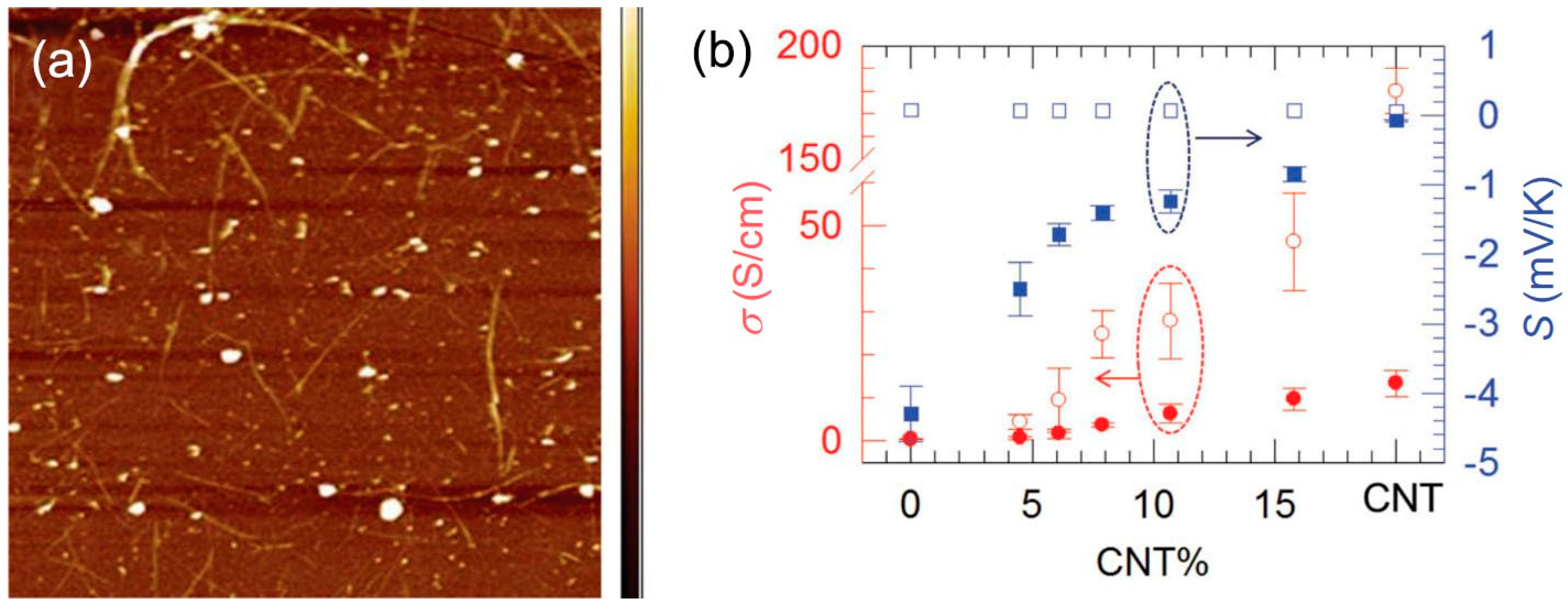
| SWNT/PANI | 769 | 65 | 176 | 0.43 | 0.12 | [119] |
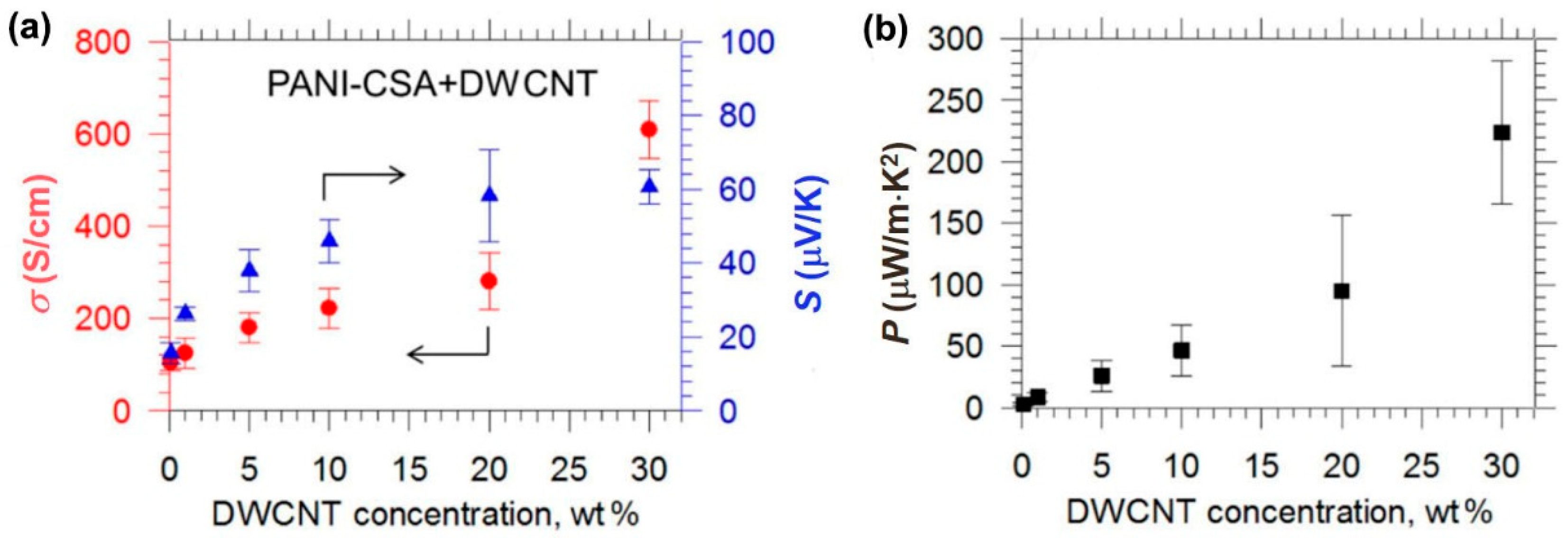
| CNT/PANI‒CSA | 610 | 61 | 220 | - | - | [121] |
© 2018 by the authors. Licensee MDPI, Basel, Switzerland. This article is an open access article distributed under the terms and conditions of the Creative Commons Attribution (CC BY) license (http://creativecommons.org/licenses/by/4.0/).
Share and Cite
Wang, X.; Wang, H.; Liu, B. Carbon Nanotube-Based Organic Thermoelectric Materials for Energy Harvesting. Polymers 2018, 10, 1196. https://doi.org/10.3390/polym10111196
Wang X, Wang H, Liu B. Carbon Nanotube-Based Organic Thermoelectric Materials for Energy Harvesting. Polymers. 2018; 10(11):1196. https://doi.org/10.3390/polym10111196
Chicago/Turabian StyleWang, Xiaodong, Hong Wang, and Bing Liu. 2018. "Carbon Nanotube-Based Organic Thermoelectric Materials for Energy Harvesting" Polymers 10, no. 11: 1196. https://doi.org/10.3390/polym10111196
APA StyleWang, X., Wang, H., & Liu, B. (2018). Carbon Nanotube-Based Organic Thermoelectric Materials for Energy Harvesting. Polymers, 10(11), 1196. https://doi.org/10.3390/polym10111196