The Influence of Fiber Cross-Section on Fabric Far-Infrared Properties


Abstract
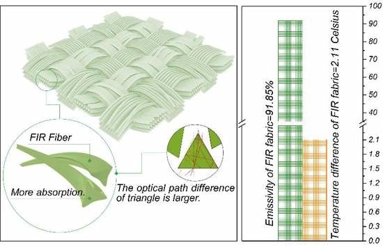
:
1. Introduction
2. Experimental Section
2.1. Materials
2.2. Preparation of Fabrics
2.3. Fabrics Characterization
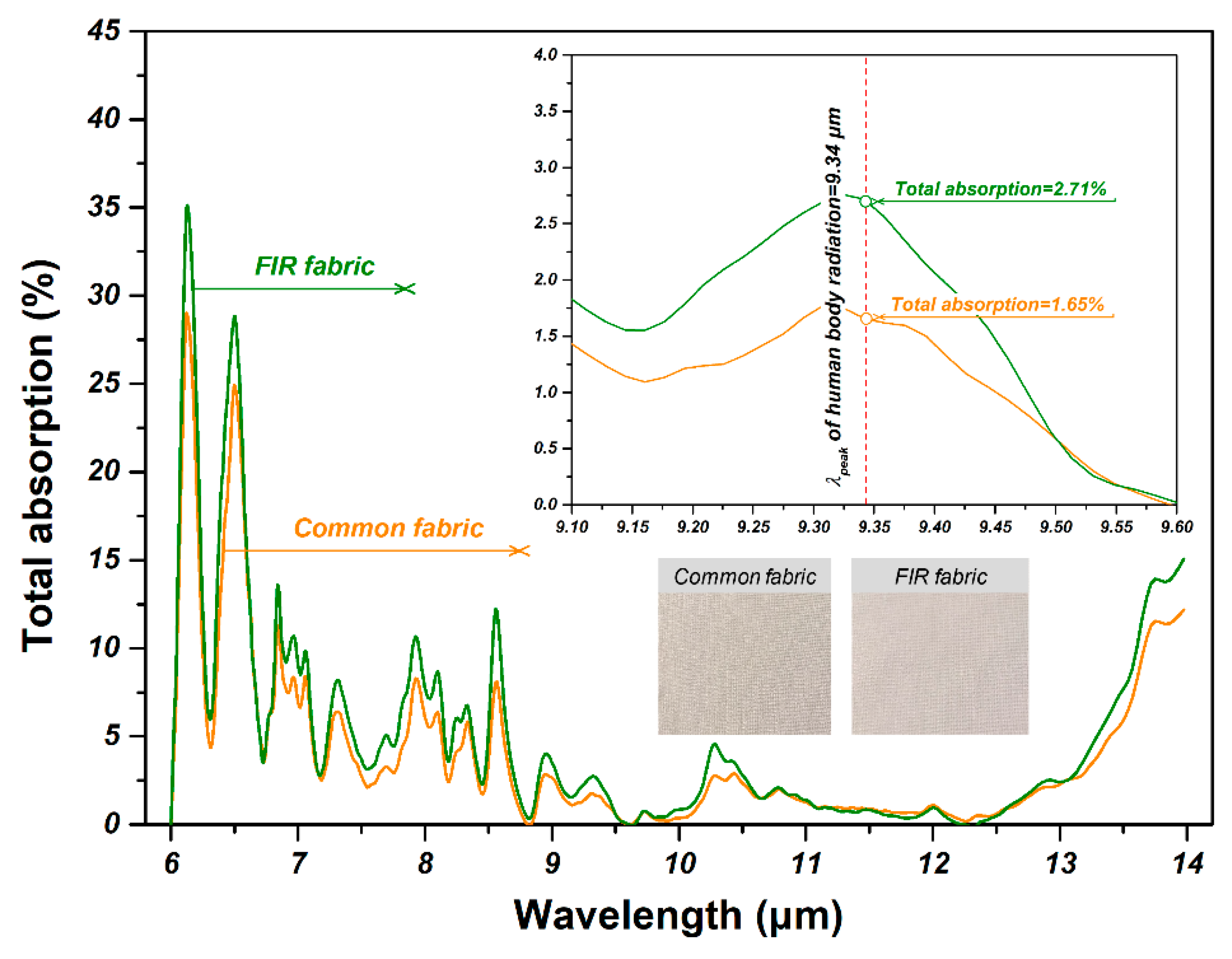
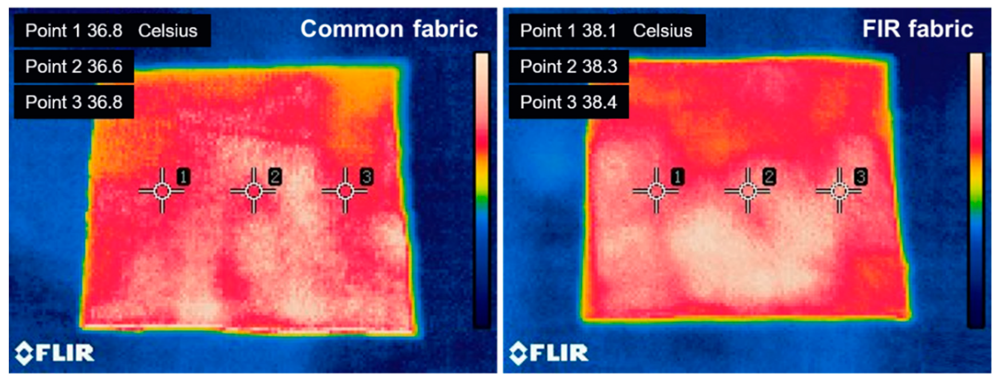
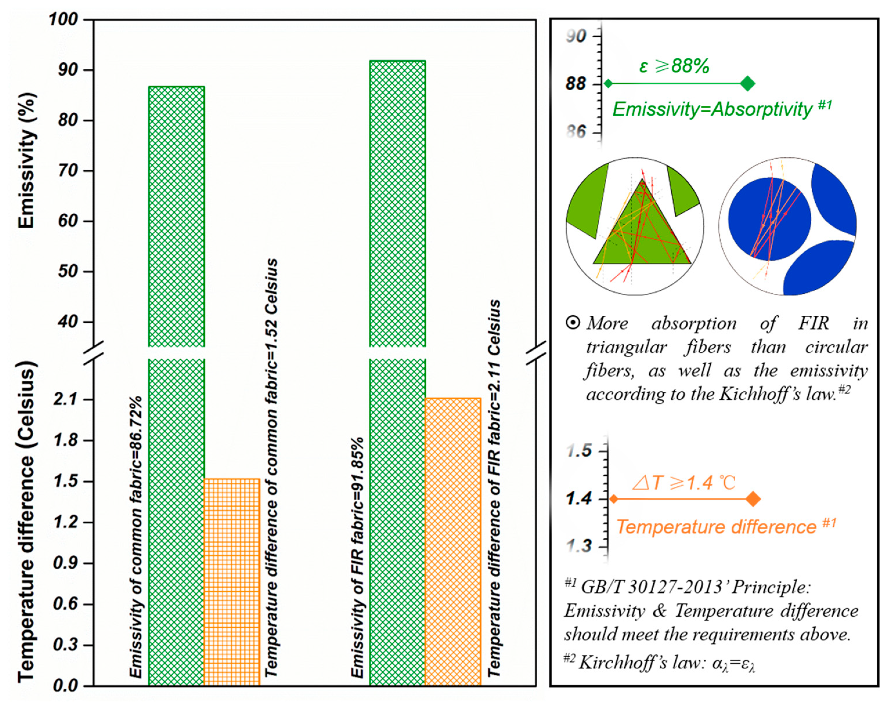
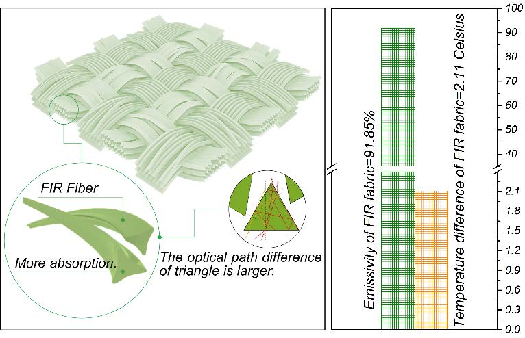
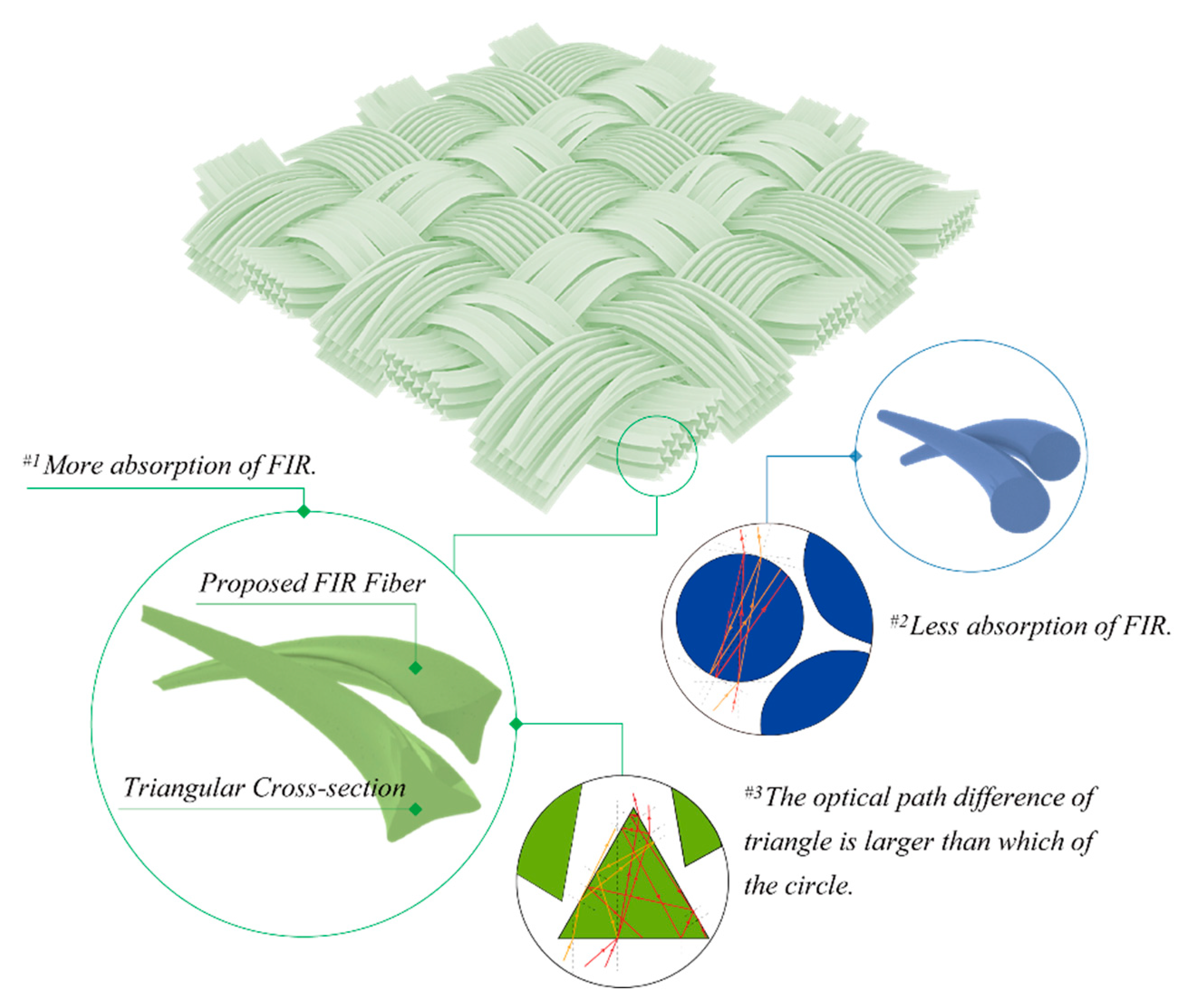
2.4. Results and Discussions
3. Theoretical Analyses and Numerical Simulations Section
3.1. Physical Principle
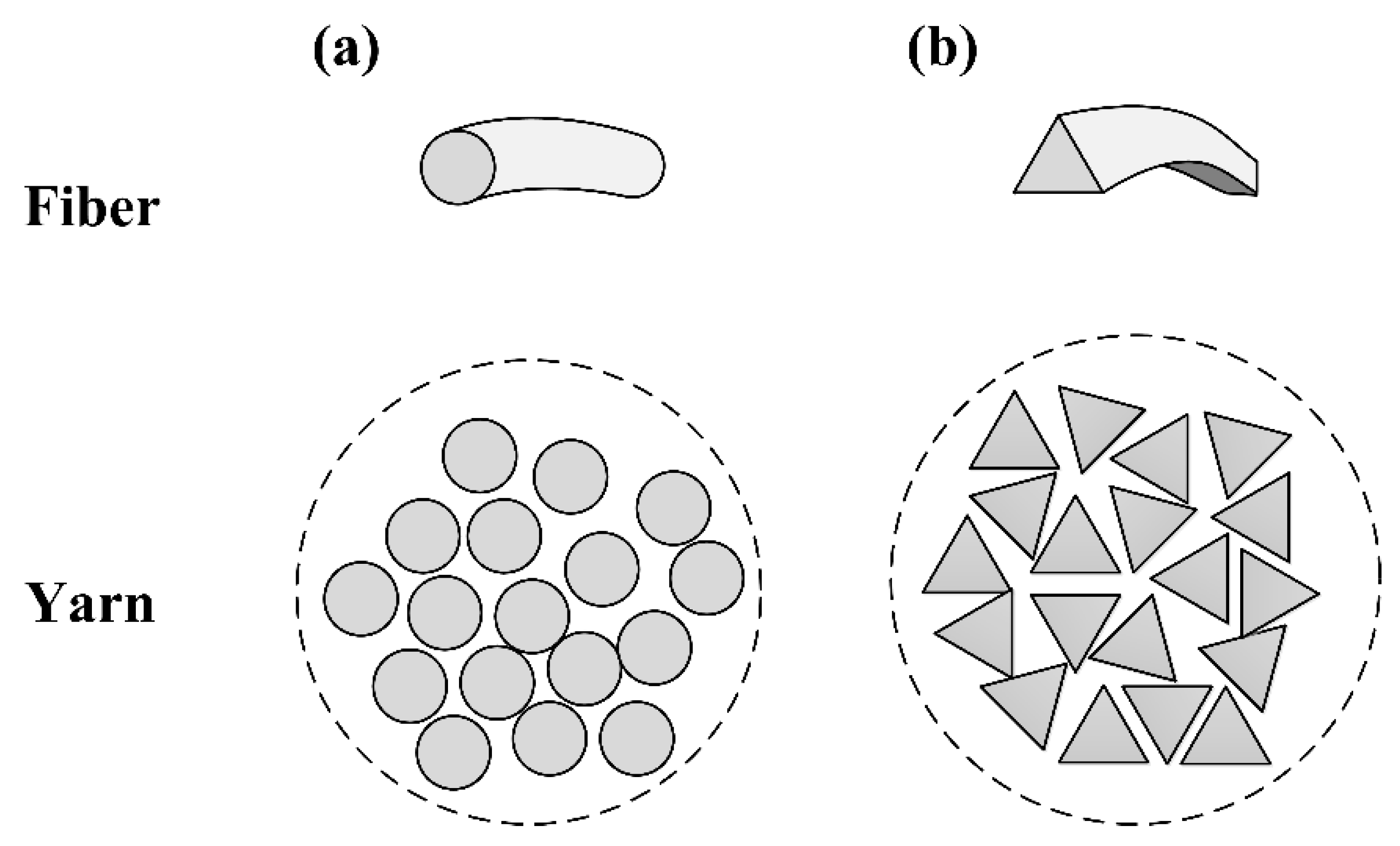
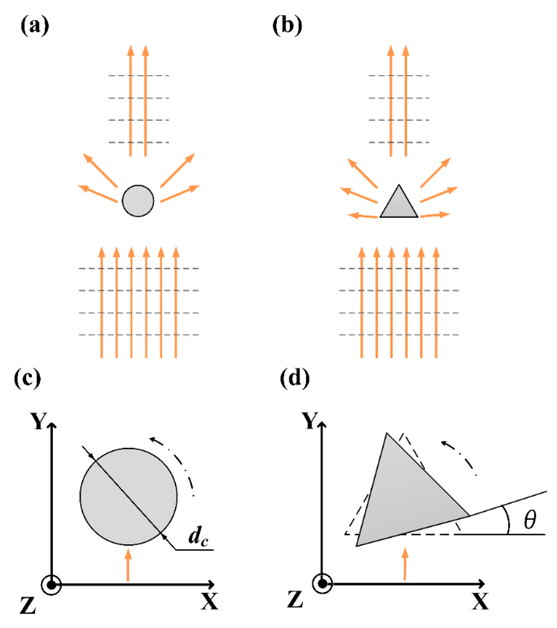
3.2. Simulation Model
3.3. Simulation Method
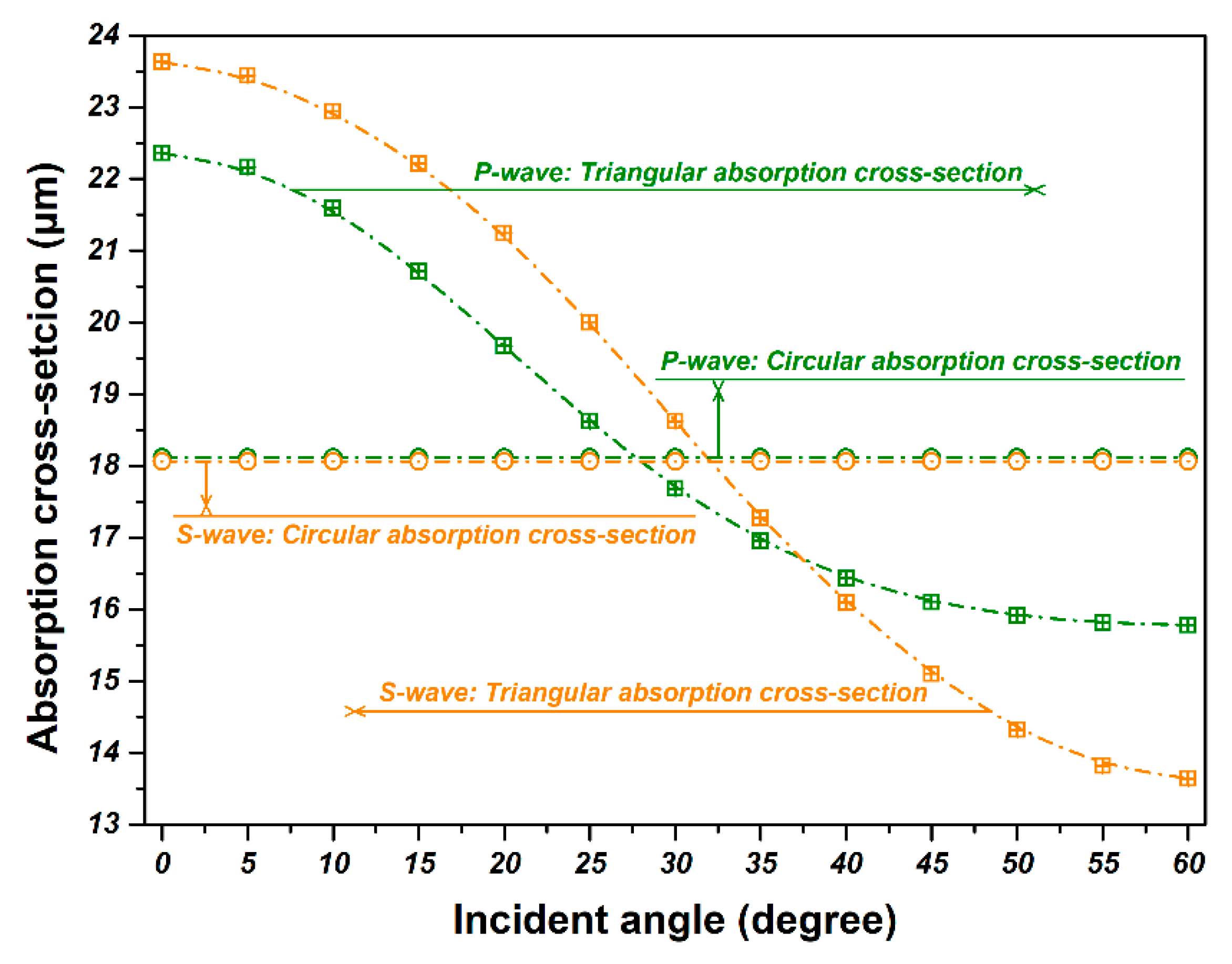
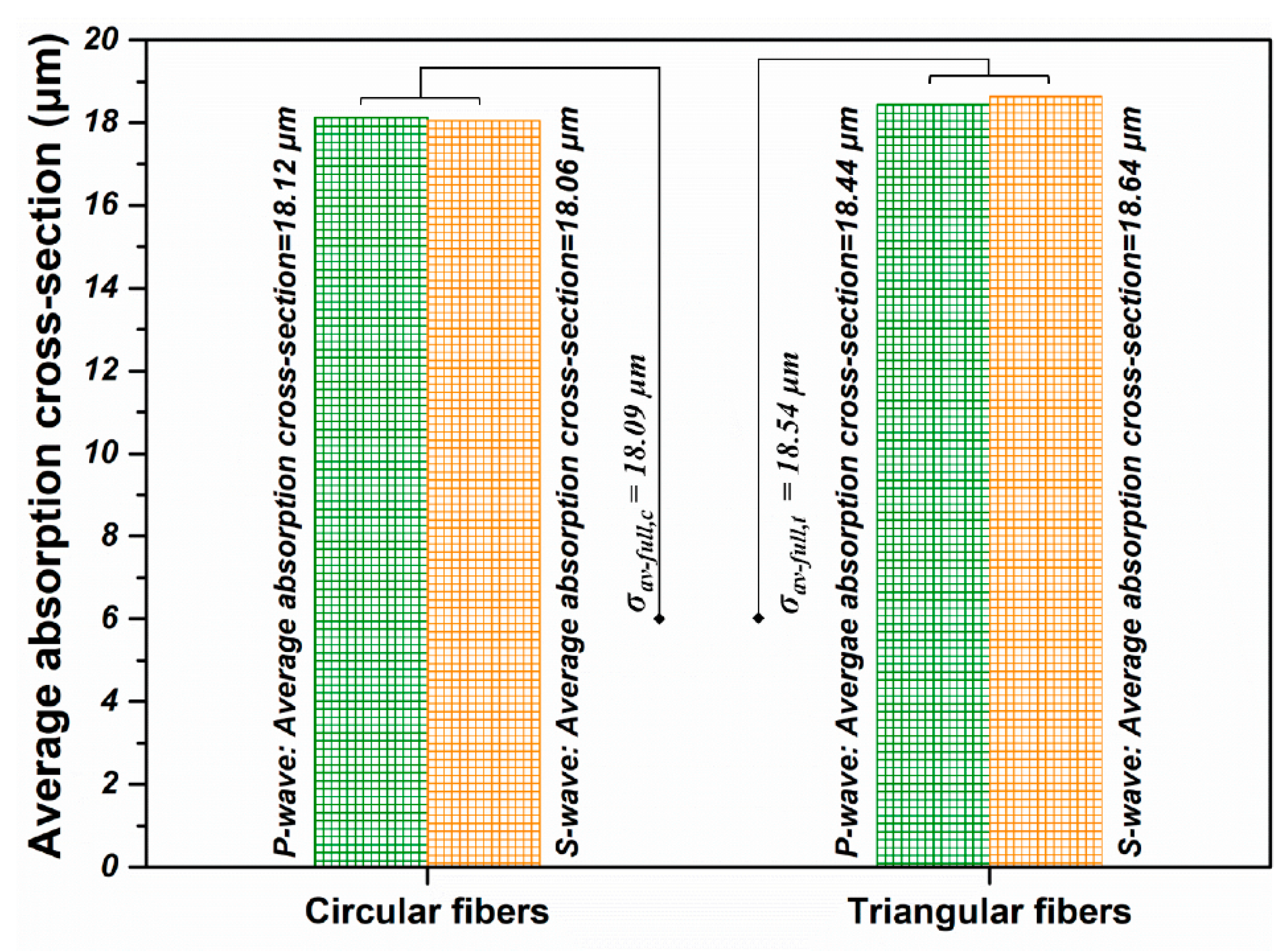
3.4. Simulation Results for a Single Fiber
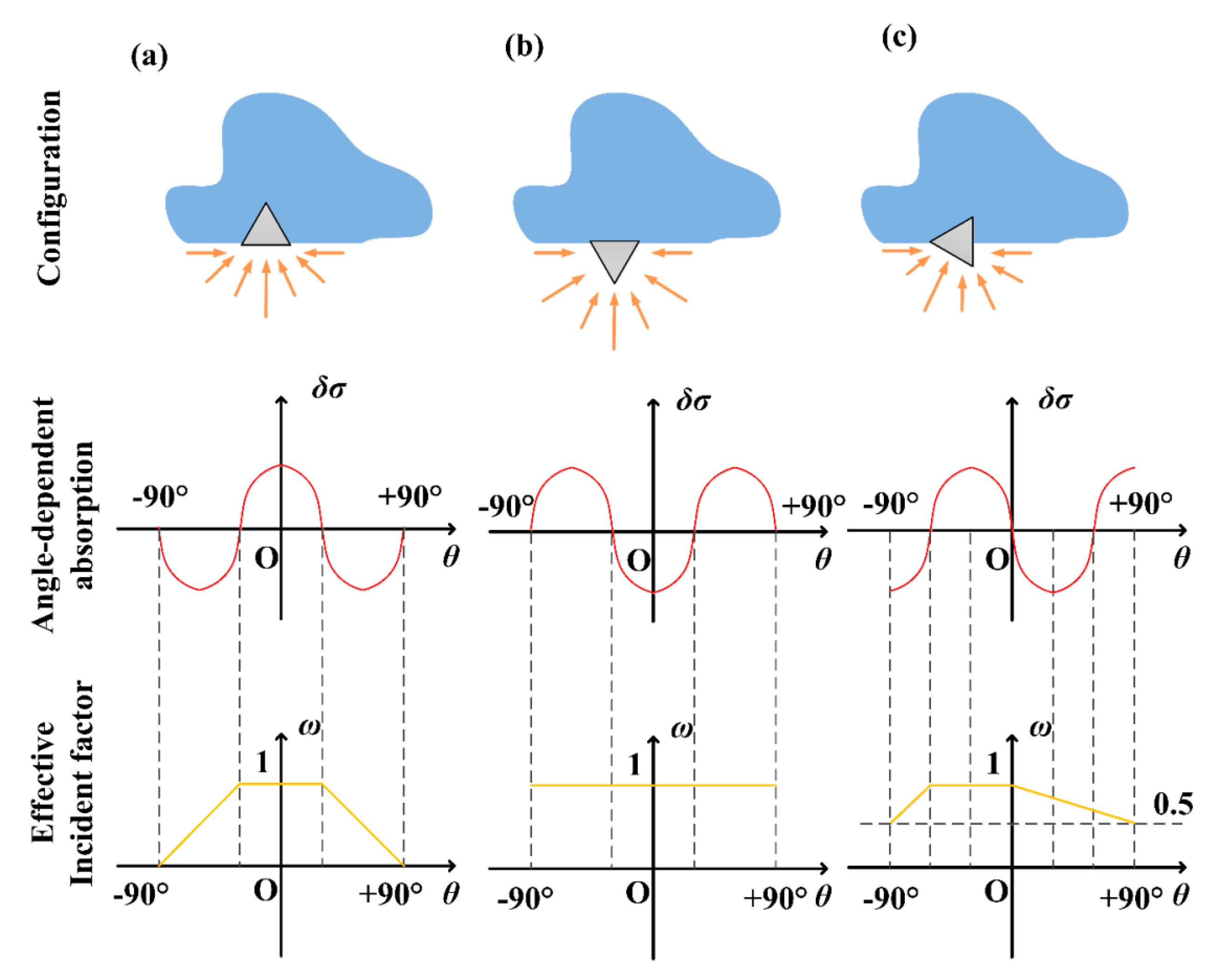
3.5. Simulation Results for Simplified Fully-Random Arrangement
3.6. Simulation Results for the Practical Tightly-Aligned Arrangement
4. Conclusions
Author Contributions
Funding
Conflicts of Interest
References
- Lin, C.A.; An, T.C.; Hsu, Y.H. Study on the far infrared ray emission property and adsorption performance of bamboo charcoal/polyvinyl alcohol fiber. Polym. Plast. Technol. Eng. 2007, 46, 1073–1078. [Google Scholar] [CrossRef]
- Li, T.T.; Pan, Y.J.; Hsieh, C.T.; Lou, C.W.; Chuang, Y.C.; Huang, Y.T.; Lin, J.H. Comfort and functional properties of far-infrared/anion-releasing warp-knitted elastic composite fabrics using bamboo charcoal, copper, and phase change materials. Appl. Sci. 2016, 6, 62. [Google Scholar] [CrossRef]
- Li, Y.; Wu, D.X.; Hu, J.Y.; Wang, S.X. Novel infrared radiation properties of cotton fabric coated with nano Zn/ZnO particles. Colloid. Surf. A 2007, 300, 140–144. [Google Scholar] [CrossRef]
- Lin, J.H.; Lin, J.Y.; Li, T.T.; Lin, Z.I.; Lin, M.C.; Lou, C.W. Performance evaluation of far-infrared composite wires applied on woven fabrics by wire-coating processing. In Proceedings of the Asia-Pacific Engineering and Technology Conference, Kuala Lumpur, Malaysia, 25–26 May 2017; DEStech Publications, Inc.: Lancaster, PA, USA, 2017. [Google Scholar]
- ChinaIRN. Available online: http://www.chinairn.com/report/20171018/154642342.html (accessed on 12 December 2017).
- Vatansever, F.; Hamblin, M.R. Far infrared radiation (FIR): its biological effects and medical applications. Photonics Laser Med. 2012, 1, 255–266. [Google Scholar] [CrossRef] [PubMed]
- Tsai, S.R.; Hamblin, M.R. Biological effects and medical applications of infrared radiation. J. Photochem. Photobiol. B Biol. 2017, 170, 197–207. [Google Scholar] [CrossRef] [PubMed] [Green Version]
- Tong, J.K.; Huang, X.; Boriskina, S.V.; Loomis, J.; Xu, Y.; Chen, G. Infrared-transparent visible-opaque fabrics for wearable personal thermal management. ACS Photonics 2015, 2, 769–778. [Google Scholar] [CrossRef]
- Hsu, P.C.; Liu, X.; Liu, C.; Xie, X.; Lee, H.R.; Welch, A.J.; Zhao, T.; Cui, Y. Personal thermal management by metallic nanowire-coated textile. Nano Lett. 2014, 15, 365–371. [Google Scholar] [CrossRef] [PubMed]
- Bahng, G.W.; Lee, J.D. Development of heat-generating polyester fiber harnessing catalytic ceramic powder combined with heat-generating super microorganisms. Text. Res. J. 2014, 84, 1220–1230. [Google Scholar] [CrossRef]
- Lin, C.C.; Liu, X.M.; Peyton, K.; Wang, H.; Yang, W.C.; Lin, S.J.; Durante, W. Far infrared therapy inhibits vascular endothelial inflammation via the induction of heme oxygenase-1. Arterioscler. Thromb. Vasc. Biol. 2008, 28, 739–745. [Google Scholar] [CrossRef] [PubMed]
- Leung, T.K.; Chen, C.H.; Lai, C.H.; Lee, C.M.; Chen, C.C.; Yang, J.C.; Chen, K.C.; Chao, J.S. Bone and joint protection ability of ceramic material with biological effects. Chin. J. Physiol. 2012, 55, 47–54. [Google Scholar] [CrossRef] [PubMed]
- Toyokawa, H.; Matsui, Y.; Uhara, J.; Tsuchiya, H.; Teshima, S.; Nakanishi, H.; Kwon, A.H.; Azuma, Y.; Nagaoka, T.; Ogawa, T.; et al. Promotive effects of far-infrared ray on full-thickness skin wound healing in rats. Exp. Biol. Med. 2003, 228, 724–729. [Google Scholar] [CrossRef]
- Chiu, H.W.; Chen, C.H.; Chang, J.N.; Chen, C.H.; Hsu, Y.H. Far-infrared promotes burn wound healing by suppressing NLRP3 inflammasome caused by enhanced autophagy. J. Mol. Med. 2016, 94, 809–819. [Google Scholar] [CrossRef] [PubMed]
- Conrado, L.A.L.; Munin, E. Reduction in body measurements after use of a garment made with synthetic fibers embedded with ceramic nanoparticles. J. Cosmet. Dermatol. 2011, 10, 30–35. [Google Scholar] [CrossRef] [PubMed]
- Conrado, L.A.L.; Munin, E. Reductions in body measurements promoted by a garment containing ceramic nanoparticles: a 4-month follow-up study. J. Cosmet. Dermatol. 2013, 12, 18–24. [Google Scholar] [CrossRef] [PubMed]
- Lai, C.H.; Leung, T.K.; Peng, C.W.; Chang, K.H.; Lai, M.J.; Lai, W.F.; Chen, S.C. Effects of far-infrared irradiation on myofascial neck pain: a randomized, double-blind, placebo-controlled pilot study. J. Altern. Complement. Med. 2014, 20, 123–129. [Google Scholar] [CrossRef] [PubMed]
- Loturco, I.; Abad, C.C.C.; Nakamura, F.Y.; Ramos, S.P.; Kobal, R.; Gil, S.; Pereira, L.; Burini, F.; Roschel, H.; Ugrinowitsch, C.; et al. Effects of far infrared rays emitting clothing on recovery after an intense plyometric exercise bout applied to elite soccer players: a randomized double-blind placebo-controlled trial. Biol. Sport 2016, 33, 277–283. [Google Scholar] [CrossRef] [PubMed]
- Kim, H.A.; Kim, S.J. Far-infrared emission characteristics and wear comfort property of ZrC-imbedded heat storage knitted fabrics for emotional garments. Autex Res. J. 2017, 17, 142–151. [Google Scholar] [CrossRef]
- Park, C.H.; Shim, M.H.; Shim, H.S. Far IR emission and thermal properties of ceramics coated fabrics by IR thermography. Key Eng. Mater. 2006, 321, 849–852. [Google Scholar] [CrossRef]
- Xiong, Y.; Huang, S.; Wang, W.; Liu, X.; Li, H. Properties and applications of high emissivity composite films based on far-infrared ceramic powder. Materials 2017, 10, 1370. [Google Scholar] [CrossRef] [PubMed]
- Pashnev, D.A.; Balagula, R.M.; Sofronov, A.N.; Firsov, D.A.; Vorobjev, L.E. Multi-particle effects in far-IR optical transmission spectra of Ge/Si quantum dots. J. Phys. Conf. Ser. 2017, 816, 012026. [Google Scholar] [CrossRef] [Green Version]
- Shin, Y.; Park, Y. Preparation and application of polymer-composited yarn and knit containing CNT/ceramic. Cloth. Text. Res. J. 2018, 36, 3–16. [Google Scholar] [CrossRef]
- Lin, Y.S.; Pan, H.C.; Lee, C.T.; Leung, T.K. Manufacturing Method for a Far-Infrared Substrate. U.S. Patent US20080217163A1, 11 September 2008. [Google Scholar]
- Hu, X.; Tian, M.; Qu, L.; Zhu, S.; Han, G. Multifunctional cotton fabrics with graphene/polyurethane coatings with far-infrared emission, electrical conductivity, and ultraviolet-blocking properties. Carbon 2015, 95, 625–633. [Google Scholar] [CrossRef]
- Hsu, P.C.; Liu, C.; Song, A.Y.; Zhang, Z.; Peng, Y.; Xie, J.; Liu, K.; Wu, C.L.; Catrysse, P.B.; Cai, L.L.; et al. A dual-mode textile for human body radiative heating and cooling. Sci. Adv. 2017, 3, e1700895. [Google Scholar] [CrossRef] [PubMed]
- Zhu, M.; Xing, Q.; He, H.; Zhang, Y.; Chen, Y.; Pötschke, P.; Adler, H.J. Preparation of PA6/nano titanium dioxide (TiO2) composites and their spinnability. Macromol. Symp. 2004, 210, 251–261. [Google Scholar] [CrossRef]
- Bohren, C.F.; Huffman, D.R. Absorption and Scattering of Light by Small Particles, 2nd ed.; Wiley-VCH Verlag GmbH & Co. KGaA: Weinheim, Germany, 2004; pp. 57–81. ISBN 9783527618156. [Google Scholar]
- Walker, J.; Halliday, D.; Resnick, R. Fundamentals of Physics, 10th ed.; John Wiley & Sons: Hoboken, NJ, USA, 2012; pp. 1190–1192. ISBN 9781118230725. [Google Scholar]
- Tompkins, H.G.; Tiwald, T.; Bungay, C.; Hooper, A.E. Use of molecular vibrations to analyze very thin films with infrared ellipsometry. J. Phys. Chem. B 2004, 108, 3777–3780. [Google Scholar] [CrossRef]


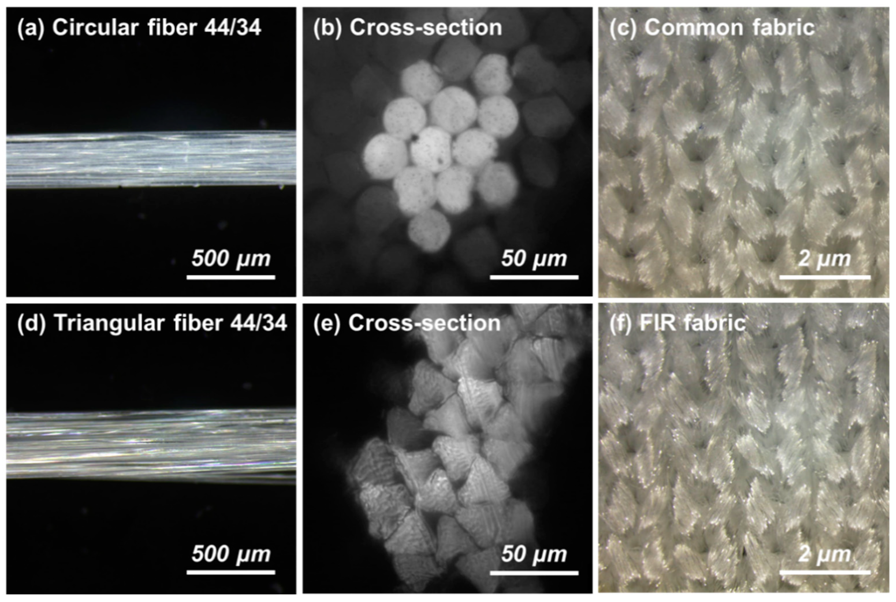
| Type of Yarns | Detail Parameters | |||
|---|---|---|---|---|
| PA fibers | Cross-section | Glossiness | Draft degree | Fineness |
| Circular and triangular | Bright | FDY | 44/34 | |
| Elastic yarns 1 | Circular, full-dull and DTY yarns with 10 filaments | |||
© 2018 by the authors. Licensee MDPI, Basel, Switzerland. This article is an open access article distributed under the terms and conditions of the Creative Commons Attribution (CC BY) license (http://creativecommons.org/licenses/by/4.0/).
Share and Cite
Tao, Y.; Li, T.; Yang, C.; Wang, N.; Yan, F.; Li, L. The Influence of Fiber Cross-Section on Fabric Far-Infrared Properties. Polymers 2018, 10, 1147. https://doi.org/10.3390/polym10101147
Tao Y, Li T, Yang C, Wang N, Yan F, Li L. The Influence of Fiber Cross-Section on Fabric Far-Infrared Properties. Polymers. 2018; 10(10):1147. https://doi.org/10.3390/polym10101147
Chicago/Turabian StyleTao, Yifei, Tenghao Li, Chenxiao Yang, Naixiang Wang, Feng Yan, and Li Li. 2018. "The Influence of Fiber Cross-Section on Fabric Far-Infrared Properties" Polymers 10, no. 10: 1147. https://doi.org/10.3390/polym10101147
APA StyleTao, Y., Li, T., Yang, C., Wang, N., Yan, F., & Li, L. (2018). The Influence of Fiber Cross-Section on Fabric Far-Infrared Properties. Polymers, 10(10), 1147. https://doi.org/10.3390/polym10101147