Article

Space Charge Characteristics and Electrical Properties of Micro-Nano ZnO/LDPE Composites

1
Key Laboratory of Engineering Dielectrics and Its Application, Ministry of Education, School of Electrical and Electronic Engineering, Harbin University of Science and Technology, Harbin 150080, China
2
Xinya Electronic co., Ltd., Wenzhou 325603, China
*
Author to whom correspondence should be addressed.
Crystals 2019, 9(9), 481; https://doi.org/10.3390/cryst9090481
Submission received: 31 July 2019 / Revised: 7 September 2019 / Accepted: 11 September 2019 / Published: 14 September 2019
(This article belongs to the Section Inorganic Crystalline Materials)

Abstract

:
The synergistic effects of zinc oxide (ZnO) Micro/Nano particles simultaneously filled in low-density polyethylene (LDPE) on the space charge characteristics and electrical properties has been investigated by melt blending micro-scale and nanoscale ZnO additive particles into LDPE matrix to prepare Micro-ZnO, Nano-ZnO, and Micro-Nano ZnO/LDPE composites. The morphological structures of composite samples are characterized by Polarizing Light Microscopy (PLM), and the space charge accumulations and insulation performances are correlated in the analyses with Pulse Electronic Acoustic (PEA), DC breakdown field strength, and conductance tests. It is indicated that both the micro and nano ZnO fillers can introduce plenty of heterogeneous nuclei into the LDPE matrix so as to impede the LDPE spherocrystal growth and regularize the crystalline grains in neatly-arranged morphology. By filling microparticles together with nanoparticles of ZnO additives, the space charge accumulations are significantly inhibited under an applied DC voltage and the minimum initial residual charges with the slowest charge decaying rate have been achieved after an electrode short connection. While the micro-nano ZnO/LDPE composites acquire the lowest conductivity, the breakdown strengths of the ZnO/LDPE nanocomposite and micro-nano composite are, respectively, 13.7% and 3.4% higher than that of the neat LDPE material.

1. Introduction

Low density polyethylene (LDPE), as a nonpolar polymeric polymer material, has been widely used in insulated cable of the power system [1,2,3] because of its high insulation resistance, low dielectric constant, and dielectric loss with minimal influence from temperature and frequency. The alternating current (AC) or direct current (DC) transmission cable must be working in a high electric field working environment for a long time. The local charge accumulation under an external electric field is caused by the carrier injection from the metal conductor into the LDPE. This is trapped in local bound states of the defects existing in the material itself, which is the space charge. The existence of space charges will cause the local electric field distributing inhomogeneously so as to induce partial discharge and, thus, initiate electrical tree growing, which eventually results in electric aging or even insulation breakdown. Therefore, the space charge characteristics play an important role in the operation and aging life of high voltage direct current (HVDC) cable [4,5]. Accordingly, utilizing the modification technologies of doping, blending, grafting, and co-polymerization to obtain the modified insulation materials used for cable with high DC breakdown field strength, a high insulation resistance coefficient, a low thermal resistance coefficient, and reduced space charge accumulation are key for improving the performance of DC power cable [6,7,8,9,10]. Domestic and foreign studies have shown that the doping of nano-filler can appreciably suppress space charge accumulations [11,12,13], increase the breakdown field strength [14,15,16,17,18], and improve insulation performance of polyethylene [19,20,21]. Cheng Xia blended nano-ZnO particles with polyethylene matrix and studied the effects of different corona aging time on space charge distribution and pressure characteristics of materials [22]. The experimental results showed that the introduction of nano-ZnO particles can improve the corona aging resistance of polyethylene to a certain extent. The volume resistivity of the composite material increases to some extent when the ZnO content is 5 wt%. In terms of the AC breakdown strength, the breakdown strength of the material increases with the increase of the filler content (<5 wt%). Furthermore, the composites doped with micro-fillers have excellent electrical corrosion resistance and thermal properties [23]. The thermal conductivity and breakdown field strength of epoxy resin containing micrometer alumina were studied by Wang Qi [24]. The results showed that the thermal conductivity of the epoxy resin matrix was improved by micron alumina, and the conductivity of epoxy resin matrix was 1.63 times higher when the mass fraction of micron alumina was 20%. However, until now, the further study of whether the co-doping of nano-fillers and micro-fillers in polymer matrix materials will improve space charge distribution and DC breakdown strength due to a synergistic effect has not been reported in literature.
Micro/nano-scale zinc oxides (ZnO) are characteristic multifunctional materials with high chemical stability and good biological compatibility, which has unique catalytic, electrical, optical, mechanical, and antibacterial properties that could have been employed in various applications. It can effectively utilize the individually-specific properties of the micro-scale and nano-scale ZnO to develop novel functional composites, and realize the prospective applications by the complementary or enhanced advantages of them [25,26]. In the present paper, the nano ZnO/LDPE, micron ZnO/LDPE, and micro nano ZnO/LDPE composites are prepared by the nano-filling technique. The space charge distribution, DC breakdown field strength, and conductivity are tested to explore the modification mechanism of space charge and electrical properties attributed to filling nano and micro ZnO particles into polyethylene material.

2. Methods and Materials

2.1. Composites Preparation

The LDPE matrix used in the preparation is a standard Q/SH3045004 model with melting index of 1.5 g/10 min (Sinopec Petrochemical Co., Ltd., Shanghai, China) and the micro-scale and nano-scale zinc oxides in 99.99% purity with particle sizes of ~1 μm and ~30 nm, respectively, (micro-ZnO and nano-ZnO, Decodo Gold Technology Co., Ltd., Beijing, China) are employed as filling additives, which are initially surface modified with silane coupling agent KH 570. As the particle size of nanofiller accounts for the correlated modification mechanism and, accordingly, determines the acquired electric properties of prepared nanocomposites, the pristine nanoparticles have been characterized by scanning electronic microscopy (SEM), which is shown in Figure 1. It is confirmed that the ZnO microparticles and nanoparticles utilized in composites preparation are majorly distributed in the sizes of 1–2 μm and 25–40 nm, which substantially meet the requirements of our experimental proposition.
The nano-ZnO/LDPE, micro-ZnO/LDPE, and micro-nano ZnO/LDPE composites are fabricated by the two-step melt blending method using XLB25-D flat plate vulcanizer with a step-type boost. The temperature is 140 °C and the pressure is individually set as 0, 5, 10, and 15 MPa for the pressing time of 20 min to obtain three kinds of specimens with different thicknesses. The samples of 300, 200, and 100-μm thicknesses are, respectively, chosen for space charge, breakdown strength, and electrical conductance tests. The electrodes are evaporated on both sides of the sample adopted by the vacuum coating machine (diameter of measuring electrode is 50 mm, outer diameter of protective electrode is 54~74 mm, and the diameter of a high voltage electrode is 74 mm). The samples are pre-treated in a short-circuit at 60 °C under a vacuum environment for 24 h before testing. The samples are numbered according to constitutes of composites, as listed in Table 1.

2.2. Polarizing Microscopy (PLM) Characterization

In order to characterize the effects of micro-ZnO and nano-ZnO fillers on the crystallization process of LDPE, the composite morphology is observed via a Leica DM2500P polarizing microscope. Before observation, the samples are placed in 5% potassium permanganate/concentrated sulfuric acid solution to be corroded for 24 h. Then the samples are removed from solution and cleaned in an ultrasonic machine. The crystalline morphology of the composites is observed on the glass slide in clear brightness.

2.3. Space Charge Test

The space charge distributions of composite materials are measured by the Pulse Electronic Acoustic (PEA) method, as schematically shown in Figure 2 [27,28], with a DC power source of 0–40 kV and pulse width of 30 ns. The samples are applied by the DC electric field of 10, 20, and 40 kV/mm, respectively, for 30 min and then short connected for 30 min, to investigate the space charge distribution in composite materials under a different field strength and analyze quantitatively the attenuation of space charge after a short circuit.

2.4. Breakdown Strength and Conductance Test

The DC breakdown test is carried out on the composite materials with the applied voltage being raised at a constant speed of 1 kV/s until the materials are broken-down. The DC breakdown test uses a two-electrode system with the electrode diameters of 25 mm and 50 mm for the upper and lower electrodes, respectively. In order to prevent the tested sample from discharging along the surface in the testing process, the sample together with the whole electrode system are immersed in the cable oil.
The electric breakdown strength (field) is generally analyzed by Weibull statistics of 2-parameter fitting measured data [29]. The breakdown data are statistically fitted by the 2-parameter Weibull distribution as follows.
P ( E ) = 1 exp [ ( E / E b ) β ]
where P(E) denotes failure probability of cumulative sampling, E is the experimental breakdown electric field, β represents the shape factor, and Eb identifies the breakdown electric field for P = 63.2%, which shows Weibull statistical breakdown strength. The P for definite E is calculated by the following equation.
P = i 0.5 n + 0.25
where i symbolizes a failure ordinal number and n indicates the total number of the test. The steady-state electrical current is measured by a current detector with 10–14 A measurement accuracy. By sampling each test point for 600 s in time, the conductance current of insulating material is measured with the electric field increasing in a step boost mode at ambient temperature.

3. Results and Discussion
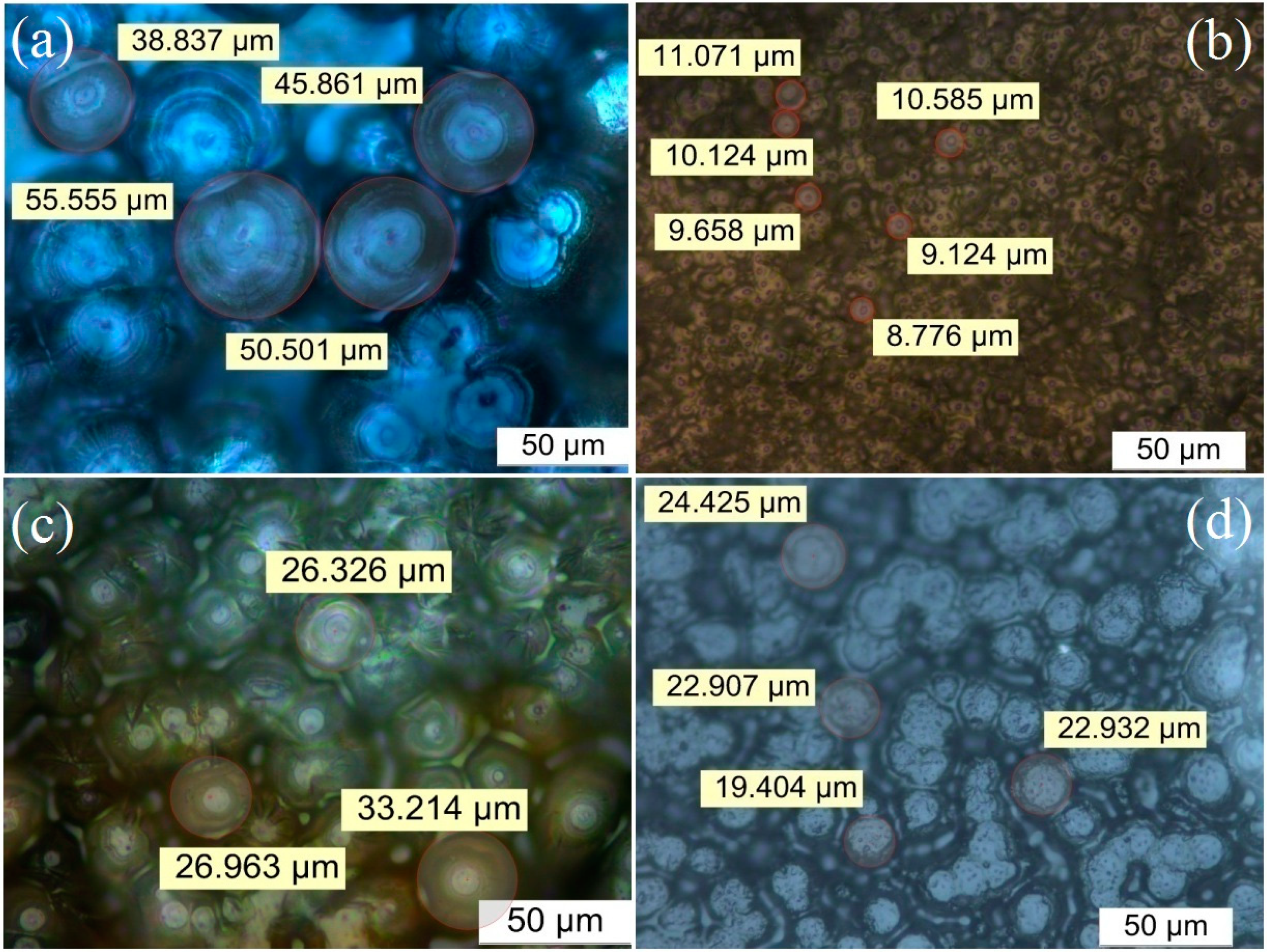
3.1. PLM Morphology

The PLM images of neat LDPE and three kinds of ZnO/LDPE composites are illustrated in Figure 3. It is indicated that the micrometer scale crystalline grains in a uniform arrangement dominate the morphological structure in neat LDPE, between which the substantial amorphous regions also exist and the average diameter of the spherulites is 47.7 m. Both the micro and nano-ZnO fillers remarkably decrease the crystalline grain size of the LDPE matrix, and smaller ZnO filler renders a smaller size of crystalline grains in LDPE. The average diameters of micro- ZnO/LDPE, micro-nano ZnO/LDPE and nano-ZnO/LDPE composites are 28.8 μm, 21.5 μm, and 9.5 μm, respectively. The morphological variation can be reasonably comprehended and pictured by the heterogenous nucleation theory of Binsbergen, which proposes that the nucleating agent acts as a heterogeneous nucleation during the crystallization of the polymer. The non-polar part of the nucleating agent forms a dent on the surface, accommodates the molecular chains of the polymer, and arranges them in order to promote nucleation. As shown in Figure 4, the schematic images of partial and complete crystallization for micro and nano ZnO/LDPE composites as well as the filled ZnO particles contribute to the heterogeneous nucleation of LDPE crystallization, which results in more densified crystalline morphology.

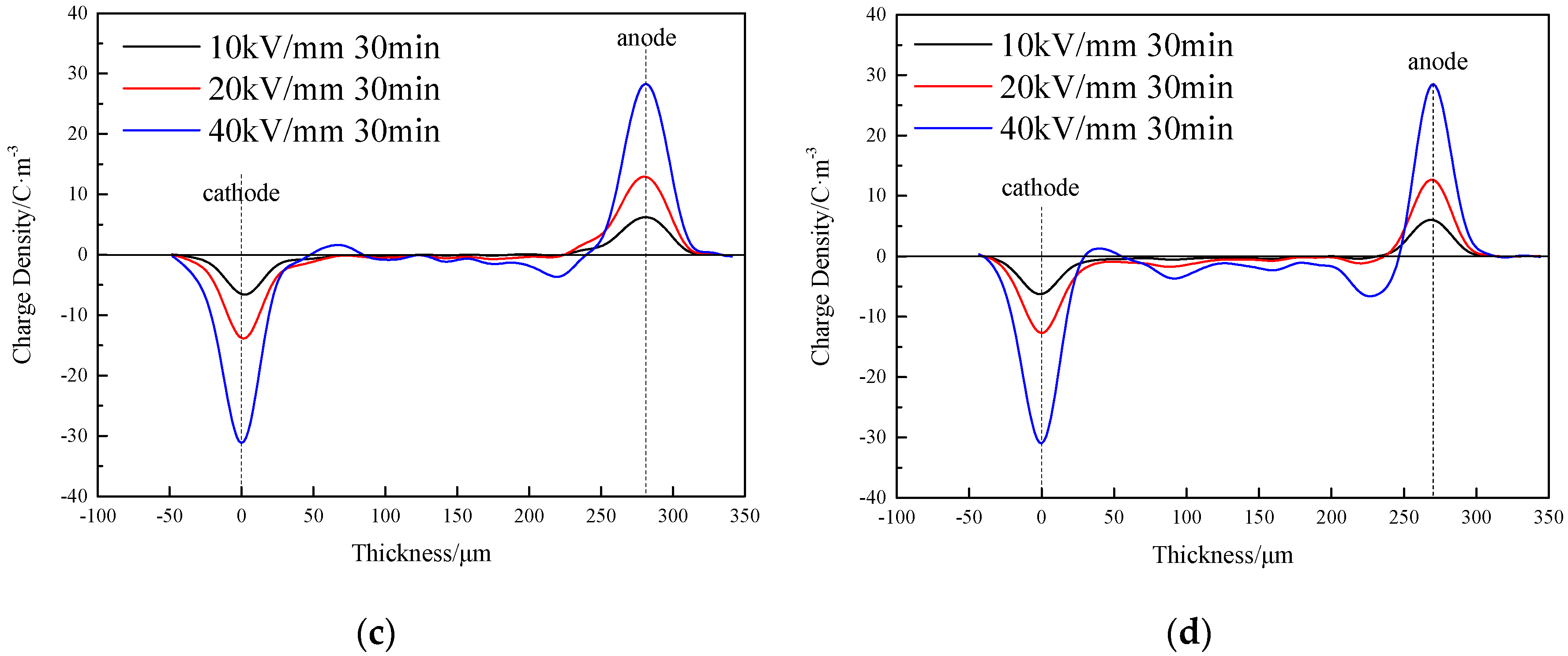
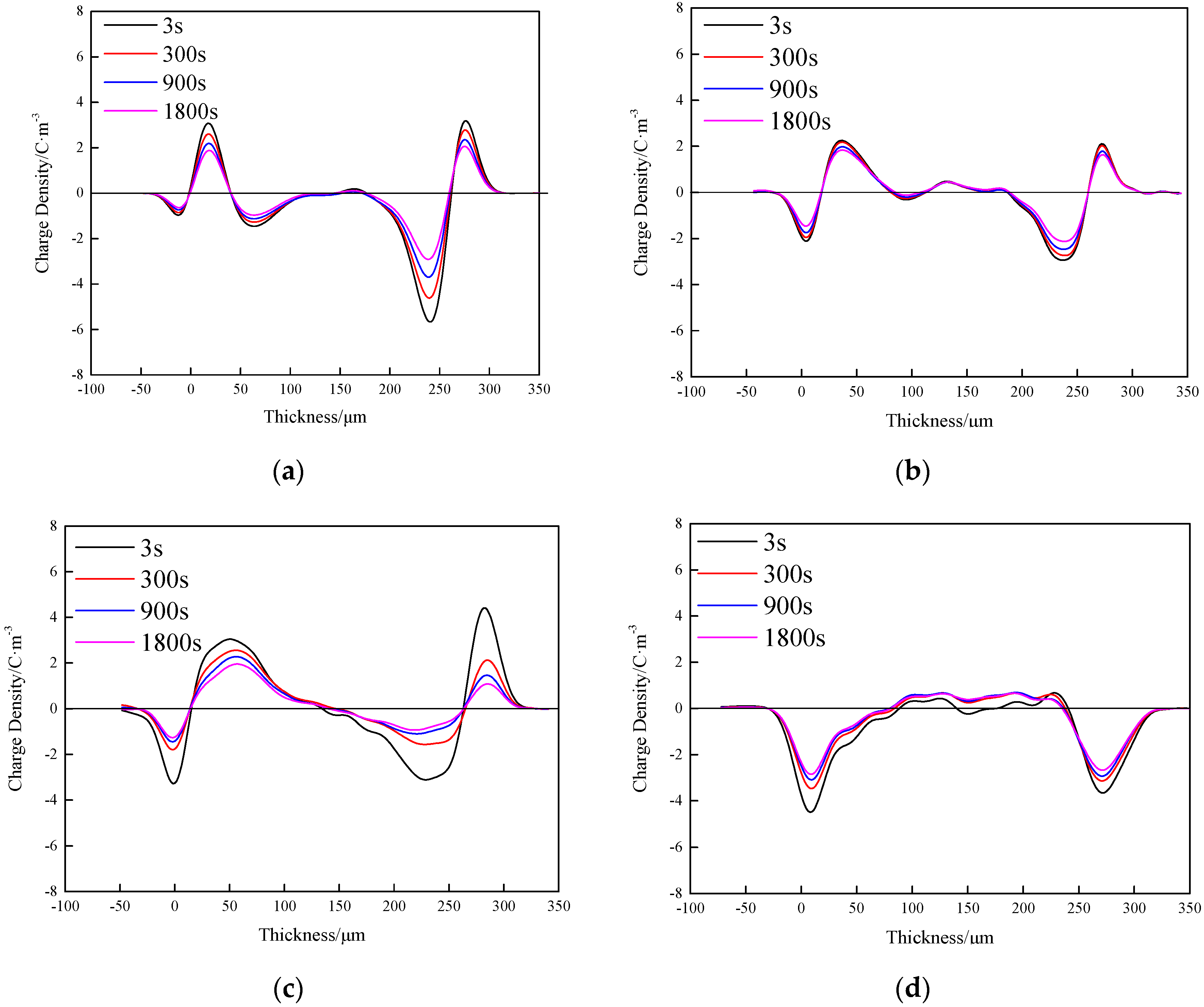
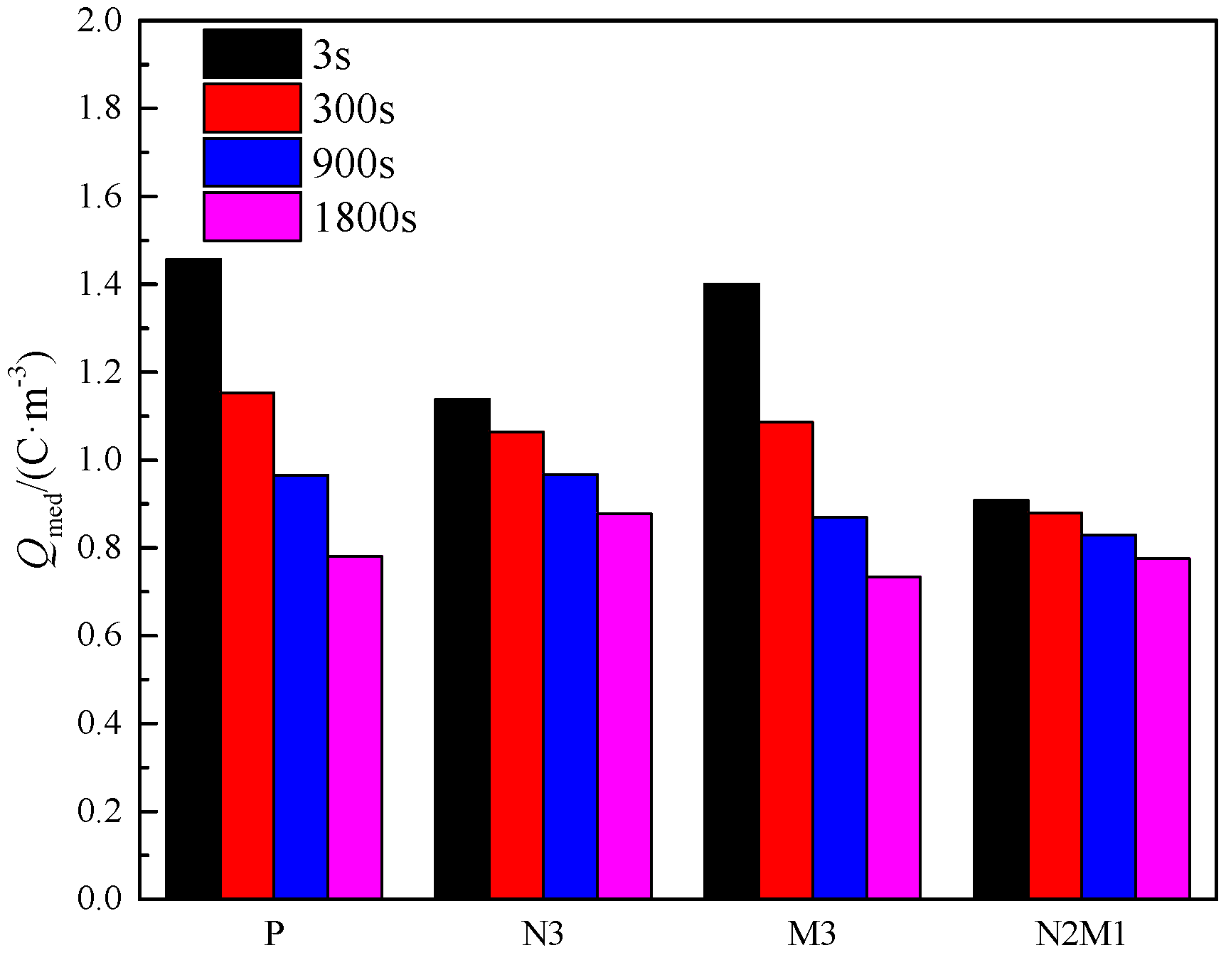
3.2. Space Charge Characteristics

The space charge distributions of neat LDPE and ZnO/LDPE composites are measured after applying a DC electric field for 30 min, which the results show in Figure 5. No appreciable space charge accumulation appears under a 10 kV/mm electric field for all the tested materials. When the applied DC electric field increases to 20 kV/mm, substantial positive space charges accumulate near the anode in neat LDPE and a spot of homo-charges with the maximum charge density of 1.4 C·m−3 arises at the location of 100 μm near the cathode in the nano-ZnO/LDPE composite. However, for the micro-ZnO/LDPE and micro-nano ZnO/LDPE composites, a 20 kV/mm electric field has not yet injected considerable space charges. When the applied electric field increases from 20 kV/mm to 40 kV/mm, the positive space charges abate and a negative space charge appears near the anode while the hetero charge accumulation near the cathode increases for neat LDPE. For all the three ZnO/LDPE composites, the space charge distribution represents similar characteristics since hetero charges evidently accumulate near both electrodes with an identical positive charge density of 1.0 C·m−3 near the cathode and the highest negative charge density of 6.6 C·m−3 near the anode in a nano-ZnO/LDPE composite. Furthermore, notable negative space charges accumulate at the locations of 100 μm and 150 μm near the cathode with maximum charge densities of 2.3 C·m−3 and 3.3 C·m−3, respectively, in the nano-ZnO/LDPE composite, while no space charge accumulation has been observed inside the micro-ZnO/LDPE and micro-nano ZnO/LDPE composites except for hetero charges accumulating near the electrodes.
Figure 6 exhibits the space charge distributions for all the investigated materials measured at the times of 3 s, 300 s, and 900 s after an electrode short connection for a 40-kV/mm applied electric field. In combination with the averaged charge density calculated from the short connection process shown in Figure 7, the averaged charge densities of LDPE, M3, N3, and N2M1 materials all attenuate gradually from the initial values of 1.5 C·m−3, 1.4 C·m−3, 1.1 C·m−3, and 0.9 C·m−3, respectively, to nearly the same residual value of 0.8 C·m−3 when the short connection persists from 3 s to 1800 s.
The sources of space charge in the polymer are primarily derived from electrode injection, impurity decomposition, and internal polarization. The positive charge density of neat LDPE at the anode increases first and then decreases as the applied field increases. When the electric field is not too high, the electric conductivity of neat LDPE is relatively small, and, except for the defects of a molecular chain segment, there is almost no interfacial phase inside LDPE. Hence, the charge injection from electrodes increases and the positive charge begins to accumulate near the anode when the electric field increases in a low field region. When the electric field rises to a critical value that the space charge injection and carrier transport reaches equilibrium near the anode, the charge density approaches the highest value. As the electric field continues to increase, the conductivity of neat LDPE increases greatly due to the saturation of occupied trap states (space charges) and the negative charges accumulate near the anode. The nanoscale and microscale ZnO fillers contribute effectively to heterogeneous nuclei so as to improve the crystallinity of LDPE and, remarkably, reduce free volume inside LDPE, which results in a decreased charge carrier mobility. In addition, a great deal of ZnO/LDPE interfaces generated by filling ZnO nano-particles and micro-particles will change the primary polarization mode and introduce massive traps, which act as charge capture centers to induce a hetero charge near filler/matrix interfaces.
The space charge accumulation in the N2M1 composite is not clear due to the hetero charges being induced by interfacial polarization cancel out the homo charges injected from electrodes. The neat LDPE with a relative larger spherocrystal presents only low density and shallow depth of traps by intrinsic defects of molecular chain segments, which causes relatively high carrier mobility, so that the hetero charges near the electrodes cannot be rapidly neutralized with more residual under a short connection due to the lack of homo charge injection. However, the internal polarization modes of the composites are explicitly discriminated from that of the neat LDPE, and the polarization modes are primarily derived from interface polarization by trapping. Therefore, when the applied field is removed, the polarization process disappears immediately, which represents that the trapped hetero charge generated near the filler/matrix interfaces are neutralized promptly. The space charges generated by a trap capture have been neutralized in a short connection for 3 s in the composites, which indicates that the initial charge residue and decay rate are lower than that of the neat LDPE.
At the end of the short-connection process, the residual charge densities of the four materials are essentially equal, except for the slightly higher value for N3 composite due to the fact that not all the traps have captured charges. As a result, the superfluous local charges cannot be neutralized and remain in samples. Moreover, the ZnO/LDPE interfaces in the N3 composite possess the largest internal volume fraction and, thus, provide the highest trap density. Therefore, the N3 sample shows the largest charge residue, while the M3 composite with the lowest trap level and density represents the smallest charge residue.

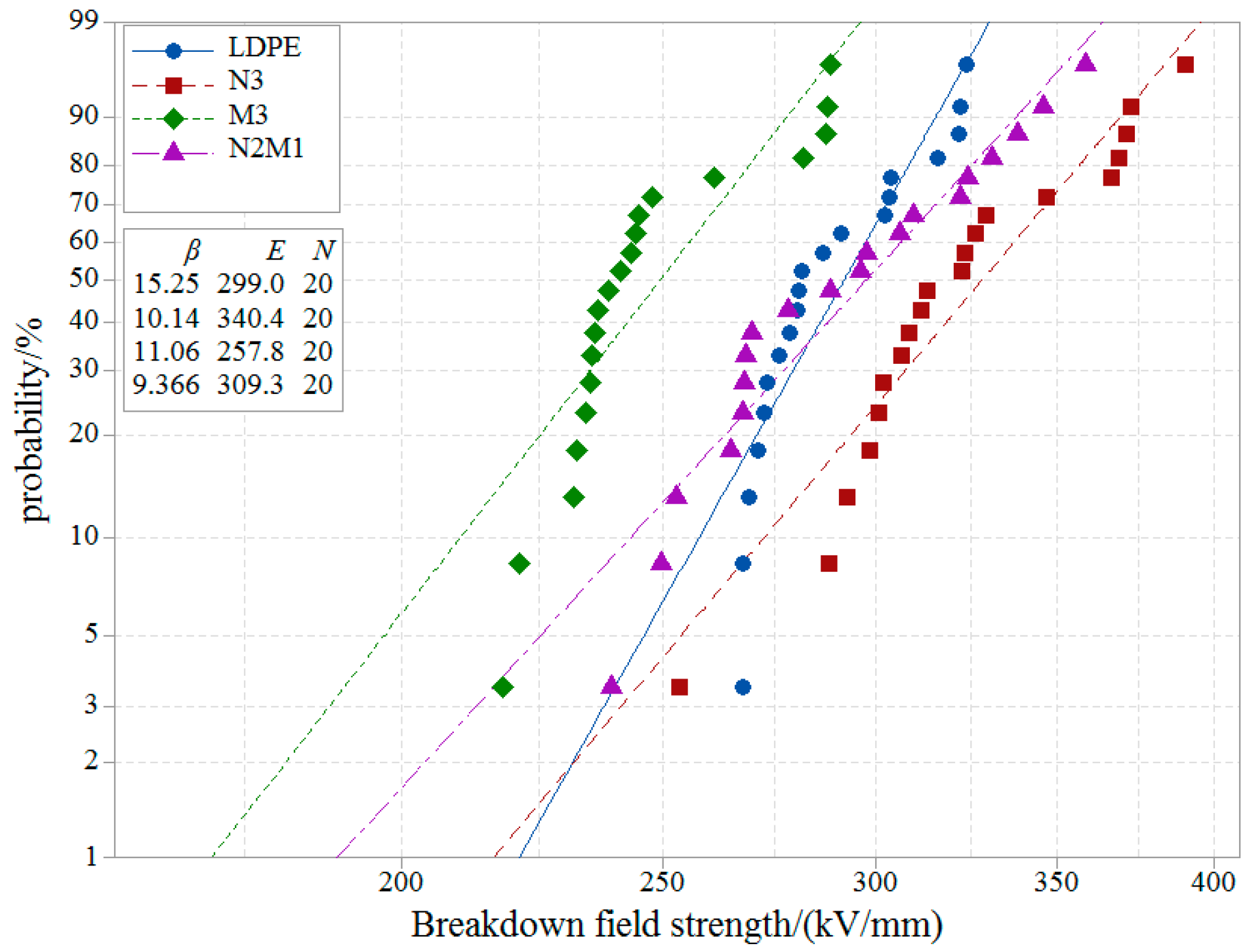
3.3. DC Breakdown Strength

The DC breakdown strength (DBS) test results for LDPE and all the synthesized ZnO/LDPE are analyzed by Weibull statistics as 2-parameter Weibull fitting in Figure 8. The 63.2% probability cumulative DBS together with fitting parameters of Weibull distribution for all the samples are listed in Table 2. Characteristic DBS enhancement can be evaluated by the field strength at 63.2% breakdown probability calculated from scale and location parameters of the fitted Weibull distribution. The nano and micro-nano ZnO/LDPE composites exhibit remarkable DBS improvement of 13.7% and 3.4%, respectively, when compared with neat LDPE, which demonstrates the effect of deep-traps introduced at massive filler/matrix interfaces by filling ZnO particles. This can capture charge carriers and inhibit space charge accumulation under a DC electric field. Furthermore, although the micro ZnO/LDPE sample exhibits lower characteristic DBS, the Weibull shape factor is notably decreased in comparison with neat LDPE. In contrast, the filling of micron ZnO with a specific surface area can only engender relatively lower density of shallow level traps with the poor ability of trapping charge. Besides, the micron ZnO filled into the matrix is as an impurity during the DC breakdown process, so that the breakdown field strength is reduced when compared with neat LDPE, as shown in Figure 8 and Table 2.
The dielectric modification effect of filling ZnO nano-particles and micro-particles is still retained for the low breakdown probabilities, as shown in Figure 7. It is reasonable to correlate DBS improvement with the increasing superficial area of ZnO fillers. This result supports the electron trapping model of the interface polar group and verifies that the ZnO additive is a promising candidate to improve dielectric properties of polymer materials. Further evidence is shown that the candidate inorganic particles have been filled with higher polarity interfaces, which is a composite to polymers so as to further increase DBS [28,29,30].

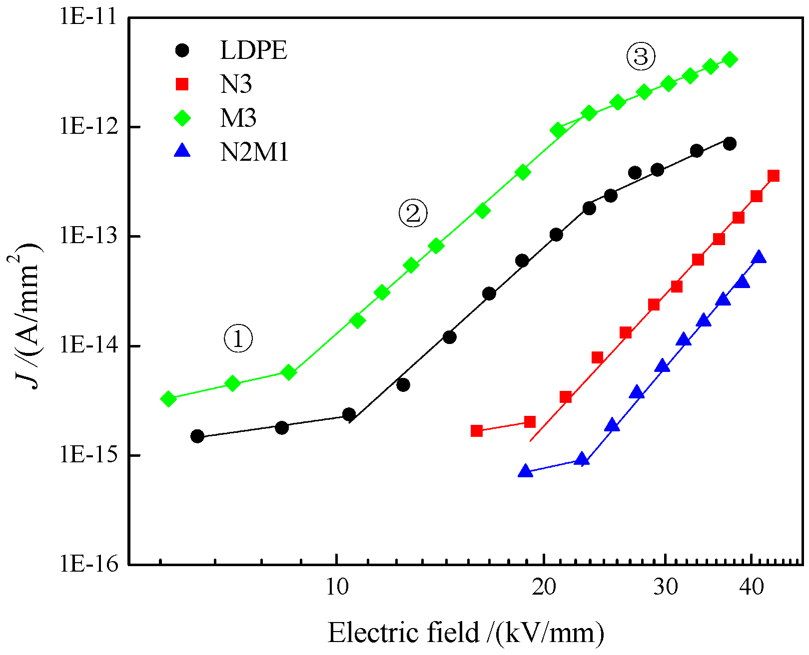
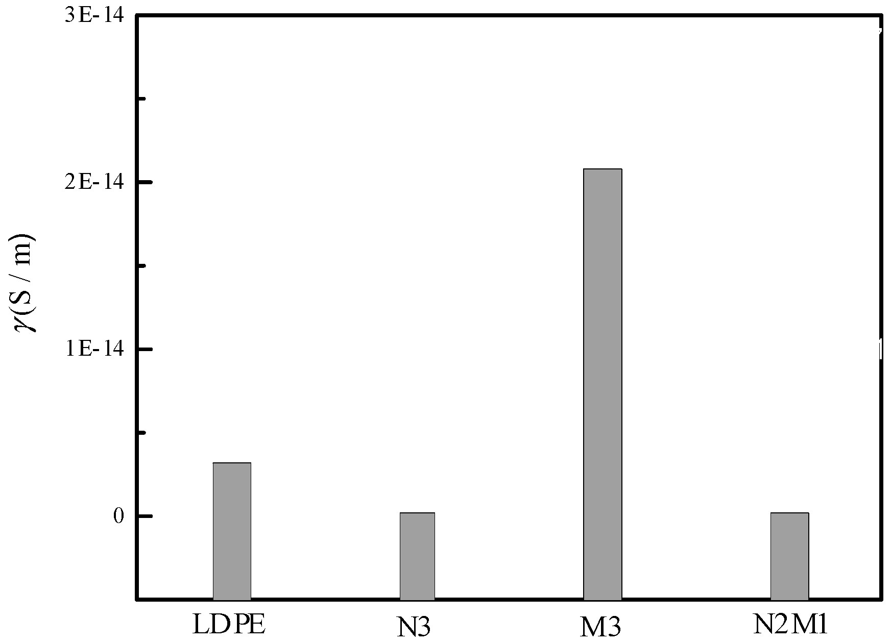
3.4. Electrical Conductance

Neat LDPE and micro-nano ZnO/LDPE composite represent three characteristic varying features in conduction-electric field curves, as shown in Figure 9, which are consistent with the recent reported results and, thus, verify the accuracy of our conductance tests [31]. Conduction currents exhibit a considerable reduction for ZnO/LDPE composites, which can be reasonably depicted by a space charge limited current (SCLC) theory. Base on SCLC theory, three conductance regions attributed to different conduction mechanisms will appear in complete J-E curves for ideal solid dielectrics.
In the first conductance region of low electric field (indicated by ① in Figure 9), the charges injected from electrodes into dielectric materials will be captured by the traps introduced from the intrinsic structural defects of polymer materials, and, hence, cannot contribute to conduction current. Thus, the exponential factor of current density varying with electric field (the gradient of J-E curves in logarithmic coordinates) is approaching 1.0, which means that the conduction current is determined by Ohm’s law, identical to the results listed in Table 3 for four kinds of investigated materials. In the second conductance region (indicated by ②), where the electric field exceeds the threshold field E1, the injected charges outnumber the traps and the density of free charge carriers will increase with the increasing electric field. Accordingly, the conduction current increases with the electric field in an exponential factor higher than 2.0, which cannot be described by Ohm’s law. The gradient of J-E curves in logarithmic coordinates approaches 5.5, shown in Figure 8, which verifies that the conduction current in this region is determined by the trapping-limited space charge mechanism [32]. The threshold field E1 is correlated to the trap level depth in the following equation [33].
E 1 exp ( Δ U k T )
where k is the Boltzmann constant, T is the absolute temperature, and ΔU represents the trap level depth. Because the trapping depth of ΔU has a great influence on the threshold field E1, the internal trapping depths of four composite materials can be deduced, according to the threshold field, which, in order, are ΔU(N2M1) > ΔU(N3) > ΔU(LDPE) > ΔU(M3). In the third region, with the further increase of the electric field, the amount of charge injected into the dielectric materials approaches saturation so that the density of free charge carriers retains a constant value. Therefore, the current density varying with the electric field is similar to region ① as conducting without traps. It has been reported that E2 is proportional to the trap density internal to the dielectric materials [34]. It is noted from Table 3 that the E2 of N2M1 and N3 is beyond the range of the measured range, which indicates that the trap density of the N2M1 and N3 composites are apparently higher than that of neat LDPE. In comparison, the values of E2 for LDPE and M3 show a minimal difference, which demonstrates that ZnO micro-filler has not contributed to trap density of the LDPE matrix. The conductivity of the composites is compared in order as N2M1 < N3 < LDPE < M3 in the range of measured voltage.
Figure 10 shows the electrical conductivity of neat LDPE and ZnO/LDPE composites under the same DC electric field. The DC conductivity results of all samples are concluded in the order M3 > LDPE > N3 > N2M1 in the testing range of the electric field. The charge carriers transport with relatively higher mobility in larger free volume due to the bigger spherulites of neat LDPE, so that it is easier to form conductive channels inside the neat LDPE. The filling of inorganic particles plays the role of a heterogeneous crystal nucleus. During the crystallization of LDPE, the size of crystal grain decreases and its arrangement becomes denser, and the physical crosslinking between the molecular segments of polyethylene leads to the reduction of the free volume in the composite samples, which will hinder the carrier transport. More importantly, filling micro-fillers and nano-fillers generates a large number of charge traps at filler/matrix interfaces. When the charges are injected from the electrode, a part of them is captured by high density traps to form a space charge layer near the electrode, which is, as an electrostatic shielding layer to exclude the charge being further injected from the electrode, consequently, it decreases the number of free charge carriers and improves the breakdown strength of composites. At the same time, the introduced traps of high density will efficiently scatter with injected charges especially after trapping carriers to draw in coulomb repulsion, which reduces the carrier mobility in the electric field direction. Therefore, the conductivity of N2M1 and N3 composites is relatively lower. In contrast, interface area induced from filling micron ZnO is relatively small and the traps introduced at interfaces are mostly in shallow energy levels, so that the ability of trapping charge is relatively poor and the trap density is not high. This results in the highest conductivity, as shown in Figure 10.

5. Conclusions

The space charge characteristics, DC breakdown, and conductivity properties of micro-nano ZnO/LDPE composites and the correlated synergistic effects of ZnO Micro/Nano fillers are investigated by associating the analyzed results of PLM microscopy, PEA, and charge carrier transport tests. The space charge accumulation can be suppressed by filling micro-particles and nano-particles into the LDPE matrix, and the micro-nano co-filled ZnO/LDPE composites approach the most improved space charge distributions due to the synergistic effect. The DC breakdown strengths are significantly enhanced by 13.7% and 3.4%, respectively, for the nano ZnO-filled and micro-nano co-filled composites in comparison with neat LDPE. Whereas the micro-scale ZnO fillers represent inappreciable modification of insulation strength for LDPE. It is reasonably demonstrated that the micro-nano ZnO co-filling present synergistic effects on the insulation performance of ZnO/LDPE composites to substantially inhibit the space charge accumulation and decrease the charge carrier transport, which, consequently, improves breakdown strength. This provides a novel strategy for developing insulation materials applied in an extra-high voltage cable.

Author Contributions

Conceptualization, Formal analysis and Investigation, J.-G.G.; Data curation, Methodology and Writing—original draft, X.L.; Resources and Software, W.-H.Y.; Funding acquisition and Project administration, X.-H.Z.

Funding

This research was supported by The National Natural Science Foundation of China (No. 51577045) and the Young Innovative Talent Training Program of Heilongjiang Province Undergraduate Colleges and Universities (No. UNPYSCT-2015047) supported this research.

Conflicts of Interest

The authors declare no conflict of interest.

References

  1. Hanley, T.L.; Burford, R.P.; Fleming, R.J.; Barber, K.W. A general review of polymeric insulation for use in HVDC cables. IEEE Electr. Insul. Mag. 2003, 19, 13–24. [Google Scholar] [CrossRef]
  2. Lau, K.Y.; Vaughan, A.S.; Chen, G.; Hosier, I.L.; Holt, A.F.; Ching, K.Y. On the space charge and DC breakdown behavior of polyethylene/silica nanocomposites. IEEE Trans. Dielectr. Electr. Insul. 2014, 21, 340–351. [Google Scholar] [CrossRef]
  3. Wei, F.Q.; Wang, Z.N.; Xu, H.F.; Teng, C.M. Structures and properties of base resin for cross-linking low density polyethylene used as insulation materials. Mod. Plast. Process. Appl. 2015, 27, 32–34. [Google Scholar]
  4. Dissado, L.A.; Mazzanti, G.; Montanari, G.C. The role of trapped space charges in the electrical aging of insulating materials. IEEE Trans. Dielectr. Electr. Insul. 1997, 4, 496–506. [Google Scholar] [CrossRef]
  5. Hayase, Y.; Aoyama, H.; Tanaka, Y.; Takada, T.; Murata, Y. Space Charge Formation in LDPE/MgO Nano-composite Thin Film under Ultra-high DC Electric Stress. In Proceedings of the IEEE 8th International Conference on Properties & Applications of Dielectric Materials (ICPADM), Bali, Indonesia, 26–30 June 2006; Volume 126, pp. 159–162. [Google Scholar]
  6. Wang, X.; He, H.Q.; Tu, D.M.; Lei, C.; Du, Q.G. Dielectric properties and crystalline morphology of low density polyethylene blended with metallocene catalyzed polyethylene. IEEE Trans. Dielectr. Electr. Insul. 2008, 15, 319–326. [Google Scholar] [CrossRef]
  7. Wu, K.; Chen, X.; Wang, X.; Tu, D.M. A polyethylene nanocomposite insulating material for HVDC cable. Insul. Mater. 2010, 43, 1–3. [Google Scholar]
  8. Gong, B.; Zhang, Y.W.; Zheng, F.H.; Xiao, C.; Wu, C.S. Experimental research on influences of space charge distribution and trap levels in low density polyethylene doped with inorganic powders. Mater. Sci. Eng. 2006, 24, 109–113. [Google Scholar]
  9. Tanaka, Y.; Chen, G.; Zhao, Y.; Davies, A.E.; Vaughan, A.S.; Takada, T. Effect of additives on morphology and space charge accumulation in low density polyethylene. IEEE Trans. Dielectr. Electr. Insul. 2003, 10, 148–154. [Google Scholar] [CrossRef]
  10. Chen, X.; Wang, X.; Wu, K.; Peng, Z.R.; Cheng, Y.H.; Tu, D.M. Space charge measurement in LPDE films under temperature gradient and DC stress. IEEE Trans. Dielectr. Electr. Insul. 2010, 17, 1796–1805. [Google Scholar] [CrossRef]
  11. Chen, X.; Wang, X.; Wu, K.; Peng, Z.R.; Cheng, Y.H.; Tu, D.M. Space charge accumulation and stress distortion in polyethylene under high DC voltage and temperature gradient. Trans. China Electrotech. Soc. 2011, 26, 13–19. [Google Scholar]
  12. Tanaka, T.; Montanari, G.C.; Mulhaupt, R. Polymer nanocomposites as dielectrics and electrical insulation-perspectives for processing technologies, material characterization and future applications. IEEE Trans. Dielectr. Electr. Insul. 2004, 11, 763–784. [Google Scholar] [CrossRef]
  13. Xu, M.Z.; Zhao, H.; Ji, C.; Yang, J.M.; Zhang, W.L. Preparation of MgO/LDPE nanocomposites and its space charge property. High Volt. Eng. 2012, 38, 684–690. [Google Scholar]
  14. Li, J.; Feng, B.; Zhang, H.Z.; Yang, L.J.; Huang, Z.Y. Properties of water tree growing in low density polyethylene/montmorillonite Nano-composite. High Volt. Eng. 2012, 38, 2410–2415. [Google Scholar]
  15. Chen, X.; Wu, K.; Wang, X.; Cheng, Y.H.; Tu, D.M.; Qing, K. Modified low density polyethylene by Nano-fills as insulating material of DC cable(I). High Volt. Eng. 2012, 38, 2691–2697. [Google Scholar]
  16. Lv, Z.; Wang, X.; Wu, K.; Chen, X.; Cheng, Y.H.; Dissado, L.A. Dependence of charge accumulation on sample thickness in Nano-SiO2 doped LDPE. IEEE Trans. Dielectr. Electr. Insul. 2013, 20, 337–345. [Google Scholar]
  17. Tian, F.; Lei, Q.; Wang, X.; Wang, Y. Investigation of electrical properties of ZnO/LDPE nanocomposite dielectrics. IEEE Trans. Dielectr. Electr. Insul. 2012, 19, 763–769. [Google Scholar] [CrossRef]
  18. Zhou, Y.X.; Zhang, L.; Sha, Y.C.; Tian, J. Numerical analysis of space charge characteristics in low-density polyethylene nanocomposite under external DC electric field. High Volt. Eng. 2013, 39, 1813–1820. [Google Scholar]
  19. Murakami, Y.; Nemoto, M.; Okuzumi, S.; Masuda, S.; Nagao, M.; Hozumi, N.; Sekiguchi, Y.; Murata, Y. DC conduction and electrical breakdown of MgO/LDPE nanocomposite. IEEE Trans. Dielectr. Electr. Insul. 2008, 15, 33–39. [Google Scholar] [CrossRef]
  20. Yang, M.L.; Zhou, K.; Wu, K.; Tao, W.B.; Yang, D. A new rejuvenation technology based on formation of Nano-SiO2 composite fillers for water tree aged XLPE cables. Trans. China Electrotech. Soc. 2015, 30, 481–487. [Google Scholar]
  21. Takada, T.; Hayase, Y.; Tanaka, Y. Space charge trapping in electrical potential well caused by permanent and induced dipoles for LDPE/MgO nanocomposite. IEEE Trans. Dielectr. Electr. Insul. 2008, 15, 152–160. [Google Scholar] [CrossRef]
  22. Cheng, X.; Chen, S.Q.; Wang, X.; Tu, D.M. Effect of nano-ZnO on space charge distribution in polyethylene during corona aging. Insul. Mater. 2008, 41, 44–48. [Google Scholar]
  23. Zhang, T.X. Investigation on Dielectric Properties of Zno/Ldpe Composites; Harbin University of Science and Technoligy: Harbin, China, 2016. [Google Scholar]
  24. Wang, Q. Investigation of the Thermal Conductivity and Electrical Property of Epoxy Resin with Hand of Micro Alumina Fillers; School of Electronics and Electric Engineering Shanghai Jiao Tong University: Shanghai, China, 2013. [Google Scholar]
  25. Mallakpour, S.; Behranvand, V. Nanocomposites based on biosafe nano ZnO and different polymeric matrixes for antibacterial, optical, thermal and mechanical applications. Eur. Polym. J. 2016, 84, 377–403. [Google Scholar] [CrossRef]
  26. Mallakpour, S.; Madani, M. The effect of the coupling agents KH550 and KH570 on the nanostructure and interfacial interaction of zinc oxide/chiral poly (amideimide) nanocomposites containing L-leucine amino acid moieties. J. Mater. Sci. 2014, 49, 5112–5118. [Google Scholar] [CrossRef]
  27. Li, S.T.; Yin, G.L.; Bai, S.N.; Li, J.Y. A new potential barrier model in epoxy resin nanodielectrics. Trans. Dielectr. Electr. Insul. 2011, 18, 1535–1543. [Google Scholar] [CrossRef]
  28. Yang, J.; Wang, X.; Zhao, H.; Zhang, W.L.; Xu, M.Z. Influence of moisture absorption on the DC conduction and space charge property of MgO/LDPE nanocomposite. IEEE Trans. Dielectr. Electr. Insul. 2014, 21, 1957–1964. [Google Scholar] [CrossRef]
  29. Cheng, Y.H.; Meng, G.D.; Dong, C.Y. Review on the breakdown characteristics and discharge behaviors at the micro and nano scale. Trans. China Electrotech. Soc. 2017, 32, 13–23. [Google Scholar]
  30. Zhang, L.; Zhou, Y.X.; Cui, X.Y.; Sha, Y.C.; Le, T.H.; Ye, Q.; Tian, J.H. Effect of nanoparticle surface modification on breakdown and space charge behavior of XLPE/SiO2 nanocomposites. IEEE Trans. Dielectr. Electr. Insul. 2014, 21, 1554–1564. [Google Scholar] [CrossRef]
  31. Yin, Y.; Chen, J.; Li, Z.; Xiao, D.M. High field conduction of the composites of low-density polyethylene/nano-SiOx. Trans. China Electrotech. Soc. 2006, 21, 22–26. [Google Scholar]
  32. Ma, T.X. Research on DC Dielectric Properties of LDPE/Micro-Nano ZnO Composites; Harbin University of Science and Technology: Harbin, China, 2017. [Google Scholar]
  33. Beyer, J.; Morshuis, P.H.F.; Smit, J.J. Conduction current measurements on polycarbonates subjected to electrical and thermal stress. Electr. Insul. Dielectr. Phenom. 2000, 2, 617–621. [Google Scholar]
  34. Yan, S.Q.; Liao, R.J.; Yang, L.J.; Zhao, X.T.; Yuan, Y.; He, L.H. Influence of nano-Al2O3 on electrical properties of insulation paper under thermal aging. Trans. China Electrotech Soc. 2017, 32, 225–232. [Google Scholar]
Figure 1. The SEM images of (a) micro-ZnO and (b) nano-ZnO pristine materials.
Crystals 09 00481 g001
Figure 2. The schematic diagram of the PEA test.
Crystals 09 00481 g002
Figure 3. PLM images of neat LDPE and ZnO/LDPE composites: (a) LDPE, (b) N3, (c) M3, and (d) N2M1.
Crystals 09 00481 g003
Figure 4. Schematic states of partial and complete crystallization for micro and nano ZnO/LDPE composites: (a) M3, (b) N3, and (c) N2M1.
Crystals 09 00481 g004
Figure 5. Space charge distribution of ZnO/LDPE with different kinds of composites under an electric field: (a) LDPE, (b) N3, (c) M3, and (d) N2M1.
Crystals 09 00481 g005aCrystals 09 00481 g005b
Figure 6. Space charge distributions of neat LDPE and ZnO/LDPE composites in short connection: (a) LDPE, (b) N3, (c) M3, and (d) N2M1.
Crystals 09 00481 g006
Figure 7. Average charge densities of neat LDPE and ZnO/LDPE composites after an electrode short connection.
Crystals 09 00481 g007
Figure 8. DC Breakdown strength data with 2-parameter fitted Weibull distribution for neat LDPE and ZnO/LDPE composites.
Crystals 09 00481 g008
Figure 9. Electrical conductance current of neat LDPE and ZnO/LDPE composites versus an applied electric field.
Crystals 09 00481 g009
Figure 10. Electrical conductivity of neat LDPE and ZnO/LDPE composites.
Crystals 09 00481 g010
Table 1. Sample nomenclature and compositions of different ZnO/LDPE composites.
SamplesMicron-ZnO Filling Rate/wt%Nano-ZnO Filling Rate/wt%
LDPE00
M330
N303
N2M112
Table 2. The characteristic 63.2% DC breakdown strength and Weibull distribution fitting parameters in a 95% confidence interval. The scale and shape parameters are denoted as Eb and β, respectively.
SamplesScale Parameter
Eb/(kV·mm−1)
Shape Parameter β
LDPE299.015.3
N3340.410.1
M3257.811.1
N2M1309.39.4
Table 3. Conductance current slope and transition threshold electric field (Eth) of LDPE and ZnO/LDPE composites.
SamplesSlopeEth/(kV·mm−1)
E1E2
LDPE0.95.62.610.423.3
N31.16.8-19.1-
M31.45.62.58.523.3
N2M11.46.9-22.7-

