1. Introduction
In addition to efforts to decarbonize energy systems, a major focus of the energy transition lies on increasing the efficiency of energy systems. This can be seen in the efforts to replace conventional low-temperature technology with systems based on a condensing boiler or a heat pump. This trend to substitution also applies to air-conditioning. As an alternative to conventional air-conditioning systems, Desiccant Evaporative Cooling (DEC) systems are available, which no longer require compression refrigeration machines. Instead, this process needs humidifiers and a (ideally regenerative [
1]) heating source to work [
2].
Another alternative promoted currently is solid-state cooling by exploiting the magnetocaloric effect of a magnetic material. Several attempts all over the world have been made to build effective cooling devices, as summarized in [
3,
4]. Pre-industrial devices presented at industrial fairs in 2015 [
5,
6] represent a big step made towards marketability of magnetocaloric cooling at room temperature. However, none of these devices has been introduced to the market yet. Apart from magnetocaloric cooling, systems based on the elasto-, baro-, or electro-caloric effect of a material have added a valuable contribution to the establishment of alternative cooling technologies [
7,
8].
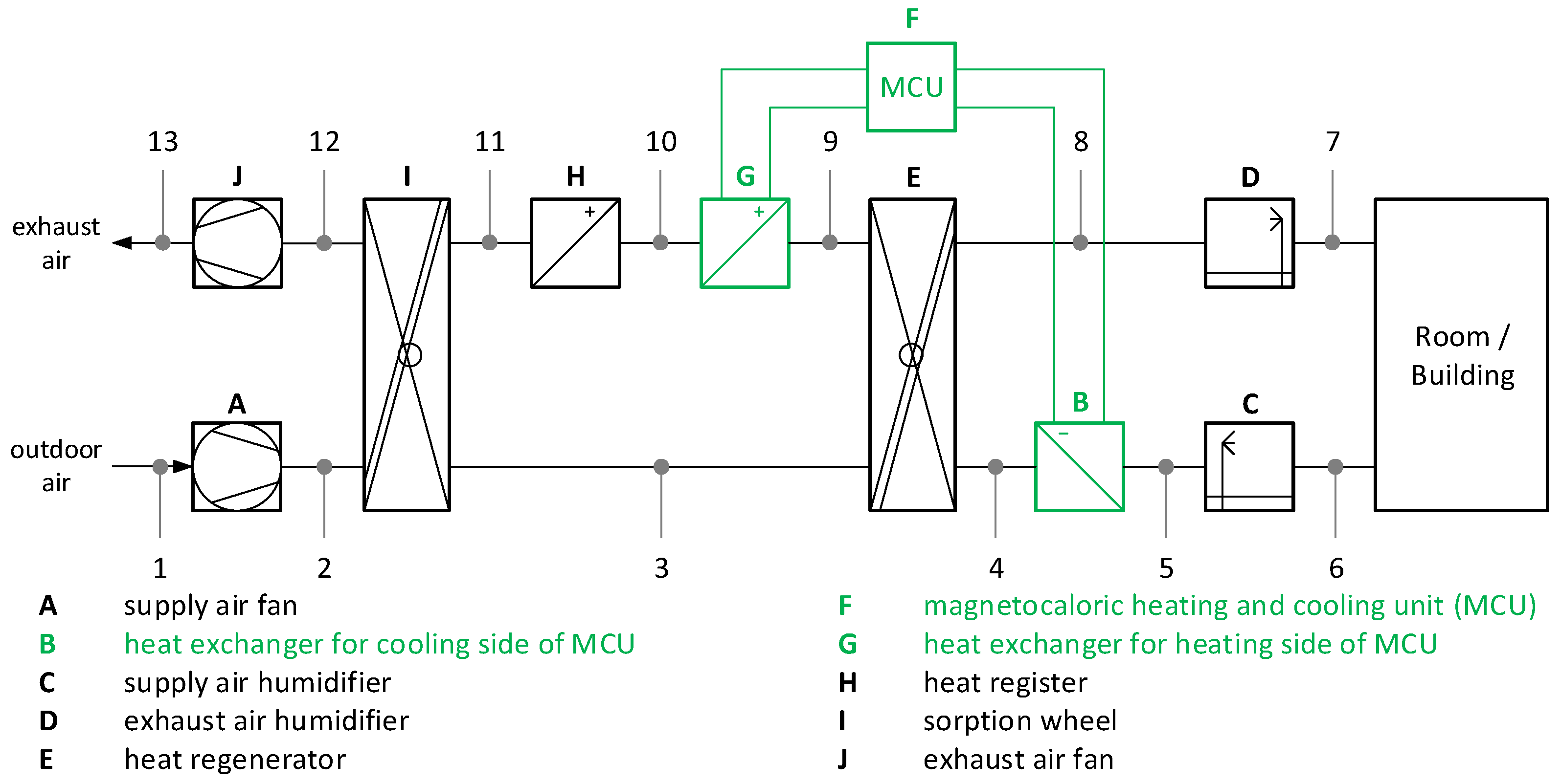
In our paper, we present a new perspective of how magnetocaloric devices can be used for energy-efficient cooling in such a way that the magnetocaloric cooling unit is not the stand-alone cooling unit itself, but one of the components in a DEC-device. Here, the magnetocaloric effect of the regenerator bed can be fully exploited, i.e., the heating and the cooling power generated supports either the humidifier or contributes directly to the total heating power of the DEC device. The aim of the Magnetocaloric heating and Cooling Unit (MCU) is to make the DEC process more flexible and to further increase the potential for integrating renewable energies in this technology. A modified circuit diagram with additional heat exchangers for the MCU can be seen in
Figure 1, marked in green.
As current overviews of previously-developed prototypes show [
9,
10], one of the main problems is to achieve a thermal performance related to the amount of magnetocaloric material used and at a sufficient temperature range. According to [
9], these prototypes can be divided into three main categories, which, however, refer to the type of magnetic field generation (linear reciprocating, rotary, or static). The way in which the thermal energy can be extracted from the magnetocaloric material, on the other hand, is less varied.
This article presents a complete system concept consisting of a suitable magnetic circuit, an alternative concept for the thermal management, which is currently investigated, the production of epoxy-bonded LaFeSiMn-based plates by tape casting, and an energetic evaluation. The results were documented during the research project SOMAK [
11]. It should be noted that the presented setup is a test rig in order to evaluate the material configuration and to validate the calculation model. Measurements are currently being carried out, and the results and the comparison with other MCU concepts will be presented in a subsequent publication.
2. Explanation of the DEC Process
The DEC process has been developed for air-conditioning, i.e., conditioning of the air with regard to temperature and humidity. It can be operated very well with regenerative energy sources. The basic structure of a DEC air-conditioning system can be seen in
Figure 1.
The main parts of the system are the sorption wheel (I), the heat regenerator (E), the humidifiers (C/D) installed on the supply and exhaust air side, and the heat register (H) for regeneration of the sorption wheel on the exhaust air side. The individual process steps of the air through the standard DEC process are briefly described here [
2]. The outside air is aspirated by the fan (A) and first dried via the water-absorbing material of the sorption wheel (I). This releases adsorption heat so that the supply air leaves the wheel heated and with significantly lower absolute humidity. In the next step, the supply air is pre-cooled by means of the heat regenerator (E). The heat is transferred to the exhaust air. Afterwards, an adiabatic cooling takes place by evaporation within the humidifier (C). The supply air, which is now cooled compared to the outside air, but not too humid, can be used to cool a room or building.
The exhaust air is led through another humidifier (D) and cooled further by evaporation cooling. It is now saturated with moisture. In this way, the exhaust air is suitable for absorbing the heat energy stored in the heat regenerator from the supply air, while at the same time, the relative humidity drops significantly. The exhaust air is further heated by an external heat source (H), e.g., solar system or unused district heating. The now hot and very dry exhaust air serves to regenerate (dry) the sorption wheel so that the process cycle is closed. This makes the DEC process an extremely effective method of air-conditioning, which can, however, reach its limits in warm and at the same time very humid weather (such as summer thunderstorms).
To make the DEC system more flexible, the processes taken advantage of, which leads to a further lowering of the temperature after heat recovery or (at the same time) provides preconditioning for the regeneration of the sorption wheel. The aim is to reduce the temperature on the supply air side (Point 4 in
Figure 1) and to increase it on the exhaust air side (Point 9) by an MCU. As a result, the supply air temperature through the humidifier (C) can be reduced even further than with the standard DEC process, and heating energy is saved on the heat exchanger (H) side.
3. Concept and Design of the Magnetic Field Source
A high change in the magnetic flux density inside the MCmaterial is necessary to produce a sufficient change in the temperature of the MC material. Thereby, the generation of the magnetic fluxes should be very effective to ensure low acquisition and operation costs.
High magnetic field strengths are necessary to ensure the desired flux strengths, as the material chambers yield to large air gaps inside the magnetic circuit of the field generation unit. Sufficiently large magnetic fields inside the air gap can be generated by electrical coils; however, induction heating and large power consumption during operation decrease the efficiency of the whole system. Therefore, in this work, permanent magnets will be used to generate the magnetic fluxes.
3.1. Structural Basis of the Magnetic Circuit
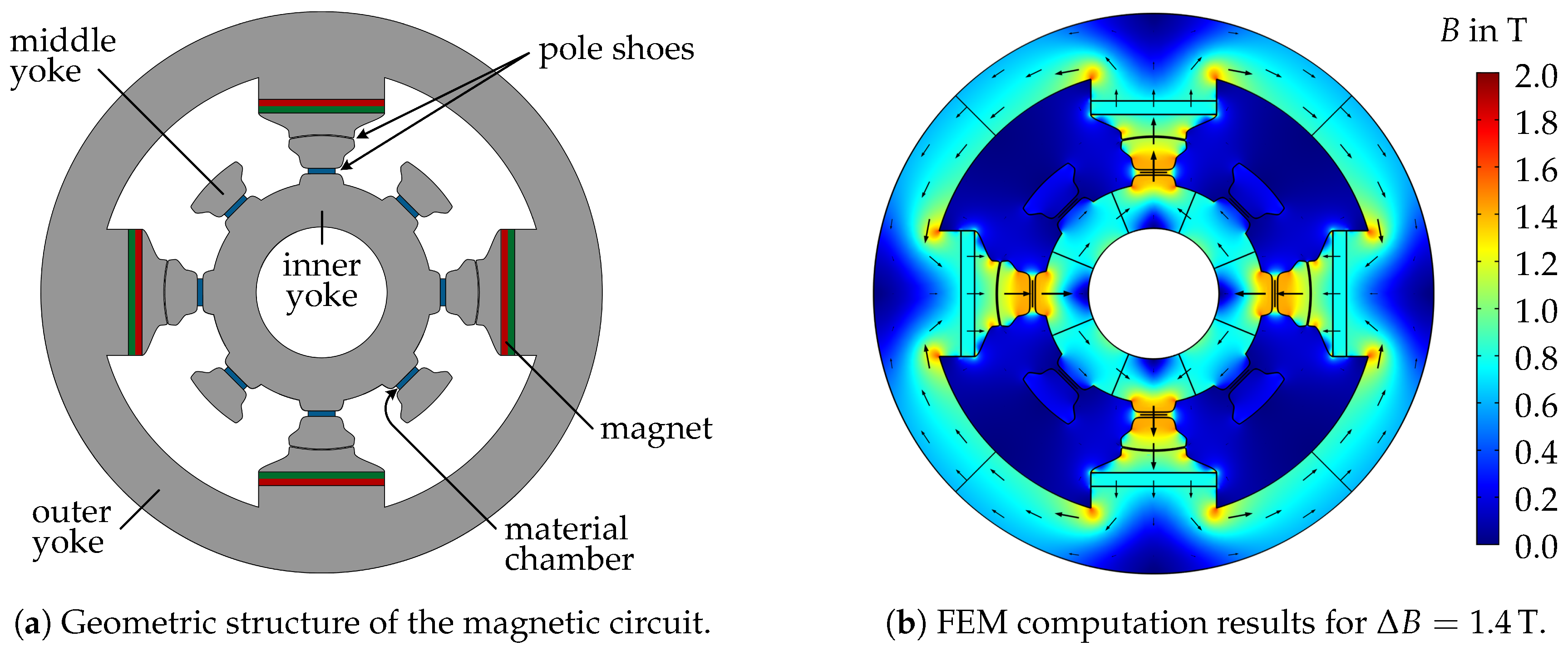
Figure 2a shows the design of the magnetic circuit. It is capable of generating magnetic flux densities of more than
inside the material chambers, while using a small amount of magnets. Other design concepts, e.g., [
12], yield higher flux densities by using Halbach arrays. However, such arrangements require far more permanent magnets, which need a special geometry.
The material chambers are placed in the stator, which consists of an inner and several middle yokes. The unit of magnets (Type N50), pole shoes, and outer yoke form the outer rotor, which generates and changes the magnetic fluxes.
The operation of the field generator is explained by considering the flow of the magnetic fluxes. Poles’ shoes on the magnets concentrate the generated flux densities, which afterwards pass the rotor/stator air gap. The middle yokes compress the flux densities further, which permeate the material chambers and are guided to the inner yoke. The magnetic fluxes of all branches are compensated in the inner and outer yokes, due to the opposite orientation of the magnets.
Figure 2b shows the computed magnetic flux density inside the magnetic circuit. By rotating the outer rotor around
, the magnetic flux density inside the material chambers is changed. During the rotation, the pole shoes of the magnets move from their current middle yoke to the neighboring one. Hence, the magnetic fluxes commutate from the currently permeated to the non-permeated material chambers. Regarding
Figure 2, there are eight material chambers, each containing ≈60
MC material. During one
rotation, four chambers are magnetized, and four are demagnetized.
3.2. Optimization of Pole Shoes and Permanent Magnets
The achievable change of the magnetic flux density inside the MC material strongly depends on the design of the magnetic circuit. In order to make effective use of the permanent magnets, their dimensions have to be optimized. Applying FEM-computations and using an optimizing algorithm, the optimal width of the magnets:
is determined. Using
and the corresponding height
yields the best utilization of magnets with the size
.
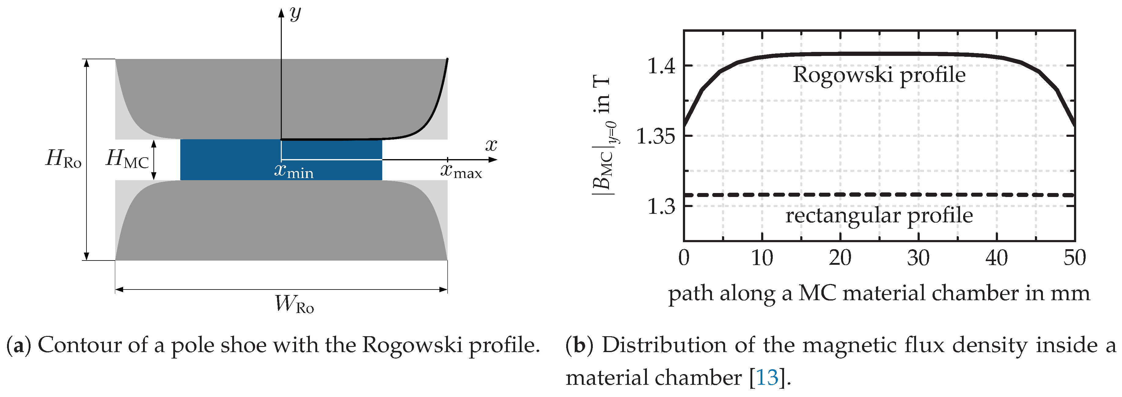
The contour of the pole shoes around the material chambers have a strong influence on the magnetic flux density inside the MC material. If the contour of the pole shoes was rectangular, high field distortions at the corners would appear and cause lower field strengths inside the MC material. Rounding the corners reduces the field distortions; however, the lowest field distortions appear by using a Rogowski profile. Rogowski derived this contour in [
14] to minimize the electric field distortions at the corners of capacitors. Since charge-free electrostatic and current-free magnetic problems are described by the same kind of partial differential equation, it is also applicable to minimize the magnetic field distortions at the corner of the pole shoes.
Figure 3a shows the contour of the Rogowski profile, which is generated by using Equations (
3)–(
5).
The comparison of the Rogowski profile to the rectangular pole shoe geometry in
Figure 3b shows an increase of more than 7% in the magnetic flux density inside the MC material.
4. Fluid Control and Thermal Management
Extracting the heating and cooling energy out of the magnetocalorical material is one of the main tasks on the way to an energy-efficient demonstrator. It is therefore important to exploit the thermal potential generated by the (de-)magnetization of the magnetocaloric material in the best possible way. It must be weighed between the target criteria of:
maximum performance (MCU heating and cooling power),
beneficial temperature level (for the DEC process:
and
[
11]),
the minimum auxiliary energy (focused for now on pump energy consumption caused by the pressure drop of the magnetocaloric material geometry; later also energy consumption by the magnetic circuit is necessary).
This opens up an efficient supply for a connected energy consumer.
Most of the actual prototypes deploy an Alternating Magnetocaloric Regenerator (AMR) to extract the heating and cooling energy from the magnetocaloric material [
3]. AMR is a discontinuous process based on the alternating flow through the material chamber and the respective removal of a partial volume whose temperature level can be used by a consumer. On one side of the material chamber, the heat can be extracted; on the other side, heat must be supplied (cooling side). In [
15], a numerical model is described that allows it to calculate the performance of an AMR. However, a number of deficits are associated with this AMR concept. The discontinuity and the change of the flow direction require a relatively complex effort regarding the necessary pump and valves. The displaced fluid should neither be too large, nor too small, otherwise the performance will decrease. Furthermore, the consumers must take the useful energy of the AMR directly at the fluid openings of the material chamber, since further internal fluid transport is not possible due to the change in the flow direction.
That is why an alternative concept is being tested in the presented project.
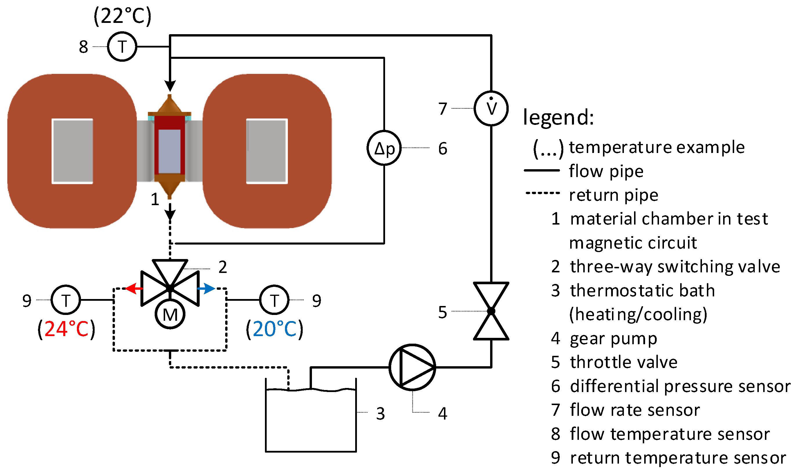
Figure 4 shows the scheme of a test stand that will enable a performance analysis of this concept. The principle is as follows: The heat transfer fluid flows in one direction through the material chamber containing the magnetocaloric material. The inlet temperature of the heat transfer fluid into the chamber corresponds approximately to the transition temperature of the material. By constant rotation of the outer rotor of the field source, a sequence of warm and cold fluid is generated by each magnetization or demagnetization of the magnetocaloric material, respectively. After having passed through the material chamber, the pulse sequence will be separated either in a warm or a cool fluid reservoir. These separated flow rates could be used by energy consumers in a subsequent application on the positions of temperature sensors (Number 9 in
Figure 4). For the investigations, the thermal sink, respectively source, is replaced by a thermostatic bath to control a constant flow temperature, as shown in
Figure 4. The aim is to measure the achievable temperature difference for the flow in the given case.
This concept needs a well-tuned control management. First of all, the timing between the magnetization state and the position of the three-way valve separating the warm and cold fluid has a large impact on the separation of the flow rates. In addition, the temperature difference of the magnetocaloric material decreases over time due to the heat transfer to the fluid after the magnetization state has changed. Finally, the heat capacities between the material and the fluid need to be balanced in order to obtain a small temperature difference during heat transfer so that the thermal potential of the magnetocaloric material can be fully exploited.
The advantage of this concept in contrast to the AMR lies primarily in its continuous operation. In principle, the achievable temperature difference decreases, but the volume flow is constant and potentially higher. Since both parameters are directly proportional in the calculation of the heat flow, both concepts are pursued in the current project. However, as the AMR concept is already sufficiently described, it will not be discussed further in this article.
5. Production of Epoxy-Bonded LaFeSiMn-Based Plates by Tape Casting
Two material classes are considered to be commercially suitable for room-temperature application: the Mn-Fe-P-Si-based Fe
-P-type alloys, mainly patented by BASF (e.g., in [
16,
17,
18]), and the La-Fe-Si-based NaZn
-type alloys that can be purchased from Vacuumschmelze GmbH & Co., KG. (Sigma Aldrich offers Gd
Si
Ge
powder and ingots (
https://www.sigmaaldrich.com/technical-documents/articles/materials-science/metal-and-ceramic-science/magnetocaloric-materials.html); however, the price is a factor of 20–40 higher compared to0 La-Fe-Si from Vacuumschmelze (Sigma Aldrich price list from 4 October 2018).) An overview of recent material developments can be found in [
4,
19,
20,
21]. In order to shape these materials into plates for regenerator beds, several attempts have been presented in recent publications, e.g., in [
22,
23,
24,
25]. Since fluid maldistribution is detrimental to heat transfer from the plates to the heat-transfer medium, stacking of these plain plates to a regular regenerator assembly remains one of the biggest challenges up to now. In this paper, we demonstrate a technology for the production of profiled La(Fe, Si, Mn)H-composite plates based on tape casting is presented in
Section 5. By introducing a profile on the plates, a regular heat-transfer cross-section within the production tolerances can be realized, and stacking of the plates is facilitated at the same time.
Tape casting is a casting process to produce flat sheets of a functional material, usually ceramics plates or films. A slurry, containing the functional material as powder together with liquid binders and solvents, is spread by a doctor blade on a flat substrate. After a drying process where the binder and solvents are eliminated, the sheet can be lifted from the substrate. By varying the distance between the substrate and the doctor blade, the sheet’s thickness can be adjusted. In our study, we chose an epoxy “SpeciFix” from Struers GmbH) serving as a liquid binder and after curing as a ductile matrix to dampenthe volume change of the magnetocaloric particles and prevent them from cracking.
5.1. Experimental Section
For the tape casting of the plates, hydrogenated LaFe
Si
Mn
powder was used. First, a pre-alloy was cast and heat-treated to adjust the magnetocaloric phase at 1373 K for seven days, followed by water quenching. After this step, the alloy is crushed into pieces and subjected to a vibration mill to produce irregularly-shaped powder with a particle size < 250
m. This powder is then hydrogenated under 0.9 bar hydrogen atmosphere at 300 K in order to saturate the hydrogen content. In previous publications, it was shown that partial hydrogenation leads to a separation into two hydrogen contents when the samples are stored around their transition temperature. As a solution, the combination of Mn and full hydrogenation was suggested to circumvent this aging effect while being able to tune the magnetic transition near room temperature [
26,
27]. The hydrogen content was evaluated by the hot-extraction method. The hydrogenated powder was mixed with 10 wt% epoxy and then poured onto a PTFE substrate plate with parallel notches of 0.5 mm in thickness, and the distance between the notches was 1 mm. The LaFeMnSi-epoxy-mixture was covered by a Cu-foil and subsequently spread by the doctor blade with a velocity of 2.5 mm s
. The distance from the PTFE plate and the doctor blade was 0.5 mm. With a density of the epoxy of 1.1 g cm
and of 7.3 g cm
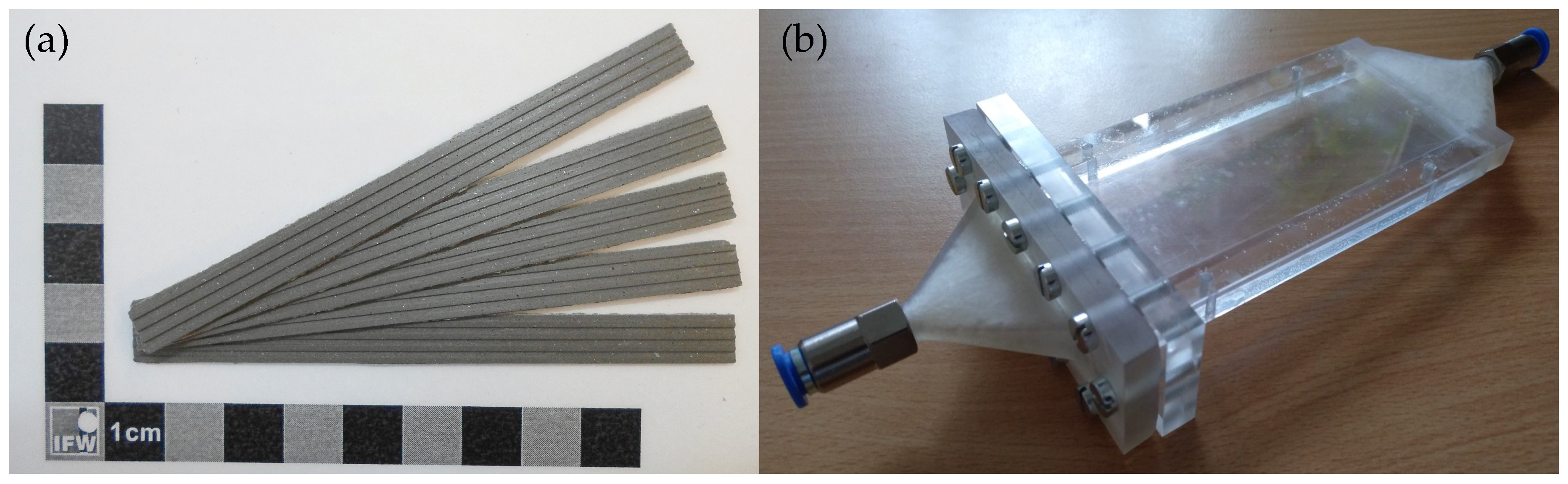
, the volume-fraction of the LaFeMnSi-epoxy-mixture can be estimated to be (55:45) vol%. After curing, the composite plate is removed from the substrate and cut into strips of 8 mm in width and 100 mm in length to fit into the material chamber, as can be seen in Figure 7a in
Section 6. In order to monitor the magnetic properties after each preparation step, magnetic measurements were performed in a magnetic property measurement system (Quantum Design MPMS-XL). Temperature-dependent magnetization was measured at a temperature sweep rate of 2 K min
in µ
T. The entropy change was calculated from field-dependent magnetization curves by applying the Maxwell relation. Isothermal
-curves were measured at temperatures near the transition temperature. The magnetic field was varied from 0–2 T for each temperature in oscillate mode, and magnetization was recorded in 0.1-T settle point steps.
5.2. Optimal Particle Fraction
In the first step, the particle size distribution of the magnetocaloric powder was optimized, since it affects both the tape casting process and the magnetocaloric properties of the composites. For this purpose, the ternary alloy, LaFe
Si
, prepared as in [
28] was used. According to a number of investigations [
29,
30,
31,
32,
33], a particle size larger than 150
m seems to be best suited since magnetocaloric performance is most similar to bulk material compared to smaller particle sizes. However, in order to produce plates with a 500-
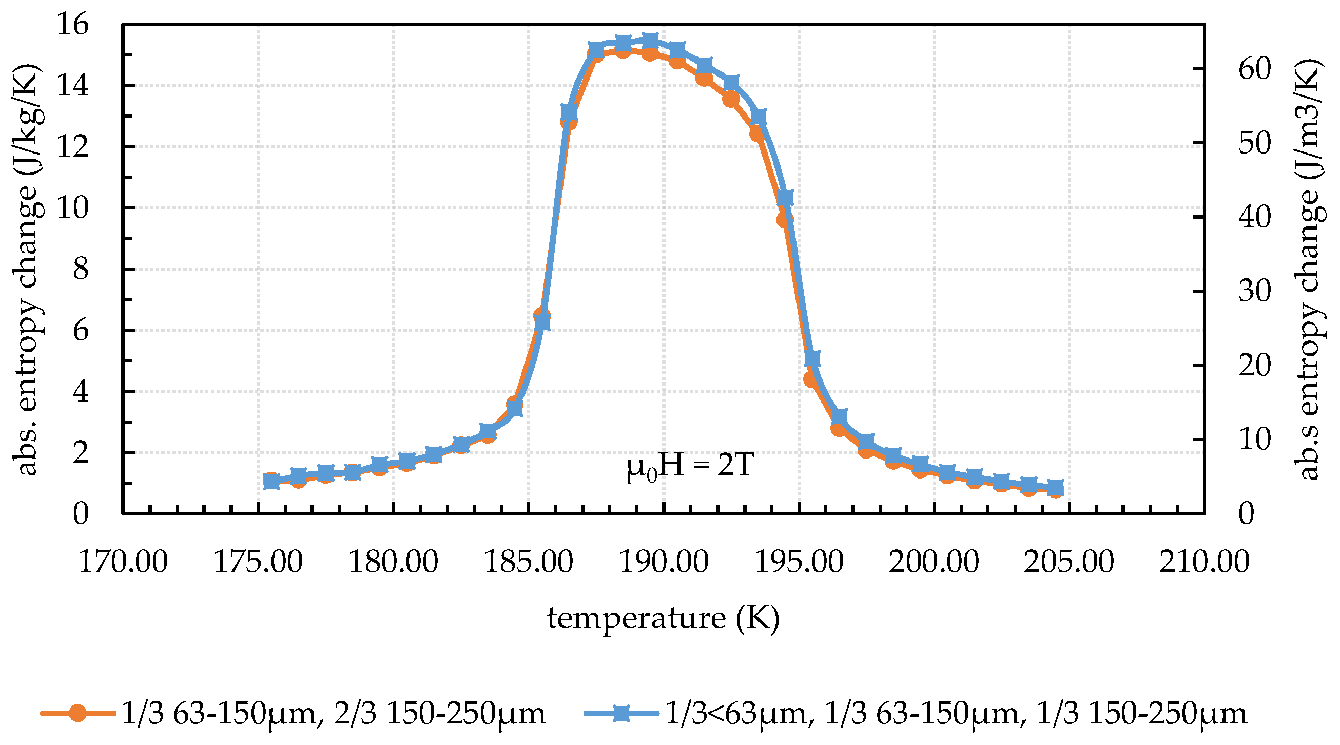
m thickness, such large particles are detrimental to the filling factor in the composite plate, since interparticle spaces are not filled by smaller particles. Moreover, spreading is very difficult, i.e., homogeneously-dense plates cannot be produced. In order to enhance the processability while a large magnetocaloric effect is retained, composite plates with two different particle size distributions have been produced. The combination of fractions was as follows: 33 wt% 63–150-
m particles together with 66 wt% 150–250-
m particles and 33 wt% <63
m together with 33 wt% 63–150-
m and 33 wt% 150–250-
m particles. The epoxy content of 13 wt% (corresponding to 50 vol%) was kept constant. From
Figure 5, it is visible that the sample with 33 wt% 150–250
m shows the same entropy change as the sample with 66 wt% 150–250-
m particles. The magnetocaloric effect, therefore, is not affected by smaller particles, which can be understood since the volume fraction of small particles has not increased much. For the further tape casting process, therefore, the combination of particle fractions 33 wt% <63
m, 33 wt% 63–150
m, and 33 wt% 150–250
m was chosen, since spreading was much easier than with 66 wt% large particles.
5.3. Properties of Starting Material and Profiled Plates
In
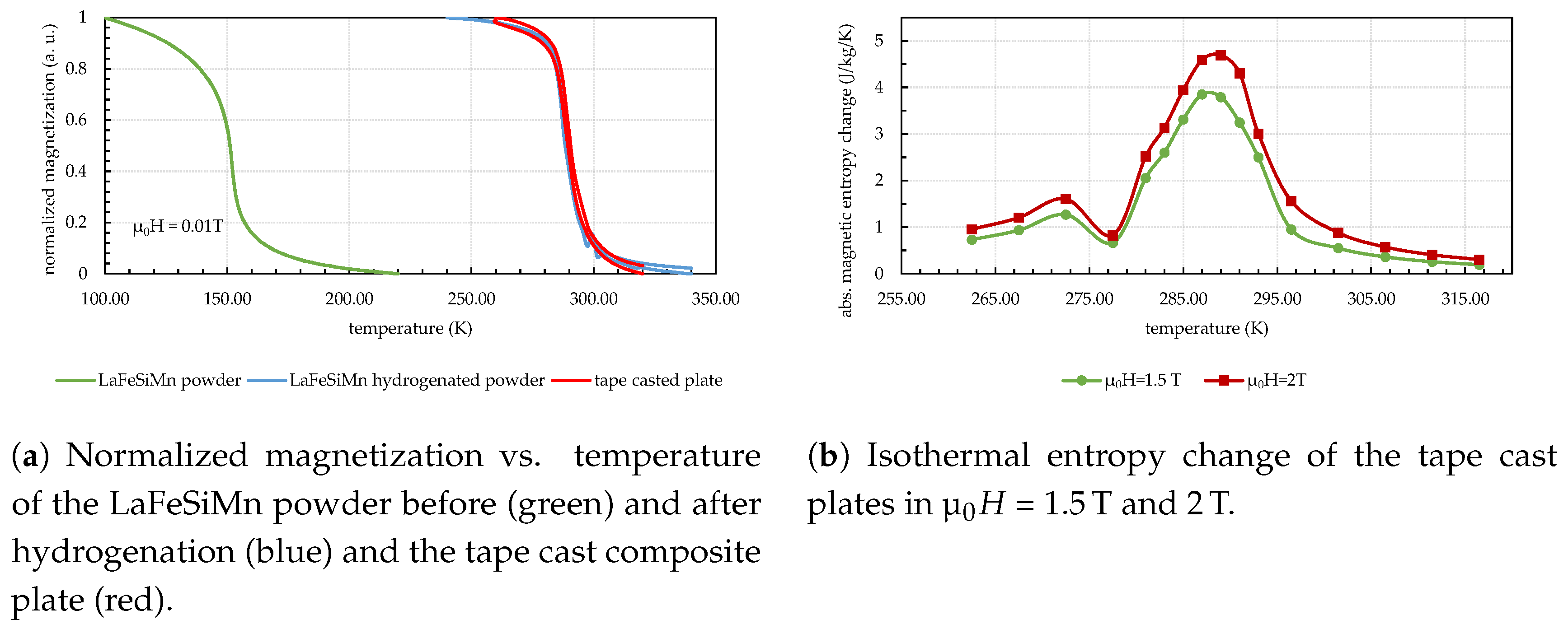
Figure 6a, the temperature-dependent magnetization of the starting material LaFe
Si
Mn
, of the hydrogenated powder LaFe
Si
Mn
H
, and the processed tape cast plate is shown. As can be seen, the transition temperature is shifted by hydrogenation from 152 K to 288 K. Moreover, the transition temperature is stable after tape casting, indicating that the curing process has no considerable impact on the hydrogen content of the material. The entropy change of the tape cast plate is shown in
Figure 6b and is only slightly smaller than compared to
reported for hydrogenated Mn-doped alloys in that temperature range [
26,
27]. We believe that this reduction can be attributed to the magneto-volume effect that appears in bulk samples, but is hindered in composites due to the epoxy.
6. Performance Evaluation
The following sections show an excerpt of the results from [
11]. To evaluate the performance of a magnetocaloric sample geometry, the following simplified efficiency definition (at this point, the so-called coefficient of material performance) is used:
The assessment is based on a simple benefit-to-expenditure analysis to make the different geometries comparable. The valuation parameter contains only those parameters that are directly attributable to the material and the geometry. Other auxiliary energies (e.g., the magnet field) or losses (e.g., thermal losses, pump efficiency) are not taken into account.
Section 6.1 and
Section 6.2 show the calculation of the necessary pump power
and the thermal output
, respectively.
Section 6.3 presents the energy-saving potential when using a magnetocaloric device for DEC air-conditioning. All calculations were made for a geometry of the material chamber, as can be seen in
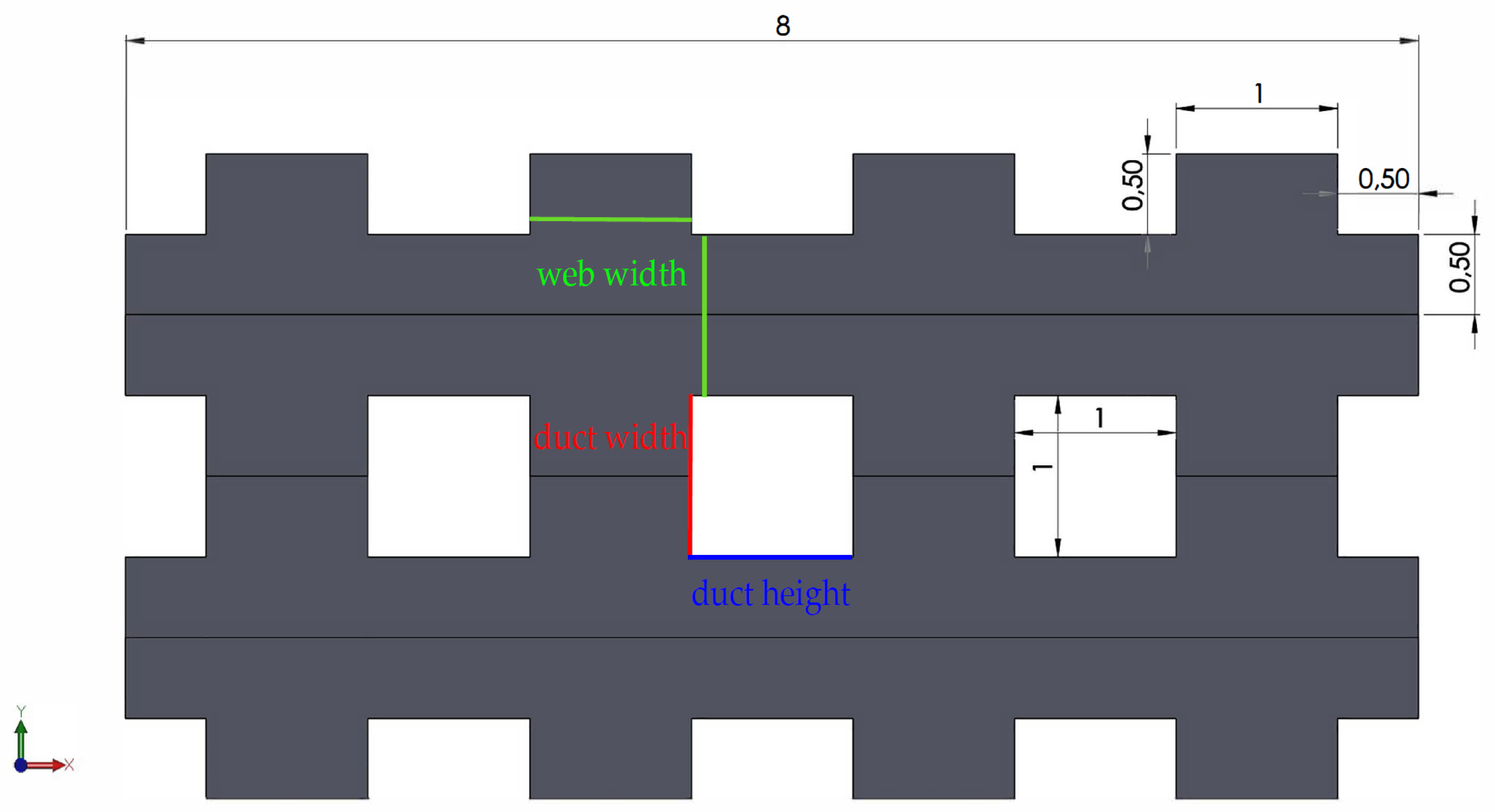
Figure 7b. Other geometries such as plates and spherical fills will, however, be taken into account in the project. The free-flow cross-section measures a height of 8 mm and a width of 48 mm over a length of 100 mm. Inside, the profiled plates (see
Figure 7a) are stacked, as shown in
Figure 8 to build a grid flow with duct dimensions of 1 mm each.
6.1. Hydraulic Performance
Using the example of profiled plate grids, the evaluation of the hydraulic behavior by calculating the pressure drop
caused by the sample geometry is shown in the following. With
, it is possible to determine the pumping power
using (
7). By this, it is possible to estimate the necessary auxiliary energy while neglecting the pump efficiency.
To calculate the pressure drop normalized to the length
of a grid flow, an approach based on [
34] is used.
With (
8), the pressure drop caused by a profiled plate grid can be calculated for different duct geometries while adjusting the duct’s width, height, and its number.
6.2. Thermal Performance
The thermal performance is calculated under the following boundary conditions:
The material changes temperature by 3 K when the magnetic state changes.
The fluid is propylene glycol, as water might favor corrosion of the material.
Measurements with the test stand (see
Figure 4) to evaluate the following calculations are currently being planned. Generally, the thermal output
of the magnetocaloric material in a material chamber is calculated according to the following equation:
with:
temperature immediately after the change of magnetic state
temperature immediately before the next change of magnetic state
t time between two changes of the magnetic state.
The time t for changing the magnetic state is set to the higher value of:
Following the boundary conditions described at the beginning, the temperature difference
is set to 3 K.
Figure 9 shows the thermal output and its efficiency for different dimensions of the profiled plates. The web width and the duct width/height (see
Figure 8) were varied including the current plate geometry with 1 mm in each dimension.
Basically, it should be noted that the achievable thermal performance
increases with increasing flow rate
, while the coefficient of material performance
decreases. This is due to two reasons: On the one hand, the time for the full heat transfer (see No. 2 above) is relatively long at low flow rates due to the low resulting heat transfer coefficient. On the other hand, a low flow rate also means a low flow velocity on which the resulting pressure drop is quadratically dependent (see Equation (
8)). This means that the resulting pump power
decreases disproportionately with decreasing flow rate. As a result,
goes to infinity for flow rates close to zero, but the achievable thermal performance is also close to zero. Therefore,
Figure 8 only shows the results with a volume flow of
L min
.
It can be seen that smaller ducts generate a larger thermal output due to the higher fluid velocity and a better heat transfer from the material to the fluid. Simultaneously, the pressure difference increases, so that the maximum efficiency is given for small flow rates and larger, square duct cross-sections. These limits show that there needs to be a trade-off between these two parameters, heat transfer and pressure drop, in order to exploit the energetic potential maximally. Moreover, the integration of other auxiliary energies, e.g., for the magnetic circuit, is necessary for further consideration.
6.3. Energy Saving of a DEC-Device
The heating and cooling capacity, which is dissipated by the magnetocaloric material, is transmitted to the supply and exhaust air volume flow of the DEC air-conditioning system by means of a heat transfer medium and a heat exchanger (see
Figure 1). In order to detect the thermodynamically necessary operating parameters of the MCU, a calculation tool was developed in [
35] to calculate the status points of the extended DEC air-conditioning system process depending on various outside and supply air conditions, as well as room loads. The notified power range of the MCU is determined with the help of the calculation tool under the following boundary conditions for summer:
cooling and heating capacity of the MCU are identical
outside air:
,
(design recommendation by VDI2078 [
36])
room air: , ,
room load: office room with three users and PCs (, )
Normally, DEC air-conditioning systems are designed for rooms with significantly higher loads (e.g., concert/lecture halls). The present example is scaled down to the target performance (
kW) from a material chamber, as shown in
Figure 9.
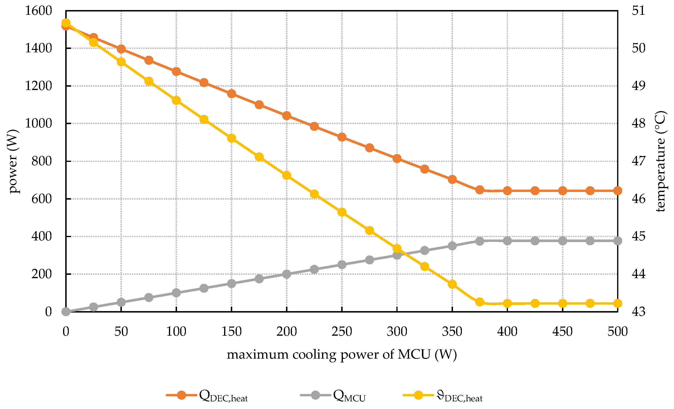
Figure 10 shows the influence of the MCU power (as cooling power on the supply air side and as heating power on the extract air side; see Components B and G in
Figure 1) on the remaining required heating power in the heat register of the DEC process. In addition, the relevant temperature after the heat register is shown (see Point 11 in
Figure 1). Without support from the MCU, the heat register needs a heating output of
W to dry the fresh air sufficiently so that subsequent cooling via the humidifiers is possible. With a limit power of
W for heating and cooling, the remaining, necessary heating output can be reduced to
W, which means a reduction of 58%.
This power saving is achieved in two ways: On the one hand, pre-cooling by the MCU reduces the necessary cooling capacity of the humidifiers. This means that the drying of the fresh air can be reduced, thus reducing the heating temperature and output . On the other hand, pre-heating by the MCU reduces the heating output directly. At the same time, a further increase in MCU power is not possible, as otherwise the supply air temperature would fall on , which could lead to uncomfortable room air conditions.
7. Summary and Conclusions
The present paper reports on the joint research activities between TUDresden and IFWDresden in the frame of a BMWifunded project “SOMAK”. The goal of this project is to evaluate the potential of a magnetocaloric heating and cooling unit that can be integrated in a DEC air-conditioning system in order to make the DEC process more effective. The first results that were achieved up to now can be summarized as follows:
A design of a rotating magnetic circuit with eight material chambers is shown.
The magnetic flux density in the magnetocaloric material is increased by 7% for pole shoes with a Rogowski profile instead of a rectangular geometry.
The magnetic flux density between the pole shoes is 1.5 T.
Three hundred grams of profiled epoxy-bonded plates with 55 vol% LaFeSiMnH were produced by tape casting and can be fit into the material chamber.
The plates show a maximum isothermal entropy change of 3.8 J kg K at a magnetic field change of 1.5 T at 285 K.
The theoretically-achievable thermal output for the considered material samples ranges from 50–300 W.
The efficiency reaches very high values of , taking only the pump auxiliary energy into consideration.
The energy saving potential can be up to 58% when an MCU is integrated as a boosting unit in comparison to conventional DEC air-conditioning systems.
The next steps include the testing of a single material chamber in the test stand presented in
Figure 4 containing different magnetocaloric materials, such as the profiled LaFeSiMn-based plates and Gd-plates, in terms of the achievable temperature span under zero load and to optimize operating conditions, such as temperature, fluid flow rate, and the synchronization of the switching valve separating the hot and cold fluid.
Author Contributions
Investigation, M.B., L.S., C.J., and M.K.; numerical simulation, M.B and C.J.; experiments M.B., L.S., C.J., and M.K.; writing, original draft preparation, M.B., L.S., C.J., and M.K.; writing, review, A.W. and J.S.
Funding
This research was funded by the German Research Foundation in the framework of SPP1599 “Ferroic Cooling” under Grant WA3294/3-2 (A.W.) and by the Germany Federal Ministry for Economic Affairs and Energy under Project Numbers 03ET1374A (C.J., L.S., M.B.) and 03ET1374B (M.K.).
Conflicts of Interest
The authors declare no conflict of interest.
Nomenclature
| Symbols | | |
| A | area | m |
| B | magnetic flux density | T |
| specific heat capacity | kJ kg K |
| f | cross-sectional area of the duct | m |
| H | height | m |
| L | length | m |
| m | mass of magnetocaloric material | kg |
| mass flow | kg s |
| p | pressure | Pa |
| P | electrical power | W |
| Reynolds number | − |
| thermal power | W |
| t | time | s |
| u | flow velocity | m s |
| U | circumference of the duct | m |
| flow rate | m s |
| W | width | m |
| x | absolute humidity | g kg |
| Greek | | |
| difference | − |
| coefficient of material performance | − |
| temperature | C |
| fluid density | gk m |
| coefficient for taking into account the aspect ratio of the duct | − |
| Subscript | | |
| 0 | beginning | − |
| cooling | − |
| desiccative evaporative cooling | − |
| heating | − |
| magnetocaloric | − |
| magnetocaloric heating and cooling unit | − |
| maximum | − |
| minimum | − |
| outside | − |
| permanent magnet | − |
| attributed to the pump | − |
| room | − |
| attributed to the supply side | − |
| at time t | − |
| water | − |
References
- Jani, D.; Mishra, M.; Sahoo, P.K. A critical review on application of solar energy as renewable regeneration heat source in solid desiccant—Vapor compression hybrid cooling system. J. Build. Eng. 2018, 18, 107–124. [Google Scholar] [CrossRef]
- Jani, D.B.; Gwalwanshi, M.; Mishra, M.; Sahoo, P.K. Solid Desiccant Cooling—An Overview. In Proceedings of the International Conference on Advances in Chemical Engineering, Roorkee, India, 22–24 February 2013. [Google Scholar]
- Kitanovski, A.; Tušek, J.; Tomc, U.; Plaznik, U.; Ožbolt, M.; Poredoš, A. Magnetocaloric Energy Conversion—From Theory to Applications; Springer International Publishing: Heidelberg, Germany, 2015. [Google Scholar]
- Franco, V.; Blázquez, J.; Ipus, J.; Law, J.Y.; Conde, A. Magnetocaloric effect: From materials research to refrigeration devices. Prog. Mater. Sci. 2018, 93, 112–232. [Google Scholar] [CrossRef]
- Premiere of Cutting-Edge Cooling Appliance at CES 2015. Available online: https://www.basf.com/en/company/news-and-media/news-releases/2015/01/p-15-100.html (accessed on 30 August 2018).
- Premiere of Revolutionary Medical Refrigerator with Cooltech Applications at Medica 2015. Available online: http://www.businesswire.com/news/home/20151214006059/en/Premiere-Revolutionary-Medical-Refrigerator-Cooltech-Applications-Medica (accessed on 30 August 2018).
- Fähler, S.; Rößler, U.K.; Kastner, O.; Eckert, J.; Eggeler, G.; Emmerich, H.; Entel, P.; Müller, S.; Quandt, E.; Albe, K. Caloric Effects in Ferroic Materials: New Concepts for Cooling. Adv. Eng. Mater. 2012, 14, 10–19. [Google Scholar] [CrossRef]
- Aprea, C.; Greco, A.; Maiorino, A.; Masselli, C. Solid-state refrigeration: A comparison of the energy performances of caloric materials operating in an active caloric regenerator. Energy 2018, 165, 439–455. [Google Scholar] [CrossRef]
- Yu, B.; Liu, M.; Egolf, P.W.; Kitanovski, A. A review of magnetic refrigerator and heat pump prototypes built before the year 2010. Int. J. Refrig. 2010, 33, 1029–1060. [Google Scholar] [CrossRef]
- Kitanovski, A.; Tušek, J.; Tomc, U.; Plaznik, U.; Ožbolt, M.; Poredoš, A. Overview of Existing Magnetocaloric Prototype Devices. In Magnetocaloric Energy Conversion; Springer International Publishing: Heidelberg, Germany, 2015; pp. 269–330. [Google Scholar]
- Seifert, J. Solare Magnetokalorische Klimatisierung von Gebäuden (SOMAK); Technical Report; TU Dresden/IFW Dresden/INNIUS GTF GmbH: Dresden, Germany, 2018. [Google Scholar]
- Lee, S.J.; Kenkel, J.M.; Pecharsky, V.K.; Jiles, D.C. Permanent magnet array for the magnetic refrigerator. J. Appl. Phys. 2002, 91, 8894–8896. [Google Scholar] [CrossRef]
- Jäschke, C.; Schegner, P.; Seifert, J. Design of an Efficient Magnetic Circuit for a Magneto-Caloric Air- Conditioning System. In Proceedings of the 2018 IEEE International Magnetic Conference (INTERMAG), Singapore, 23–27 April 2018. [Google Scholar]
- Rogowski, W. Die elektrische Festigkeit am Rande des Plattenkondensators: Ein Beitrag zur Theorie der Funkenstrecken und Durchführungen Ein Beitrag zur Theorie der Funkenstrecken und Durchführungen. Archiv der Elektrotechnik 1923, 12, 1–15. [Google Scholar] [CrossRef]
- Tusek, J.; Kitanovski, A.; Prebil, I.; Poredo, A. Dynamic operation of an active magnetic regenerator (AMR): Numerical optimization of a packed-bed AMR. Int. J. Refrig. 2011, 34, 1507–1517. [Google Scholar] [CrossRef]
- De Groot, R.A.; Brück, E. Method for Generating Giant Magnetocaloric Materials. U.S. Patent 2013/0175466A1, 7 November 2013. [Google Scholar]
- Guillou, F.; Brück, E.; Reesink, B.H. Magnetocaloric Materials Containing B. Patent WO2015/018705A1, 12 December 2015. [Google Scholar]
- Scharf, F.; Schwind, M.; Van Asten, D.; Jacobs, S.A. Magnetocaloric Cascade and Method for Fabricating a Magnetocaloric Cascade. Patent WO/2016/096509, 23 June 2016. [Google Scholar]
- Chaudhary, J.; Chen, X.; Ramanujan, R. Iron and manganese based magnetocaloric materials for near room temperature thermal management. Prog. Mater. Sci. 2019, 100, 64–98. [Google Scholar] [CrossRef]
- Brück, E.; Yibole, H.; Nguyen, V.T.; Miao, X.; Boeije, M.; Dijk, N.V. Transition Metal Based Magneto Caloric Materials for Energy Efficient Heat Pumps. Solid State Phenom. 2017, 257, 129–134. [Google Scholar] [CrossRef]
- Lyubina, J. Magnetocaloric materials for energy efficient cooling. J. Phys. Chem. 2017, 50, 053002. [Google Scholar] [CrossRef]
- Wieland, S.; Petzoldt, F. Powder-extrusion and sintering of magnetocaloric LaCe(FeMnSi)13 alloy. J. Alloys Compd. 2017, 719, 182–188. [Google Scholar] [CrossRef]
- Radulov, I.A.; Karpenkov, D.Y.; Skokov, K.P.; Karpenkov, A.Y.; Braun, T. Production and properties of metal-bonded La(Fe, Mn, Si)13Hx composite material. Acta Mater. 2017, 127, 389–399. [Google Scholar] [CrossRef]
- Zhang, H.; Liu, J.; Zhang, M.; Shao, Y.; Li, Y.; Yan, A. LaFe11.6Si1.4Hy/Sn magnetocaloric composites by hot pressing. Scr. Mater. 2016, 120, 58–61. [Google Scholar] [CrossRef]
- Engelbrecht, K.; Bahl, C.R.H.; Nielsen, K.K. Experimental results for a magnetic refrigerator using three different types of magnetocaloric material regenerators. Int. J. Refrig. 2011, 34, 1132–1140. [Google Scholar] [CrossRef]
- Barcza, A.; Katter, M.; Zellmann, V.; Russek, S.; Jacobs, S.; Zimm, C. Stability and Magnetocaloric Properties of Sintered La(Fe, Mn, Si)13Hz Alloys. IEEE Trans. Magn. 2011, 47, 3391–3394. [Google Scholar] [CrossRef]
- Krautz, M.; Skokov, K.P.; Gottschall, T.; Teixeira, C.; Waske, A.; Liu, J.; Schultz, L.; Gutfleisch, O. Systematic investigation of Mn substituted La(Fe, Si)13 alloys and their hydrides for room-temperature magnetocaloric application. J. Alloys Compd. 2014, 598, 27–32. [Google Scholar] [CrossRef]
- Krautz, M. Wege zur Optimierung Magnetokalorischer Fe-Basierter Legierungen Mit NaZn13-Struktur Für Die Kühlung Bei Raumtemperatur. Ph.D. Thesis, Techische Universität Dresden, Dresden, Germany, 2014. [Google Scholar]
- Lyubina, J. Recent advances in the microstructure design of materials for near room temperature magnetic cooling (invited). J. Appl. Phys. 2011, 109, 07A902. [Google Scholar] [CrossRef]
- Hu, F.X.; Chen, L.; Wang, J.; Bao, L.F.; Sun, J.R.; Shen, B.G. Particle size dependent hysteresis loss in La0.7Ce0.3Fe11.6Si1.4C0.2 first-order systems. Appl. Phys. Lett. 2012, 100, 072403. [Google Scholar] [CrossRef]
- Waske, A.; Giebeler, L.; Weise, B.; Funk, A.; Hinterstein, M.; Herklotz, M.; Skokov, K.; Fähler, S.; Gutfleisch, O.; Eckert, J. Asymmetric first-order transition and interlocked particle state in magnetocaloric La(Fe, Si)13. Phys. Status Solidi (RRL) Rapid Res. Lett. 2015, 9, 136–140. [Google Scholar] [CrossRef]
- Skokov, K.P.; Karpenkov, D.Y.; Kuz’min, M.D.; Radulov, I.A.; Gottschall, T.; Kaeswurm, B.; Fries, M.; Gutfleisch, O. Heat exchangers made of polymer-bonded La(Fe, Si)13. J. Appl. Phys. 2014, 115, 17A941. [Google Scholar] [CrossRef]
- Radulov, I.A.; Skokov, K.P.; Karpenkov, D.Y.; Gottschall, T.; Gutfleisch, O. On the preparation of La(Fe, Mn, Si)13Hx polymer-composites with optimized magnetocaloric properties. J. Magn. Magn. Mater. 2015, 396, 228–236. [Google Scholar] [CrossRef]
- Verein Deutscher Ingenieure. VDI-Wärmeatlas; Springer: Berlin/Heidelberg, Germany, 2013. [Google Scholar]
- Adam, P. Energetische Bilanzierung Einer Durch Eine Magnetokalorische Kühleinheit Erweiterten DEC-Klimaanlage; Project Work in a Research Internship; Technische Universität Dresden: Dresden, Germany, 2017. [Google Scholar]
- Verein Deutscher Ingenieure. VDI 2078: Berechnung der Kühllast klimatisierter Räume—VDI Kühllastregeln; VDI—Handbuch Raumlufttechnik: Düsseldorf, Germany, 1996. [Google Scholar]
© 2019 by the authors. Licensee MDPI, Basel, Switzerland. This article is an open access article distributed under the terms and conditions of the Creative Commons Attribution (CC BY) license (http://creativecommons.org/licenses/by/4.0/).

 ,
, 