Article

Pretreatment-Membrane Electrolysis Process for Treatment of Ammonium Sulfate Double Salt Crystals Formed During Electrolytic Manganese Production

1
School of Environmental and Municipal Engineering, Lanzhou Jiaotong University, Lanzhou 730070, China
2
Engineering Research Center of Ministry of Education for Comprehensive Utilization of Water Resources in Cold and Drought Areas, Lanzhou 730070, China
*
Author to whom correspondence should be addressed.
Crystals 2019, 9(12), 667; https://doi.org/10.3390/cryst9120667
Submission received: 23 October 2019 / Revised: 4 December 2019 / Accepted: 7 December 2019 / Published: 11 December 2019
(This article belongs to the Section Crystal Engineering)

Abstract

:
Ammonium sulfate double salt crystals (ASDSCs) are a by-product formed during the electrolytic production of manganese. The long-term open-air stacking of ASDSCs leads to the manganese and ammonia nitrogen present inside leaching with rainwater, which seriously damages the ecological environment. To find a reasonable treatment method, we developed a pretreatment-membrane electrolysis method, which allowed for the recycling of ASDSCs stepwise. At the beginning, the ASDSCs were dissolved in water. The Mn2+ and Mg2+ present in the crystals were converted into MnCO3 and MgCO3 and recycled for the production of electrolytic manganese. The filtered liquid (mainly ammonium sulfate) was electrically decomposed to generate ammonia water and sulfuric acid, which were recycled for electrolytic manganese production. The results show that under the optimal conditions of a current density of 300 A/m2—an electrolysis time of 11 h and a temperature of 40 °C—the decomposition rate of ammonium sulfate reached 98.4%. This method led to the complete decomposition and utilization of the ASDSCs and truly achieved the green electrolytic production of manganese.

1. Introduction

Ammonium sulfate double salt crystals (ASDSCs) are solid wastes produced during the production of electrolytic manganese. In recent years, China has become the largest country in electrolytic manganese production [1,2], accounting for 98% of the world’s total production capacity [3]. It is expected that the global demand for manganese will increase by 83% by 2021 [4]. According to the statistics of related electrolytic manganese enterprises, every 1 t of electrolytic manganese produced will produce 0.8–2.5 t of ASDSCs.
At present, the ore used by the electrolytic manganese production enterprise is manganese carbonate ore. Firstly, sulfuric acid is used to extract the Mn2+ ions, then a vulcanizing agent is added to remove impurities. The pH is adjusted by adding ammonia water and finally, the precipitate is removed by pressure filtration. At the same time, ammonium sulfate is formed, which can increase the conductivity of the solution and ensure that the pH of the solution is relatively stable. Since the solution is used in a closed loop, the Mg2+ present in the solution increase by ~2 g/L each cycle. In accordance with the common-ion effect, the solubility of manganese sulfate and ammonium sulfate in the electrolyte is reduced to form a mixed crystal. As the temperature decreases, the ions in the qualified liquid precipitate as crystals of ammonium sulfate manganese, and ammonium sulfate magnesium double salt crystals [5]. With the gradual increase of double salt crystals, electrolyte launders are easily blocked, which eventually affects the normal process of electrolysis. Therefore, ASDSCs need to be cleaned regularly. Most manganese plants transport the cleaned ASDSCs to a special solid waste dump for accumulation. A large number of ASDSCs piled up in the open air will be washed by rainwater and the NH4+ and Mn2+ in the crystals will dissolve out, which will seriously pollute the surrounding soil and water. In addition, the large amount of manganese contained in the crystals will also cause manganese waste if not recovered [6]. How to recycle the increasing ASDSCs has become an urgent problem for manganese-related enterprises and local governments [7]. At present, the treatment method for ASDSCs is mainly a step-by-step treatment. Ammonium persulfate and oxalic acid dihydrate are added for fractional precipitation [8]. CO2 is firstly introduced, then magnesium oxide is added to convert ASDSCs into magnesium sulfate crystals [5]. Some scholars have tried to combine the anode slag with ASDSCs for roasting and then water immersion solid-liquid separation [9]. However, the above methods have the problems of high energy consumption, high costs, complex processes, they require further treatment of the filtered products, and are without continuous utilization of the final filtrate, which cannot be applied to the actual industrial production. The common methods for removing ammonia nitrogen are air stripping [10], biological [11], ion exchange [12], chemical precipitation [13,14], and break point chlorination [15]. However, due to the complexity of the process, the difficulty of operation, the high operating cost, as well as the production of other substances that are difficult to utilize, it is not suitable for the step-by-step treatment of ASDSCs.
In order to solve the above problems, this paper proposes a new pretreatment-membrane electrolysis method to recycle ASDSCs into manganese carbonate, magnesium carbonate, sulfuric acid, and ammonia water, thus realizing the purpose of recycling ASDSCs. The method not only solves the problem that ASDSCs continuously accumulate and occupy land, and toxic and harmful substances leaching out and polluting the soil with rainwater, but it also brings economic benefits to electrolytic manganese production enterprises, saves the construction, maintenance, and management of slag fields and the production and transportation costs of sulfuric acid and ammonia water. After electrolysis, the weak liquid in the cathode chamber can be reused for the dissolution process of ASDSCs, and no new waste residue or waste liquid are generated in the treatment process, thus truly realizing green production. In this study, membrane electrolysis technology was first applied to the treatment of ASDSCs.

2. Materials and Methods

2.1. Materials and Reagents

The anode liquid in that electrolytic cell was a sulfuric acid solution, and the cathode liquid was a filtrate pretreated after the ASDSCs were dissolved in water. The chemical reagents used in the experiments were of analytical grade, and all solutions were prepared with deionized water with a resistivity greater than 18 MΩ cm. Fresh ASDSCs were provided by the Tianyuan Manganese Industry Group in Ningxia. The Inductively Coupled Plasma(ICP) analysis results of ASDSCs are shown in Table 1 and performance indexes of experimental membranes are given in Table 2.
The electrolytic cell had dimensions of 0.22 × 0.22 × 0.065 m3 and was made of epoxy resin. An anion-exchange membrane was utilized to sequentially divide the unit electrolytic cell into a cathode chamber and an anode chamber. The effective volume of each compartment was 500 mL. The effective membrane size of the ion-exchange membrane was 0.17 × 0.14 m2. The shape of the electrode plate was stable, and the anode was a 0.01147 m2 (0.14 × 0.105 m2) RuOx/IrOx-coated titanium electrode plate. The cathode plate was a stainless steel plate of the same area and was fixed at a distance of 0.04 m from the anode plate. A DC power supply (Shenzhen Mestek Electronics Co., Ltd., Shenzhen, China) was used, and the current and voltage ranges were 0–5 A and 0–32 V, respectively.

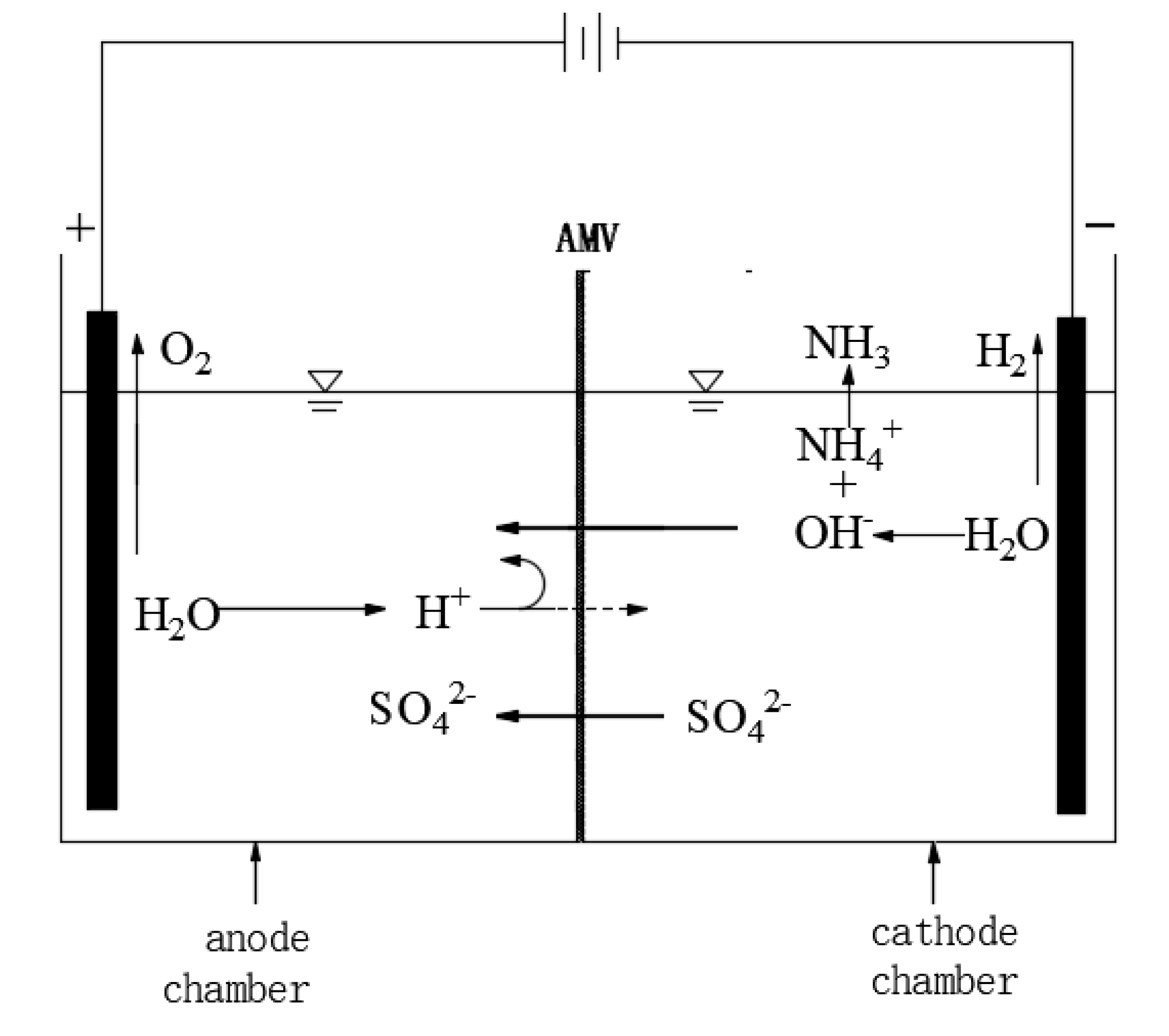
2.2. Experimental Principle

The implementation of the ion-exchange membrane electrolysis process relies primarily on the directional movement of anions through the anion-exchange membrane. Ion membrane electrolysis technology is a membrane application process with a DC electric field gradient as the main driving force. Apart from the electric field gradient, electrolysis is also affected by temperature and concentration [17,18].
The different aspects of electrolysis ion transport behavior include ion migration, water molecular electroosmosis, ion diffusion, etc. The possible ion transport process in the electrolytic cell is shown in Figure 1. Electrochemical processes include oxidation and reduction reactions. During the oxidation reaction, the oxygen evolution reaction occurred on the RuOX/IrOX-coated titanium electrode. Iridium oxides and ruthenium oxides are relatively active and stable catalysts for an oxygen release reaction under acidic conditions. Iridium oxide and ruthenium oxide are used as catalysts because iridium/ruthenium in their oxides contain a large amount of unsaturated ligands. Therefore, the possibility of forming iridium oxide and ruthenium oxide with the highest valence is reduced [19]. During the oxidation of H2O by mixed Ru-Ir oxides, the oxidation of H2O may be expressed in 3 steps:
IrOx/RuOx + H2O → IrOx/RuOx-(OH *) + H+ + e
IrOx/RuOx-(OH *) → IrOx/RuOx-O + H+ + e
2IrOx/RuOx-O → 2IrOx/RuOx + O2
NH4+ in the cathode chamber cannot migrate from the cathode chamber due to the barrier of the membrane. Sulphate concentration in the cathode chamber is several orders of magnitude higher than OH, so the charge balance across the membrane is mainly carried by SO42−, which is attracted by the anode to migrate from the cathode chamber to the anode chamber through the anion membrane and combines with the H+ generated by anode water electrolysis to generate H2SO4. Water is reduced into H2 and OH, and OH is combined with NH4+ to generate ammonia water. As the reaction continues, ammonia water is decomposed into NH3 and absorbed by the ammonia absorption tower. In addition, an ammonia evolution reaction may occur in the cathode. Specific electrochemical reaction formulas are shown in Equations (4)–(7).
Cathode chamber:
2H2O + 2e → H2↑ + 2OH
NH4+ + OH → NH3·H2O
NH3·H2O → NH3↑ + H2O
Anode chamber:
2H2O → 4H+ + O2↑+ 4e

2.3. Experimental Operation

The ASDSCs were dissolved in deionized water (one part ammonium sulfate double salt crystal and two parts water), and ammonia water was added to adjust the pH to 7.5. Then, 22 g of ammonium bicarbonate was added per liter of the solution, which was stirred for 20 min. Manganese was removed by suction filtration and adjusted to a pH of 9.5. Subsequently, 90 g of ammonium bicarbonate was added per liter of the solution and stirred for an additional 20 min. Then the magnesium was removed by suction filtration. The sequence of adding electrolytes into the electrolytic cell was as follows: 0.05 mol/L sulfuric acid solution was injected into the anode chamber and finally, the filtered liquid was injected into the cathode chamber. The electrolyzer was assembled with a water bath to heat and control the reaction temperature and a DC power supply was used for electrolysis. To study the effects of various experimental conditions on the treatment process in the system, experiments were designed with different electrode materials, varying the initial concentrations of acid in the anode chamber the reaction temperature, the current density, and the reaction time. Samples were withdrawn from the two compartments at certain intervals to observe concentration changes and two samples were analyzed at each point to obtain the average. After the experiment, the electrolyzer and membrane were washed with pure water for the next group of experiments.

2.4. Analysis Method

The concentration of ammonium sulfate in the cathode compartment was determined by the formaldehyde method and the acid concentration was measured by acid-base neutralization titration. Three samples were taken at each time point to calculate the average value. The main components of the ASDSC were measured by ICP and the slag filtered at each step was analyzed by X-Ray Diffraction(XRD).
Ammonium   sulfate   decomposition   rate =   1 c 2   ×   V c 1   ×   V  
where c1 is the initial ammonium sulfate concentration, c2 refers to the ammonium sulfate concentration after electrolysis for a period of time, and V is the volume of the liquid in the cathode compartment.

3. Results and Discussion

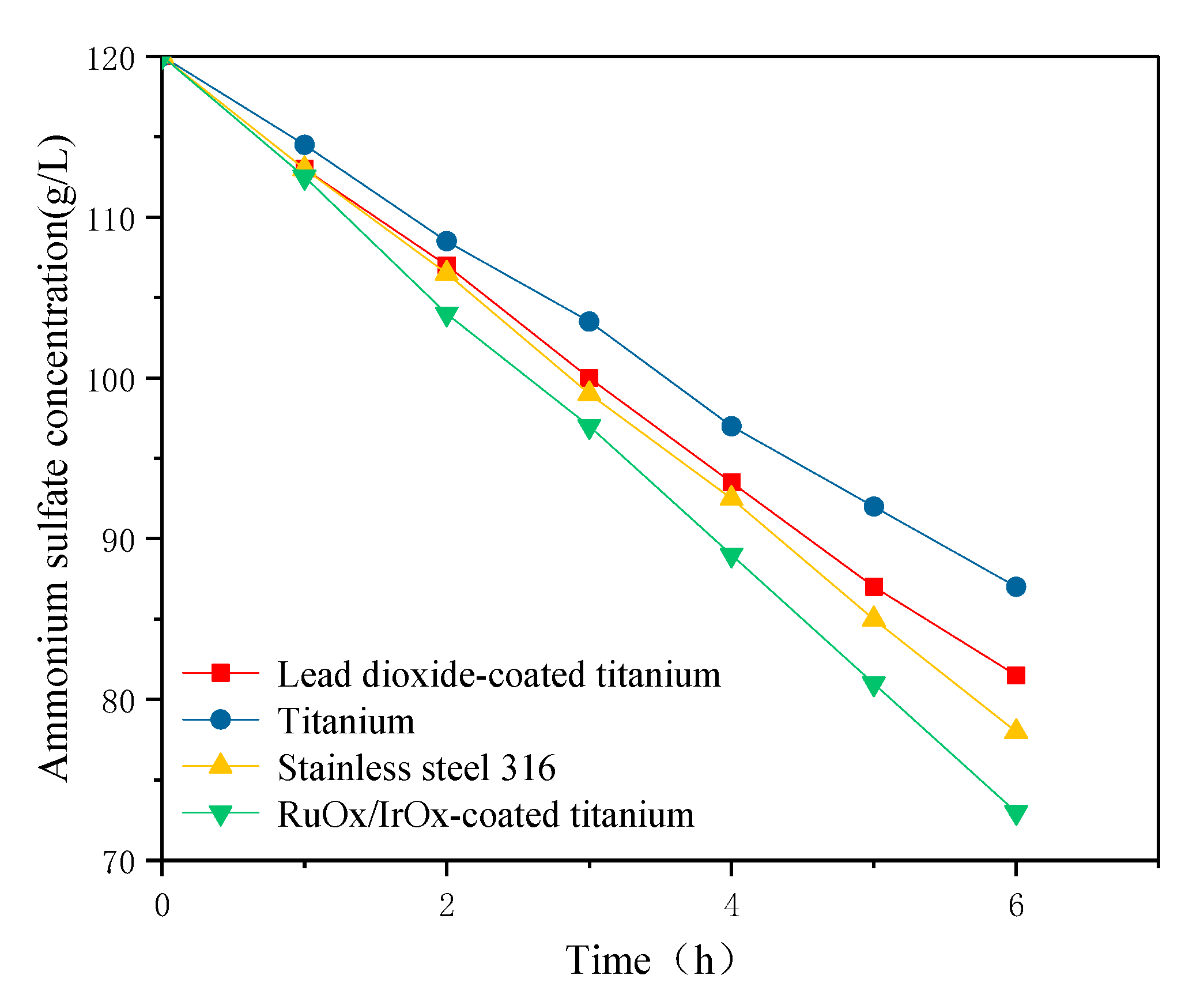
3.1. Effect of Different Electrode Materials

Because the electrolysis environment of the anode plate is a sulfuric acid environment, the RuOx/IrOx-coated titanium electrode has a strong electrocatalytic oxygen evolution capability, a good conductivity and corrosion resistance, a long service life, no anode slag generation, and the oxygen evolution potential of the RuOx/IrOx-coated titanium electrode plate is lower than that of the lead dioxide-coated titanium electrode, so it is used as the anode. The cathode uses lead dioxide-coated titanium, RuOx/IrOx-coated titanium, stainless steel and titanium electrodes. The effect of the four electrodes materials for the cathode on the decomposition rate of ammonium sulfate is shown in Figure 2. With an increase in the electrolysis time, the concentration of ammonium sulfate decreases continuously and the downward trend of the three membranes was similar. SO42− in the cathode chamber passes through the cathode membrane and enters the anode chamber. With the progress of the cathode hydrogen evolution reaction, the OH concentration in the cathode chamber increases continuously, and an increasing concentration of ammonia water is generated by being combined with NH4+, and the ammonia water will be decomposed into ammonia gas and water so the concentration of ammonium sulfate in the cathode chamber decreases continuously. Ammonium sulfate decomposes fastest when an RuOx/IrOx-coated titanium electrode is used as a cathode because an RuOx/IrOx-coated titanium electrode has the lowest overpotential and reaction (4) occurs at the cathode. When the titanium electrode is used as the cathode, the decomposition rate is the slowest, which is due to the poor electrocatalytic activity of the titanium electrode for water reduction. Only reaction (7) occurs at the cathode, so the ammonium sulfate concentration decreases slowly. In order to save costs, stainless steel 316 electrodes can be used in actual production.

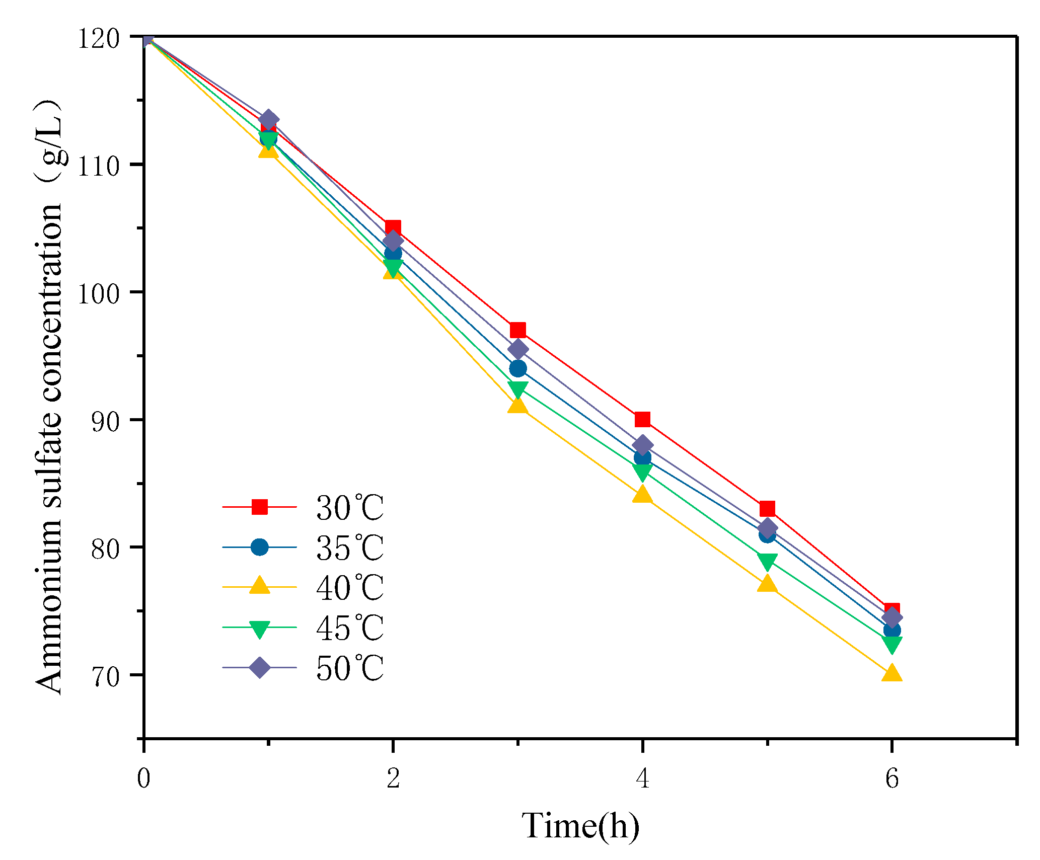
3.2. Effect of Temperature on Electrolysis

With the increase of electrolysis time and current density, the temperature of the solution will rise, which is due to the heat generated in the electrolysis process [20]. Thus, the temperature was controlled at 30, 35, 40, 45, and 50 °C in a water bath. Since high temperatures may damage the anion-exchange membrane, the highest temperature was set as 50 °C. The effect of different temperatures on the decomposition rate of ammonium sulfate in the cathode chamber is shown in Figure 3. The decomposition of ammonium sulfate was the fastest at 40 °C. The mass transfer system of the ion-exchange membrane in solution involved three parts: the migration of ions in the host solution, in the membrane, and in the boundary layer [21]. Under the applied electric field, owing to the different extent of ion transport in the membrane and solution, a concentration polarization occurred at the membrane and solution boundary. Zhang et al. [22] summarized through an Electrochemical Impedance Analysis(EIS) analysis that the thickness of the diffusion boundary layer decreased significantly with the increase of temperature, which was due to the increase of the ion migration rate in the solution by the temperature increase, thus enhancing the shielding effect of electrostatic force between the fixed charge groups and ions in the solution. At the same time, the change of physical properties, such as the swelling degree of the membrane material itself and the decrease of the Donnan effect caused by the increase of temperature, was also the reason for the decrease of the thickness of the diffusion boundary layer. Wang [23] et al. reported that temperature affected the ion migration rate and electrode surface electrochemical reaction rate. At a higher temperature, the solution resistance became smaller and the concentration polarization phenomenon was weaker, which led to a higher ion migration rate and consequently, a faster decomposition. However, a high temperature will lead to the decomposition of the function group of the anion-exchange membrane, resulting in an increase in the ion leakage rate, so the decomposition rate decreased slightly. The recommended temperature for electrolysis was 40 °C.

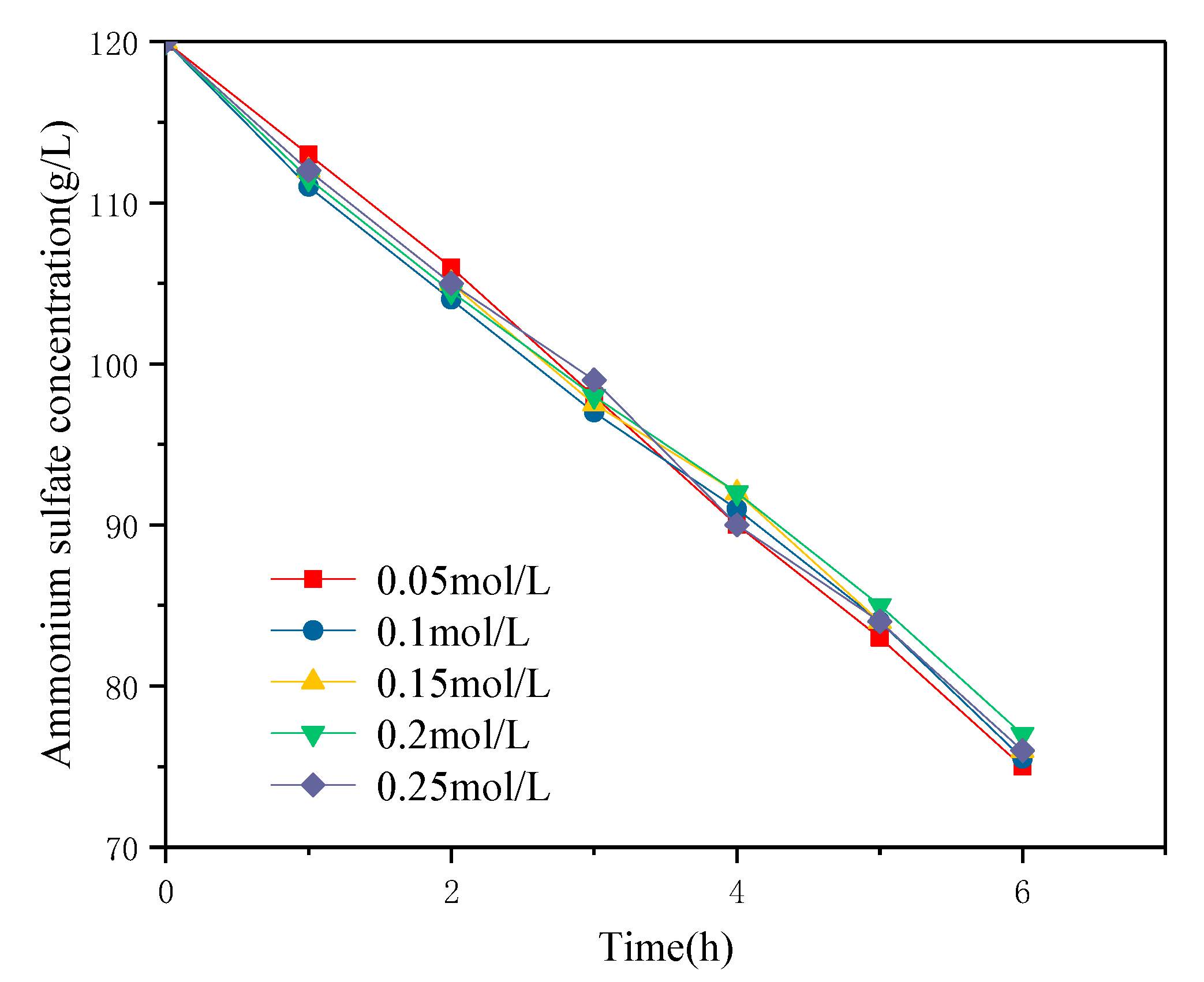
3.3. Effect of Initial Acid Concentration in the Anode Chamber

The effect of a different initial acid concentration in the anode chamber on the ammonium sulfate decomposition rate is shown in Figure 4. In the range of the initial concentration (0.05–0.25 mol/L), the initial acid concentration in the anode chamber had little effect on the ammonium sulfate decomposition rate. The EIS test results made by Zhang et al. [24] on the influence of concentration on the membrane showed that at a low concentration, the electrostatic attraction between the fixed charge groups and counter ions in the membrane was very strong, which limited the ion transport in the membrane, thus causing the resistance of the membrane to increase. Increasing the concentration of electrolyte solution would have a strong shielding effect on the electrostatic force (enhancing the conductivity of the ion-exchange membrane system) and would also reduce the thickness of the diffusion boundary layer of the ion-exchange membrane, thus reducing the total resistance of the ion-exchange membrane system. In the electrolysis process, increasing the acid concentration in the anode chamber did not impact the rate of electrical decomposition but only affected the magnitude of the operating voltage.

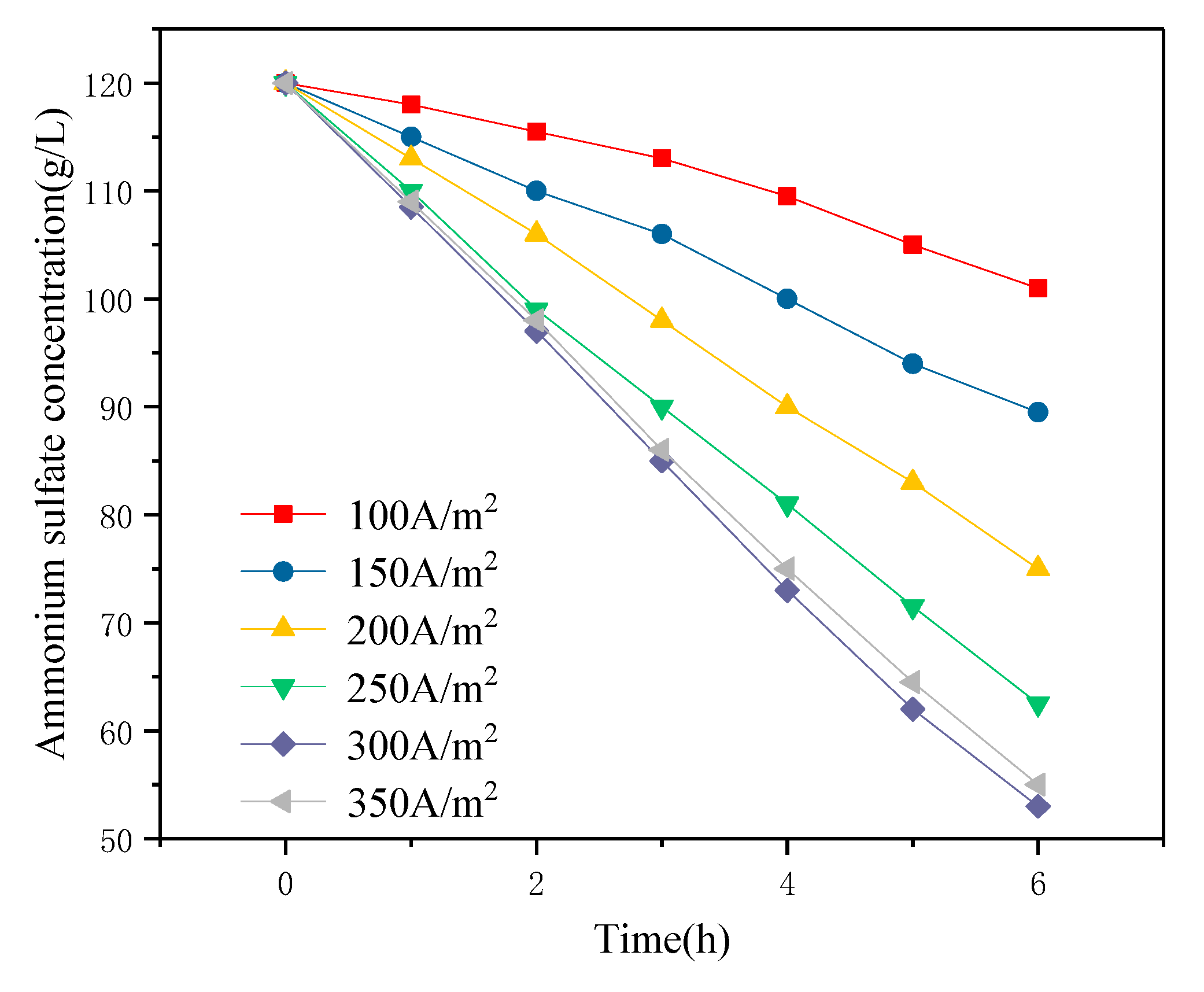
3.4. Effect of Current Density

The effect of different current densities on the decomposition rate of ammonium sulfate in the cathode chamber was studied. Current densities of 100, 150, 200, 250, 300, and 350 A/m2 were selected for continuous electrolysis for 6 h and the changes in ammonium sulfate concentration in the cathode compartment are shown in Figure 5. It was found that with the increase of current density in the range of 100 to 300 A/m2, the driving force was enhanced, the permeation rate of NH4+ and SO42− was accelerated, and the decomposition rate of ammonium sulfate in the cathode chamber was continuously improved. However, the rate of decomposition of ammonium sulfate decreased slightly at a current density of 350 A/m2. The reason may be that the current density was too high, and consequently, the gas rate of the electrode plate was too fast, with the bubbles affecting the ion concentration around the electrode plate. This would reduce the actual working area of the electrode plate. In addition, the decomposition rate of ammonium sulfate was low because the ion-exchange membrane was not adapted for high current densities [25].

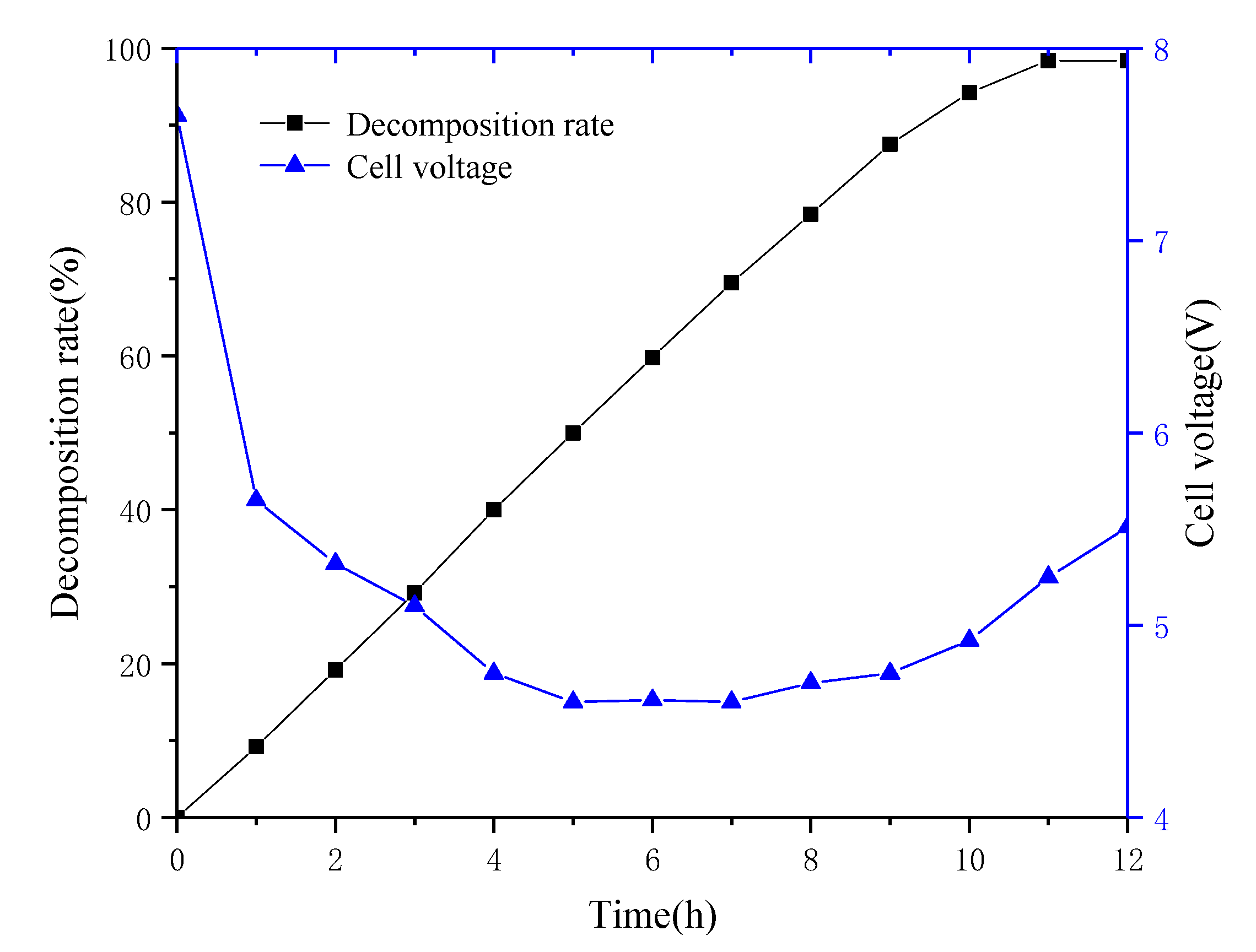
3.5. Effect of Time on Electrolysis

The membrane electrolyzer was operated at a constant current density of 300 A/m2. The effect of electrolysis time on the decomposition rate of ammonium sulfate is shown in Figure 6. The results show that with the increase in reaction time, the decomposition rate of ammonium sulfate increased linearly. When the electrolysis time reached 11 h, the decomposition rate of ammonium sulfate was 98.4%. The decomposition rate stabilized after 11 h, which can be explained by the fact that the liquid underwent concentration-dependent diffusion on both sides of the membrane. In the final stage of electrolysis, the number of ions passing through the membrane into the anode chamber under the influence of the DC electric field was similar to the number of ions diffused into the cathode chamber through concentration diffusion; consequently, the decomposition rate was flat. It was also evident that as the electrolysis time increased, the cell voltage dropped rapidly in the first two hours, then slowly decreased, and then slightly increased in the last four hours of electrolysis. The reason may be that the sulfuric acid concentration in the anode chamber was relatively dilute and the conductivity was relatively poor when electrolysis was started, the pores of the ion-exchange membrane were filled with pure water so the membrane resistance was relatively large, the resistance of the entire system was too large, and/or the cell voltage was relatively high. As the electrolysis reaction progresses, the sulfuric acid concentration increases and the system voltage gradually decreases. After 9 h, the concentration of ammonium sulfate decreased, its decomposition became slower, the resistance of the cathode chamber increased, and the cell voltage slightly increased. The sulfuric acid concentration in the anode chamber changed with time, as shown in Figure 7. The sulfuric acid concentration increased continuously at the beginning of electrolysis, and the growth rate slowed down slightly as the ammonium sulfate concentration in the cathode chamber decreased continuously. The ammonia gas generated by electrolysis in the cathode chamber and the ammonia gas generated by the volatilization of the cathode liquid absorbed by the absorption tower were used to generate ammonia water, and the maximum concentration of ammonia water in the absorption tower can reach 0.39 mol/L.

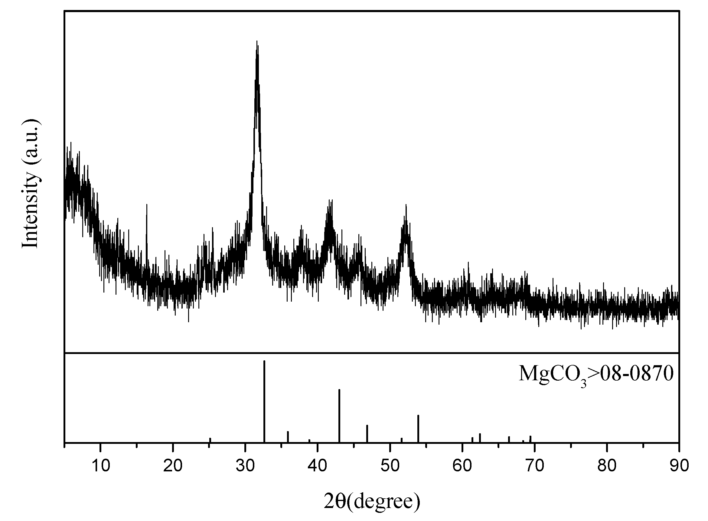
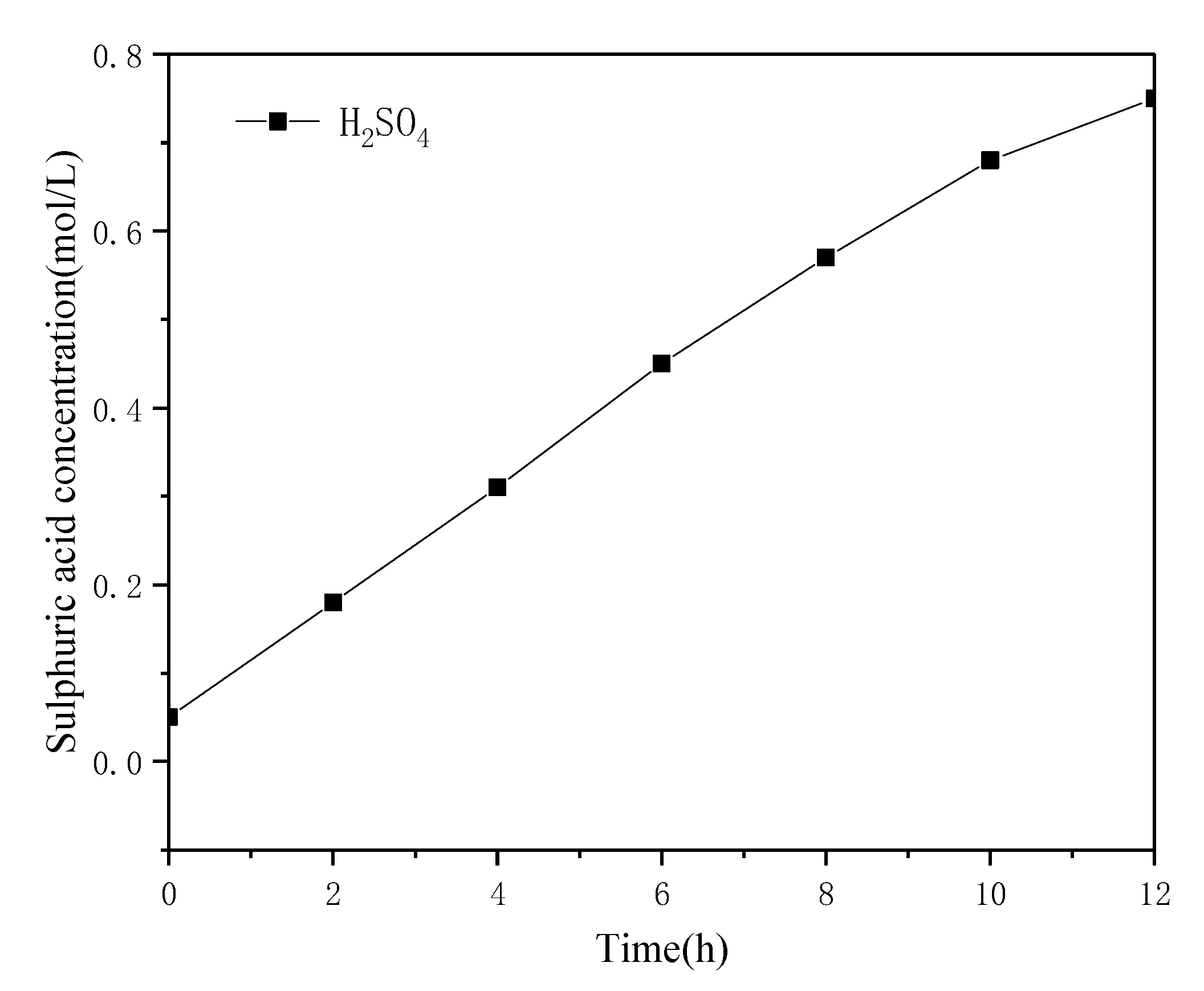
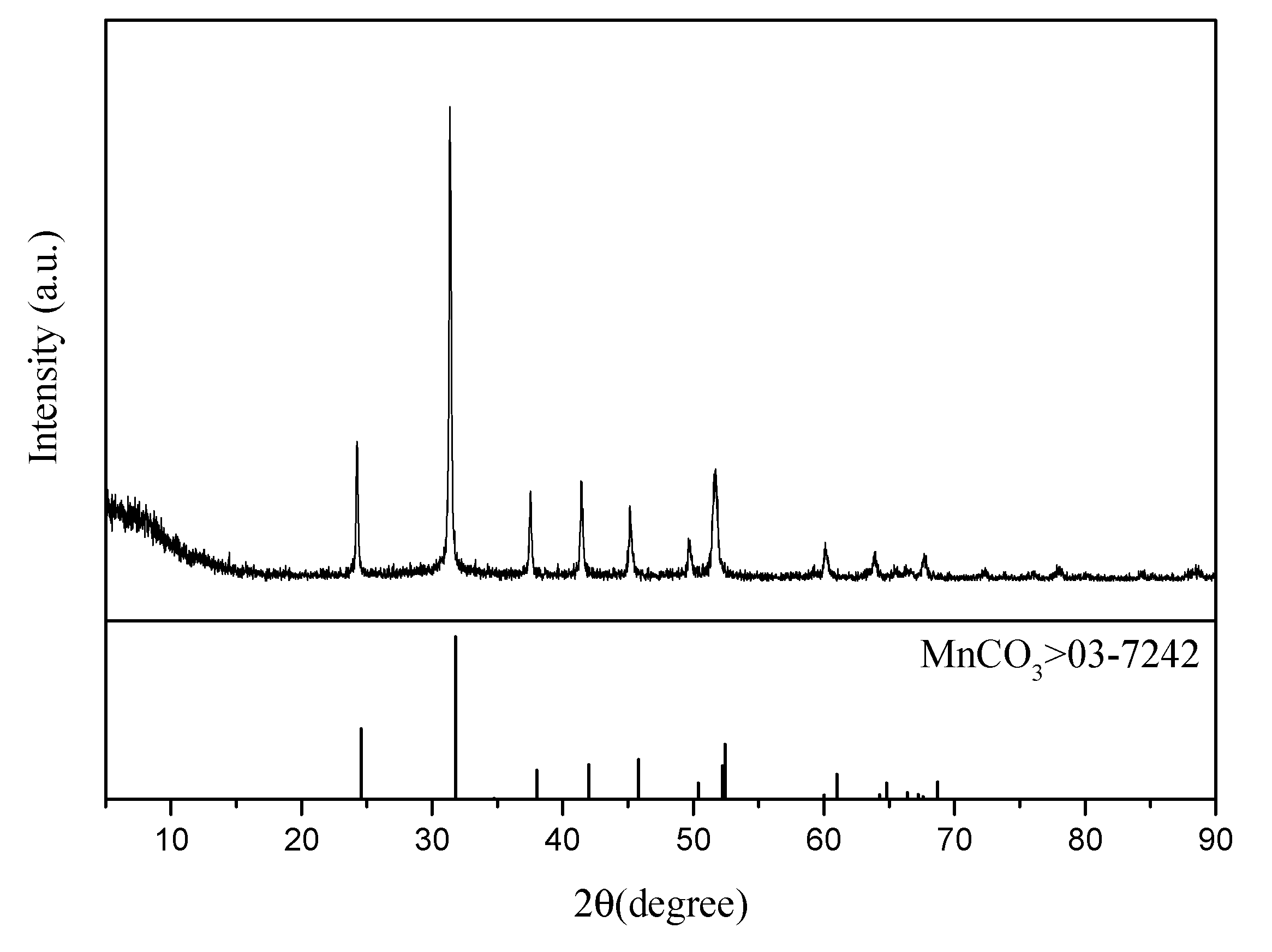
3.6. Analysis and Discussion of Substances Produced by the Removal of Impurities

The ammonium sulfate double salt crystal can be completely dissolved in water, and the impurity removal effect has a great influence on the subsequent electrolysis. In the case when Mn2+ is not completely removed, it enters the cathode chamber through the anode membrane and is discharged on the cathode plate. In this manner, Mn2+ precipitates and adheres to the cathode plate, which decreases the current efficiency of ammonium sulfate decomposition. The cathode plate can be flushed with sulfuric acid to generate manganese sulfate for reuse in electrolytic manganese production. In the case when Mg2+ is not removed completely, Mg2+ reacts with OH generated by the cathode to generate Mg(OH)2 precipitate, which may lead to pipeline blockage. In addition, Mg(OH)2 affects the anion-exchange membrane and increases the membrane resistance. The XRD analysis of the substance obtained by filtration after adding ammonium bicarbonate to the solution, when Mn2+ is removed in the first step, is shown in Figure 8. It was revealed that MnCO3 obtained in this manner is of a high grade and can be directly sold as a commodity. The XRD analysis of the substance obtained after adding ammonium bicarbonate to the solution, except Mg2+ in the second step, is shown in Figure 9. A slight shift in the characteristic peak of MgCO3 was observed, which could be attributed to the crystallization and precipitation of a small amount of ammonium sulfate due to the decrease of solution temperature during filtration, resulting in the change of lattice parameters of MgCO3.

4. Conclusions

The pretreatment-membrane electrolysis method is a new strategy to address the issue of ASDSCs formed during the electrolytic production of manganese. The manganese carbonate produced by pretreatment can be reused in electrolytic manganese production and magnesium carbonate can be made into high temperature resistant materials. The experiments show that the decomposition rate of ammonium sulfate reached 98.4% under the following conditions: the cathode plate uses stainless steel 316 electrodes, a current density of 300 A/m2, T = 40 °C, and a decomposition time of 11 h. The generated sulfuric acid and ammonia water can be recycled for production and the weak solution in the cathode chamber can be used for continuously dissolving ASDSCs. No new waste residue and waste liquid are generated in the treatment process, thus truly realizing green production. In actual production, the electrode plate area can be increased and its spacing can be reduced, the cell voltage can be reduced, and multiple groups of electrolytic cells can be connected in parallel to make full use of the electrode area, to reduce energy consumption, and to gain further economic benefits. The residual impurity of Mg2+ in the filtrate will have a certain influence on the electrolysis process. How to further reduce Mg2+ in the filtrate has great potential for further research.

Author Contributions

Conceptualization, writing—Original draft preparation, data curation, S.Z.; methodology, writing—Review and editing, validation, resources, S.W.; software, formal analysis, Y.Z. and H.D.

Funding

This research was funded by National Natural Science Foundation, grant number 21466019.

Acknowledgments

This project was supported by the National Natural Science Foundation of China (Nos. 21466019).

Conflicts of Interest

The authors declare no conflicts of interest.

References

  1. Xu, F.; Jiang, L.; Dan, Z. Water balance analysis and wastewater recycling investigation in electrolytic manganese industry of China—A case study. Hydrometallurgy 2014, 149, 12–22. [Google Scholar] [CrossRef]
  2. Peng, X.; Yu, H.; Wang, P. Production assessment in the electrolytic manganese metal industry in China. Rev. de Métallurgie-Int. J. Metall. 2011, 108, 437–442. [Google Scholar] [CrossRef]
  3. Zhou, L.X. Review and Prospect of China’s EMM industry for more than 50 years. China’s Manganese Ind. 2010, 28, 1–6. [Google Scholar]
  4. Lu, J.; Dreisinger, D.; Glück, T. Manganese electrodeposition—A literature review. Hydrometallurgy 2014, 141, 105–116. [Google Scholar] [CrossRef]
  5. Jia, T.J.; Zhang, Z.H.; Duan, F.; Song, Z.P.; Liu, N.; Tian, Z.; Zhang, B.; Zhou, J. A treatment Method of Double Salt Crystal in the Process of Electrolytic Manganese. CN108396158A, 14 August 2018. [Google Scholar]
  6. Duan, N.; Dan, Z.G.; Wang, F.; Pan, C.X.; Zhou, C.B.; Jiang, L.H. Electrolytic manganese metal industry experience based China’s new model for cleaner production promotion. Clean. Prod. 2011, 19, 2082–2087. [Google Scholar] [CrossRef]
  7. Wang, Q.A.; Wang, Y.; Liu, B. Analysis and control of ammonia nitrogen pollution in China’s Electrolytic Manganese Industry. Environ. Eng. 2012, 30, 121–123. [Google Scholar]
  8. Tao, C.Y.; Sun, S.; Liu, R.L. Method for Recovering Manganese and Magnesium from Complex Salt Crystals Produced by Electrolytic Manganese Process. CN102154556A, 17 August 2011. [Google Scholar]
  9. He, S.C.; Liu, Z.H.; Liu, Z.Y.; Xia, L.G.; Ma, H.; Zhu, Y. Comprehensive Utilization Method of Electrolytic Manganese Anode Slag and Electrolytic Manganese Crystal Double Salt. CN108842052A, 6 July 2018. [Google Scholar]
  10. Quan, X.J.; Ye, C.Y.; Xiong, Y.Q.; Xiang, J.X. Simultaneous removal of ammonia, P and COD from anaerobically digested piggery wastewater using an integrated process of chemical precipitation and air stripping. Hazard. Mater. 2010, 178, 326–332. [Google Scholar] [CrossRef]
  11. Zhang, X.; Zhu, F.; Chen, L. Removal of ammonia nitrogen from wastewater using an aerobic cathode microbial fuel cell. Bioresour. Technol. 2013, 146, 161–168. [Google Scholar] [CrossRef]
  12. Gendel, Y.; Lahav, O. A novel approach for ammonia removal from fresh-water recirculated aquaculture systems, comprising ion exchange and electrochemical regeneration. Aquac. Eng. 2013, 52, 27–38. [Google Scholar] [CrossRef]
  13. Foliguet, J.M.; Doncoeur, F. Inactivation of virus during pre-chlorination treatment of water at break-point. Water Res. 1974, 8, 651–657. [Google Scholar] [CrossRef]
  14. Zhou, Z.; Hu, L.; Ren, W.C. Effect of humic substances on phosphorus removal by struvite precipitation. Chemosphere 2015, 141, 94–99. [Google Scholar] [CrossRef]
  15. Zhang, Y.Y.; Zhang, W.X.; Pan, B.C. Struvite-based phosphorus recovery from the concentrated bioeffluent by using HFO nanocomposite adsorption: Effect of solution chemistry. Chemosphere 2015, 141, 227–234. [Google Scholar] [CrossRef]
  16. Zhou, J.; Wang, S.F. Electrodeposition of cobalt in double-membrane three-compartment electrolytic reactor. Trans. Nonferr. Metal. Soc. 2016, 26, 1706–1713. [Google Scholar] [CrossRef]
  17. Sata, T. Studies on anion exchange membranes having permselectivity for specificanions in electrodialysis—Effect of hydrophilicity of anion exchange membranes on permselectivity of anions. J. Membr. Sci. 2000, 167, 1–31. [Google Scholar] [CrossRef]
  18. Tanaka, Y. Mass transport and energy consumption in ion-exchange membrane electrodialysis of seawater. J. Membr. Sci. 2003, 215, 265–279. [Google Scholar] [CrossRef]
  19. Grgur, B.N.; Mijin, D.Z. A kinetics study of the methomyl electrochemical degradation in the chloride containing solutions. Appl. Catal. B 2014, 147, 429–438. [Google Scholar] [CrossRef]
  20. Klein, J.M.; Deseure, J.; Bultel, Y. Simulations of heat and mass transfers in tubular solid oxide electrolysis cell. ECS Trans. 2009, 25, 1305–1314. [Google Scholar]
  21. Park, J.S.; Choi, J.H.; Woo, J.J. An electrical impedance spectroscopic(EIS)study on transport characteristics of ion-exchange membrane systems. J. Colloid Interface Sci. 2006, 300, 655–662. [Google Scholar] [CrossRef]
  22. Zhang, W.J.; Ma, J.; Wang, Z.W.; Liu, H.L. Comparisions on test methods of diffusion boundary layer thickness. Membr. Sci. Technol. 2017, 27, 12–18. [Google Scholar]
  23. Cheng, Y.W.; Ding, F.Q.; Fei, Y. Slurry electrolysis of ocean polymetallic nodule. Trans. Nonferrous Met. Soc. China 2010, 20, 60–64. [Google Scholar]
  24. Zhang, W.J.; Ma, J.; Wang, Z.W.; Liu, H.L. Investigations on electrochemical properties in mass transport of ion exchange membrane. Membr. Sci. Technol. 2017, 37, 44–50. [Google Scholar]
  25. Yuan, S.; Kai, X.J.; Ting, A.Z.; Guo, Z.L. Cleaner alumina production from coal fly ash: Membrane electrolysis designed for sulfuric acid leachate. J. Clean. Prod. 2019. [Google Scholar] [CrossRef]
Figure 1. Schematic diagram of ion transport.
Crystals 09 00667 g001
Figure 2. Effect of different cathode materials (current density 200 A/m2, T = 30 °C, 0.05 mol/L H2SO4).
Crystals 09 00667 g002
Figure 3. Influence of temperature on the rate of ammonium sulfate decomposition (current density 200 A/m2, 0.05 mol/L H2SO4).
Crystals 09 00667 g003
Figure 4. Effect of initial acid concentration in the anode chamber on the decomposition rate of ammonium sulfate (current density 200A/m2, T = 30 °C).
Crystals 09 00667 g004
Figure 5. Effect of current density on the decomposition rate of ammonium sulfate (T = 30 °C, 0.05 mol/L H2SO4).
Crystals 09 00667 g005
Figure 6. Decomposition rate and cell voltage versus time (current density 300 A/m2, T = 30 °C, 0.05 mol/L H2SO4).
Crystals 09 00667 g006
Figure 7. Variations in the acid concentration in the anode chamber over time (current density 300 A/m2, T = 30 °C, 0.05 mol/L H2SO4).
Crystals 09 00667 g007
Figure 8. XRD analysis of the first filtered product.
Crystals 09 00667 g008
Figure 9. XRD analysis of the second filtered product.
Crystals 09 00667 g009
Table 1. ICP analysis of ammonium sulfate double salt crystals (ASDSCs).
Sampling LocationZn (%)Fe (%)Mg (%)Ca (%)Mn (g/L)(NH4)2SO4 (g/L)
Transfer tank
High pool
Neutral liquid pool
0.019
0.017
0.019
0.084
0.064
0.091
6.65
6.74
6.76
0.061
0.047
0.071
5.54
6.12
2.60
36.12
36.97
38.92
Neutral flow cell0.0210.0746.530.0563.0836.18
Table 2. Indicators of the experimental membranes [16].
Membrane Type Function GroupExchange Capacity/
(mmol·g−1)
Resistance/
(Ω·cm2)
Permselectivity/%Strength/kPaThickness/μm
AMVRN (CH3)3Cl2.02.5>96200120

