1. Introduction
It is well known that liquid crystal (LC) made a truly interdisciplinary impact on modern technology from the 1970s to today, because the refractive index of liquid crystal can be tuned by external perturbations, such as temperature, electric field, and magnetic field. We can find its application in lasers, diffraction gratings, spatial light modulators, dynamic lenses, flat panel displays, etc. Among those applications, the evolution of flat-panel displays is driven by developing the new switching modes of the liquid crystals. In order to get better display performance, researchers have tried to explore the liquid-crystal phase with chirality. Recent studies have focused on an intrinsic optical-isotropic phase in liquid crystal materials blue phases (BPs) [
1,
2,
3,
4,
5,
6,
7,
8]. When the BP cell is inserted between two crossed polarizers, a perfect dark state is detected and, theoretically, the BP cell exhibits an unlimited contrast ratio for display when the BP reflection wavelength is less than the visible light. The optical property of the BPs can be switched from optical isotropy to anisotropy when we apply a voltage on them. The direction of the field-induced optical axis is determined by the physical parameters of the LC and the direction of the applied field, and the field-dependence induced birefringence is explained by the Kerr effect [
1,
2].
BPs usually appear in a narrow temperature range just below the isotropic liquid phase. When the LC are cooled from liquid phase, the LC molecules are formed into double-twist cylinders (DTCs), and then these DTCs stack in the space. According to the ways to stack the DTCs, we can find three BPs at different temperatures. The two lowest temperature BPs are BPI and BPII, and they exhibit cubic crystal structures. The highest temperature mesophase is BPIII, which is the focus of this paper. A large-scale computer simulation and the experimental results of BPIII provide strong evidence that BPIII should be formed by an amorphous network of the disclination and the randomly-distributing DTCs, and they also show that an electric field can order the directions of the DTCs in amorphous BPIII [
8,
9]. Compared to the electro-optical properties of BPI and BPII, BPIII exhibits a fast response with no residual birefringence, and there is no hysteresis effect when an in-plane electric field is applied [
10,
11]. Moreover, a transflective device without an internal reflector using a room-temperature BPIII material is demonstrated [
12].
In our previous study, we found that the electro-optical property of BPIII in the high applied voltage was unusual and cannot be simply explained by the extended Kerr effect only [
11,
13]. The extended Kerr effect demonstrates an exponential convergence model to explain the non-linear dependence of effective birefringence on the square of the electric field in the IPS-BPI cell and it discusses the high-order electro-optical effect [
13]. Experimentally, they saw that when the induced birefringence of their sample saturates, the transmittance became saturated in the high voltage region [
13]. However, for the IPS-BPIII cell reported in our previous study, the transmittance still increased, and even the induced birefringence became saturated [
11]. It means that the extended Kerr effect cannot fit the electro-optical behavior of the IPS-BPIII cell in the high voltage region. It is because the extended Kerr effect reported in [
13] focused on the centrosymmetric crystal, such as BPI or BPII, not focused on BPIII with amorphous structure. Thus, in their model of the extended Kerr effect, the odd-order terms of the electro-optical effects, such as the Pockels effect, were neglected. The other interesting experimental result in our previous paper [
12] pointed that the transmittance was usually stronger near the boundary of the electrode and was lower in the middle of two neighboring strip electrodes. The non-uniform transmittance distribution starting from one electrode boundary to the other can be improved by increasing the cell thickness of the IPS-BPIII cell [
12]. In the IPS cell, the favored electric-field direction is unanimous on the substrate, and then the distribution of the electric field between two neighboring strip electrodes is assumed to be uniform above a reasonable thickness. Therefore, most studies neglected the influence of the complex electric-field distribution at the edge of the electrode strip. By simulating the electric-field distribution of the IPS cell, the directions of the electric field at the edge of the strip electrode splay along the normal direction of the substrate. As we know, the optical properties of the BPIII induced by the field distortion depend not only on the strength of the electric field but also on the direction of the electric field [
9,
11,
14]. Thus, at the edge of the electrodes in the IPS-BPIII cell there seems to be an inherent effect. If we would like to enhance or magnify the inherent phenomenon, we should create an electric field that is not perpendicular or parallel to the normal direction of the substrate between two neighboring electrodes.
In this paper, we use a tilted-field-switching (TFS) cell, where the directions of the electric fields are tilted with respect to the normal direction of the substrate, to drive the BPIII LC. The electro-optical properties of the IPS-BPIII and the TFS-BPIII cells are compared here. The experimental results show that when the cell gap is thinner, transmittance is higher in the TFS-BPIII cell, but it is lower in the IPS-BPIII cell. The difference is from the spatial distributions of the electric field in these two cells. By measuring the induced birefringence with varying strength of the electric field in the TFS-BPIII cell, the Kerr effect occurs in the low electric field and the Pockels effect dominates in the high electric field. The transmittances of the TFS-BPIII cell depend on the polarity of the applied field from the low frequency to 10 kHz. For a constant frequency of the applied voltage, the transmittances in the positive and negative polarities of the applied fields are not equal from 40 to 200 V. This is evidence of the flexoelectric effect in the TFS-BPIII cell. Moreover, the transmittance symmetric-broken behavior indicates that in the low applied voltage the influence of the flexoelectric effect cannot be ignored. By using the asymmetric intensity, seen in the TFS-BPIII cell, the TFS-BPIII cell can switch the transmitting intensity just by reversing the polarity of the applied field.
Flexoelectric coupling in the chiral nematic LC phase has provoked much interest in recent years [
15,
16,
17]. In the flexoelectric-optic effect, the optical axis of the chiral nematic LC is rotated by the electric field perpendicular to it. The features, coupled with microsecond response times, render the switching effect potentially viable for future use in electro-optical devices and display applications [
18,
19]. The effect of flexoelectric coupling on the cubic BPs (BPI and BPII) has been the subject of extensive theoretical investigations [
20,
21], and the contribution of the flexoelectricity to the Pockels effect in mechanically distorted cubic BPs has been experimentally and theoretically discussed [
22,
23]. However, no paper reports the Pockels effect in the amorphous BPIII. Here, we provide the interesting experimental data relating to these two effects in our TFS-BPIII cell.
3. Results
We know that the optical anisotropy of BPs can be induced by applying an external electric field [
1]. In order to observe that phenomenon, the direction of the electric field applied on the BPs and the direction of the incident light must not be parallel [
1,
5,
7,
8]. Here, we filled our BPIII material into the convention IPS cells and the TFS cells with different cell gaps, which are 10, 30, and 50 μm. For the IPS cells, the electrode width and the electrode space are the same as the TFS cell mentioned in
Section 2. Through the microscopic observations in
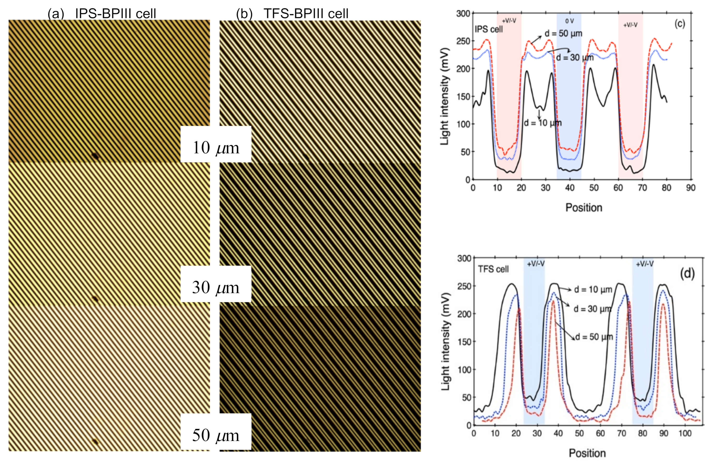
Figure 2a,b, they seem no different. We analyzed the intensity distributions of the IPS- and TFS-BPIII cells from these microscopic pictures, and found a contrary dependence of the light intensity and cell gap in the IPS- and TFS-BPIII cells, as shown in
Figure 2c,d. In the IPS-BPIII cell, the distribution of the light intensity is more uniform as the cell gap increases; thus, the light intensity is stronger in the thick-cell-gap IPS-BPIII cell. However, in the TFS-BPIII cell, we saw a contrary dependence of the light intensity and cell gap, as shown in
Figure 2b,d. The transmitting intensity reduces as the cell gap increases in the TFS-BPIII cell, and the TFS-BPIII cell also exhibits the different intensity distribution as we saw in the IPS-BPIII cell in
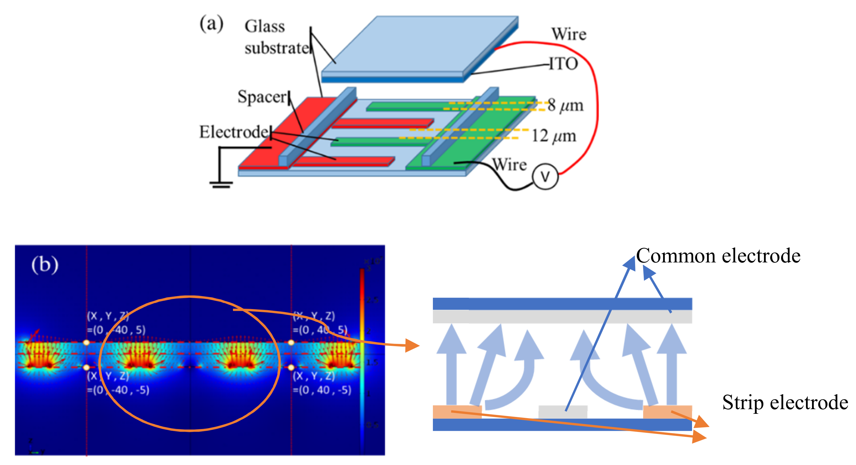
Figure 2a,c. The highest intensity appears between the neighborhood strips of the comb-like electrode in the TFS-BPIII cell in
Figure 2b,d. Referring to the distribution of the electric field of the TFS-cell in
Figure 1b, the directions of the electric field above the strip electrode are perpendicular to the substrate, and then tilt down to the substrate when the electric field goes away from the strip electrode along the substrate plane. This means that the effective horizontal electric field varies not only along the normal direction but also along the plane of the substrate. In the middle of the two neighboring strip electrodes, a null electric field occurs in
Figure 1b. It may affect the electro-optical response of the BPIII and in addition may induce other phenomena due to the non-uniform spatial distribution of the electric field in three dimensions.
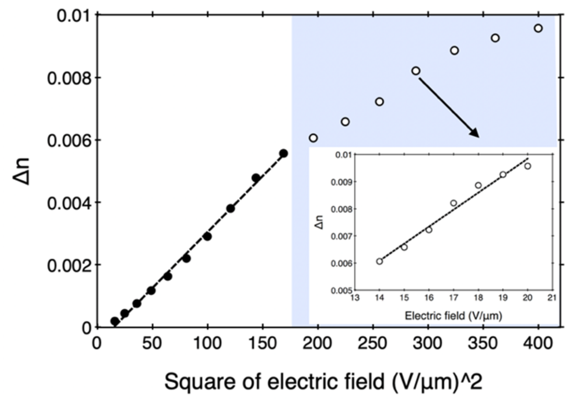
A linear polarized light with 455-nm wavelength was used to be a probe beam to determine the induced birefringence of the TFS-BPIII cell. The phase difference of the probe beam after passing the TFS-BPIII cell was collected by the polarimeter (PAX1000VIS, Thorlabs, NJ, USA), and it was used to estimate the amount of the induced birefringence. The induced birefringence of the 10-μm TFS-BPIII cell at the different applied voltages is shown in
Figure 3. In
Figure 3, the induced birefringence exhibits square dependence of the applied field in the lower applied voltage regime (< 140 V); this is already explained by the Kerr effect [
11]. The Kerr constant
K can be calculated by ∆
n =
λKE2 and is 0.08 nm/V
2. However, when the applied voltage is larger than 140 V, it transfers to a linear electro-optic effect (i.e., the Pockels effect).
In liquid crystals, when an external electric field is applied, there are two main mechanisms suggested: convention dielectric coupling and flexoelectric coupling. Among them, the conventional dielectric coupling cannot produce the linear electro-optic effect, in that the free density is proportional to
and moreover the effect is independent of the polarity of the electric field [
20]. However, the flexoelectric coupling, described by a term in the free energy that is
, can produce the linear electro-optic effect and it induces optical-axis reorientation effect that depends on the field polarity [
16,
17,
19]. This phenomenon of the optical-axis reorientation depending on the field polarity was observed in our TFS-BPIII cell as shown in
Figure 4 and in the
Video S1. (
Supplementary Materials).
A possibility of polar flexoelectric electro-optical switching in the cubic BPs was considered theoretically by Kitzerow [
1]. When the electric field is applied along the axis of a DTC, it will distort the director, but this distortion will not affect the birefringence. However, when the electric field is applied perpendicular to the axis of a DTC, it will modify its birefringence. For an undistorted BP, the modification on birefringence may be cancelled by another DTC, which is also perpendicular to the electric field [
1]. Kitzerow’s argument explains that flexoelectric coupling in the IPS-cubic-BP cell is not obvious, and it cannot even be seen when the distribution of the electric field is uniform. For BPIII, because the orientation of the DTCs are random, it reduces the probability of cancelling the birefringence, induced by flexoelectric coupling. At the edge of the strip electrode in the IPS-BPIII cell, the direction of the electric field splays, and change in the birefringence due to the flexoelectric coupling of DTCs may not be cancelled out by other DTCs, as shown in
Figure 2 (and also
Video S2). Therefore, we can say that the flexoelectric coupling at the edge of the strip electrode and the dielectric coupling in the middle area between two neighboring electrodes contribute to induce the Kerr effect in the IPS-BPIII cell. By reducing the frequency of the applied field, in the thinner cell, the dynamic brightness switching at the edge of the strip electrode can be observed as reversing the polarity of the applied field in the IPS-BPIII cell, due to the flexoelectric effect, as shown in
Video S2. Now, for the TFS-BPIII cell, because the direction of the electric field tilted from the normal direction of the substrate, the spatial distribution of the electric field is not uniform everywhere, as seen in
Figure 1. The flexoelectricity induced electro-optical effect in the TFS-BPIII cell becomes easier to observe by introducing the low-frequency electric field, as shown in
Figure 5. By increasing the cell gap in TFS-BPIII cell, the tilted angle of the electric field is reduced via simulation, and it suppresses the contribution of the flexoelectricity.
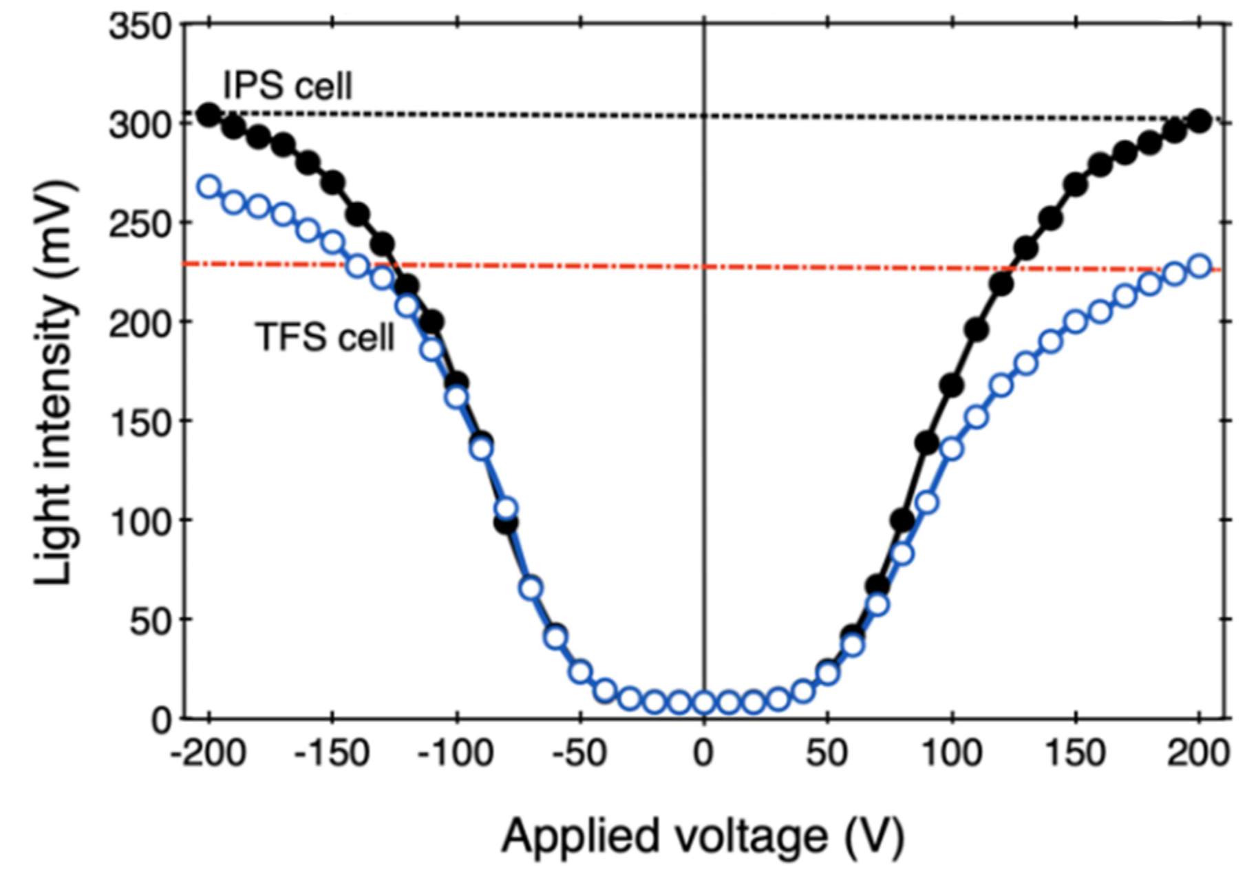
The transmitting intensities in positive and negative polarities of the electric field are not equal and show an asymmetric curve with respect to the null field in
Figure 5. The intensity-asymmetric behavior occurs after the TFS-BPIII cell is driven, and the difference of the transmitting intensities is expended as the applied voltage increases. However, the transmittance symmetric-broken behavior is not significant in the IPS-BPIII cell in
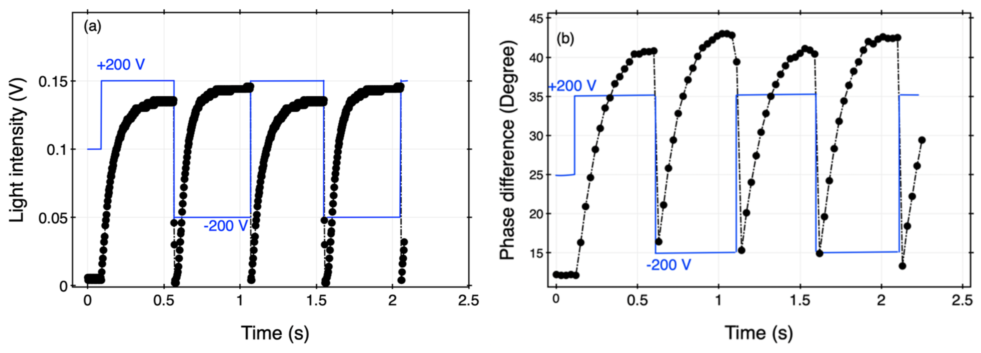
Figure 5. The reason for the difference of the light intensities with fields of the positive and negative polarities in TFS-BPIII cell can be discussed by referring the experimental results of the time-variation phase difference in
Figure 4b. The phase difference in
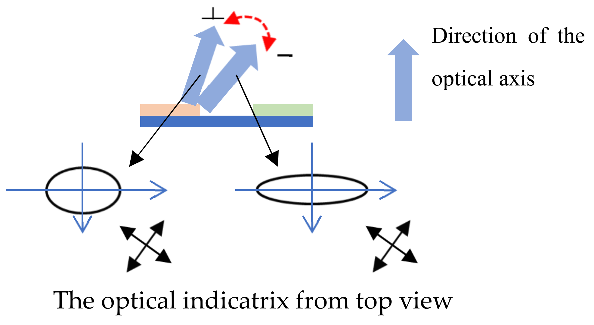
Figure 4b is measured directly by the polarimeter and it shows that in the field of the negative polarity the phase difference (i.e., the effective field-induced birefringence) is slightly higher than that in the positive polarity. For an observer, the phase difference is caused by the orientation of the optical axis (i.e., the tilted angle of the optical axis). In the flexoelectric-optic effect, the optical axis is rotated by the electric field perpendicular to it, thus according to the field distribution of the TFS-BPIII cell in
Figure 1b, the optical axis changes its orientation along the normal direction of the substrate, as shown in
Figure 6. In the negative polarity field, the orientation of the optical axis is more parallel to the substrate and then the normal incident light can feel a larger phase difference.
The experimental results in
Figure 3,
Figure 4,
Figure 5 and
Figure 6 confirm the flexoelectricity as a mechanism for the Pockels effect in the high applied voltage in the TFS-BPIII cell. Referring to a model of the Pockels effect of BPs introduced by Castle in [
21], the difference of the splay and bend flexoelectric coefficients,
e =
e1 −
e3, can be roughly estimated from slope of
Figure 3 when the Pockels effect occurs through [
22],
, where
no is the ordinary refractive index. The non-zero
rBP appears only in the mechanically distorted state, for which Δ
n is not zero and
where
a is the length of the unit cell, relating to the pitch of the cubic BPs,
n is the average refractive index, and
K is elastic coefficients. As BPIII is amorphous, the
a can be replaced by the diameter of the DTCs. The diameter of the DTC can be estimated from the pitch of the BPIII, which is obtained from the reflection spectrum (
P =
λ/
n). The reflection wavelength of the BPIII is usually shorter than 450 nm and the average refractive index of LC is 1.6, thus we can estimate the pitch, which is shorter than 282 nm [
10]. However, the diameter of the DTC is a quarter of the pitch and is about 70 nm. Thus, the nearest dimension of
a is 100 nm. By combining the equations above and inserting the related parameters, we find
e/K∼ 0.052 C/Nm. Compared to the typical value
e of nematic LC or chiral nematic LC [
18,
24], this calculated value is reasonable.
The reason that we do not see the Pockels effect in the IPS-BPIII cell can be discussed from the distribution of the electric field. According to the simulated distribution of the electric field of the 10-μm IPS cell in
Video S2, the distribution of the electric field at the edge of the strip electrode splays and then it can induce the flexoelectric effect at the edge of the strip electrode.
Video S2 shows that as reversing the polarity of the external field, in the IPS-BPPIII cell, the slight change in light intensity caused by flexoelectric effect occurs in the edge of the strip electrode. We can say that the transmittance caused by the Pockels effect may exist in the IPS-BPIII cell, but is weak, compared to the transmittance caused by the Kerr effect. Thus, the Pockels effect at the edge of the electrode is hidden by the Kerr effect in the middle area.
The electro-optical rise time of the LC is usually defined by the time duration between 10% and 90% transmittance. However, in the TFS- and IPS-BPIII sample shown here, when we reverse the polarity of the AC electric field (i.e., direction of the electric field), the changes in the light intensity are obvious due to the flexoelectric coupling, as shown in
Figure 4 and
Figure S1. This makes it hard to define the rise times and to compare them in the different cell structures under the application of the AC field. In order to prevent the influence of the flexoelectric effect, the rise times and decay times mentioned here were measured when the applied DC field was turned on and off for 5 ms, respectively. According to results of the rise and decay times in the TFS-BPIII cell for different applied voltages, after 140 V (Pockels effect), the rise time decreases from 1 to 0.5 ms; but the decay time (~0.5 ms) is no different for in each applied voltage. Under the same experimental condition, the average rise time detected in the IPS-BPIII cell is 1.5 ms, which is almost double times in the TFS-BPIII cell. By using the asymmetric intensity, seen in the TFS-BPIII cell, the TFS-BPIII cell can switch the transmitting intensity just by reversing the polarity of the applied field, such as in
Figure 6.
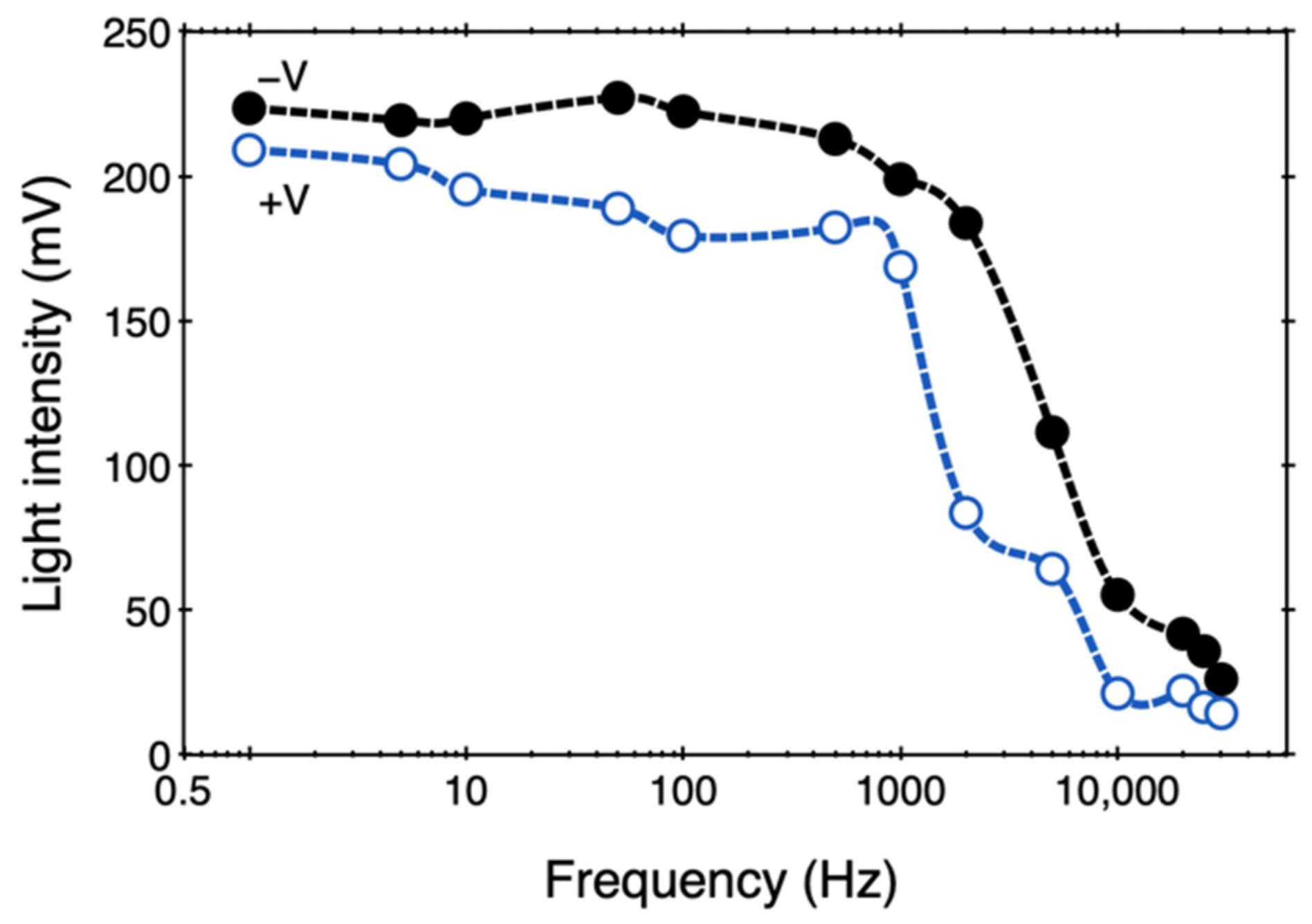
Figure 7 displays the difference of the transmitting intensities in two opposite polarities of the electric field at various frequencies. The transmitting intensities decrease with increase in the frequency of the electric field and the transmittance difference between the polarities becomes less in the high frequency of the electric field. The transmittance decreases dramatically as the frequency increases over 2 kHz. This has been discussed by the effect of the dielectric dispersion [
25].


