Article

Magneto-Optical Isolator Based on Ultra-Wideband Photonic Crystals Waveguide for 5G Communication System

1
Shenzhen Key Laboratory of Micro-Nano Photonic Information Technology, College of Physics and Optoelectronic Engineering, Shenzhen 518060, Guangdong, China
2
College of Electronics and Information Technology, Shenzhen University, Shenzhen 518060, Guangdong, China
*
Authors to whom correspondence should be addressed.
These authors contribute equally to this work.
Crystals 2019, 9(11), 570; https://doi.org/10.3390/cryst9110570
Submission received: 25 September 2019 / Revised: 27 October 2019 / Accepted: 28 October 2019 / Published: 30 October 2019
(This article belongs to the Special Issue Sonic and Photonic Crystals)

Abstract

:
This paper presents a novel magneto-optical isolator based on an ultra-wideband and high efficiency photonic crystals (PCs) waveguide and gyromagnetic ferrites. The three-dimensional numerical simulation finds that the photonic crystals waveguide’s (PCW) transmission efficiency rises with its height and width. The corresponding experiments are performed by using a triangular lattice Al2O3 dielectric posts array in 5G millimeter wave band. The measured transmission efficiency is up to 90.78% for the optimal PCs waveguide structure, which has ultra-wide operating bandwidth from 23.45 to 31.25 GHz. The magneto-optical isolator is designed by inserting two rectangular gyromagnetic ferrites into the PCs waveguide. Due to the contrast between the effective permeability of the left and right circular polarization waves passing through the magnetized ferrite sheets, the ferromagnetic resonance absorption of the forward and reverse waves is different. By using finite element method, the isolation is optimized to be 49.49 dB for the isolator and its relative bandwidth reaches 8.85%. The high isolation, broadband, and easy integration indicate that our designed magneto-optical isolator has significant advantage in 5G communication systems.

1. Introduction

Photonic crystals (PCs) can control the motion of photons because of their unique properties, such as photonic band-gap (PBG) and optical localization [1,2]. PCs are considered to be the core of integrated optical communication in the future. PCs with PBG have many direct applications like mirror [3,4], grating [5], and filters [6]. Based on optical localization, PCs with point or line defects have been extensively researched as the basis of high-quality resonator cavities [7,8] and photonic crystals waveguide (PCW) [9,10].
Due to the emergence of PCW as a new transmission line, photonic integrated devices with PCW, such as circulators [11,12,13], optical distributors [14,15], logical gates [16], all-optical adders [17], optical isolators [18,19], encoders [20], and so on, are studied extensively. However, with the rapid development of photonic crystal integrated devices, more attention shall be paid to the problem of increased bit error rate because of nonlinear effect in large scale integrated optical path. Optical isolators have also been developed from the original one-dimensional photonic crystal isolator [18] to two-dimensional photonic crystal isolator [19], which can effectively isolate noise or reflections in the integrated optical path to reduce the bit error rate. Low-power transmission of the PCW can be used to avoid the occurrence of nonlinear effects in all-optical 8-to-3 encoder [20]. As we know, the 5G communication system is planned around 24 ~ 28 GHz by most nations and areas, which has broadband characteristic. Therefore, the research of broadband isolator based on low loss PCW has great significance to reduce the bit error rate and nonlinear effect of the communication system. In our previous work [21], based on Faraday rotation effect, a four-ports double Y-shaped magneto-photonic crystal circulator was designed by using an ultra-wideband PCW for 5G communication system.
In this work, we focused on designing a broadband magneto-optical (MO) isolator by using the PCW and gyromagnetic materials, which is based on ferromagnetic resonance absorption effect. The MO isolator was formed by inserting two rectangular gyromagnetic ferrites into an ultra-wideband and high efficiency PCW that consisted of triangular lattice Al2O3 dielectric posts. Based on the three-dimensional (3D) numerical simulation, it was found that the transmission efficiency of the PCW rises with its height and width. The optimal PCW structure with high transmission efficiency of 90.78% and relative bandwidth of 28.71% was achieved by numerical simulation and experimental verification, which was be used to design the MO isolator in 5G millimeter waveband here. By investigating the influence of the ferrite sheets’ size and position in the PCW on the performance of the isolator, the structural and performance parameters of the MO isolator were optimized. The isolation of the MO isolator was optimized to be 49.49 dB at 26.30 GHz by finite element method (FEM) and kept above 15 dB between 24.85 to 27.15 GHz (the relative bandwidth is 8.85%) with the best ferrite sheets’ length L of 20 mm and position d of 1 mm. The MO isolator also had an excellent forward transmission characteristic that the transmission efficiency kept above −3 dB in a wide frequency range from 22.00 to 27.40 GHz. The numerical results show that the MO isolator with broadband and high isolation can operate in the 24.85 to 27.15 GHz. If the photonic crystal devices are used to integrate 5G communication systems in the future, our design scheme will have potential application value.

2. Materials and Methods

2.1. Design of MO Isolator

As shown in Figure 1, our MO isolator (Shenzhen University, Shenzhen, Guangdong, China) was formed by inserting two rectangular gyromagnetic ferrite sheets (red) into an ultra-wideband and high efficiency PCW (white). The PCW includes two triangle lattice photonic crystals (TLPCs) formed by Al2O3 dielectric post arrays. The dielectric post arrays fixed with high accuracy by the upper (transparent) and under (blue) aluminous panels in order to guarantee the TLPCs’ PBG characteristic. The two ferrite sheets are clung onto the inside of the upper and under panels, respectively, which keep a distance of d from the boundary of the PCW. Four flange interfaces were designed at each side of the PCW to connect with the testing device.

2.2. Ultra-Wideband PCW with PBG

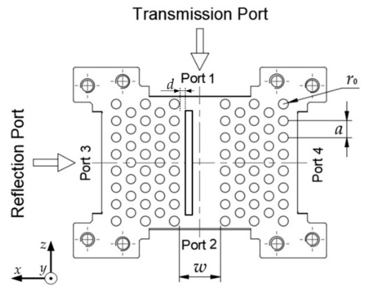
In theory, the PCs’ PBG characteristic decides the spectrum of the signal which can be propagated in the PCW. The section view of the MO isolator is shown in Figure 2, in which the TLPCs’ lattice constant a is 3.5 mm. The Al2O3 posts’ dielectric constant and radius r0 are 9.2 and 1 mm, respectively. The width of the PCW is marked by w, which is the distance of the two TLPCs. The four ports marked Port 1, 2, 3, 4, respectively, are transmission ports and reflection ports.
The PBG of the TLPCs is calculated to be 22.89 to 31.20 GHz like that in [21] and not repeated here. Theoretically, a signal within that frequency range can propagate stably in the PCW. In our previous work [21], the transmission efficiency of the PCW rose when its width changed from 6.25 to 10.70 mm in the three-dimensional numerical simulation. The optimal PCW structure of 8.64 × 4.32 mm2 was chosen to investigate its transmission characteristics.
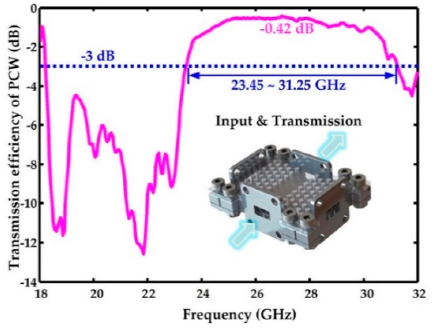
The transmission efficiency’s variation of the PCW with frequency is calculated by FEM, and the numerical results show that there is an ultra-wide bandwidth of the PCW from 21.60 to 31.90 GHz, in which the transmission efficiency keeps above −3 dB (about 50%). In order to validate the aforementioned numerical results, the experiments were performed at the 5G millimeter wave band. The experimental verification of the PCW is described in detail in [21] and not repeated here. The variation of the PCW’s transmission efficiency with frequency is shown in Figure 3, which has subtracted the loss of the cables and connectors.
In the experiments, the peak of transmission efficiency could reach 90.78% (−0.42 dB) and the operating bandwidth of the PCW was about 7.8 GHz. The transmission efficiency kept above −3 dB between 23.45 to 31.25 GHz, while the relative bandwidth was about 28.71%. This experiment not only verifies the high transmission efficiency and ultra-wideband characteristics of PCW but also provides a basis for developing a novel MO isolator.

3. MO Isolator

3.1. Theoretical Model of MO Isolator

The transmission characteristics of the MO isolator were based on a Maxwell equation with permeability tensor [μr] like [21]:
ε 1 · × ( [ μ r ] 1 · × E ) = ω 2 / c 2 · E .
In millimeter wave band, the gyromagnetic characteristic of ferrite magnetized by external DC magnetic field H0 can be expressed as tensor permeability [μr], like [21]. The elements of tensor permeability using Hilbert type are expressed as follows:
μ r = 1 + ω m ( ω 0 + i α ω ) / [ ( ω 0 + i α ω ) 2 ω 2 ] ,
κ = ω m ω / [ ( ω 0 + i α ω ) 2 ω 2 ] ,
ω 0 = μ 0 γ H 0 ,
ω m = μ 0 γ M s ,
where the loss coefficient α of NiZn Ferrite (εr = 13.5) is generally chosen to be 0.05. The gyromagnetic ratio γ = 1.759 × 10¹¹ C/kg, while saturation magnetization Ms = 2.39 × 10⁵ A/m.
Our MO isolator adopted a similar design to that of H-plane rectangular waveguide resonance isolator, as shown in Figure 4a. A resonance isolator works on the utilization of the fact that at certain regions x = x1 and x = bx1 in the waveguide’s cross section, and the magnetic vector is circularly polarized with one sense of rotation for wave propagation in the forward direction and an opposite sense of rotation for the reverse propagation. In the E-plane resonance isolator, the gyromagnetic phenomena in ferrite is also understood in terms of the circularly polarized components of the magnetic field [22].
In microwave engineering, the effective permeability of right or left circular polarization waves in the magnetized NiZn ferrite sheets is expressed as follows:
μ ± = μ r κ = 1 + ω m ω 0 + i α ω ω .
When the loss of ferrite is considered in Equations (2) and (3), the effective permeability μ± of right or left circular polarized magnetic field has an imaginary part that represents the loss in Equation (6). The variations of the real part μ± and the imaginary part μ± of the effective permeability with ω/ω0 are, respectively, shown in Figure 4b,c. The effective permeability of the right or left circular polarization waves passing through the magnetized ferrite is introduced in detail in reference [23].
The resonance isolator can work at the resonance condition ω = ω0 under a biasing field H0. This results in the near-resonance absorption of the backward traveling waves due to a fairly large imaginary part of the effective permeability observed by those waves. The forward waves, observing a quite small imaginary part of the effective permeability, experience a relatively low loss propagation, resulting therefore in the one-way transmission function of the isolator. Some typical configurations of the resonance isolator were introduced in detail in [23].
Similarly, the MO isolator in Figure 1 is designed according to the feature of the H-plane rectangular waveguide resonance isolator. We assume that the field vectors of the TE10 mode satisfy the condition of Hx/Hz = ±j when the ferrite sheets are placed at the same position x = x1 like [23]. The TE10 mode launched from Port 2 in Figure 2 is a right circular polarization wave for the direction of H0. Because the effective permeability μ+ of the right circular polarization wave has a large imaginary part of μ+, this results in obvious ferromagnetic resonance absorption of the traveling wave. However, the forward wave launched from Port 1 in Figure 2 is a left circular polarization wave for the direction of H0. Because the effective permeability μ of the left circular polarization wave has a small imaginary part of μ, the energy of the electromagnetic wave is attenuated so little that it can be propagated to the output Port 2.

3.2. Numerical Results

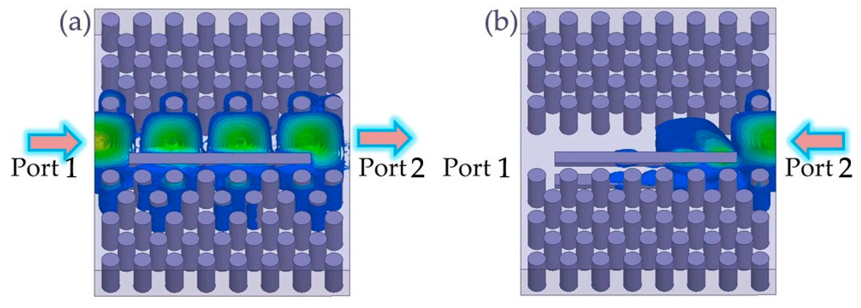
When external magnetic field H0 = 7.4 × 10⁵ A/m is applied on the two rectangular ferrite sheets, with length, width, and thickness of L = 20 mm, M = 1.5 mm, and N = 0.5 mm, respectively, the function of the MO isolator is calculated by FEM, as shown in Figure 5. The electromagnetic field propagations are simulated at the central frequency of 26 GHz with scattering boundary condition (SBC).
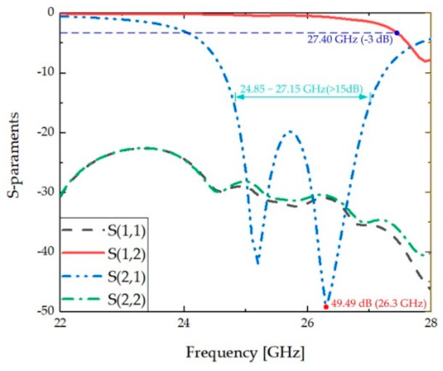
As shown in Figure 5a, a signal launched from the input port (Port 1) is transmitted stably to the transmission port (Port 2). Irreversibly, when a signal is launched form Port 2, the power of the signal is lost by the ferromagnetic resonance, and Port 1 is isolated, as shown in Figure 5b. The MO isolator’s function of one-way transmission and reverse isolation are perfectly implemented. In Figure 6, the transmission characteristics of the MO isolator are also numerically investigated within the frequency range from 22 to 28 GHz, which is totally included in the PBG mentioned above.
The numerical results show that the isolation of the MO isolator is optimized to be 49.49 dB at 26.30 GHz by finite element method (FEM) and keeps above 15 dB between 24.85 to 27.15 GHz (the relative bandwidth is about 8.85%). The MO isolator also has an excellent forward transmission characteristic that the transmission efficiency keeps above −3 dB in a wide frequency range from 22.00 to 27.40 GHz. The reflections (S11, S22) of the two ports are both little, which keep below −20 dB in the whole frequency range, as shown in Figure 6.

3.3. Disscusion

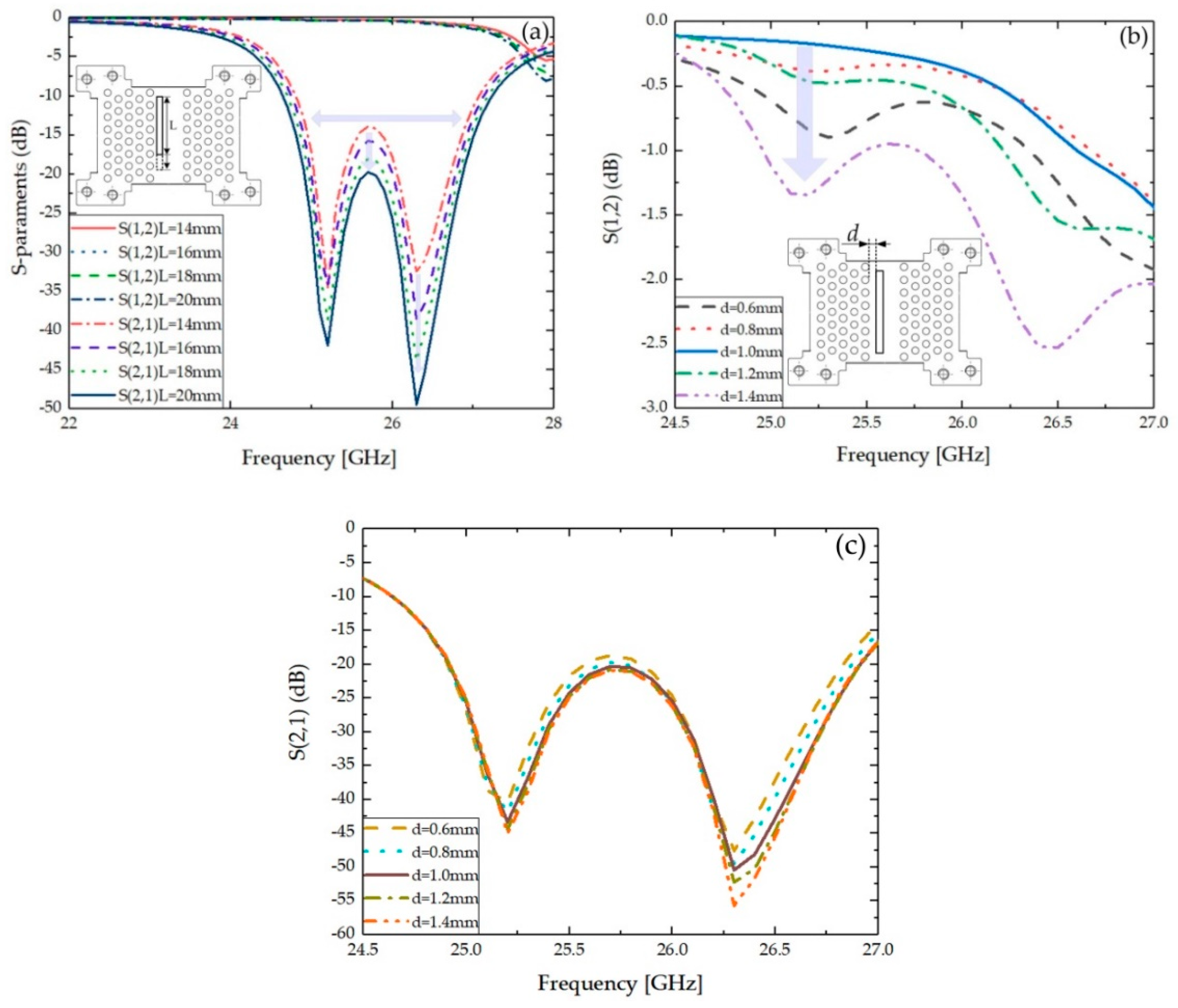
In order to optimize the performance of the MO isolator, we will discuss the effect of ferrite structure parameters on the performance of MO isolator. When the length L of the two ferrite sheets is increased, the positive transmission efficiency of the MO isolator does not obviously change. But the reversed isolation peak of the isolator has a sharp rise with the increasing length, as shown in Figure 7a. When the length of the ferrite sheets increases from 14 to 20 mm, the isolation peak rises gradually from 34.58 to 49.49 dB, and the bandwidth is also broadened 27.28%. The improvements of the MO isolator’s isolation and bandwidth are owed to its unique working principle because the operational principle of our designed MO isolator is the ferromagnetic resonance absorption principle, where longer ferrite sheets can lead to more energy absorption. Thus, the reverse isolation of the MO isolator increases with the length of the ferrite sheets. The operating bandwidth (isolation > 15 dB) of the MO isolator is broadened to be 24.85 to 27.15 GHz in Figure 7a, when the length L of the two ferrite sheets increases to be 20 mm.
Because the forward and reverse attenuation constant of the isolator is related to the size and position of ferrites [24], the optimization design generally minimizes forward attenuation which determined by the position of the ferrites. The H-plane rectangular waveguide resonance isolators were also improved by using ferrites with different materials, structures, and positions [25]. When the distance between the two ferrite sheets and the narrow-edge of waveguide is increasing from 5.59 to 5.84 mm, the loss of the isolator is decreasing, which has been investigated for improving the performance of the isolator in [25]. Thus, we tried to change the position of ferrite sheets in the PCW to optimize the forward transmission efficiency in this work.
In the frequency range of 24.5 to 27.15 GHz corresponding to the bandwidth of the MO isolator mentioned above, the transmission efficiencies’ variation of the isolator are related to the distance d between the ferrite sheets and the boundary of PCW, as shown in Figure 7b. When the distance d deviating from 1 mm increases to 1.4 mm or decreases to 0.6 mm, the transmission efficiencies significantly reduced. However, the distance d hardly influences the isolators’ isolation, which is slightly increasing when the distance is changing from 0.6 to 1.4 mm, as shown in Figure 7c. So the optimal distance between the ferrite sheets and the boundary of PCW is 1 mm. Therefore, the transmission performance of the designed MO isolator can be optimized by finding the most appropriate resonant distance.

4. Conclusions

In this work, a novel MO isolator was proposed based on a high efficiency PCW and two gyromagnetic ferrites. The optimal PCW structure with ultra-wideband characteristic was realized by 3D numerical simulation and experimental verification. The MO isolator was designed by inserting two rectangular gyromagnetic ferrite sheets into the low loss PCW. By using finite element method, the isolation was optimized to be 49.49 dB for the isolator, and its relative bandwidth reaches 8.85%. Furthermore, the effects of ferrite structure parameters on the performance of MO isolator were discussed. The bandwidth of the isolator was broadened to be 24.85 to 27.15 GHz by increasing the length of the ferrite sheets. When the distance between the ferrite sheets and the boundary of PCW was optimized to be 1 mm, the designed MO isolator had an excellent transmission performance.
It should be noted that our MO isolator is relatively simple and easily made. The excellent performance of the PCW and low material loss demonstrate that TLPCs using Al2O3 posts is a promising method for generating an MO isolator or other devices, such as PCs circulators [21,26], in the future integrated communication system. Our designed MO isolator with high isolation and wide bandwidth also provides a potential and feasible scheme for the current research hotspot of 5G communication systems. But the difficulty of processing the ferrite sheets assuredly increases due to the friability of the ferrite, especially when the thickness of the ferrite sheets is too thin, i.e., only 0.5 mm, to be processed by the existing machining partners. In our further work, we may verify the MO isolator by experiments, if we find the high precision laser processing technology similar to [27], which allows to produce cm-scale arbitrary three-dimensional nanostructures with 100 nm feature sizes inside large crystals in the absence of brittle fracture.

Author Contributions

Conceptualization, D.Z. and S.X.; methodology, Y.W. and B.X.; software, Y.W. and B.X.; validation, W.Y., B.X. and Z.D.; formal analysis, W.Y. and B.X.; investigation, W.Y., D.Z. and S.X.; resources, D.Z., J.P. and S.X.; data curation, Y.W. and B.X.; Writing—Original Draft preparation, Y.W.; Writing—Review and Editing, D.Z., S.X. and X.L.; visualization, Y.W. and B.X.; supervision, D.Z. and S.X.; project administration, W.Y.; funding acquisition, D.Z., S.X., X.Z., X.L. and Y.W.

Funding

This work was supported partly by the National Natural Science Foundations of China (61775142, 61171006), China Postdoctoral Science Foundation (2019M653028, 2017M612726), Shenzhen basic research project on subject layout (JCYJ20170412105812811), Natural Science Foundations of Shenzhen University (2019007).

Acknowledgments

The authors would like to acknowledge the Shenzhen Key Laboratory of Micro-Nano Photonic Information Technology and College of Physics and Optoelectronic Engineering of Shenzhen University.

Conflicts of Interest

The authors declare no conflict of interest.

References

  1. Yablonovitch, E. Inhitited spontaneous emission in solid-state physics and electronics. Phys. Rev. Lett. 1987, 58, 2059–2062. [Google Scholar] [CrossRef]
  2. John, S. Strong localization of photons in certain disordered dielectric super-lattices. Phys. Rev. Lett. 1987, 58, 2486–2489. [Google Scholar] [CrossRef]
  3. Bruyant, A.; Lérondel, G.; Reece, P.J.; Gal, M. Allsilicon omnidirectional mirrors based on one-dimensional photonic crystals. Appl. Phys. Lett. 2003, 82, 3227–3229. [Google Scholar] [CrossRef]
  4. Happ, T.D.; Markard, A.; Kamp, M. InP-Based short cavity lasers with 2D photonic crystal mirror. Electron. Lett. 2001, 37, 428–429. [Google Scholar] [CrossRef]
  5. Stockermans, R.J.; Rochon, P.L. Modeling of Photonic Bandgaps in Resonant Waveguide Grating Systems Using a Simple Theory for 1-D Photonic Crystals. J. Lightwave Technol. 2007, 25, 952–956. [Google Scholar] [CrossRef]
  6. Qiu, M.; Jaskorzynska, B. Design of a channel drop filter in a two-dimensional triangular photonic crystal. Appl. Phys. Lett. 2003, 83, 1074–1076. [Google Scholar] [CrossRef]
  7. Akahane, Y.; Asano, T.; Song, B.S. High-Q photonic nanocavity in a two-dimensional photonic crystal. Natural 2003, 425, 944–947. [Google Scholar] [CrossRef]
  8. Akahane, Y.; Mochizuki, M.; Asano, T.; Tanaka, Y.; Noda, S. Design of a channel drop filter by using a donor-type cavity with high-quality factor in a two-dimensional photonic crystal slab. Appl. Phys. Lett. 2003, 82, 1341–1343. [Google Scholar] [CrossRef] [Green Version]
  9. Chutinan, A.; Okano, M.; Noda, S. Waveguides and waveguide bends in two-dimensional photonic crystal slabs. Appl. Phys. Lett. 2002, 80, 1698–1700. [Google Scholar] [CrossRef]
  10. Duan, S.Q.; Chen, Y.P.; Li, G.Z.; Zhu, C.Y.; Chen, X.F. Broadband polarization beam splitter based on a negative refractive lithium niobate photonic crystal slab. Chin. Opt. Lett. 2016, 14, 042301–042304. [Google Scholar] [CrossRef]
  11. Wang, Z.; Fan, S.H. Optical circulators in two dimensional magneto-optical photonic crystals. Opt. Lett. 2005, 15, 1989–1991. [Google Scholar] [CrossRef]
  12. Wang, Y.; Zhang, D.G.; Xu, S.X.; Ouyang, Z.B.; Li, J.Z. Low-Loss Y-junction two-dimensional magneto-photonic crystals circulator using a ferrite cylinder. Opt. Commun. 2016, 369, 1–6. [Google Scholar] [CrossRef]
  13. Jalali, A.A.; Friberg, A.T. Faraday rotation in a two dimensional photonic crystal with a magneto-optic defect. Opt. Lett. 2005, 30, 1213–1215. [Google Scholar] [CrossRef]
  14. Yin, Z.; Ji, D.J.; Lei, L.; Hao, H.; Xiu, H.D.; Liang, Z.X. A 40-Gbit/s 1-to-2 photonic data distributor empploying a single semiconductor optical amplifier. Chin. Phys. Lett. 2011, 28, 064212. [Google Scholar]
  15. Chen, K.X.; Chiang, K.S.; Chan, H.P. Broadband multiport dynamic optical power distributor based on thermooptic polymer waveguide vertical couplers. IEEE Photonics Technol. Lett. 2008, 20, 273–275. [Google Scholar] [CrossRef]
  16. Zhu, Z.H.; Ye, W.M.; Ji, J.R.; Yuan, X.D.; Zen, C. High-Contrast light-by-light switching and AND gate based on nonlinear photonic crystals. Opt. Express 2006, 14, 1783–1788. [Google Scholar] [CrossRef]
  17. Liu, Q.; Ouyang, Z.; Wu, C.J. All-Optical half adder based on cross structures in two-dimensional photonic crystals. Opt. Express 2008, 16, 18992–19000. [Google Scholar] [CrossRef]
  18. Kato, H.; Matsushita, T.; Takayama, A.; Egawa, M.; Nishimura, K.; Inoue, M. Properties of one-dimensional magnetophotonic crystals for use in optical isolator devices. IEEE Trans. Magn. 2002, 28, 3246–3248. [Google Scholar] [CrossRef]
  19. Hiroyuki, T.; Sajeev, J. Compact optical one-way waveguide isolators for photonic-band-gap microchips. Phys. Rev. A 2008, 78, 023804. [Google Scholar] [Green Version]
  20. Haddadan, F.; Soroosh, M. Low-Power all-optical 8-to-3 encoder using photonic crystal-based waveguides. Photonics Net. Commun. 2019, 37, 83–89. [Google Scholar] [CrossRef]
  21. Wang, Y.; Zhang, D.G.; Xu, S.X.; Xu, B.G.; Dong, Z.; Zeng, X.K.; Pei, J.H.; Xu, S.X.; Xue, Q. Four ports double Y-shaped ultra-wideband magneto-photonic crystals circulator for 5G communication system. IEEE Access 2019, 7, 120463–120474. [Google Scholar] [CrossRef]
  22. Gardiol, F.E.; Vorst, A.S.V. Computer Analysis of E-Plane resonance isolators. IEEE Trans. Microw. Theory Technol. 1971, 19, 315–322. [Google Scholar] [CrossRef]
  23. Von Aulock, W.H.V.; Fay, C.E. Linear Ferrite Devices for Microwave Applications; Academic Press: New York, NY, USA, 1968. [Google Scholar]
  24. Lax, B.; Button, K.J. Microwave Ferrites and Ferrimagnetics; McGraw-Hill: New York, NY, USA, 1962. [Google Scholar]
  25. Weiss, M.T. Improved Rectangular Waveguide Resonance Isolators. IRE Trans. Microw. Theory Technol. 1956, 4, 240–243. [Google Scholar] [CrossRef]
  26. Wang, Y.; Zhang, D.G.; Xu, S.X.; Xu, B.G.; Dong, Z. H-Plane cross-shaped waveguide circulator in magneto-photonic crystals with five ferrite posts. Chin. Opt. Lett. 2017, 15, 111601. [Google Scholar] [CrossRef]
  27. Rodenas, A.; Gu, M.; Corrielli, G.; Paie, P.; John, S.; Kar, A.K.; Osellame, R. Three-Dimensional femtosecond laser nanolithography of crystals. Nat. Photonics 2019, 13, 105. [Google Scholar] [CrossRef]
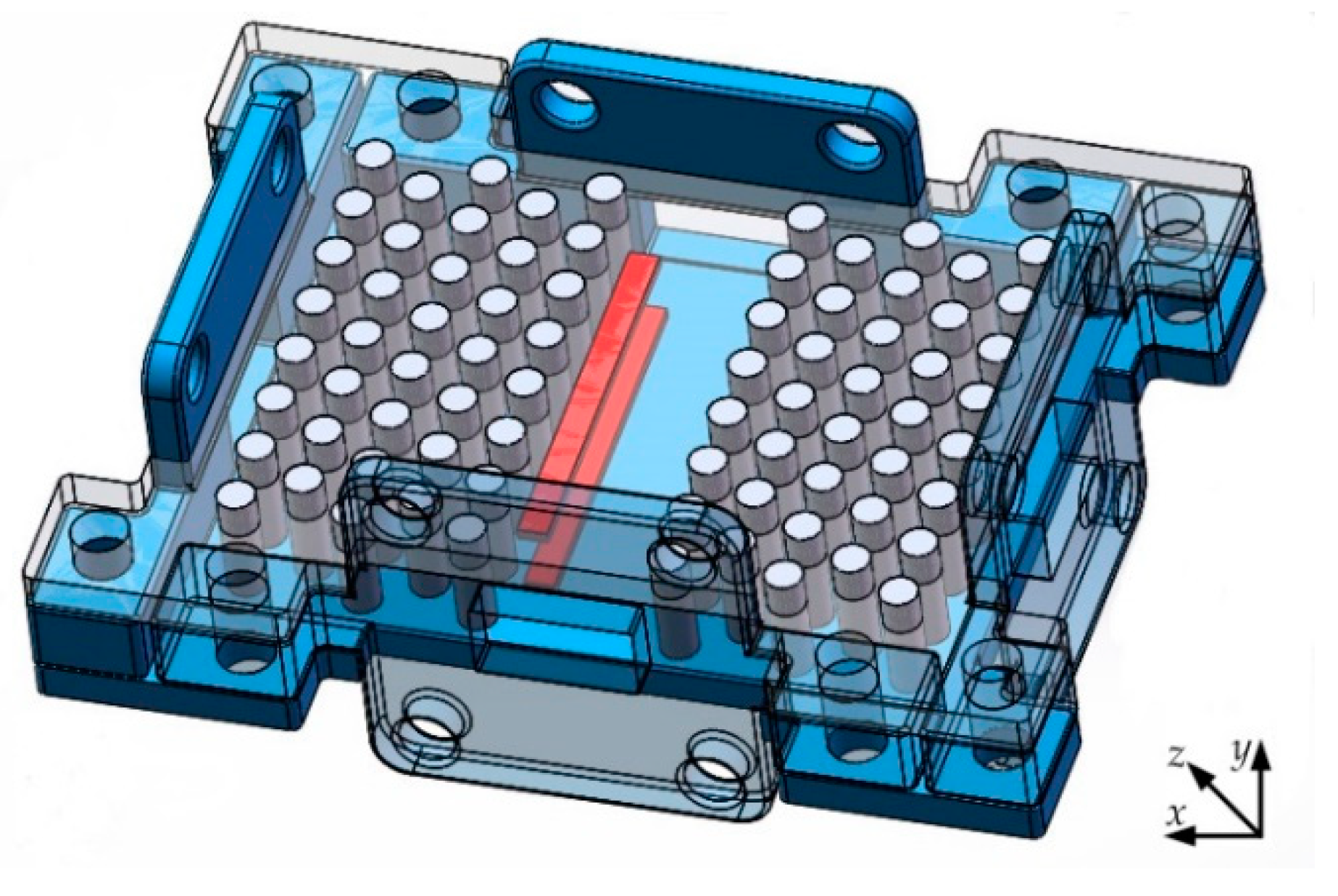
Figure 1. Magneto-optical (MO) isolator based on the photonic crystals waveguide (PCW) and gyromagnetic ferrites.
Crystals 09 00570 g001
Figure 2. The sectional view of the MO isolators.
Crystals 09 00570 g002
Figure 3. The variation of the transmission efficiency of the PCW with frequency.
Crystals 09 00570 g003
Figure 4. (a) The cross section view of the resonance isolator; (b) the variation of the real part of the effective permeability with ω/ω0; and (c) the variation of the imaginary part of the effective permeability with ω/ω0.
Crystals 09 00570 g004
Figure 5. The function of the MO isolator at 26 GHz: (a) Electromagnetic field propagation from Port 1 to Port 2; (b) Electromagnetic field launched from Port 2 but Port 1 isolated.
Crystals 09 00570 g005
Figure 6. The variation of transmission characteristics of MO isolator with frequency.
Crystals 09 00570 g006
Figure 7. (a) The transmission characteristics of MO isolator change with frequency when the length L of ferrite sheets is 14, 16, 18, and 20 mm; (b) the transmission characteristics of MO isolator change with frequency when the distance d between ferrite sheets and the boundary of the PCW is 0.6, 0.8, 1, 1.2, and 1.4 mm; (c) and the isolations of MO isolator change with frequency when the distance d between ferrite sheets and the boundary of the PCW is 0.6, 0.8, 1, 1.2, and 1.4 mm.
Crystals 09 00570 g007