Article

Effect of Al–Mg Alloy Infiltration on Mechanical and Electrical Properties for Carbon/Carbon Composites

School of Physics and Nuclear Energy Engineering, Beihang University, Beijing 100191, China
*
Author to whom correspondence should be addressed.
Crystals 2018, 8(5), 196; https://doi.org/10.3390/cryst8050196
Submission received: 18 March 2018 / Revised: 28 April 2018 / Accepted: 30 April 2018 / Published: 2 May 2018

Abstract

:
Under vacuum Al–Mg alloy, liquids were successfully infiltrated into carbon/carbon (C/C) composites at high temperatures. Then, the mechanical properties, the metallographics, the scanning electron microscope images, the transmission electron microscope images, the X-ray diffraction images, and the energy dispersive spectroscopy results of C/C–Al–Mg composites were analyzed. The result showed that the bending property of C/C–Al–Mg composites reached 183 MPa whereas that of C/C composites totaled 165 MPa. The compressive strength of C/C–Al–Mg measured 206 MPa whereas that of C/C composites amounted to 142 MPa. The flexural strength and compressive strengths of the steeped metal sliders measured 121 and 104 MPa, respectively. The alloy liquid infiltrated into the matrix by forming a “network conduction” structure which reduced the resistivity and improved the conductivity of the composites. The resistivity of C/C–Al–Mg totaled 1.63 µΩm whereas that of C/C was 3.56 μΩm. During infiltration, an excellent wettability was observed between Al and the carbon matrix due to the existence of Al4C3. The friction coefficients of C/C, the steeped metal slide, and C/Al–Mg were 0.152, 0.068, and 0.189, respectively. The properties of C/C–Al–Mg composites meet the performance requirements of locomotive pantograph sliders.

1. Introduction

Carbon/carbon (C/C) composites have attracted considerable attention in various applications due to their unique properties, such as low density, high structural stability, excellent wear resistance, and high temperature resistance [1,2,3,4,5,6,7,8]. C/C composites can be applied in special fields, such as contact strips for pantographs, collector shoes in electric railways, and the current high-speed train system.
The flexural strength of the steeped metal slider ranges from 60 to 150 MPa, and its compressive strength varies between 80 and 120 MPa because of its relatively low mechanical properties. Therefore, the steeped metal slider is easily fractured. High running speeds lead to increased contact breaks and wear rates in the contact strips of current collectors and conductor rails, thus increasing the costs to maintain facilities and decreasing the service life of contact strips and conductor rails. Therefore, it is necessary to improve the mechanical, electrical, and tribological properties of contact strips to meet the requirements of high-speed trains [9,10,11].
It is well known that graphite is an excellent solid lubricant. Hence, the use of graphite is effective in decreasing the friction coefficient. Notably, C/C composites are usually mainly composed of carbon fibers and pyrocarbon [12]. Normally, rough laminar pyrocarbon acts as an excellent solid lubricant during the process of friction. The pyrocarbon or graphite has a layered structure, and during the sliding process, a continuous film of lubricant forms on the tribosurface which prevents direct contact between the two sliding surfaces and results in reduction of the wear rate [13]. Nevertheless, the electrical performance of C/C composites is unsuitable for some applications. Consequently, aluminum magnesium alloy-impregnated C/C composites are considered ideal materials for use in high-speed electrical railways. Recently, carbon fiber-reinforced Mg matrix composites (Cf/Mg composites) have attracted considerable attention from various industrial fields, such as the automobile industry [14]. Some scholars discovered that adding the Al element into magnesium alloy effectively improves the wettability between carbon and magnesium, modifying the interface [15]. Studies have shown that the interface reactivity of carbon and Mg can be controlled by the Al element. Another very important factor is that aluminum is always covered with an oxide layer, especially when it is alloyed with Mg. Some other scholars have shown that the addition of alloying elements can reduce the surface tension of pure aluminum and/or improve wettability. However, it has been reported that after a certain temperature, the oxide layer can be removed and the contact angle reduced. This shows the reason for the decrease in the contact angle [16,17]. Al in the Mg matrix can strongly influence the mechanical properties of Cf/Mg composites due to the formation of the carbide precipitates, Al2MgC2 and Al4C3, at the interface [18,19,20].
In this study, an Al–Mg alloy is impregnated into a carbon-matrix composite in a vacuum environment at different heat treatment temperatures. The mechanical, electrical, and tribological properties of the composites are investigated [21]. Finally, the mechanism of infiltration and different heat treatment temperature effects on the properties of C/C composites are discussed in detail.

2. Experimental Procedure

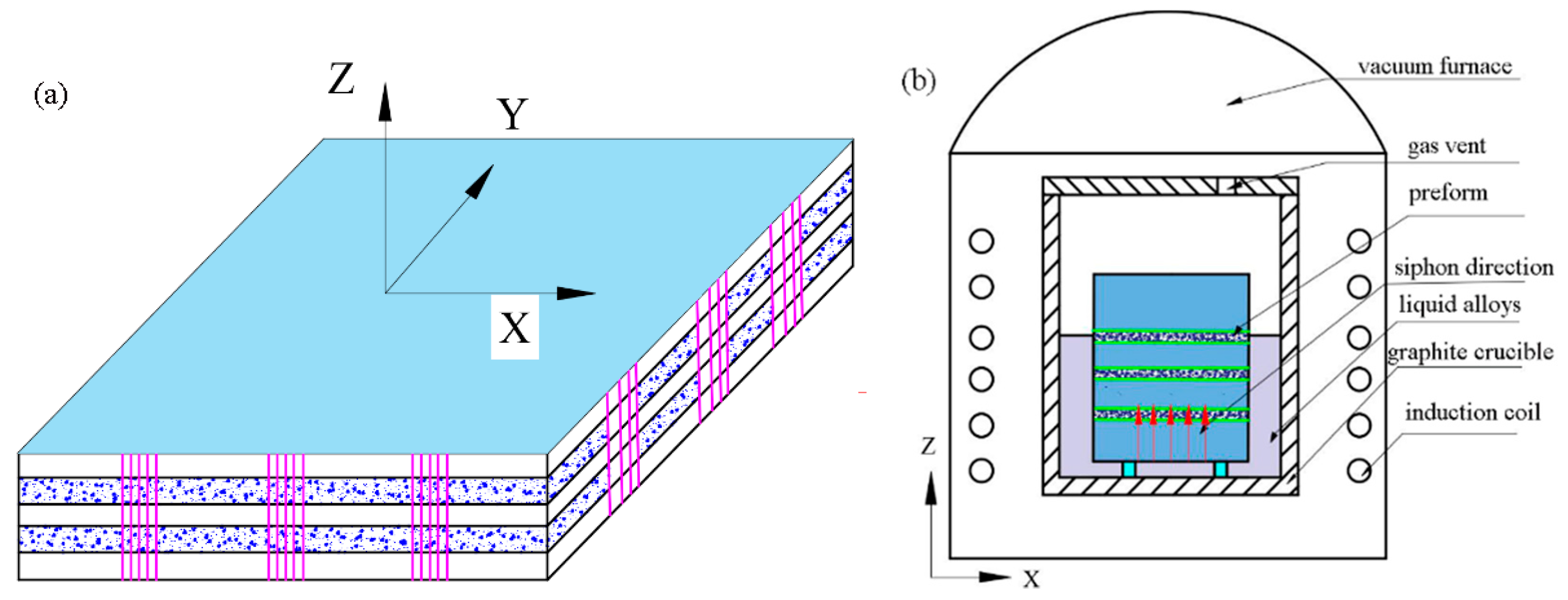
2.1. Preparation of Materials

The carbon fibers were 12K PAN-based (Tuozhan Company, Yantai, China) and possessed a mean filament diameter of 7 μm. In this study, 2D needle-punched carbon felts with a density of 0.55 g/cm3 were used as starting materials [22]. The dimensions of the preform were 100 × 100 × 15 mm, as shown in Figure 1a. The carbon felts were repeatedly fabricated by overlapping layers of 0° non-woven carbon fiber cloth, short-cut fiber web, and 90° non-woven carbon fiber cloth with needle-punching in the vertical direction. Two kinds of C/C composite samples were prepared from the preform carbon felts. Sample A represents the pure C/C composites fabricated directly from the preform using chemical vapor infiltration (CVI) and with a density of 1.78 g/cm3 [23,24,25]. Firstly, for sample B, the preforms were densified using natural gas (mainly containing CH4) and C3H8 through CVI at 1080–1100 °C with a total pressure of 1–5 kPa. Secondly, the preform was densified until the density reached 1.2 to 1.3 g/cm3 through CVI. Finally, the carbon fiber preform was heat-treated at 1900 °C for 2 h. The aluminum-based penetrant merged with the C/C composites and was infiltrated in the aluminum-based mixture: 99.5 wt % Al (50–80 µm, ≥99.5 wt %, purity), 0.5 wt % Mg (50–80 μm, ≥99.5 wt %, purity). All powders were reagent-grade and milled for 2 to 3 h. In the following experiments, the preform was placed in a graphite crucible, and a certain amount of infiltration alloy was added. Then, B0, B1, B2, and B4 were heat-treated at 1000, 1100, 1200, and 1400 °C, respectively, for 30 min in a vacuum. Under high temperatures and in a vacuum, the liquid alloy was slowly immersed in the preform by capillary force, and the C/C–Al–Mg composite material was prepared as described in Figure 1b. Sample B2 refers to the C/C–Al–Mg composite with a density of 2.03 g/cm3. Sample C refers to the steeped metal sliders (Schunk Carbon Technology, Suzhou, China) of pantograph-type current collectors which have good practical applications.

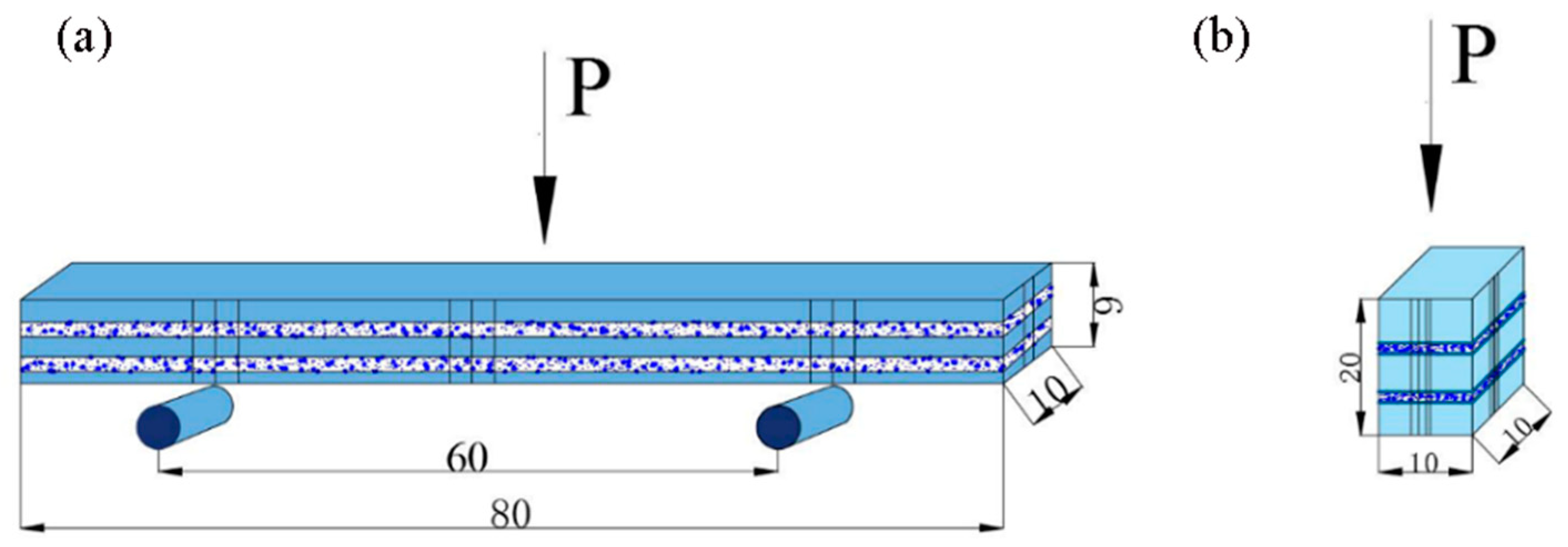
2.2. Property Test and Morphological Analysis

Sample density was determined by the Archimedes principle, and density (ρ in g/cm3) was calculated using the following equation:
ρ = m a m b m c ,
where ma (g) represents the weight of the dried sample, and mb (g) refers to the sample boiled in water for 2 h, removed, and cooled. mc (g) is the weight of the sample in deionized water.
Three-point bending tests were performed to determine the mechanical properties of the obtained materials. From Figure 2a, the sample of dimensions 80 × 10 × 6 mm was partially cut from the preform along the X–Y direction. The loading direction was parallel to the Z-direction, and spanned 60 mm. To ensure reproducibility, the researchers tested five samples for each material. The nominal bending stress, σ z was calculated from the following equation:
σ z = 3 PL 2 bh 2 ,
where σ z represents flexure strength (MPa), L corresponds to the span of the bend test (mm), P is the maximum load (N), b denotes the width of the specimen (mm), and h is the specimen’s thickness (mm).
As shown in Figure 2b, compressive tests were performed on samples with dimensions of 10 × 10 × 20 mm with a loading direction along the Z-direction. To ensure reproducibility, five measurements were conducted for each type of material. The nominal bending stress, σ t was calculated from the following equation:
σ t = F S ,
where σ t is the compressive strength (MPa), F refers to the maximum load (N), and S is the cross-sectional area (mm2).
The friction coefficient was determined using a block-on-disk wear test machine (MFT-R4000, Lanzhou Hua Hui Instrument Technology Co., Ltd., Lanzhou, China). The tested samples were processed at sizes of 10 × 10 × 10 mm and were rubbed against a hardened steel ball with an outer diameter of 6 mm. Wear tests were performed under dry sliding conditions and a normal load of 15 N. The numerical analysis was performed using the following formula:
μ = F N ,
where μ refers to the friction coefficient, F is the friction force (N), and N represents the normal load.

2.3. Electrical Resistivity Measurements

The electrical resistivity of specimens was measured using a direct current and low electrical resistor (TH2512B) according to the JB/T 2664.1-1999 standard in a normal atmosphere. Tested samples with dimensions of 50 × 5 × 2 mm were processed. The reproducibility and stability of the process was ensured, with each specimen type measured five times to obtain the averaged value. The electrical resistivity was calculated using the following formula:
ρ = RS L ,
where ρ corresponds to electrical resistivity (μΩm), R is the electrical resistance (μΩ) determined in the resistor, S stands for the area of the cross section (m2), and L denotes the length of specimens (m).
The test method for penetration depth was as follows: the specimen, obtained after impregnation, was divided, and a height gauge (Nscing Es, 889-101, Nscing Ltd., Nanjing, China) was used for measurement. The microstructures of the samples were analyzed using metallography (OLYMPUS PMG3, Olympus Corporation, Tokyo, Japan), scanning electron microscopy (SEM, S-4800, Hitachi, Tokyo, Japan), energy dispersive spectroscopy (EDS), and transmission electron microscopy (TEM, Model JEM-2100, JEOL Ltd., Tokyo, Japan) operating at an accelerating voltage of 200 kV. X-ray diffraction (XRD, Model D/Max 2500PC, Rigaku, Tokyo, Japan) with Cu Kα radiation was used to analyze the phase structures.

3. Results and Discussion
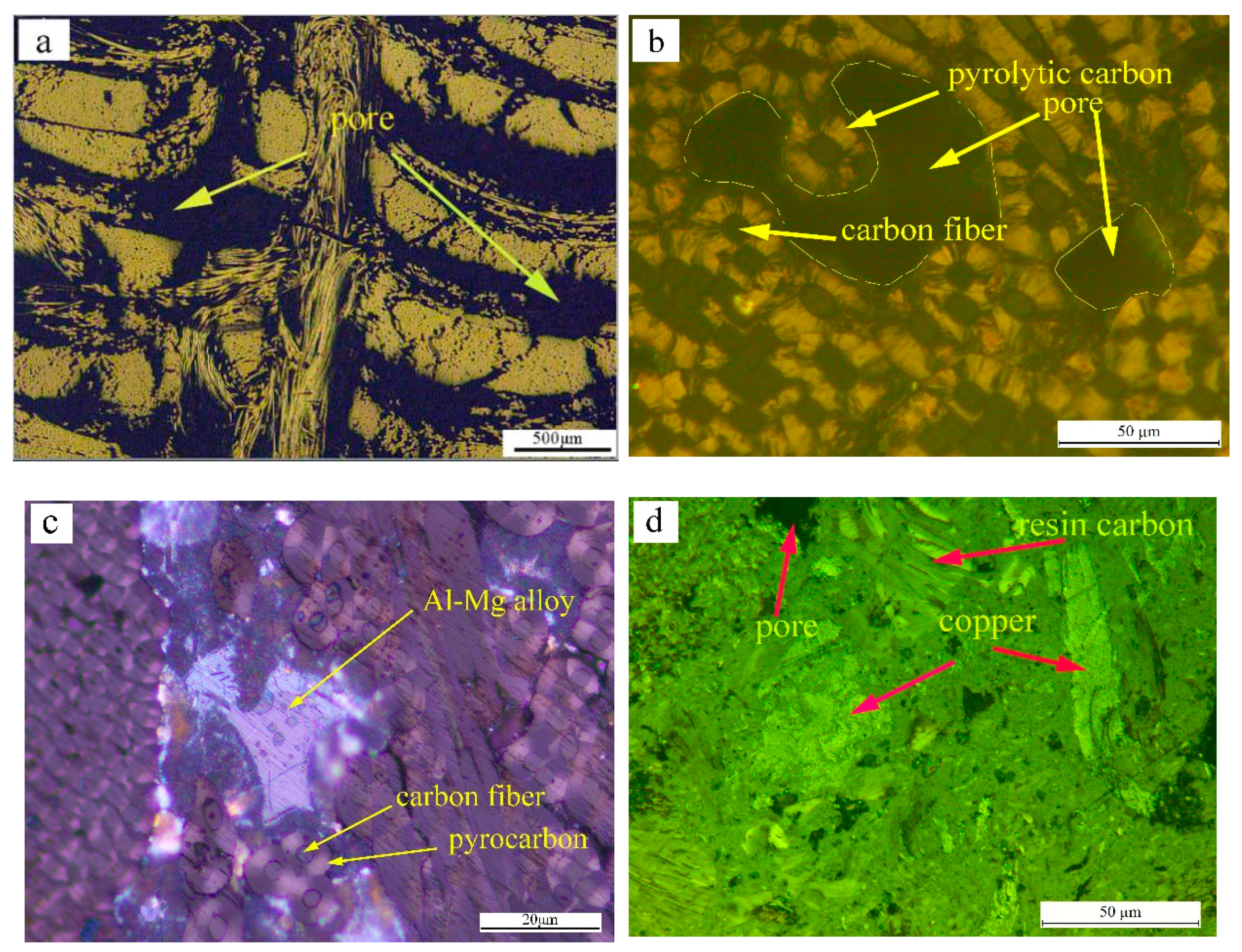
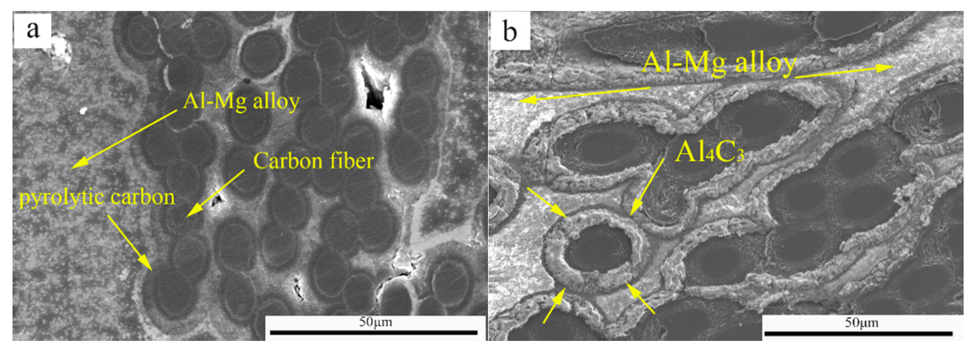
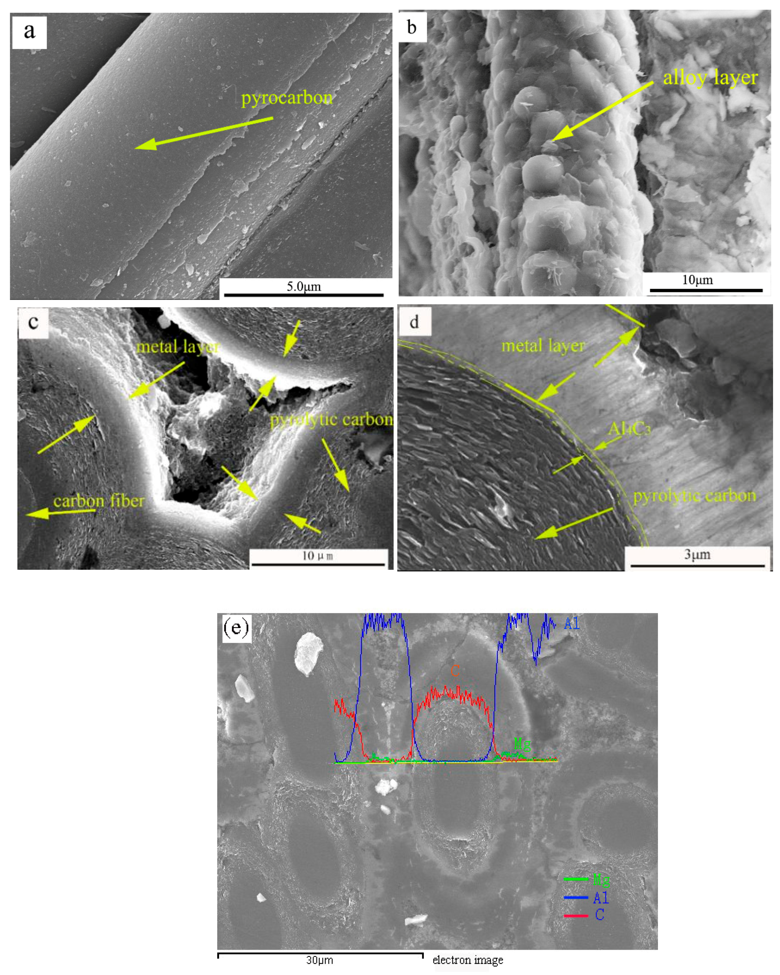
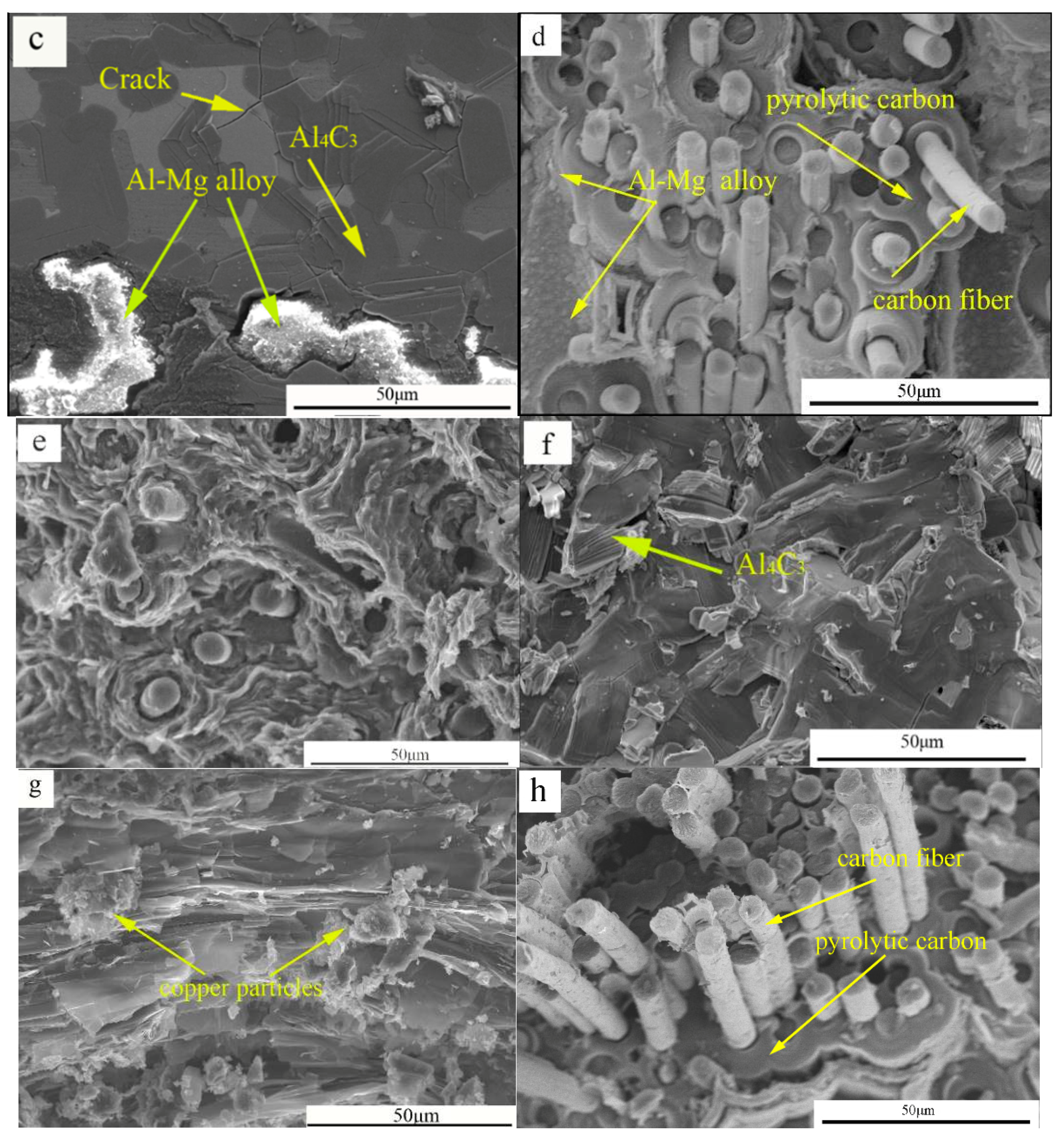
3.1. Microstructure

Figure 3a shows that the C/C composites possess numerous matrix crevices, which provides the channels for the liquid alloy. Figure 3b shows the XY direction, which is parallel to the liquid alloy direction. Figure 3c illustrates the YZ direction, perpendicular to the liquid alloy direction. As shown in Figure 3b, the darker region represents the carbon matrix or carbon fiber, and the carbon fiber is wrapped with pyrolytic carbon.
Figure 3c shows the compact combination of the aluminum–magnesium alloy and carbon substrate and the surface of pyrolytic carbon uniformly coated with a metallic alloy. The interface of pyrolytic carbon and the metal layer was compacted, and a “network conduction” structure formed in the matrix. On one hand, the Al–Mg alloy liquids filled the crevice of C/C by capillary force at high temperatures and in a vacuum. On the other hand, the electrical channels of the Al–Mg alloy were established, reducing the resistivity of the composite material. From the metallographic diagram, the alloy liquids infiltrated the C/C preform to form a distinct “network structure.” For sample B2, Figure 3c shows that the continuous and uniform electrical network of the aluminum–magnesium phase formed in the composite.
Figure 3d shows the loose and porous microstructure of the steeped metal slider and its generally poor mechanical properties. A few copper particles are, remarkably, distributed in the voids, adequately explaining the decrease in electrical resistivity.

3.2. Mechanical Properties and Fracture Behavior of Composites

Matrix modification significantly influences the mechanical properties of C/C composites. As illustrated in Figure 4, the flexural strength of C/C–Al–Mg materials first increased and then decreased as the heat treatment temperature increased. As the temperature increased from 1200 to 1400 °C, the Al–Mg alloy that infiltrated into the matrix further consumed the pyrolytic carbon and formed carbide, thereby resulting in a significant decrease in the mechanical properties of the composite.
The infiltration depth of the alloy increased monotonically as the heat treatment temperature increased under a constant infiltration time. The bending properties of the material reached a maximum at 1200 °C. The flexural strength had a 183 MPa load in the Z-direction, and the infiltration depth was approximately 6.80 mm. With the above experimental results, the wettability of the material improved by increasing the heat treatment temperature. When the reaction temperature exceeded 1200 °C, the mechanical properties of the material decreased significantly. Therefore, for infiltration, the optimum reaction temperature is 1200 °C. Figure 5a,d show the loose and porous microstructure of C/C–Al–Mg and its generally poor mechanical properties. Figure 5b,e illustrate the compact microstructure of C/C–Al–Mg and its excellent mechanical properties. The bending properties totaled 183 MPa, and the compression performance approximated 206 MPa. Figure 5c,f show that the microstructure of C/C–Al–Mg changed. The material mainly comprised Al4C3 and Al–Mg alloy. Consequently, the mechanical properties of the material decreased rapidly. Figure 5g shows the weak flexural strength of the steeped metal slider composites and its brittle characteristic. A small amount of copper particles was observed in the fracture morphology assessment. This phenomenon can be attributed to the lack of carbon fiber in the matrix during the fracture process [26]. Figure 5h shows the fracture micrographs of the C/C composite, with many fibers or fiber bundles pulled out. Obviously, adding elements can improve the mechanical properties of the composites. What is more, with an increase in temperature, the wettability of the composite can be improved [27,28].
Figure 5e shows the C/C–Al–Mg material bending fracture with carbon fibers pulling out or debonding and with fiber lengths at the micron level. Furthermore, the carbon fiber debonding results in cracks or holes. The extraction of pyrolytic carbon and Al–Mg alloy on the surface of carbon fiber shows that the penetration of aluminum also improves the bonding strength between the matrix and carbon fiber. The interfacial bonding strength of aluminum and carbon was stronger than that of C/C materials, which resulted in a shorter pullout length of the carbon fiber [29]. The difference in the interfacial bonding strength between C/C and C/C–Al–Mg can be attributed to the good wettability of aluminum and the improved strengthening effect of the matrix, resulting in enhanced fracture stress. However, the flexural strength of C/C measured 165 MPa, whereas the flexural strength of C/C–Al–Mg was 183 MPa, loaded in the Z-direction, as shown in Figure 6a. The compressive strength of C/C and C/C–Al–Mg reached 142 and 206 MPa, respectively. Nevertheless, smooth surfaces were observed for pitch coke, as shown in Figure 5g, and only a small quantity of the copper particles of the matrix was displayed. The flexural strength of the steeped metal slider material reached 121 MPa. Compared with the industrial standard, the bending strength of the pantograph was more than 80 MPa higher, and C/C–Al–Mg was able to meet the requirements of the pantograph material. Figure 6a shows that the compressive strengths of C/C–Al–Mg and the steeped metal slider material totaled 206 and 104 MPa, respectively. Finally, the results showed that C/C–Al–Mg possesses better mechanical properties than the steeped metal slider.
Figure 6b shows the typical flexural stress–displacement curve of the sample loading in the Z-direction. The figure also shows similar characteristics of stress–displacement for C/C. For pure C/C, the displacement increased with increasing load, and a specific cracking characteristic was observed when loading was higher than the maximum. The displacement also caused no brittle fractures. However, for C/C–Al–Mg, the displacement increased with increasing load, and the brittle fracture characteristic was observed when loading was higher than the maximum. As a result, C/C–Al–Mg possessed better flexural strength than pure C/C. Figure 6c shows the typical compressive stress–displacement curve of the samples loaded in the Z-direction. In the linear stage, the slope of the stress–displacement increased in the following order: C/C then C/C–Al–M. This result indicates the better compressive strength of C/C–Al–Mg compared to C/C.

3.3. Friction Coefficient and Frictional Behavior of the Composites

Figure 7a shows that friction coefficients of composites increased monotonously. The steeped metal slider composite mainly consisted of carbon, copper particles, graphite, and pitch coke. Remarkably, the graphite–matrix interface is an excellent solid lubricant. The addition of graphite can effectively reduce the friction coefficient and wear rate of the material. Figure 7b illustrates three kinds of friction curves at a 15 N load and lubricated in dry conditions. The test time was controlled at 10 min. A time of approximately 4 mins was needed for C/C to stabilize; this period was shorter than the 6 min observed for C/C–Al–Mg. For the steeped metal slider, the friction coefficient changed irregularly, but it measured less than 0.20 in most cases. The steeped metal slider material formed a lubricating film on the contact surface relatively easily, but the strength of lubricating film meant it was extremely prone to breaking down.
As shown in Figure 7a, the average friction coefficient of the steeped metal slide composite was 0.068, whereas the friction coefficient of the C/C composite reached 0.152. When the aluminum–magnesium alloy infiltrated into the C/C composites, the friction coefficient increased from 0.152 to 0.189. During the friction process, the steeped metal slider can easily form a lubricating film and a larger area of actual contact [30]. However, the C/C composites consist of pyrolytic carbon and carbon fiber. During the process of friction, carbon fibers act as a skeleton support. The actual contact area with the counterpart is small, thereby resulting in difficulties in the formation of a lubricating film [31,32]. As a result, the friction coefficient of the steeped metal slide was the smallest. When the alloy liquid infiltrated the C/C material to fill defects, the alloy layer wrapped the pyrolytic carbon, which then wrapped the carbon fibers, indicating its remarkably good supporting role. Thus, a point-to-face contact pattern was more easily obtained during the rubbing process, leading to an improvement in surface hardness, increase in wear resistance, and increase in the friction coefficient of the material [33,34].
Figure 8 shows the SEM micrographs of the worn surfaces on the composites. The entire pyrolytic-carbon lubricating film can be formed on the worn surfaces of composites, like those illustrated in Figure 8a. The formation of a stable transfer layer protected the mating surfaces from further direct contact, leading to a mild wear model. For the investigated composite, the most important feature was the existence of carbon fibers, whose intensity was much more significant than that of a carbon matrix. Carbon fibers in the carbon matrix protected the softer matrix during abrasive sliding and strengthened the matrix, thus enhancing the resistance to plastic deformation and penetration as well as the cutting of the steel ball into the surface of composites.
The materials between the worn surface and micro-cracks peeled off. Peeling pits were formed, as displayed in Figure 8b. Mechanical and thermal stresses were continuous between contact asperities under constant load, implying the relationship of localized fatigue phenomena to the displacement of areas. These cyclic fatigue phenomena caused the material to generate peeling pits. When the alloy was infiltrated into the C/C composites, the lubricating film contained metal particles. Some metal particles increased the hardness of the lubricating film, and other metal particles fractured or loosened from the matrix. Accordingly, numerous particles of large wear debris were scattered on the worn surface, contributing to severe abrasive wear. A few peeling pits and cracks were also observed on the worn surface, suggesting a mechanism for adhesive wear.
As shown in Figure 8c, the steeped metal material easily formed a lubricating film during the rubbing process, and it easily ruptured because of its high microcrystalline mobility. The tribo-surface showed a few micro-cracks caused by friction force and heat. Therefore, the wear mechanism of the composites mainly included adhesive wear and abrasive wear [35].

3.4. Electrical Performance

In the experiment, C/C composites were impregnated with metal elements to improve their electrical conductivity. The resistivities of the steeped metal slider, C/C–Al–Mg composites, and C/C composites reached 11.6, 1.63, and 3.56 µΩm, respectively. The results show that the resistivity of the composites decreased, and the electrical conductivity increased significantly when metal elements penetrated C/C composites. Figure 9a,b show that the C/C–Al–Mg formed a “network conduction” structure in the matrix which significantly improved the channels of free electron transport. This phenomenon resulted from the formation of conductive filler in the composite material within the conductive path.
The resistance of an elementary unit can be depicted by using equivalent circuit models. The two units can be considered as parallel circuit models, and the resistance values of the two units in the DC electrical field can be expressed using Equations (6) and (7) [36]. The R2 value is lower than the R1 value because of the introduction of the Al–Mg alloy, indicating that the electric conductivities of the samples mainly depend on the Al–Mg alloy:
1 R 1 = 1 R c f + 1 R p y c
1 R 2 = 1 R c f + 1 R p y c A l M g
The increase in conductivity is due to additional flow paths provided by the Al–Mg alloy. In Figure 9c,d the migrating electrons and hopping electrons mode were displayed. Electrons that migrate in carbon fiber are considered migrating electrons, whereas electrons jumping between carbon fibers and Al–Mg alloy are identified as hopping electrons. The presence of hopping electrons in the system can improve the microcurrent in the conductive network. As a result, the electrical conductivities of the composites increase with a sufficient Al–Mg alloy concentration.

4. Discussion

C/C composites exhibit a completely pyrolytic carbon matrix that coats the carbon fibers. The interface between the matrix and fibers represents good adhesion between these materials and modest flexural strength. However, the adhesion between the pyrolytic carbon matrix and carbon fibers increased when pyrolytic carbon fibers were coated with Al or Mg particles and yielded a small quantity of Al4C3, as shown in Figure 10a–d. Figure 10e illustrates the phenomenon of the Al–Mg alloy surrounding pyrolytic carbon. This result can be attributed to the good wettability observed between Al and pyrolytic carbon [37]. For C/C–Al–Mg composites with carbides at the interface, the formation of carbides consumed the C element of carbon fibers, transforming interfacial bonding into chemical bonding from mechanical bonding, as shown in Figure 10f. Finally, the C/C–Al–Mg composites showed increased mechanical properties compared with the C/C composites. After the infiltration of alloy, the carbides of the composites were formed according to the following chemical Equation:
4 Al ( l ) + 3 C ( S ) = Al 4 C 3
As shown in Figure 11a, a relationship was observed between the wetting angle of infiltration and tension. As shown in the figure, θ is called the wetting angle. The equilibrium value of the contact angle (θ), which is used to define the wetting behavior of liquids, obeys the classical equation of Young (see Equations (9) and (10)). In the experiment process, Al-pyrolytic carbon systems produced a small quantity of Al4C3, and the interface reaction product promoted wetting, as shown in Figure 11b,c. Over the last few decades, several studies have investigated the wetting behavior of Al-pyrolytic carbon systems. As a reactive wetting system, the final or steady contact angle should be equal to or close to the equilibrium contact angle of the liquid on the reaction product, Al4C3. The wetting behavior of the reaction product is governed by the formation of adsorption layers at the interface, rather than by the subsequent nucleation and growth of the reaction product [38]. The wettability will not be improved by the chemical reaction itself. Chemical reactions involve an exchange of atoms. Consequently, in the Al-pyrolytic carbon system, the final contact angle on the reaction product, Al4C3, is lower than the initial contact angle on the original substrate, graphite, as shown in Figure 11c,d. Moreover, a crystal structure also affected the shape of Al4C3 (Figure 11e). The crystal structure of Al4C3 was constituted by the layers of Al and C, which are alternately stacked on each other. This kind of structure was also observed in carbon nanotube-reinforced aluminum silicon composites (Srinivasa et al., 2009). The reaction of aluminum and carbon is complex in the process of infiltration. It is necessary to research the reaction mechanism involved in the process of infiltration. Some scholars believe that the reaction is controlled by the formation of particles of carbide at the interface, which prevents the reaction from proceeding [39,40,41].
δ g · s = δ l · s + δ g · l · cos θ
cos θ = δ g · s δ l · s δ g · l
where δ represents the surface tension and the subscripts s, g, and l refer to solid, gaseous, and liquid states, respectively. When δg∙s > δl∙s, cos θ > 0, and θ < 90°, the alloy can wet the graphite material. When δg∙s < δl∙s, cos θ < 0, and θ > 90°, the alloy cannot wet the graphite material.
During friction, the entire graphite lubricating film can be formed on the worn surface of C/C–Al–Mg composites with metal particles, as shown in Figure 8b. The formation of stable transfer layer protected the mating surfaces from further direct contact, leading to mild wear [42,43,44,45,46,47]. The metal particles in the carbon matrix provided protection to the softer matrix during abrasive sliding and strengthened the matrix. The C/C composites lacked the particle hardness in the matrix. Consequently, the graphite lubricating film of C/C composites easily degraded during friction, thereby explaining the increase in the friction coefficient of the C/C–Al–Mg material.
Figure 9 displays the SEM micrographs of composites with metal practice reinforcement. The figure also shows that a continuous and uniform electrical network of the Al–Mg phase formed in the matrix, and the electrical resistivity of the composite measured less than that of the steeped metal slider for collectors currently used in railways (11.6 µΩm). Hence, a continuous electric network of the Al–Mg phase can be formed, thereby sufficiently explaining the decrease in electrical resistivity compared with that of C/C composites.
During the growth process, Al4C3 formed a needle-like morphology on the surface of pyrocarbon, as shown in Figure 12b. Finally, the main growth direction of Al4C3 was longitudinal [48]. The longitudinal growth speed of Al4C3 was controlled by diffusion and Ostwald ripening [49]. The Ostwald ripening process is confirmed by the significant change in the Al4C3 particle size. The diffusion speed was affected by the diffusion of not only the elements in the matrix, but also by Al and C in Al4C3 [50]. The lateral growth speed was mainly controlled by two-dimensional nucleation, which formed at the interface. The different growth speeds made the shape of Al4C3 a needle-like microstructure. Figure 12b showed the TEM photos of the microstructure of Al4C3, which was 567.9 nm in length and 110.8 nm in width. The ratio of length to width was about 6.38. It had the tendency to grow in thickness in the direction of the end portion. Figure 12c shows the end portion of Al4C3.

5. Conclusions

In this work, C/C–Al–Mg composites were prepared by infiltrating the alloy under a vacuum and at high temperatures. This kind of material could be used as an ideal new pantograph material. The experimental results led to the following conclusions.
(1)
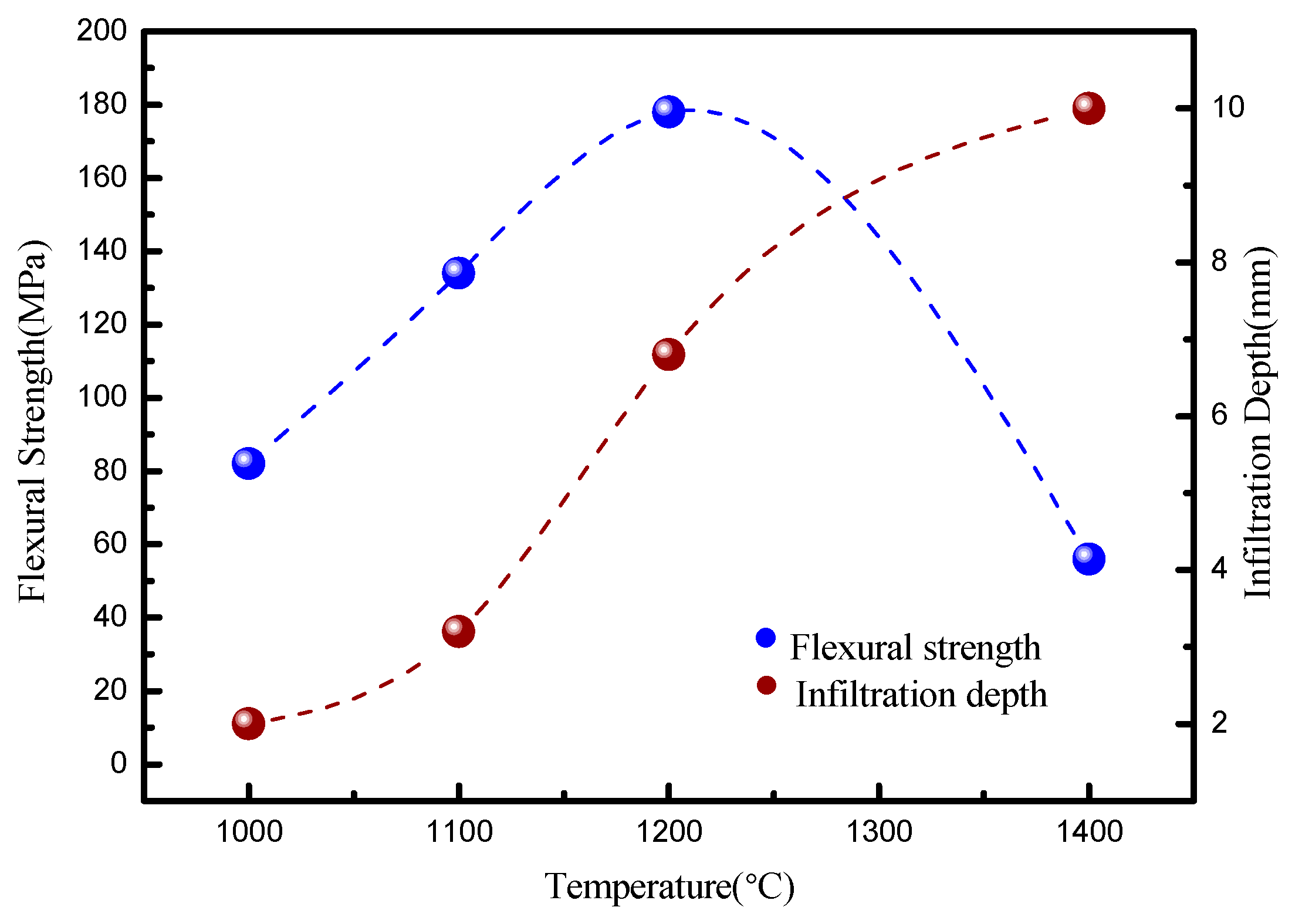
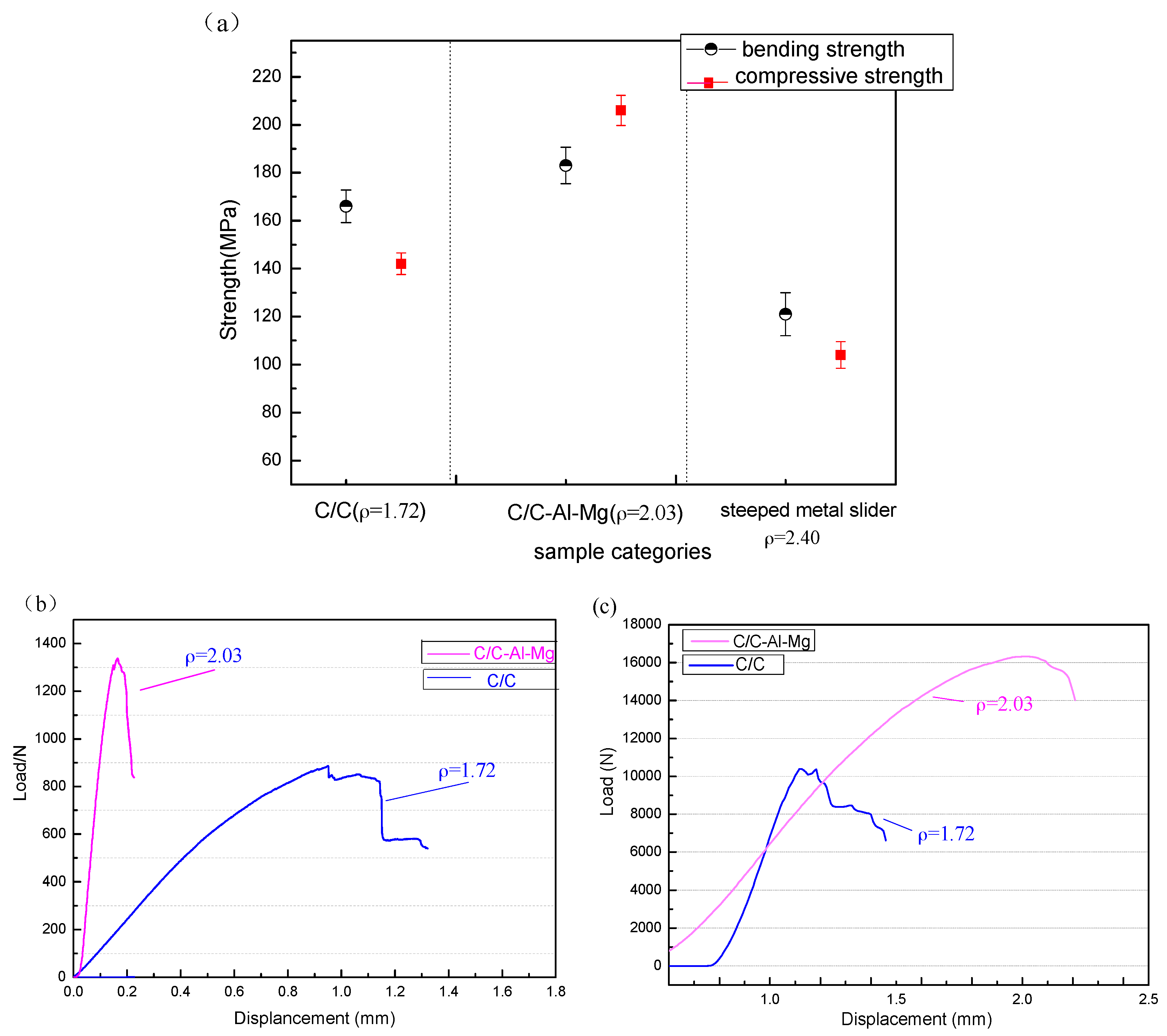
The results showed that flexural strength of C/C–Al–Mg composites was 183 MPa, whereas the bending property of C/C composites reached 165 MPa. The compressive strengths of C/C–Al–Mg and C/C composites measured 206 and 142 MPa, respectively. The flexural strength and compressive strength of the steeped metal slider material reached 121 and 104 MPa, respectively. Compared with industry standards, the flexural strength of the powder metallurgy of the pantograph was higher than 80 MPa, whereas C/C–Al–Mg met the requirements of pantograph materials.
(2)
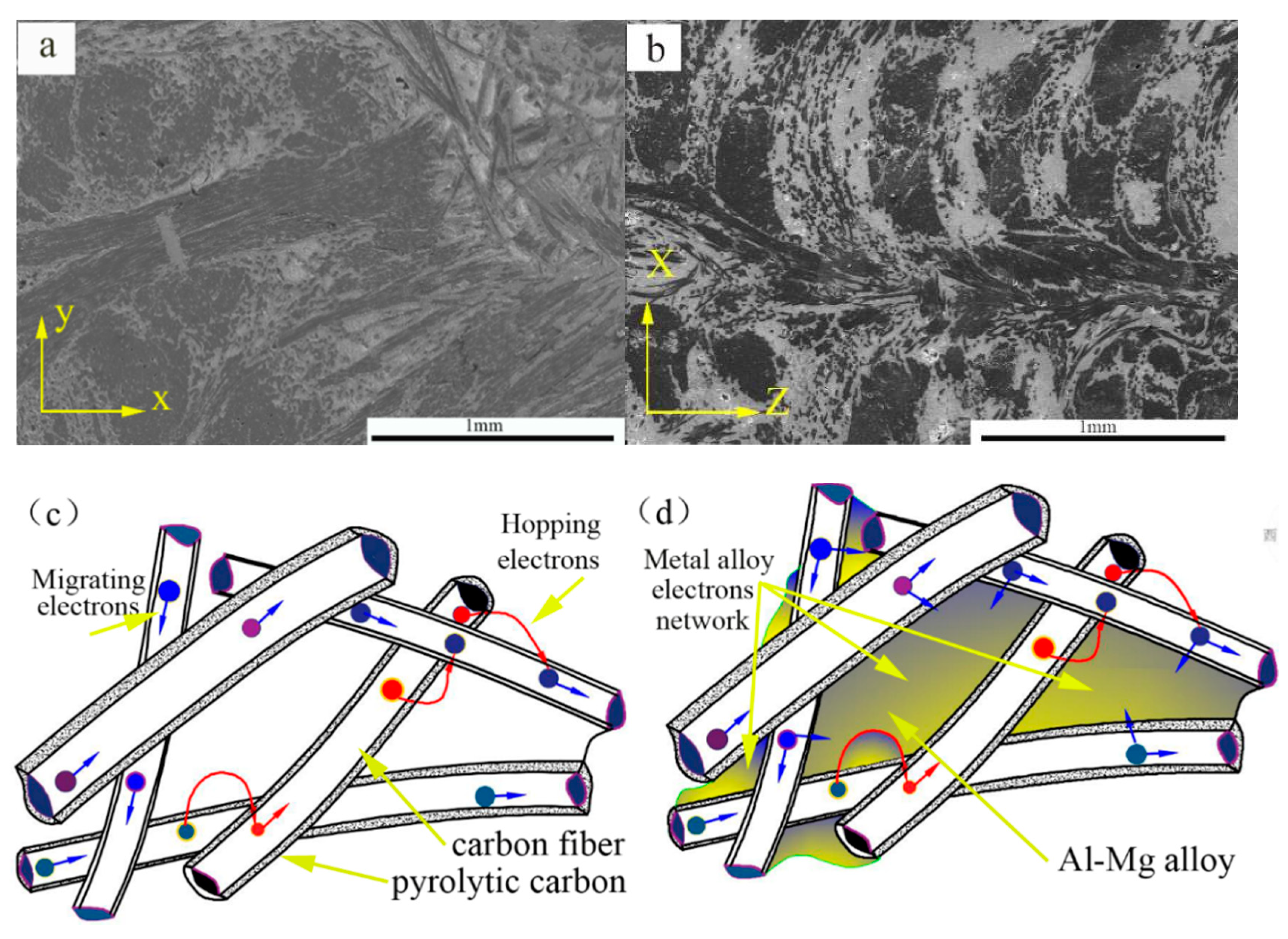
The resistivities of C/C–Al–Mg and C/C composites were 1.63 and 3.56 µΩm, respectively. C/C–Al–Mg had a good electrical conductivity, which was considerably less than the 12 µΩm industry standard of pantograph conductivity materials.
(3)
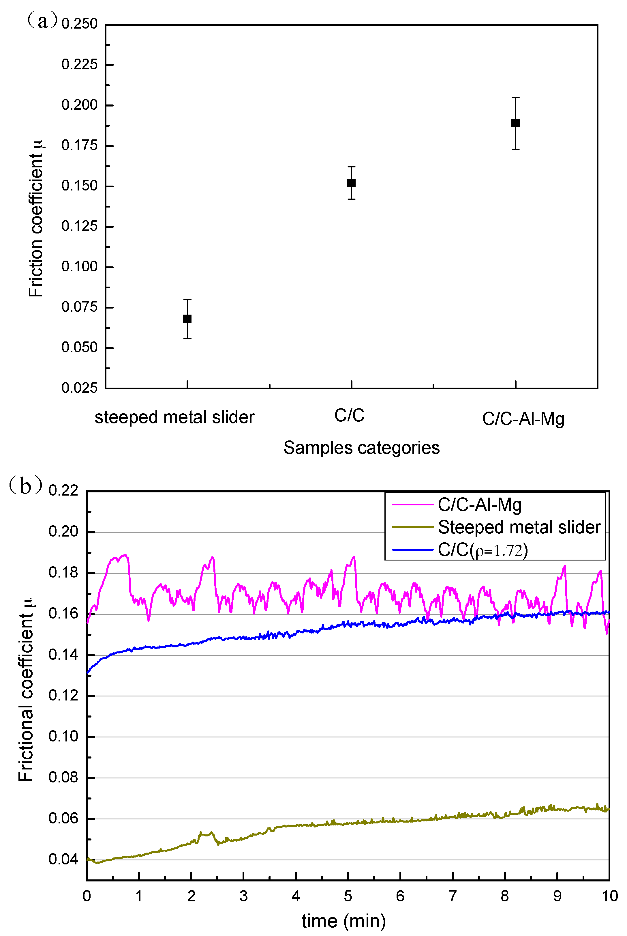
The friction coefficient of the steeped metal slide composite was 0.068 whereas that of C/C composite was 0.152. When the Al–Mg alloy infiltrated the C/C composites, the friction coefficient increased from 0.152 to 0.189.
(4)
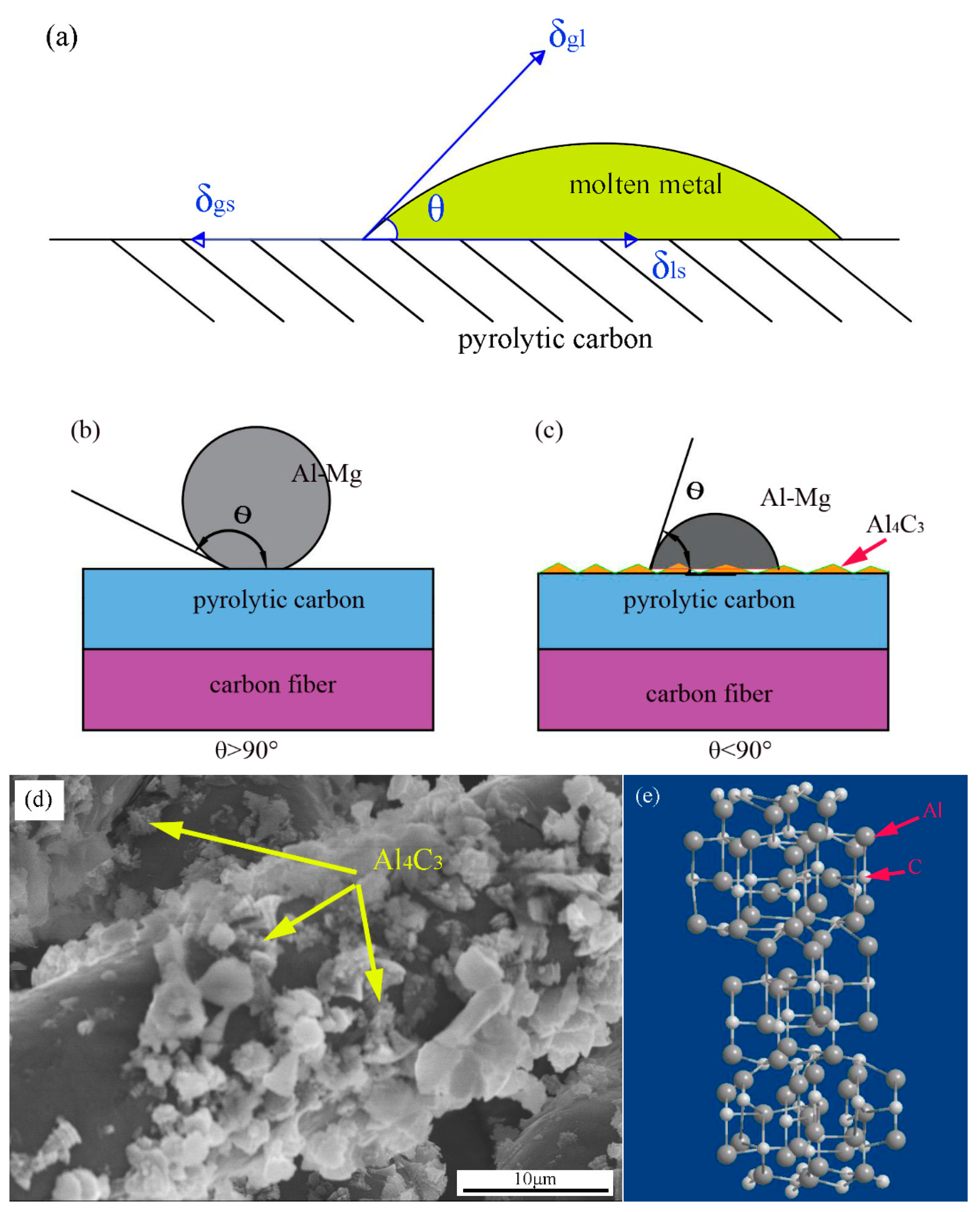
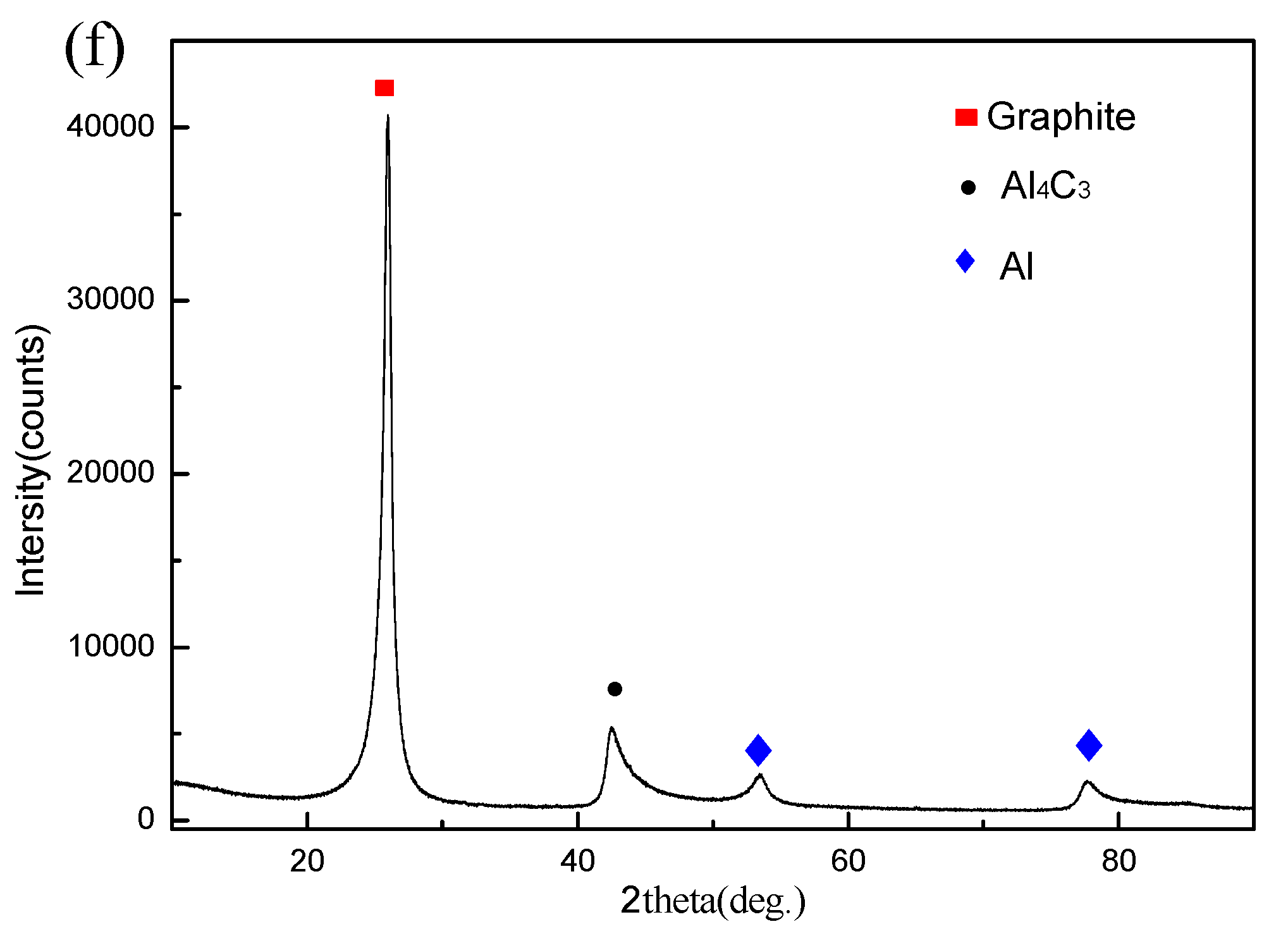
The final contact angle on the reaction product, Al4C3, was lower than the initial contact angle on the original substrate, graphite.

Author Contributions

L.C. and R.L. conceived and designed the experiments; L.C. performed the experiments; L.C. analyzed the data; G.C. contributed analysis tools; L.C. wrote the paper.

Acknowledgments

The authors acknowledge the National Natural Science Foundation of China (No. 21071011).

Conflicts of Interest

The authors declare no conflict of interest.

References

  1. Luo, R.Y.; Liu, T.; Li, J.S. Thermophysical properties of carbon/carbon composites and physical mechanism of thermal expansion and thermal conductivity. Carbon 2004, 42, 2887–2895. [Google Scholar] [CrossRef]
  2. Sheehan, J.E.; Buesking, K.W.; Sullivan, B.J. Carbon-carbon composites. Ann. Rev. Mater. Sci. 1994, 24, 19–44. [Google Scholar] [CrossRef]
  3. Yuan, Q.L.; Li, Y.L.; Li, H.J.; Li, S.P.; Guo, L.J. Quasi-static and dynamic compressive fracture behavior of carbon/carbon composites. Carbon 2008, 46, 699–703. [Google Scholar]
  4. Fei, Y.B.; Lu, J.H.; Li, H.J.; Guo, L.J.; Chen, Z.S. Influence of heat treatment temperature on microstructure and thermal expansion properties of 2D carbon/carbon composites. Vacuum 2014, 2, 51–53. [Google Scholar] [CrossRef]
  5. Yuan, X.Y.; Liu, G.H.; Jin, H.B.; Chen, K.X. In situ synthesis of TiC reinforced metal matrix composite (MMC) coating by self-propagating high temperature synthesis (SHS). J. Alloys Compd. 2011, 30, 301–303. [Google Scholar] [CrossRef]
  6. Liang, Y.H.; Wang, H.Y.; Yang, Y.F.; Wang, Y.Y.; Jiang, Q.C. Evolution process of the synthesis of TiC in the Cu-Ti-C system. J. Alloys Compd. 2008, 452, 298–303. [Google Scholar] [CrossRef]
  7. Nitai, C.A.; Suman, C.; Naresh, C.M.; Pranab, S.; Tapas, K. Effect of thermally reduced grapheme oxide on mechanical properties of woven carbon fiber/epoxy composite. Crystals 2018, 8, 111. [Google Scholar]
  8. Liu, F.C.; Cao, Y.; Yi, M.D.; Xie, L.H.; Huang, W.; Tang, N.J. Thermostability, photoluminescence, and electrical properties of reduced grapheme oxide-carbon nanotube hybrid materials. Crystals 2013, 3, 28–37. [Google Scholar] [CrossRef]
  9. Kubo, S.; Kato, K. Effect of arc discharge on wear rate of Cu-impregnated carbon contact strip in unlubricated sliding against Cu trolley under electric current. Wear 1998, 216, 172–196. [Google Scholar] [CrossRef]
  10. Matsuyama, S. Electric contact tribological behavior of pantograph. Toyo Denki Giho 1995, 91, 52–60. [Google Scholar]
  11. Feng, Y.; Zhang, M.; Xu, Y. Effect of the electric current on the friction and wear properties of the CNT-Ag-G composites. Carbon 2005, 43, 2685–2692. [Google Scholar]
  12. Hao, M.Y.; Luo, R.Y.; Hou, Z.H.; Yang, W.; Zhang, Y.; Yang, C.L. Effect of structure of of pyrocarbon on the static and dynamic mechanical properties of carbon/carbon composites. Sci. Eng. A 2014, 614, 156–161. [Google Scholar] [CrossRef]
  13. Cheng, G.Y.; Zhong, Y.M.; Yun, H.B. Influence of lubrication on tribology properties of C/C composites. Chin. J. Nonferrous Met. 2004, 14, 1405–1409. [Google Scholar]
  14. Qi, L.H.; Ju, L.Y.; Zhou, J.M.; Li, S.L.; Zhang, T.; Tian, W.L. Tensile and fatigue behavior of carbon fiber reinforced magnesium composite fabricated by liquid-solid extrusion following vacuum pressure infiltration. J. Alloys Compd. 2017, 721, 55–63. [Google Scholar] [CrossRef]
  15. Han, M.G.; Zhu, X.Z.; Gao, T.; Liu, X.F. Revealing the roles of Al4C3 and Al8Mn5 during α-Mg nucleation in Mg-Al based alloys. J. Alloys Compd. 2017, 705, 14–21. [Google Scholar] [CrossRef]
  16. Tian, J.T.; Pinero, E.; Narciso, J.; Louis, E. Effects of temperature on pressure infiltration of liquid Al and Al-12wt. %Si alloy into packed Sic particles. Scr. Mater. 2005, 53, 1483–1488. [Google Scholar] [CrossRef]
  17. Narciso, J.; Alonso, A.; Pamies, A.; Garcia-Cordovvila, C.; Louis, E. Wettability of binary and ternary alloys of the system Al-Si-Mg with SiC. Scr. Metall. Mater. 1994, 31, 1495–1500. [Google Scholar] [CrossRef]
  18. Etter, T.; Schulz, P.; Weber, M.; Metz, J.; Wimmler, M.; Loffler, J.F.; Uggowitzer, P.J. Aluminium carbide formation in interpenetrating graphite/aluminium composites. Mater. Sci. Eng. A 2007, 448, 1–6. [Google Scholar] [CrossRef]
  19. Luo, A.A. Magnesium casting technology for structural applications. Magn. Alloy 2013, 1, 2–22. [Google Scholar] [CrossRef]
  20. Wu, J.X.; Li, P.G.; Gu, M.Y.; Wu, R.J. Interface evolution and its relationship with fracture strength in C/Al, C/Al-Ti and C/Al-Cu composite materials. Compos. Interfaces 1993, 1, 75–86. [Google Scholar]
  21. Zhao, H.; Barber, G.C.; Liu, J. Friction and wear in high speed sliding with and without electrical current. Wear 2001, 249, 409–414. [Google Scholar] [CrossRef]
  22. Cai, Y.Z.; Yin, X.W.; Fan, S.W. Tribological behavior of three-dimensional needled ceramic modified carbon/carbon composites in seawater conditions. Compos. Sci. Technol. 2013, 87, 50–57. [Google Scholar] [CrossRef]
  23. Wu, X.W.; Luo, R.Y. Mechanical properties investigation of carbon/carbon composites fabricated by a fast densification process. Mater. Des. 2011, 32, 2361–2364. [Google Scholar] [CrossRef]
  24. Luo, R.Y.; Cheng, J.W.; Wang, T.M. Oxidation behavior and protection of carbon/carbon composites prepared using rapid directional diffused CVI techniques. Carbon 2002, 40, 1965–1972. [Google Scholar] [CrossRef]
  25. Guellali, M.; Oberacker, R.; Hoffmann, M.J. Influence of the matrix microstructure on the mechanical properties of CVI-infiltrated carbon fiber felts. Carbon 2005, 43, 1954–1960. [Google Scholar] [CrossRef]
  26. Niu, K.; Talreja, R. Modeling of compressive failure in fiber reinforced composites. Int. Solids Struct. 2000, 37, 2405–2428. [Google Scholar] [CrossRef]
  27. Narciso, J.; Garcia-Cordovilla, C.; Louis, E. Reactivity of thermally oxidized and unoxidized SiC particulates with aluminium-Silicon alloys. Mater. Sci. Eng. B 1992, 15, 148–155. [Google Scholar] [CrossRef]
  28. Alonso, A.; Narciso, J.; Pamies, C.; Garcia-Cordovvila, C.; Louis, E. Effect of K2ZrF6 coatings on pressure infiltration of packed SiC particulates by liquid aluminum. Scr. Metall. Mater. 1993, 29, 1559–1564. [Google Scholar] [CrossRef]
  29. Reznik, B.; Guellali, M.; Gerthsen, D.; Oberacker, R.; Hoffmann, M.J. Microstructure and mechanical properties of carbon/carbon composites with multilayered pyrocarbon matrix. Mater. Lett. 2002, 52, 14–19. [Google Scholar] [CrossRef]
  30. Yang, H.J.; Luo, R.Y. A novel bronze-impregnated carbon strip containing Al2O3 particles for subway current collectors. Wear 2011, 270, 675–681. [Google Scholar] [CrossRef]
  31. Yang, H.J.; Luo, R.Y.; Han, S.; Li, M.D. Effect of the ratio of graphite/pitch coke on the mechanical and tribological properties of copper-carbon composites. Wear 2010, 11, 1337–1341. [Google Scholar] [CrossRef]
  32. Yang, H.J.; Luo, R.Y. Effect of coal tar pitch modified by sulfur as a binder on the mechanical and tribological properties of bronze-impregnated carbon-matrix composites. Mater. Sci. Eng. A. 2011, 528, 2929–2935. [Google Scholar] [CrossRef]
  33. Li, S.L.; Qi, L.H.; Zhang, T.; Zhou, J.M.; Li, H.J. Interfacial microstructure and tensile properties of carbon fiber reinforced Mg-Al-RE matrix composites. J. Alloys Compd. 2016, 663, 686–692. [Google Scholar] [CrossRef]
  34. Nagasawa, H.; Kato, K. Wear mechanism of copper alloy wire sliding against iron-base contact strip under electric current. Wear 1998, 216, 179–183. [Google Scholar] [CrossRef]
  35. Yang, W.; Luo, R.Y. A novel preparation and properties of in-situ grown carbon nanotube reinforced carbon/carbon composites. Vacuum 2016, 132, 95–105. [Google Scholar] [CrossRef]
  36. Han, T.; Luo, R.Y. Effect of carbon nanotubes on the electron magnetic shielding properties of Sicf/Sic composites. J. Alloys Compd. 2018, 745, 90–99. [Google Scholar] [CrossRef]
  37. Narciso, J.; Molina, J.M.; Rodríguez, A.; Rodríguez-Reinoso, F.; Louis, E. Effects of infiltration pressure on mechanical properties of Al-12Si/graphite composites for piston engines. Compos. Part B 2016, 91, 441–447. [Google Scholar] [CrossRef]
  38. Lancin, M.; Marhic, C. TEM study of carbon fiber reinforced aluminium matrix composites: Influence of brittle phases and interface on mechanical properties. Eur. Ceram. Soc. 2000, 20, 1493–1503. [Google Scholar] [CrossRef]
  39. Calderon, N.R.; Voytovych, R.; Narciso, J.; Eustathopoulos, N. Wetting dynamics versus interfacial reactivity of Al-Si alloys on carbon. Mater. Sci. 2010, 45, 2150–2156. [Google Scholar] [CrossRef]
  40. Calderon, N.R.; Voytovych, R.; Narciso, J.; Eustathopoulos, N. Pressureless infiltration versus wetting in AlSi/graphite system. Mater Sci. 2010, 45, 4345–4350. [Google Scholar] [CrossRef]
  41. Danilo, S.; Antonio, C.; Jose, M.M.; Alberto, O.; Javier, N. Surface growth for molten silicon infiltration into carbon millimeter-sized channels; Lattic-Boltzmann simulations, experiments and models. Mod. Phys. C 2016, 27. [Google Scholar] [CrossRef]
  42. Ozcan, S.; Filip, P. Microstructure and wear mechanisms in C/C composites. Wear 2005, 259, 642–650. [Google Scholar] [CrossRef]
  43. Zhang, D.Y.; Lin, P.; Dong, G.N.; Zeng, Q.F. Mechanical and tribological properties of self-lubricating laminated composites with flexible design. Mater. Des. 2013, 50, 830–838. [Google Scholar] [CrossRef]
  44. Kasem, H.; Bonnamy, S.; Berthier, Y.; Dufrénocy, P.; Jacquemard, P. Tribological physicochemical and thermal study of the abrupt friction transition during carbon/carbon composites friction. Wear 2009, 267, 846–852. [Google Scholar] [CrossRef]
  45. Garcia-Cordovilla, C.; Narciso, J.; Louis, E. Abrasive wear resistance of aluminium alloy/ceramic particulate composites. Wear 1996, 192, 170–177. [Google Scholar] [CrossRef]
  46. Duarte, M.; Vragovic, I.; Molina, J.M.; Prieto, R.; Narciso, J.; Louis, E. 1/f Noise in sliding friction under wear conditions: The role of debris. Phys. Rev. Lett. 2009, 102, 045501. [Google Scholar] [CrossRef] [PubMed]
  47. Yang, L.; Ran, L.; Yi, M.Z. Carbon fiber knitted fabric reinforced copper composite for sliding contact material. Mater. Des. 2011, 32, 2365–2369. [Google Scholar] [CrossRef]
  48. Wang, X.; Wang, C.C.; Zhang, Z.C.; Liang, P.; Shi, Y.H. Interfacial microstructure and grown mechanism of Al4C3 in Grf/Al composites fabricated by liquid pressure method. Micron 2014, 65, 10–14. [Google Scholar]
  49. Che, Z.F.; Zhang, Y.; Li, J.W.; Zhang, H.L.; Wang, X.T.; Sun, C. Nucleation and growth mechanisms of interfacial Al4C3 in Al/diamond composites. J. Alloys Compd. 2016, 65, 781–789. [Google Scholar]
  50. Ma, S.; Xu, E.Z.; Zhu, Z.F.; Liu, Q.; Yu, S.M.; Liu, J.W. Mechanical and wear performance of aluminum/sintered-carbon composites produced by pressure infiltration for pantograph slider. Powder Technol. 2018, 326, 54–61. [Google Scholar] [CrossRef]
Figure 1. A diagram of a carbon felt infiltration model and the siphon tooling mold. (a) Schematic of 2D needle-punched carbon felts; (b) A schematic view of the siphon tooling mold.
Crystals 08 00196 g001
Figure 2. Test model diagram. (a) Loading in the Z-direction three-point bending diagram and (b) a compression diagram.
Crystals 08 00196 g002
Figure 3. Polarization morphology of carbon/carbon (C/C) composites and optical micrographs of aluminum–magnesium alloys of C/C composites. (a) Initial polarization morphology of C/C; (b) Optical micrograph of C/C (XY direction) viewed with a polarizing microscope; (c) Optical micrograph of C/C–Al–Mg (XY direction); (d) Optical micrograph of the steeped metal slider.
Crystals 08 00196 g003
Figure 4. The effect of vacuum heat treatment on flexural strength and infiltration depth (B0, B1, B2, and B4 for 1000, 1100, 1200, and 1400 °C, respectively) of C/C–Al–Mg.
Crystals 08 00196 g004
Figure 5. SEM micrographs and fracture micrographs of C/C–Al–Mg composites under different vacuum heat treatment temperatures. (a,d) 1000 °C, (b,e) 1200 °C, (c,f) 1400 °C, and (g) fracture micrographs of the steeped metal slider. (h) Fracture micrographs of the C/C composite.
Crystals 08 00196 g005aCrystals 08 00196 g005b
Figure 6. Mechanical properties and force–displacement curve of the composites. (a) The bending and compressive strength of the composite; (b) The force–displacement curve (bending property); (c) The force–displacement curve (compressive property).
Crystals 08 00196 g006
Figure 7. Friction coefficients for different samples. (a) Friction coefficient; (b) Friction force curve.
Crystals 08 00196 g007
Figure 8. SEM micrographs of the worn surfaces of composites. (a) C/C (sample A), (b) C/C–Al–Mg (B2), and (c) the steeped metal slide (sample C).
Crystals 08 00196 g008
Figure 9. Microstructure and conduction mechanisms of C/C–Al–Mg. (a,b) SEM micrographs of C/C–Al–Mg and a schematic diagram of the conduction mechanism; (c) Initial conditions; (d) Impregnation metal conditions.
Crystals 08 00196 g009
Figure 10. SEM and XRD of C/C–Al–Mg. (a) Initial conditions; (b) The early infiltration process; (c) The middle of the infiltration process; (d) The end of the infiltration process; (e,f) energy dispersive spectroscopy (EDS) and XRD.
Crystals 08 00196 g010aCrystals 08 00196 g010b
Figure 11. The wetting model and the crystal structure of Al4C3. (a) The relationship between the angle of infiltration and tension; (b) Wettability angle (θ > 90°); (c) Wettability angle (θ < 90°); (d) Al4C3 particles; (e) The crystal structure of Al4C3.
Crystals 08 00196 g011
Figure 12. TEM observation of Al4C3. (a) Interface with the reactant of Al4C3; (b) Al4C3; (c) SAED (selected area electron diffraction) pattern of Al4C3.
Crystals 08 00196 g012

