1. Introduction
Metal-Organic Frameworks (MOFs) are a class of porous crystalline materials, in which metal ions/clusters interconnected with organic ligands defines well-defined pores and long-range ordered structures [
1,
2]. The high porosity, structural diversity and tunability of pore size, shape and surface functionality of MOFs render them highly potential in many applications, such as gas storage, separation, chemical sensing, and heterogeneous catalysis [
3,
4,
5,
6,
7,
8,
9]. Since MOFs are highly ordered structures with well-defined pores, and their synthesis conditions are very mild, this type of molecule sieving materials are highly appealing as the separation layers in membrane separations. In the past few years, many excellent works on MOF membranes have been reported for gas separations. For example, Carreon and co-workers reported that ZIF-8 membranes synthesized by in situ growth on tubular porous α-alumina supports displayed very high CO
2 permeance up to ~2.4 × 10
−5 mol m
−2 s
−1 Pa
−1 and CO
2/CH
4 selectivity from ~4 to 7 at 295 K and a feed pressure of 139.5 KPa [
10]. Pan et al. reported that ZIF-8 membrane could be prepared by a facile hydrothermal seeded growth method, and the membrane showed a permeability of propylene up to 200 barrers and a separation factor of propylene to propane up to 50 at optimal separation conditions [
11]. Jeong and co-workers reported the preparation of ZIF-8 membranes based on a counter-diffusion concept, which showed a high propylene/propane selectivity (~30) [
12]. Though less reported, MOF membranes also show great potential in liquid separation. For example, Kang et al. reported a chiral separation membrane composed of homochiral [Ni
2(
L-asp)
2(bipy)] (
L-asp =
L-Asparaginase, bipy = 4,4′-bipyridine ), and this membrane had a good separation performance for a diol isomer mixture (±2-methyl-2,4-pentanediol), where R-diols passed through the MOF membrane easier than S-diols [
13]. On the other hand, some studies have demonstrated that MOFs can be fabricated to thin films, which are highly potential in sensing. For example, Dou et al. reported a highly sensitive and fast-responsive oxygen sensor made by MIL-100(In)⊃Tb
3+ MOF thin film, which shows high oxygen sensitivity (
KSV = 7.59) and short response/recovery time (6 s/53 s) [
14].
Although highly promising in many applications, the fabrication of MOF membranes and MOF films with high quality or desired microstructures is still challenging. In general, there are three approaches for MOF membrane fabrication: in situ growth, seeded-assisted (secondary) growth and interfacial synthesis [
8]. The advantage of in situ growth method is that the process is simple. And, there are many reported studies on membranes fabricated by in situ growth, showing strong interactions between the MOFs and substrates [
15,
16]. However, in situ solvothermal method is not applicable for some systems, or only produces non-continuous MOF layers in some cases. To overcome these problems, the substrates are commonly modified with some bonding substances or seeded with nano-sized MOF seeds before the growth of MOF membranes. For example, Huang et al. demonstrated that continuous ZIF-90 layer could be readily grown on Al
2O
3 support after the support was functionalized by 3-aminopropyltriethoxysilane (APTES). It was believed that the ethoxy groups of the APTES first reacted with surface hydroxyl groups of the Al
2O
3 support, the amino groups on APTES then reacted with the aldehyde groups of ligand imidazolate-2-carboxyaldehyde via imines condensation, and at last the nucleation and crystal growth of the ZIF-90 started at these fixed sites on the surface of the porous ceramic supports [
17]. Many MOF membranes have been successfully obtained by seeded-assisted (secondary) growth. For example, Xu and co-workers prepared an integrated HKUST-1 membrane by the secondary hydrothermal growth of the MOF on seeded support. The seed layer was realized in a step-by-step fashion via the coordination of H
3BTC and Cu
2+ on
α-alumina support. To get the HKUST-1 seed layer, the substrate was dipped, in sequence, in (a) a 1 mM H
3BTC ethanol solution for 40 min, (b) ethanol for 5 min, (c) a 1 mM Cu(CH
3COO)
2 H
2O ethanol solution for 20 min, and (d) ethanol for 5 min [
18]. Many studies have demonstrated that MOF membranes can be also fabricated by interfacial synthesis method. For example, Nair and co-workers reported a methodology for fabricating ZIF-8 membranes in polymeric hollow fibers, which was referred to as interfacial microfluidic membrane processing (IMMP). When the hollow fiber MOF membrane was fabricated, the 1-octanol solution of Zn
2+ ions was supplied inside of the fiber, and the aqueous solution of 2-methylimidazole ligands was supplied at the outer side of the fiber. In such a way, the ZIF-8 membranes were formed at interface of the two phases inside the fiber walls [
19].
In addition to realizing the integrity of membranes, another important concern in the process of membrane fabrication is to control the exposed facets or the orientation of MOF layer, which may improve their performance in separation or chemical sensing [
20,
21]. However, the growth of oriented MOF crystals on substrates is normally not favored because the spontaneous crystal growth process from a solution containing MOF components leads to the formation of randomly oriented MOF crystals [
22,
23]. Generally, there are two main methods for the fabrication of oriented MOF membranes, including (1) seeding and secondary growth, (2) substrate-induced orientation synthesis. Preparation of oriented MOF membranes by seeding and secondary growth has been demonstrated in many works. For example, a highly
c-oriented and well-intergrown ZIF-69 membrane was synthesized with a method of seeding growth on porous
α-alumina substrate by Lai and co-workers [
24]. They first prepared small and flat ZIF-69 microcrystals by replacing zinc nitrate with zinc acetate as Zn
2+ precursors in order to make a thin and
c-oriented oriented seed layer on the substrate, and the
c-oriented ZIF-69 membrane was then obtained by secondary growth of the seeded layer with the synthesis recipe previously reported by Yaghi and co-workers [
25]. For substrate-induced synthesis of oriented MOF membranes, Falcaro et al. showed that oriented polycrystalline [Cu
2(BDC)
2(DABCO)] (BDC = benzene-1,2-dicarboxylic acid, DABCO = 1,4-diazabicyclo[2.2.2]-octane) films could be fabricated on Cu(OH)
2 nanotubes. Oriented microcrystalline Cu(OH)
2 nanotubes were used as an inorganic substrate to grow oriented [Cu
2(BDC)
2(DABCO)] film because this metal hydroxide can be converted into the MOF under carefully controlled reaction conditions, and the prepared MOF film is uniformly perpendicular to the copper hydroxide substrate [
26]. Our group prepared oriented Co
3(HCOO)
6 membranes on Nickel substrate with nano-microstructure arrays in 2016. Oriented Ni
3S
2 arrays were first fabricated on the Nickel foam substrate through a one-pot hydrothermal synthesis procedure, and the nano-microstructure arrays were then used as both the nucleation centers and the anchor bars to induce the in situ growth of oriented Co
3(HCOO)
6 membranes on the substrate [
27].
The MOF [Ni(HBTC)(4,4′-bipy)] was first synthesized by Liu and co-workers [
28]. This MOF shows a high BET surface area (969.1 m
2 g
−1), and high thermal stability (up to 235 °C). To our knowledge, there is still no study on this interesting pillared-layer MOF in membrane fabrication until now. On the other hand, a series of MOF membranes were fabricated on metal foam substrates by our group [
27,
29]. As a continuation of these works, herein we report the membrane fabrication of the pillared-layer MOF [Ni(HBTC)(4,4′-bipy)] on Nickel foam. The results show that a well-intergrown MOF layer of [Ni(HBTC)(4,4′-bipy)] could be obtained on Nickel foam by in situ fabrication under solverthermal conditions, and the orientations of MOF membranes can be controlled (
Scheme 1).
2. Materials and Methods
2.1. Materials
All the chemicals in this study were used as received without further purification, including Nickel nitrate hexahydrate (Ni(NO3)2·6H2O, 99%, Beijing Chemical Works, Beijing, China), 1,3,5-benzenetricarboxylic acid (H3BTC, 99%+, Adamas Reagent Co., Ltd., Shanghai, China), 4,4′-bipyridine (98%, Innochem, Beijing, China), pyrazine (99%, Beijing HWRK Chem Co., Ltd., Beijing, China), N,N-dimethylformamide (DMF, Tianjin fuchen chemical reagents factory, Tianjin, China), ethanol (BeiJing chemical Works, Beijing, China), Nickel foam (Tianyu Science and Technology Development Co., Ltd., Heze, China).
2.2. Synthesis of MOF Powder
The [Ni(HBTC)(4,4′-bipy)] MOF powder was synthesized by solvothermal method. A total of 0.145 g (0.5 mmol, 1 equivalent) Ni(NO3)2·6H2O, 0.052 g (0.25 mmol, 0.5 equivalent) H3BTC and 0.080 g (0.5 mmol, 1 equivalent) 4,4′-bipyridine were added into 10 mL DMF in a 20 mL Teflon-lined autoclave. The autoclaves were then placed in an oven at 130 °C for 36 h. After the autoclave was cooled to room temperature naturally, the green powder was centrifuged and washed with DMF. The MOF powder was then guest exchanged with fresh acetone (20 mL × 5 times) for 48 h, and collected for characterization.
2.3. Fabrication of MOF Membrane
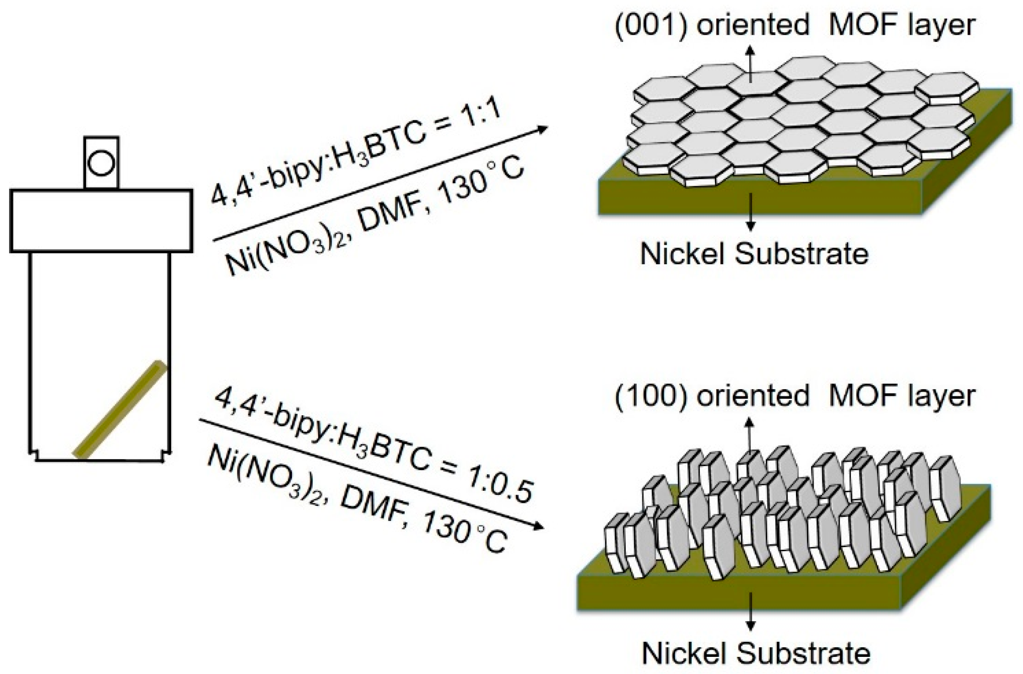
The (100) crystal plan oriented [Ni(HBTC)(4,4′-bipy)] MOF membrane was prepared based on in situ solvothermal reaction. After being pressed under the pressure of 20 MPa, the Nickel foam was cut into rectangle pieces in the size of 25 × 5 mm as substrates. The substrates were immersed in 25% hydrochloric acid solution for 30 min in order to remove the Nickel oxide on the surface. The substrates were then washed with excess of deionized water and ethanol. After that, 1 equivalent Ni(NO3)2·6H2O, 0.5 equivalent H3BTC and 1 equivalent 4,4′-bipyridine were added into 10 mL DMF with one Nickel foam substrate in a 20 mL Teflon-lined autoclave. The Nickel substrate was leaned against the inner wall of Teflon liner. The autoclaves were then placed in an oven preheated to 130 °C for 36 h. After the autoclave was cooled to room temperature naturally, membranes were then taken out and washed with 30 mL fresh DMF. The membrane was placed with bottom up and dried at room temperature for 12 h for other characterization. The (001) crystal plan oriented [Ni(HBTC)(4,4′-bipy)] membrane was similarly prepared to that of the (100) crystal plan oriented [Ni(HBTC)(4,4′-bipy)] membrane, except the amount of H3BTC changed to 1 equivalent.
2.4. Characterization
Gas adsorption isotherms were recorded by a volumetric method using a Micromeritics ASAP2020 surface area and pore analyzer (Micromeritics Instrument Corporation, Norcross, GA, USA). The SEM images were recorded with a Hitachi SU3500 microscopy (Hitachi, Ibaraki, Japan) at 15 kV. PXRD data were collected in a Rigaku Smartlab3 (Rigaku Corporation, Tokyo, Japan) by copper-sealed tube (
λ = 1.54178 Å) at room temperature. Simulation of the PXRD spectra was carried out by the single-crystal data and diffraction crystal module of the Mercury program available free of charge via
http://www.ccdc.cam.ac.uk/mercury/.
3. Results and Discussion
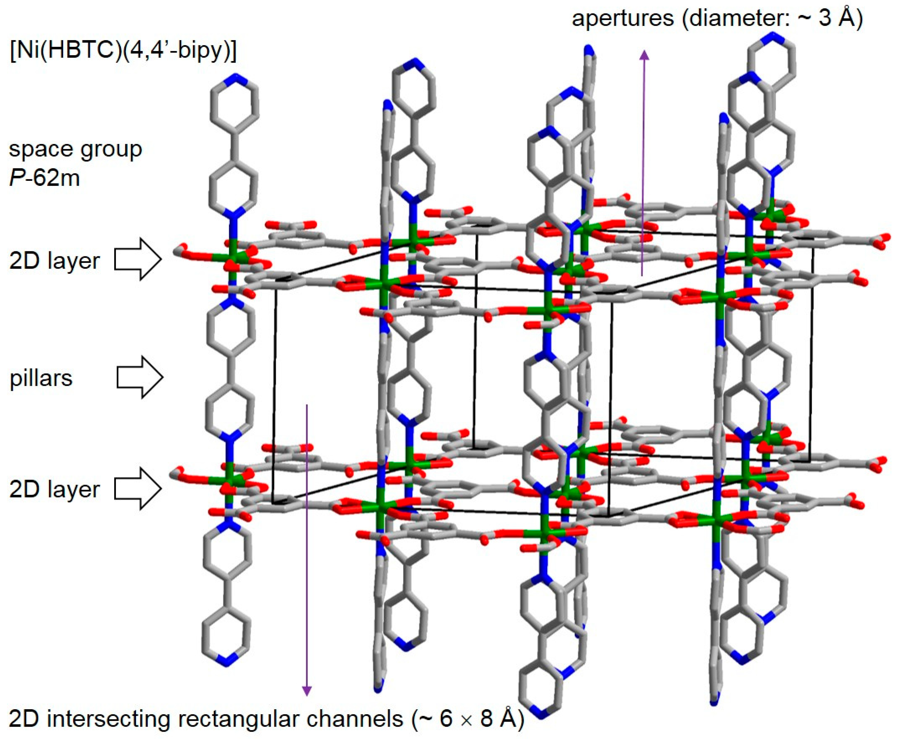
The MOF [Ni(HBTC)(4,4′-bipy)] has a three-dimensional (3D) porous pillared-layer framework structure (
Figure 1). And, the 2D layers consist of Nickel ions interconnected by partially deprotonated H
3BTC ligands, the 4,4′-bipy ligands serve as the pillars between these layers. The MOF crystalizes in the space group
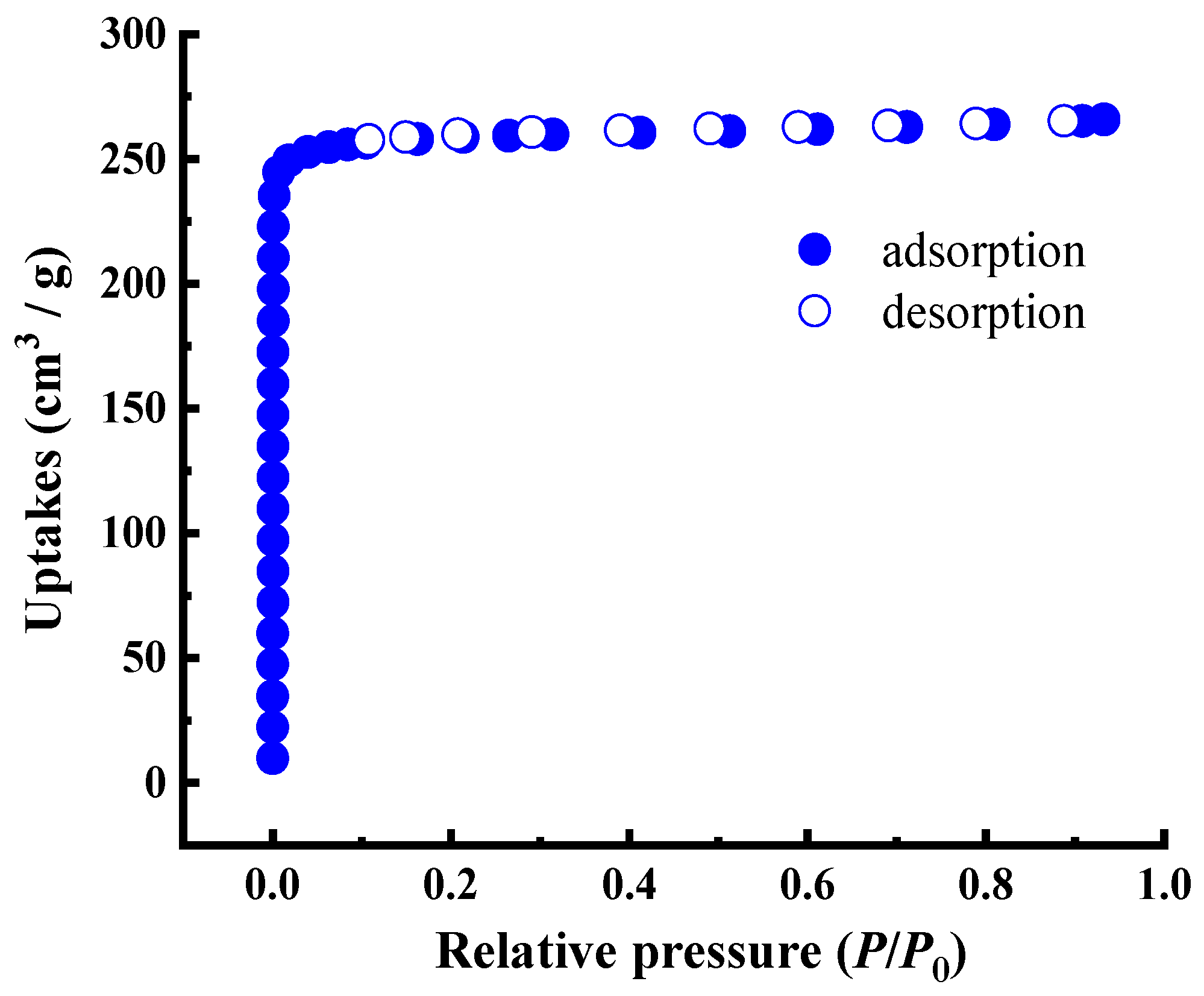
P-62m (No. 189). There are 2D intersecting rectangular channels in sizes of ~6 × 8 Å between the 2D layers, and small apertures with a diameter of ~3 Å on the 2D layers. Before the fabrication of MOF membrane for [Ni(HBTC)(4,4′-bipy)], MOF powder was synthesized according to the reported synthesis method [
28]. The phase purity of the synthesized MOF powder was verified by PXRD measurement, and the permanent porosity of the MOF powder was confirmed by N
2 adsorption at 77 K. As shown in
Figure 2, the PXRD pattern of the synthesized [Ni(HBTC)(4,4′-bipy)] powder matches well with the simulated pattern from its single crystal structure data, indicating the successful preparation of the MOF with high purity. Before the N
2 adsorption isotherm measurement, the MOF powder was guest exchanged with methanol, and then activated in high vacuum at 65 °C for 12 h. The N
2 adsorption isotherm (
Figure 3) was a typical type I isotherm for microporous materials with an uptake of 266 cm
3 g
−1 at
P/
P0 = 0.93 and the Brunauer–Emmett–Teller (BET) surface area of 760 m
2 g
−1, which are in consistence with the results of the original report (N
2 adsorption saturation uptake: 290 cm
3 g
−1).
After the [Ni(HBTC)(4,4′-bipy)] powder was obtained, it is necessary to explore the experimental conditions for fabricating a membrane of this MOF. At the beginning, the macroporous
α-AL
2O
3 substrates (diameter: 18 mm, thickness: 2 mm), which are widely used [
30], were used to grow the MOF membrane through in situ growth in the reaction for the MOF powder. However, after the reaction no crystals were found on both sides of the substrate, although MOF powder was formed in the solvent. At that time, it came to us that maybe the MOF membrane could be prepared by the method of secondary growth of seeded substrate. Unfortunately, only relatively large crystals (40 μm) were obtained no matter how the experimental conditions (reaction temperatures, solvents, concentrations, and ratio of ligand and metal salt) changed. Finally, the results showed that those conditions are not suitable for seeding the
α-AL
2O
3 substrate because the crystals precipitated in common solvents very fast.
After considering the presence of Nickel ions in the MOF, then we tried to fabricate the [Ni(HBTC)(4,4′-bipy)] membrane on the Nickel foam based porous substrate. The substrate as prepared by the following procedure: six layers of Nickel foams (
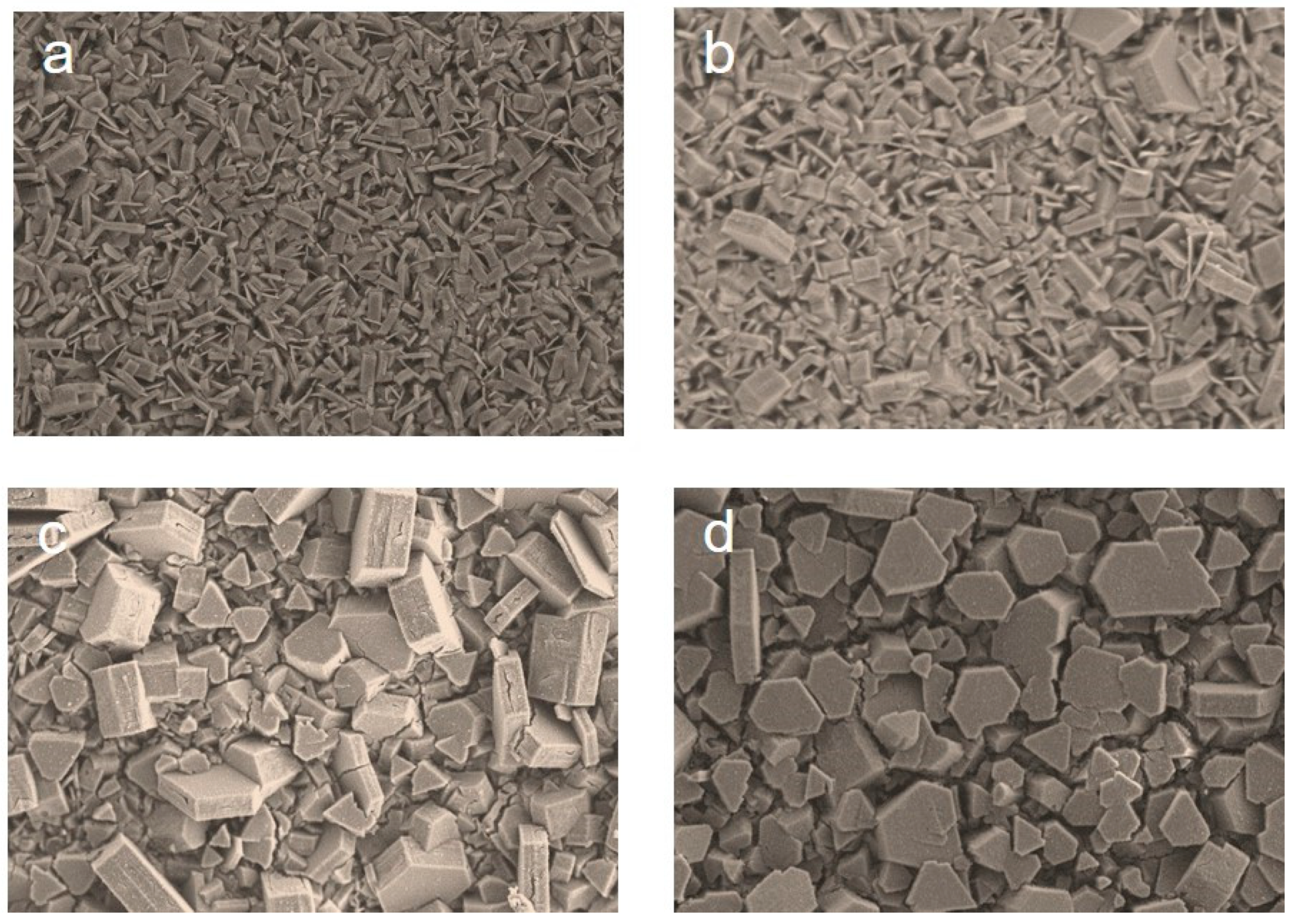
Figure S1) were folded into one, and it was then subject to hydraulic pressing at 20 MPa for 1 min to improve the mechanical strength of the Nickel foam. The substrate which was pressure treated is still porous, and the pores size are 50~100 μm (
Figure 4a). The substrate was washed by excess of deionized water and ethanol to remove any contaminants on its surface before it was used for the in situ fabrication of MOF membrane. However, again, no crystals were found on both sides of the substrate after the reaction completed, although MOF powder was formed in the solvent. It came to us that the Nickel oxide on the surface of Nickel foam substrate might affect the nucleation and growth of the Ni-based MOF on the substrate. Thus, the substrate was treated with 25% hydrochloric acid solution for 40 min to remove the Nickel oxide, and the reaction for growing the MOF crystals was carried out with the acid treated Nickel foam substrate. As shown in
Figure 4c, continuous and well intergrown crystal layer with thickness about 30 μm was formed on the surface of substrate. PXRD pattern of crystal layer well matched that of the MOF [Ni(HBTC)(4,4′-bipy)] (
Figure 4d), confirming the successful preparation of the MOF membrane on the Nickel foam substrate. Experiments with different reaction durations were also carried out. As shown in
Figure S2, the MOF layer obtained by a 12 h reaction was not quite continuous, but the MOF crystals of the membrane were compact after the reaction lasted for 36 h. Interestingly, a membrane with different microstructure was obtained when the amount of H
3BTC was changed from 0.5 into 1 equivalent with respected to 4,4′-bipy. As shown in
Figure 4e,f, the MOF layer was also continuous and the crystals were [Ni(HBTC)(4,4′-bipy)] according to the PXRD pattern. The orientations of MOF crystals in the two membranes obtained are much different. For the latter one, most the hexagon crystal faces of hexagonal prismatic crystals are exposed on the top side of membrane. In contrast, in the former one, the rectangle crystal faces of the hexagonal prismatic crystals are exposed on the top side of membrane.
Indeed, PXRD patterns also suggested the MOF crystals in the two membranes are highly preferentially oriented. As shown in
Figure 4d, the diffraction intensity ratio of the peak at 18.31° corresponding to the (300) crystal planes to the peak at 7.73° corresponding to the (001) crystal planes is 9.78, evidently larger than that in the simulated pattern (0.15), indicating the membrane is (300) crystal plane oriented. For the other membrane as shown in
Figure 4f, the diffraction intensity ratio of the peak at 7.73° corresponding to the (001) crystal planes to the peak at 18.31° corresponding to the (300) crystal planes is 9.25, larger than that in the simulated pattern (6.52), indicating the membrane is (001) crystal plane oriented. Accordingly, the peak at 15.80° corresponding to the (002) crystal planes and the peak at 23.77° corresponding to the (003) crystal planes are also stronger than the other peaks.
In fact, these results obtained from the PXRD patterns can be also extrapolated from the morphology of the MOF layers as shown in the SEM images. As it crystalizes in the space group
P-62
m (No. 189) of the hexagonal crystal system, the crystals of [Ni(HBTC)(4,4′-bipy)] are hexagonal prism shaped. As shown in
Figure 4b, the top and bottom hexagonal crystal faces of a hexagonal prism shaped crystal are corresponding to the (001) crystal planes, and the rectangle crystal faces are corresponding to the (100), (1–10), and (010) crystal planes, respectively. For the former membrane, the hexagonal crystal faces are perpendicular to the top surface of the substrate, leaving the rectangle crystal faces exposed on the top. In such an orientation, diffraction from (100), (1–10) and (010) crystal planes can be preferentially recorded. However, due to systematic absence, diffraction peaks for those crystal planes are not observed. But a strong peak corresponding to the (300) crystal planes is observed, which is also related to the (100) crystal planes, verifying the effect of preferential orientation for the MOF crystals. For the other membrane, the hexagonal crystal faces corresponding to the (001) crystal planes are exposed on the top, resulting in the observation of the strong diffraction peaks from (001), (002) and (003) crystal planes. In short, the SEM images and PXRD patterns are matched and clarify the highly preferential orientations of the MOF membranes.
In common, it is not easy to control the orientations of MOF membranes. However, in our case, the orientations of the [Ni(HBTC)(4,4′-bipy)] membrane was simply controlled by the amount of ligand H
3BTC added into the reaction. When the amount of H
3BTC was 0.5 equivalent with respect to ligand 4,4′-bipy, rectangle faces of the [Ni(HBTC)(4,4′-bipy)] crystals are exposed on the membrane surface, and hexagonal crystal faces are exposed on the top of membrane when the amount of H
3BTC was changed to 1 equivalent with respect to ligand 4,4′-bipy. Experiments with more varied amounts of H
3BTC (0.3, 0.6, 0.9 and 1.2 equivalent) were also carried out. As shown in
Figure 5, the orientations of membrane gradually changed from (100) to (001) with increasing of H
3BTC amount. When 0.3 equivalent H
3BTC was used, on the top of obtained membrane, the exposed crystal faces are almost all the rectangle crystal faces (
Figure 5a). With the increased amount of H
3BTC, more and more hexagonal crystal faces could be observed on the top of the membrane (
Figure 4c and
Figure 5b). The exposed hexagonal crystal faces were dominantly found on the top when the amount of H
3BTC was 1.2 equivalent. Additionally, we found that MOF crystals were bigger when more H
3BTC was used, probably because the increase of H
3BTC increases the acidity of the reaction mixture and suppresses the coordination of the metal ion and the ligands, leading to slower nucleation and growth of the crystals. Until now, the reason for why the [Ni(HBTC)(4,4′-bipy)] membranes with two orientations can be fabricated by simply changing the ratio of the ligands is still not clear. It is believed that the amount of H
3BTC introduced has an effect on the acidity of reaction system and further changes the process of nucleation and growth of the MOF crystals.
Experiments were also performed to check if other Ni(II)-based MOFs could be similarly grown on the Nickel foam substrate. It was reported that a 2D layer structure MOF [Ni(HBTC)(DMF)
2] could be synthesized from a reaction very similar to that of [Ni(HBTC)(4,4′-bipy)], only except the ligand 4,4′-bipy was not added into the reaction system [
28]. It can be simply regarded that [Ni(HBTC)(DMF)
2] is a structure obtained from [Ni(HBTC)(4,4′-bipy)] by replacing the one coordinated 4,4′-bipy with two coordinated DMF molecules between the natural [Ni(HBTC)] layers. A reaction for [Ni(HBTC)(DMF)
2] was carried out with the Nickel foam substrate introduced, and the result showed that no continuous MOF layer was formed on the substrate, where only sparse crystals were observed (
Figure S3). It is interesting that the recipe for [Ni(HBTC)(4,4′-bipy)] membrane could not be applied to the growth of another MOF membrane, [Ni(HBTC)(DMF)
2], although the syntheses and structures of the two MOFs are very similar. The result indicates that the 4,4′-bipy ligand not only serves as building block for the 3D structure of [Ni(HBTC)(DMF)
2], but also plays an important role in anchoring the MOF crystals on the substrate at the stage of crystal nucleation and in the final formation of a well-intergrown membrane. It is believed that the coordination interaction between the Nickel substrate and the 4,4′-bipy is related to such a bonding effect. In addition, it was found that the continuous [Ni(HBTC)(4,4′-bipy)] membranes could not be obtained with Copper foam substrates, indicating that the presence of homologous metal element Nickel in both the MOF and the substrate is also necessary for the membrane fabrication.
Gas permeability was also tested for the (001) crystal plan oriented [Ni(HBTC)(4,4′-bipy)] membrane. The MOF membrane was treated by two steps before permeation test: dipping in methanol for 2 days and then being activated under high vacuum at 65 °C for 12 h. Unfortunately, the MOF layer cracked after fully activation, as confirmed by SEM images (
Figure S4). Some works have shown that activation and regeneration methods of MOF membranes are important to avoid cracking [
31,
32]. However, in our case, the membranes always cracked although many other activation methods were tried. Research on how to overcome the cracking of the MOF membrane is underway in our group.


