Article

Phononic Crystal Plate with Hollow Pillars Actively Controlled by Fluid Filling

1
Institut d’Electronique, de Microélectronique et de Nanotechnologie, UMR CNRS 8520, Université de Lille 1, Villeneuve d’Ascq 59650, France
2
School of Aerospace Engineering and Applied Mechanics, Tongji University, 100 Zhangwu Road, Shanghai 200092, China
*
Authors to whom correspondence should be addressed.
Crystals 2016, 6(6), 64; https://doi.org/10.3390/cryst6060064
Submission received: 6 April 2016 / Revised: 14 May 2016 / Accepted: 19 May 2016 / Published: 24 May 2016
(This article belongs to the Special Issue Phononic Crystals)

Abstract

:
We investigate theoretically the properties of phononic crystal plates with hollow pillars. Such crystals can exhibit confined whispering gallery modes around the hollow parts of the pillars whose localization can be increased by separating the pillar from the plate by a full cylinder. We discuss the behaviors of these modes and their potential applications in guiding and filtering. Filling the hollow parts with a fluid gives rise to new localized modes, which depend on the physical properties and height of the fluid. Thus, these modes can be actively controlled for the purpose of multichannel multiplexing. In particular, one can obtain localized modes associated with the compressional vibrations of the fluid along its height. They can be used for the purpose of sensing the acoustic properties of the fluid or their variations with temperature.

Graphical Abstract

1. Introduction

In the past two decades, the development of phononic crystals (PnCs) [1,2,3,4], which consist of periodic arrangement of inclusions embedded in a matrix, has brought novel properties for controlling acoustic/elastic waves, such as waveguiding [5,6], filtering [7,8], sensing [9,10], and design of lens for sound focusing [11,12,13]. Due to their periodic structure, PnCs can exhibit acoustic band gaps that result from either Bragg scattering or local resonances. In particular, both types of gaps can be found in phononic crystal plates constituted by a periodic array of pillars deposited on a thin plate, provided the geometrical parameters are chosen appropriately [14,15,16]. Subsequently, these structures have received increasing attention. For instance, Oudich et al. [17] studied a stubbed plate with one-layer soft stub and two-layer composite stub and found a low resonant acoustic band gap. Assouar and Oudich [18] reported that, by using double-sided stubbed phononic plates, locally resonant band gaps could be enlarged. Coffy et al. [19] designed a strip consisting of periodic pillars deposited on a tailed beam, enabling the generation of an ultra-wide band gap resulting from both Bragg scattering and local resonance. Midtvedt et al. [20] considered a graphene membrane that is deposited on top of a square lattice of cylindrical pillars to exhibit coupled localized modes with nonlinear dynamics. Using Brillouin light scattering experiments, Graczykowski et al. [21] showed significant changes in the hypersonic phonon propagation due to the presence of local resonances in phononic crystal made of a square lattice of holes and pillars in/on silicon membrane. Very recently, Jin et al. [22] explored confined whispering-gallery modes (WGMs) by considering hollow pillars on a thin plate. The confined WGMs with high quality factors allow for manipulating the acoustic waves for guiding and filtering applications in both Bragg and low frequency band gaps. Additionally, hollow pillars on a plate give rise to the possibility of filling the hollow parts with a liquid, which creates new modes for the manipulation of acoustic waves, in particular allowing their active control by changing the height of the fluid or its temperature. Jin et al. [23] and Popa et al. [24] reported that the acoustic properties of PnCs and acoustic metamaterials could be actively tuned by piezoelectric structures. Wang et al. [25] used nonlinear pre-deformation to tune the band gap with local resonant structures. With infiltrated liquids in the hollow pillars, another actively controlled phononic crystal can be proposed since, for instance, the mass density and acoustic velocity of the liquids change with temperature.
In this paper, we study the dispersion and transmission of localized modes in a phononic crystal plate with hollow pillars. In the first part, we present the results for WGMs in the hollow pillar structures along the symmetry directions of the first irreducible Brillouin zone. The second part is devoted to the effects of filling the hollow parts with a liquid. This will affect the frequencies and quality factors of the WGMs depending on the physical properties and height of the fluids, and this can be used for an active control of these modes or the design of a multichannel wavelength multiplexer. Besides that, the structure also supports very confined modes in the fluid, corresponding in particular to the compressional modes along the height of the fluid. The localization of such modes in the broad Bragg band gap allows for the design of a phononic sensor, which is sensitive to the acoustic properties of the fluid, in particular to their variations in temperature. Section 2 contains the results and discussions of our calculations for the hollow and liquid-filled pillars, respectively. Some conclusions are drawn in Section 3.

2. Results and Discussion

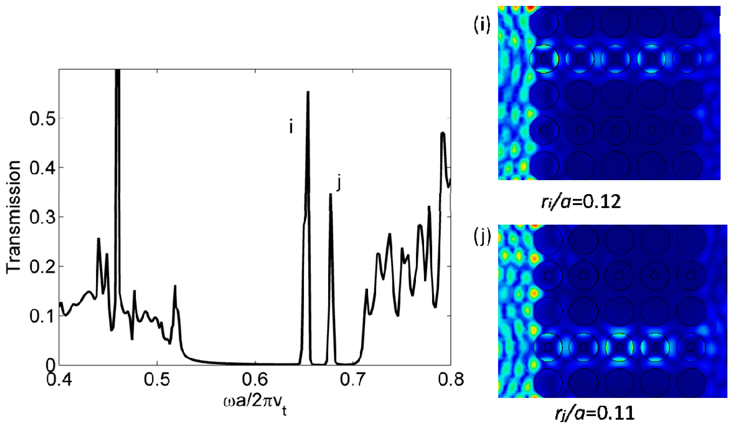
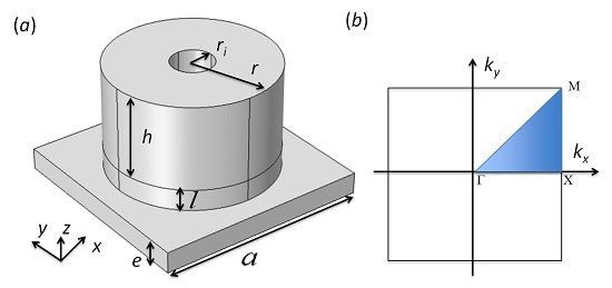
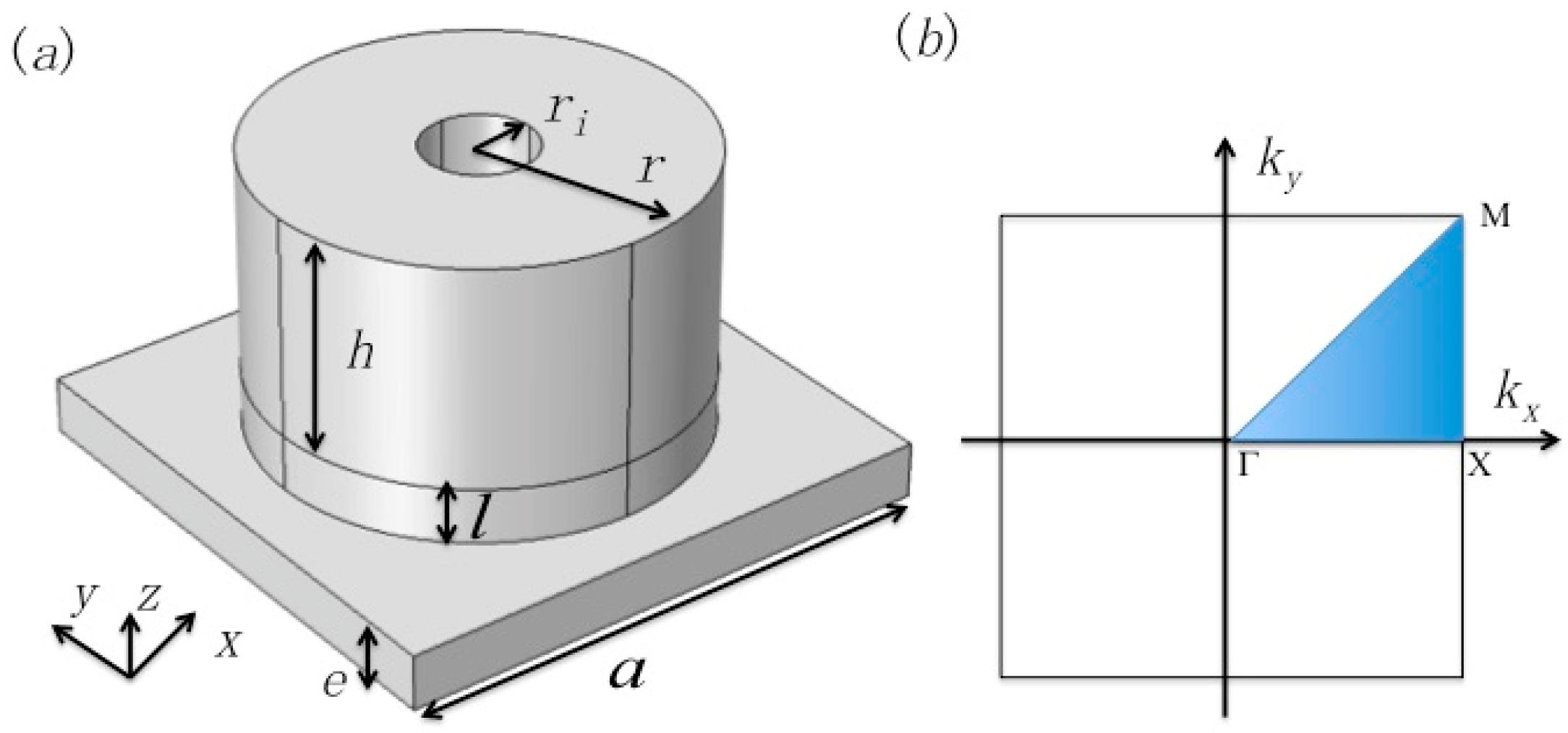
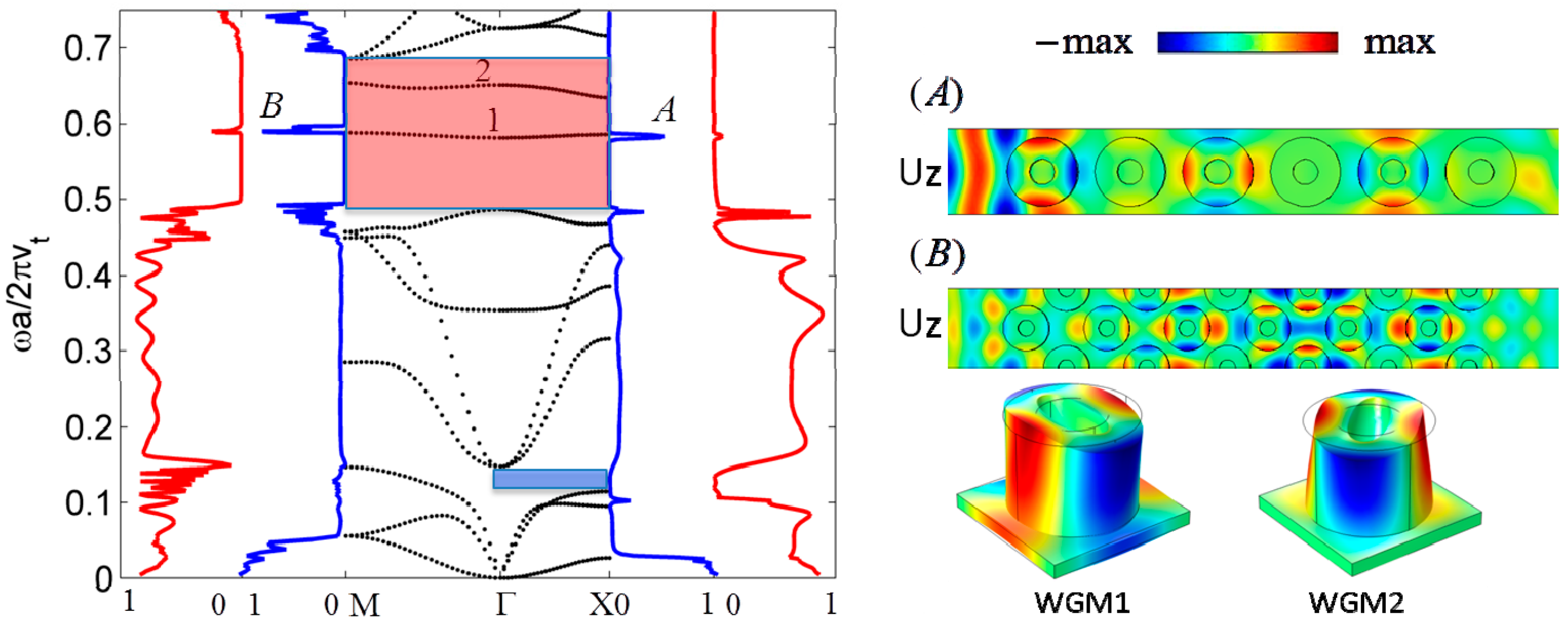
2.1. Whispering-Gallery Modes

A PnC of a square lattice with a periodicity a in the (x, y) plane is considered that consists of a periodic array of hollow pillars deposited on a thin plate (Figure 1a). A full cylinder separates the hollow part from the plate in order to increase the confinement of the studied modes. The scheme in Figure 1a shows the geometrical parameters, namely the lattice constant a, the thickness of the plate e, the height of confinement l, the height of the hollow pillar h, its inner radius ri and outer radius r. The entire structure is made of cubic silicon, with the elastic constants C11 = 166 GPa, C12 = 64 GPa, C44 = 79.6 GPa, and the mass density being ρ = 2330 kg·m−3. The crystallographic axis [100] and [010] have been chosen respectively parallel to the phononic crystal axis x and y. In the (x, y) plane, periodic boundary conditions are applied on each side of the unit cell. Dispersion and transmission curves are calculated by the finite element code COMSOL Multiphysics® (COMSOL Inc., Stockholm, Sweden) and presented as a function of the reduced frequency wa/2πvt, where vt = Sqrt (0.5*(C11C12)/ρ) is the transverse velocity of sound in silicon along the [110] direction in the (001) plane.
With an appropriate choice of the geometrical parameters (r/a = 0.4, h/a = 0.45, e/a = 0.1), the native PnC with full pillars deposited on a thin plate can exhibit two absolute band gaps, one at the Bragg frequency regime and the other at low frequency regime [14]. By introducing an inner hole in the pillar, two new branches of WGMs with quadrupolar shape occur in the dispersion curves that do not appear in the native PnC; their fields are localized in the upper part of the pillars around the hollow. The quality factor of the WGMs can be further increased by adding a full cylinder between the hollow pillar and the plate, so that the elastic energy is better confined in the hollow pillar part [22]. This new structure was first studied in [22]. In this section, we give some additional results with respect to the conclusions of [22].
In Figure 2, we present more detailed properties of the WGMs. In the left panel, the black dotted lines are dispersion curves calculated along the ΓX and ΓM directions of the first Brillouin zone with geometric parameters ri/a = 0.145, r/a = 0.4, h/a = 0.45, e/a = 0.1, l/a = 0.2. With this set of parameters, the Bragg and low frequency band gaps still appear along ΓX direction while only a Bragg band gap remains along the ΓM direction. In the Bragg band gap, two branches of WGMs occur, marked as branch ‘1’ and ‘2’. Two transmission spectra along each direction are associated with two different incident waves, namely the fundamental anti-symmetric A0 Lamb (blue curve) and the symmetric S0 (red curve) Lamb waves. Although some mode conversion can occur at the exit of PnC, the transmitted wave keeps essentially its original character. Only WGM1 gives rise to a narrow transmitted pass band in both the ΓX and ΓM directions, more significantly with anti-symmetric Lamb wave excitation, marked as peak ‘A’ and ‘B’. In the right panel of Figure 2, we show the displacement fields of the dominant Uz component (displacement along z-axis) for peak ‘A’ and ‘B’. The excitation inside the PnC is symmetric with respect to an xz plane, perpendicular to the pillars and parallel to the propagation direction. This is in accordance with the symmetry of the incident wave (either A0 or S0) with respect to such a plane. In contrast, to obtain a transmission at the frequency of WGM2, it would be necessary to have an incident wave which has an antisymmetric profile with respect to this plane, which means −/+ force in the unit cell along the y-direction. To explain the higher transmission of WGM1 with the A0 rather than S0 incident wave, it should be noticed that the x and y components of its displacement field are mainly localized in the upper part of the pillar, around the hollow part, while the z component extends down to the bottom of the pillar and is therefore sensitive to a vertical motion in the membrane. However, in some other frequency ranges such as [0.2; 0.4], the transmission is much higher with S0 rather than A0 excitation.
Figure 3 (left panel) presents the evolution of the two WGMs as a function of the inner radius of the hollow pillar. Both WGM frequencies decrease when increasing the inner radius. Indeed, it is noteworthy that a higher value of the average radius <r> = (r + ri) 2 of the shell around the hollow increases the acoustic path along the perimeter 2π<r> of the cylinder. As a result, when ri/a = 0.145 (resp. 0.35), the WGM ‘1’ and ‘2’ fall in the middle of the Bragg (resp. low frequency) gap [22]. We also calculate the corresponding quality factor for the WGM 1, Q = ff, where f is the central frequency of the pass band and Δf is the full width at half maximum of the transmission peak. The right panel of Figure 3 shows a significant increase in the quality factor when increasing the reduced height l/a of the pillar basis. For l/a = 0.35, the quality factor is Q = 280, which is more than 10 times the value obtained without the additional cylinder, paving the way to a high resolved narrow pass band device for filtering applications [22].
The WGMs with high quality factors are applied to different kinds of multiplexers, based on monochannel or multichannel waveguides or cavity. In Figure 4, we show a multichannel waveguide consisting of waveguide i with inner radius ri/a = 0.12 and waveguide j with inner radius rj/a = 0.11. The transmission peaks for waveguide i and j are located at reduced frequency 0.654 and 0.678, respectively. In addition, an efficient subwavelength waveguide is also demonstrated, as the WGMs can be tuned in the low frequency band gap [22].

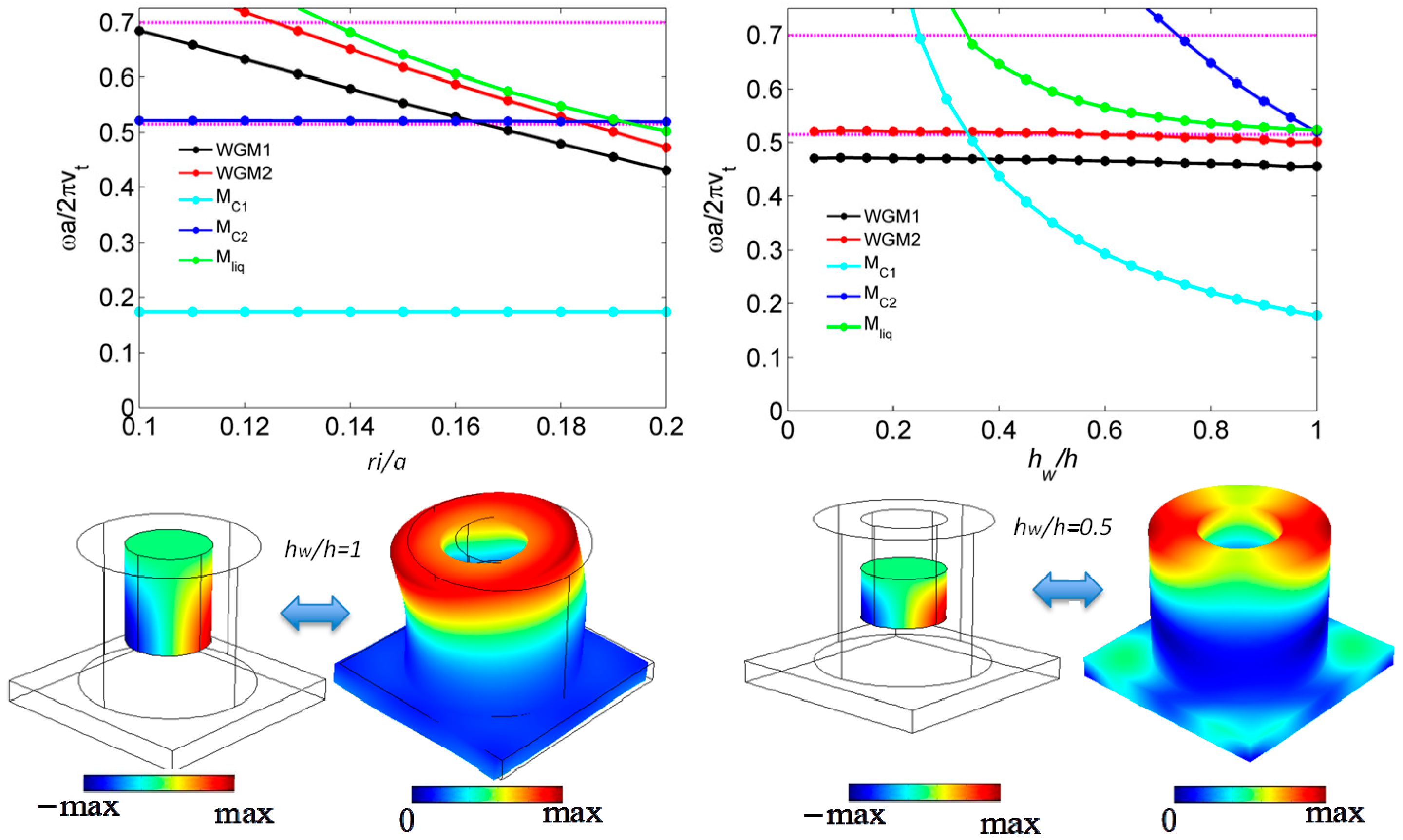
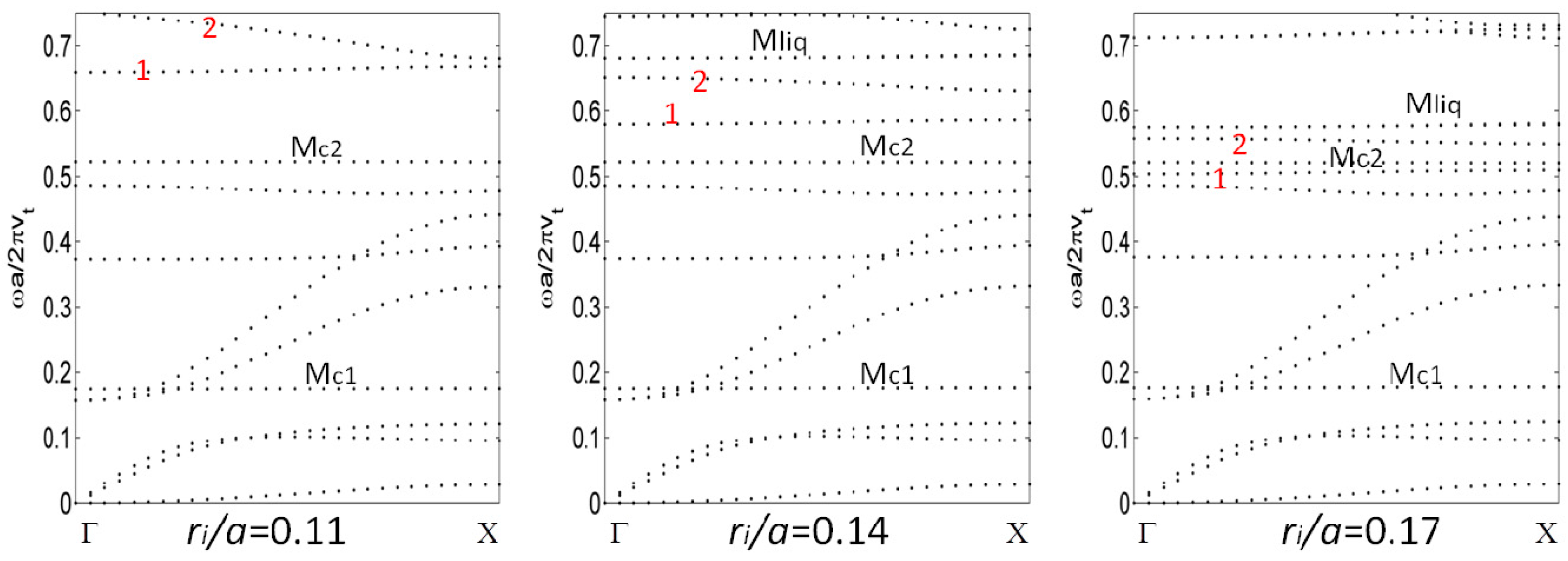
2.2. Active Control of the WGMs and New Localized Modes by Filling the Hollows with a Liquid

The objective of this section is to discuss how the filling of the holes with a liquid can affect or tune the WGMs, and, more interestingly, gives rise to the occurrence of new localized modes in the band gap that are much sensitive to the presence of the fluid. The latter can be tuned with the physical and geometrical properties of the fluid, in particular its height. To avoid capillary or surface tension effects, it would be more adapted to work with holes of sub-millimeter size in the MHz regime. However, it should be pointed out that the filling of a few tens of nm size holes in hypersonic PnC has been performed by micro-fluid ejection technique and their phonon dispersion curves measured by Brillouin light scattering experiments (see, for instance, References [26,27]).
In Figure 5, we show the dispersion curves of the phononic crystal when the holes are filled with water for a few values of the inner radius ri. For water, the mass density is ρ = 998 kg·m−3 and speed of sound is c = 1490 ms−1. Let us start with the inner radius ri/a = 0.17. The modes labeled 1 and 2 are the quadrupolar WGMs discussed in the previous section. However, the filling of the holes with water has the effect of giving rise to two new sets of localized modes in the band gap. One set, labeled Mc1 and Mc2, correspond to compressional vibrations inside the liquid column almost independently of the solid; they will be discussed in detail in Section 2.3. The other set called Mliq is a doubly degenerate new mode that is essentially associated to the presence of the liquid and appears in the band gap under some conditions on the geometrical parameters. The strongest vibration of this mode occurs in the liquid where the displacement field is one order of magnitude higher than in the solid part. When decreasing the inner radius ri/a of the pillars from 0.17 to 0.11 (Figure 5), the WGM1,2, as well as Mliq, see their frequency increasing and going outside the band gap, while the frequencies of Mc1 and Mc2 remain unchanged because they are dictated by the height of the fluid.
As a complementary view, we show, in the upper panel of Figure 6, how the localized modes, namely WGM1,2, Mc1,2 and Mliq, behave when changing either the inner radius of the hollow pillars or the height hw of the fluid filling the hollow part of the pillar of total height h. In the upper-left panel, one can see, in accordance with Figure 5, that with an increasing inner radius, WGM1,2 and Mliq decrease to lower frequencies, passing out of the Bragg band gap of the full PnC (h/a = 0.45, r/a = 0.4, l/a = 0). On the other hand, Mc2 is practically insensitive to the inner radii, as the compressional mode in the liquid is only related to the height of the liquid (see discussion in Section 2.3.). In the upper-right panel of Figure 6, we present the evolution of those localized modes as a function of the height hw of water filling the pillar of total height h when the inner radius is ri/a = 0.19. The liquid compressional modes Mc1,2 are very sensitive to hw, whereas the Mliq decreases through the Bragg band gap when hw/h increases from 0.3 to 1. The latter mode can be then a good candidate to be tuned gradually by changing the height of water. The vibration of this mode is presented in the lower panel of Figure 6, both in the solid and liquid part. One can see that the elastic and acoustic fields are mainly oriented along the diagonal direction of the square lattice. The vibration in the solid is mostly localized at the top of the pillar although there are still some displacements left in the plate. In the liquid part, the pressure field behaves like a dipolar motion, with −max and +max along the same diagonal direction.
Finally, let us notice that the quadrupolar WGM1,2 can also be tuned by the height of water but with very small shifts. It should be noticed that WGM1,2 are essentially originating from the solid pillars in the absence of the liquid. Even with filling the holes, their acoustic energy remains mostly localized in the solid region surrounding the hollow part, although the vibration in the liquid becomes not negligible. This penetration of the wave into the liquid should soften the mode and decrease its frequency, although the effect remains small with water. In Section 2.4 (Figure 10), we shall see that filling the holes with mercury, which has a much higher impedance than water, and therefore is comparable to silicon, will affect the frequency of WGMs more strongly.

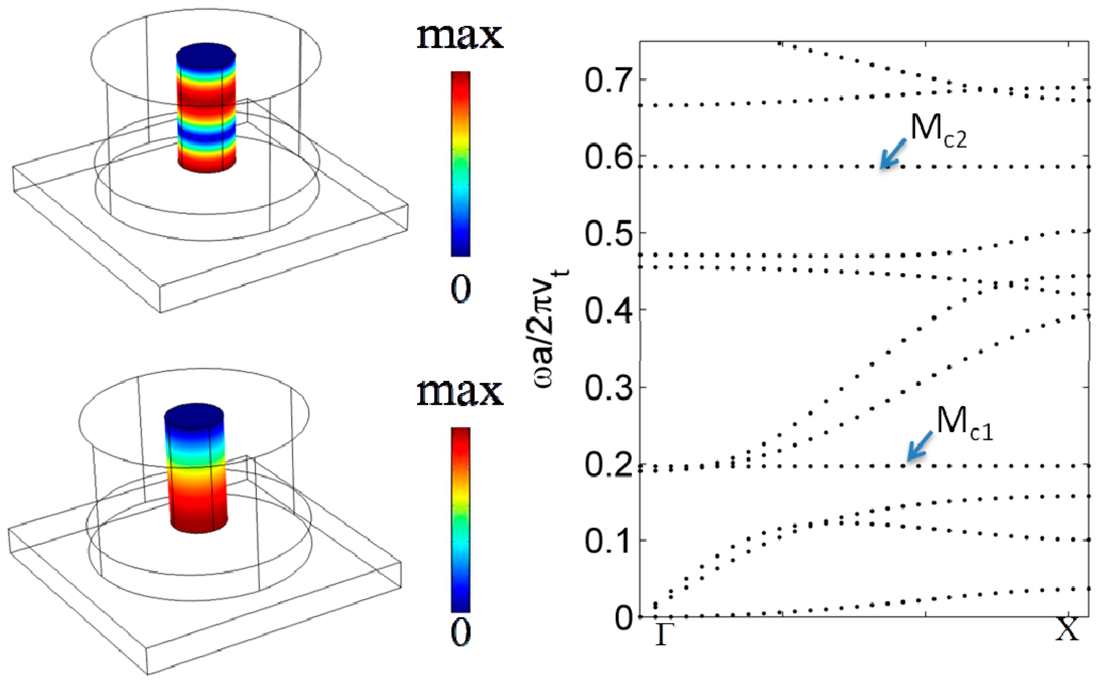
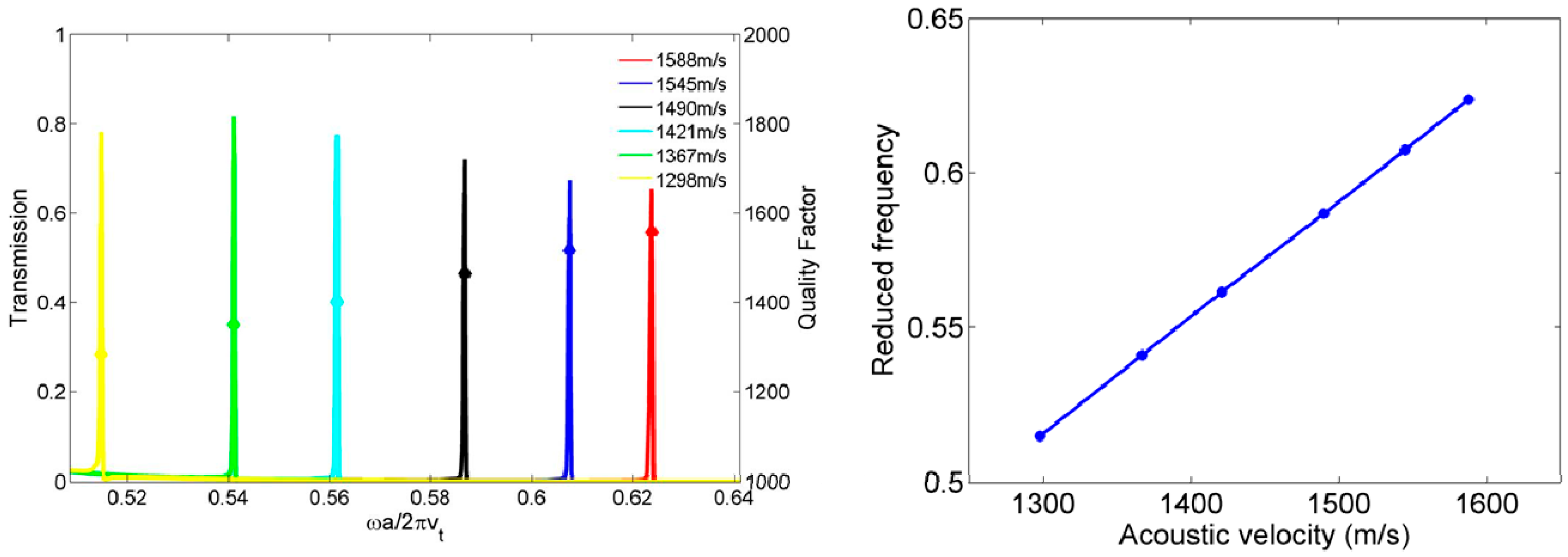
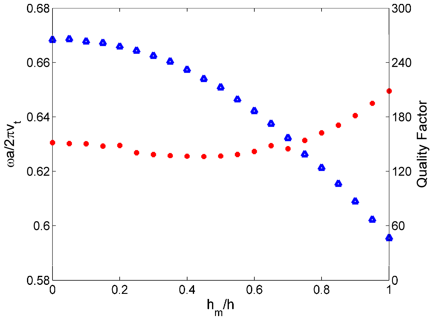
2.3. Compressional Modes along the Height of the Liquid

In this section, we discuss the modes called Mc in the previous section, which are associated to vertical motion inside the fluid. Due to the high impedance mismatch between most of the liquids and a hard solid, these modes are mainly localized inside the fluid. We give two illustrations about the sensitivity of these modes to the physical properties of the liquid and the variation of its parameters as a function of temperature.
First, it should be noticed that if the holes are filled with a liquid such as water that has a much smaller impedance than silicon, the frequency of the compressional modes are given with a very good precision by the resonance frequencies of a tube of height hliq with rigid lateral boundaries, rigid bottom boundary and a free upper boundary. The expressions of the frequencies are then fn = (2n + 1)c/4 hliq, where n is the resonance number (0, 1, 2, 3, ...), and c is the speed of sound in the fluid; this means that the height can accommodate stationary waves at λ/4, 3λ/4,…
In Figure 7, the hollow pillar filled with water has geometric parameters as h/a = 0.4, r/a = 0.39, ri/a = 0.1, hw/h = 1, and l/a = 0.1. The first and the second compressional liquid frequencies are fc1 = 0.197 and fc2 = 0.587, corresponding to a wavelength λc1/h = 4 and λc2/h = 4/3, respectively, as shown clearly in the pressure distributions in the left panel. The set of geometric parameters are chosen to move the WGMs to higher frequencies outside of the Bragg band gap. From the right panel, the first compressional liquid mode is at the edge of the low frequency band gap while the second one is in the middle of the Bragg band gap. We focus on the second compressional liquid mode, as the Bragg band gap is broader and has more potential in the applications.
In a first example, we consider a set of mixtures of water and 1-propanol at different molar ratio x. We use the mass density and speed of sound at different molar ratio x as shown in Table 1 from References [9,10].
The Mc2 in the Bragg band gap is isolated, allowing a phononic sensor application to sense the probed parameters on a sufficiently broad frequency range. The efficiency of the phononic sensor is detected by changing the physical properties of the filled liquid in the hollow pillar. Six kinds of liquids are employed to test the efficiency [9,10]. Figure 8 left panel presents the evolution of the Mc2 induced transmission peaks as a function of the acoustic velocity. It is observed that the transmission peaks are very sensitive to the acoustic velocity of the infiltrated liquid, with high quality factors Q = ff larger than 1000. Figure 8 (right panel) shows the relationship between the frequency of transmission peak and the corresponding acoustic velocity. In order to qualify the sensitivity, a common measurement is to calculate the slope of the lines in the right panel, named sensitivity S, as S = Δf/Δc, where Δf is the difference of the reduced frequencies of two infiltrated liquids and Δc = (cliqicliqj)/vt is the difference of the reduced velocities of two infiltrated liquids by dividing the transverse velocity of silicon vt to have a dimensionless quantity. The average of S is 1.761, with a deviation 2.53% for the minimum and 0.87% for the maximum.
Furthermore, it is well known that the mass density and acoustic velocity of water will change if we vary the temperature of the liquid. We take the mass density and the acoustic velocity of water at different temperatures as shown in Table 2 from reference [7]. The temperature affects the elastic constant of silicon one order of magnitude lower than for the liquid [28]. Thus, we assume that the temperature of the solid background of the PnC is kept fixed at the room temperature and the thermal property of the water in the hollow pillars is isolated from the solid background. The geometric parameters of the PnC are h/a = 0.4, r/a = 0.39, ri/a = 0.1, hw/h = 1, l/a = 0.1. By tuning the temperature of water from 0 °C to 70 °C, the frequency of the Mc2 increases with its corresponding quality factor decreasing, as shown in Figure 9. In the range of [0 °C; 50 °C], the frequency moves significantly in the step of 10 °C. Therefore, tuning the temperature of the infiltrated liquid is another way to actively control the Mc2 induced transmission peak.

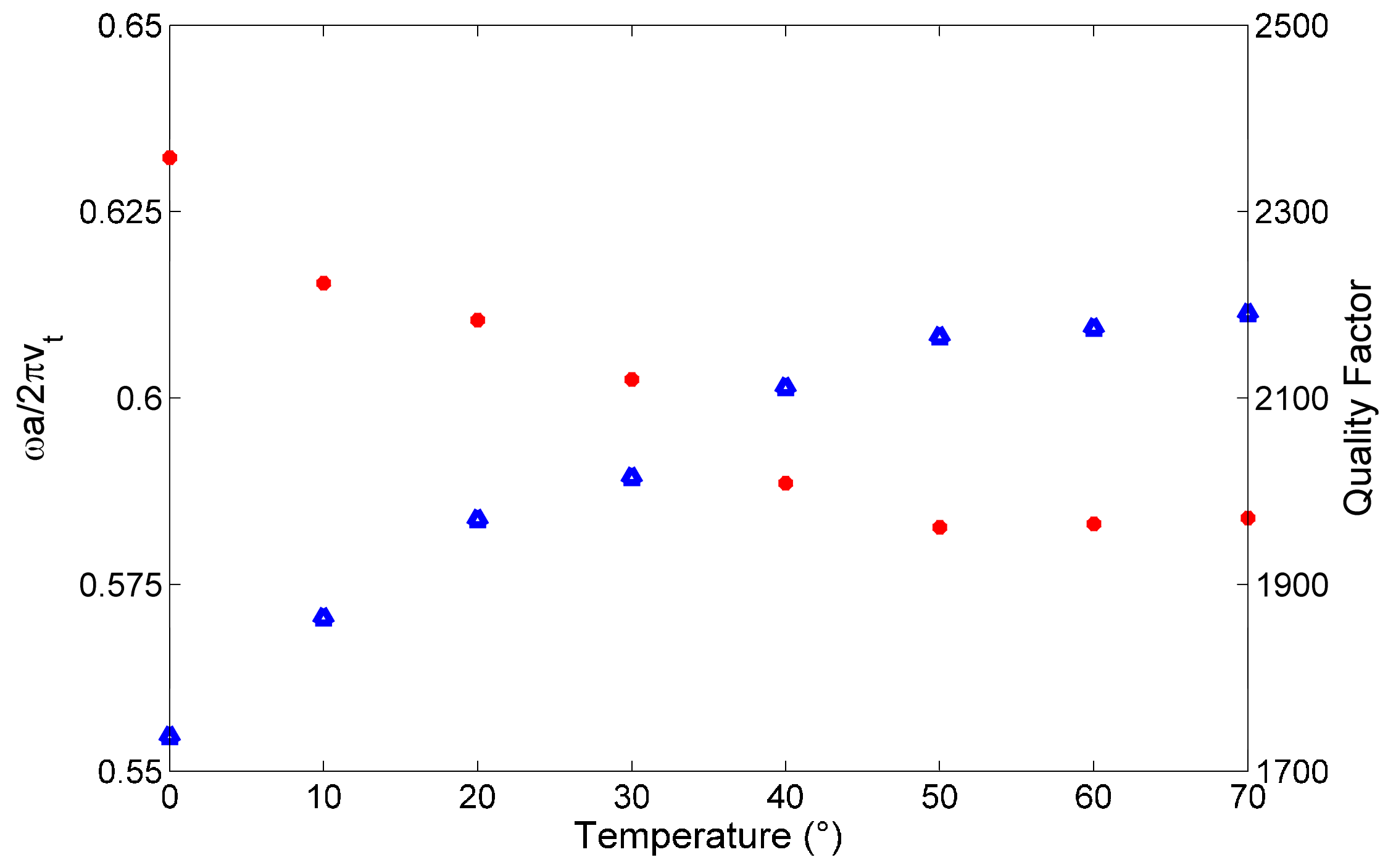
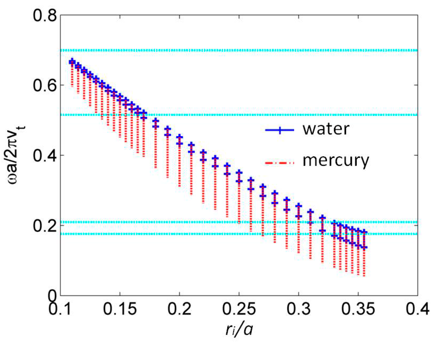
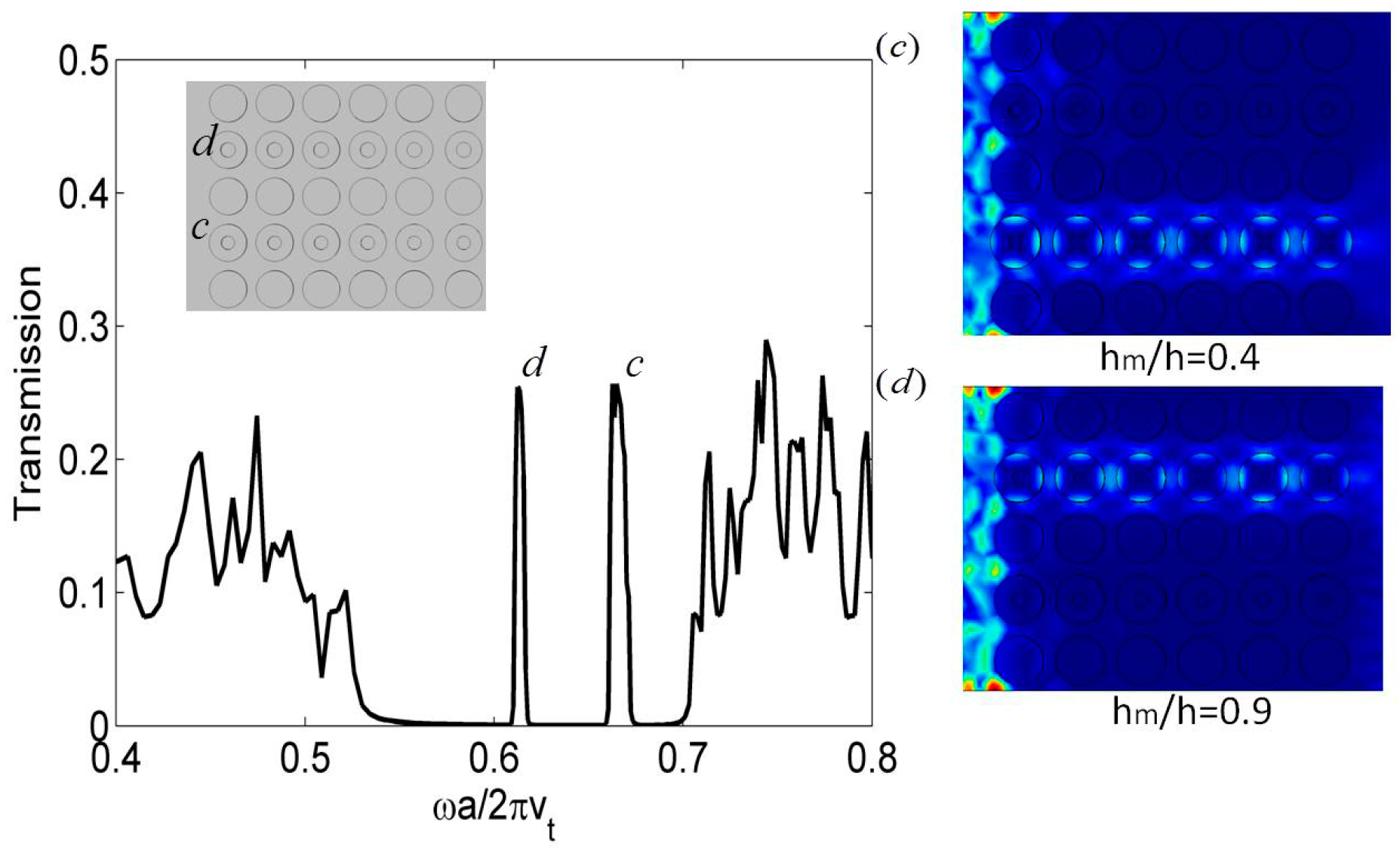
2.4. Influence of Filling the Holes with Mercury on Whispering Gallery Modes

The common liquids have very small impedance comparing to silicon. However, there is one liquid in nature, namely mercury, whose impedance is even a bit higher than silicon. We also studied the behavior of WGM1 as a function of the inner radius when the holes are filled with mercury of different heights and compared the results with the case of water. Figure 10 presents that, at each inner radius, the upper end of the vertical bar is the frequency of WGM1 when the inner hole is empty, and the lower end is the frequency when the inner hole is entirely filled with liquid; the red dotted bars are for mercury and, as a matter of comparison, the blue dotted bars are for water. For mercury, the mass density is ρ = 13,600 kg·m−3 and speed of sound is c = 1490 ms−1. The upper frequency range limited by two horizontal cyan lines is the Bragg band gap of background full PnCs (h/a = 0.45, r/a = 0.4, l/a = 0), and the lower one is the low frequency band gap. The tunable frequency range of the WGM1 increases when the inner radius becomes larger, as the corresponding filling ratio φ = Ahole/Apillar increases, where Ahole, Apillar are the area of inner hole and whole pillar, respectively. For a given inner radius, the tunable frequency range for mercury is wider than that for water due to the fact that the impedance Zm = ρc of mercury is much larger than the impedance of water, even larger than that of silicon. In the Bragg band gap, mercury plays a more important role in actively controlling the WGM1.
Due to the fact that the property of the liquid is easier to control than that of the solid, we can realize an active control of the PnC’s functionalities, such as waveguiding or sensing. In Figure 11, we present the evolution of the WGM1 frequency and its corresponding quality factor by changing the height of the fluid in the holes. To be specific, by increasing the height of mercury, the frequency of WGM1 moves to lower values, plotted in blue triangle dots, especially in the range hm/h > 0.4. The red dots show that the quality factor of WGM1 does not change too much within the range hm/h = [0; 0.6] and increases from 140 at hm/h = 0.6 to 210 at hm/h = 1. The regime where the WGM1 changes significantly with respect to hm is still located in the Bragg band gap, allowing for the realization of an actively tuned multichannel wavelength multiplexer.
To illustrate the latter application, we consider a 5 × 6 super cell with periodic conditions applied in the y-axis and Perfect Matched Layer applied in the direction of propagation x, as shown the inset of Figure 12 left panel. The PnC contains two separated waveguides c and d, which are constituted by two rows of the same hollow pillars filled with mercury at hmc/h = 0.4 and hmd/h = 0.9, respectively. The geometric parameters for the two waveguides are h/a = 0.45, r/a = 0.4, l/a = 0.2, ri/a = 0.11. The background full cylinders have parameters as h/a = 0.45, r/a = 0.4, l/a = 0. The transmission is detected by exciting the anti-symmetric Lamb wave in front of the PnC. In the left panel, two narrow pass bands c and d appear in the Bragg band gap at reduced frequency 0.66 and 0.61, respectively. The higher height of mercury significantly shifts the transmission frequency to a lower value inside the band gap. The corresponding displacement field distributions in the solid silicon are presented in the right panel of Figure 12, showing a multichannel wavelength multiplexer behavior.

3. Conclusions

We investigated the vibrational properties of hollow pillars filled with liquids deposited on a thin homogeneous plate. Whispering Gallery Modes (WGMs) circulating around the upper boundary of the hollow pillar give rise to new branches in the dispersion curves that do not appear in native full PnC. We studied the dispersion and transmission excited by both anti-symmetric and symmetric Lamb waves along the ΓX and ΓM directions and found that the WGM1 can be well excited by an anti-symmetric Lamb wave and generate a narrow pass band. Then, we filled the inner holes with liquids and figured out that the frequency of WGM1 decreases while the corresponding quality factor increases with the height of liquid. We discussed a functionality to design an active multichannel wavelength multiplexer by tuning the height of liquids in the waveguides. In addition, a simple theoretical model is provided to explain the compressional liquid modes in the hollow pillars. These modes are isolated in the broad Bragg band gap with high quality factors larger than 1000 and applied to design a phononic sensor to sense a mixture of water and 1-propanol at different molar ratio x with a high efficiency. By increasing the temperatures in the infiltrated liquid, the frequency of the second compressional mode moves to higher frequencies, realizing an active control. Finally, we found that the liquid-filling of the holes give rise to a new type of localized mode Mliq in the band gap with a dipolar shape displacement field, which can be a good candidate for tuning as a function of the liquid height. The phononic crystal plate with fluid filled in the hollow pillars can be a good candidate for wireless communication and sensing applications with the possibility of active control.

Acknowledgments

This work was supported by the “Agence Nationale de la Recherche (ANR)” and the“Delegation Generale de l’Armement (DGA)” under the project Metactif, Grant No. 443 ANR-11-ASTR-015. Yabin Jin acknowledges a scholarship provided by China Scholarship Council No. 201406260170.

Author Contributions

Jin Y. designed and performed the simulations; Djafari Rouhani B. supervised the research; Jin Y., Pennec Y. and Djafari Rouhani B. prepared the manuscript; Jin Y., Pennec Y., Pan Y. and Djafari Rouhani B. discussed the results and reviewed the manuscript.

Conflicts of Interest

The authors declare no conflict of interest.

References

  1. Kushwaha, M.S.; Halevi, P.; Dobrzynski, L.; Djafari-Rouhani, B. Acoustic band structure of periodic elastic composites. Phys. Rev. Lett. 1993, 71, 2022–2025. [Google Scholar] [CrossRef] [PubMed]
  2. Sigalas, M.; Economou, E.N. Band structure of elastic waves in two dimensional systems. Solid State Commun. 1993, 86, 141–143. [Google Scholar] [CrossRef]
  3. Pennec, Y.; Vasseur, J.O.; Djafari-Rouhani, B.; Dobrzynski, L.; Deymier, P.A. Two-Dimensional phononic crystals: Examples and applications. Surf. Sci. Rep. 2010, 65, 229–291. [Google Scholar] [CrossRef]
  4. Hussein, M.I.; Leamy, M.J.; Ruzzene, M. Dynamics of phononic materials and structures: Historical origins, recent progress and future outlook. Appl. Mech. Rev. 2014, 66, 040802. [Google Scholar] [CrossRef]
  5. Khelif, A.; Choujaa, A.; Benchabane, S.; Djafari-Rouhani, B.; Laude, V. Guiding and bending of acoustic waves in highly confined phononic crystal waveguides. Appl. Phys. Lett. 2004, 84, 4400. [Google Scholar] [CrossRef]
  6. Sun, J.H.; Wu, T.T. Propagation of acoustic waves in Phononic-Crystal plates and waveguides using a finite-difference Time-Domain method. Phys. Rev. B 2007, 76, 104304. [Google Scholar] [CrossRef]
  7. Rostami-Dogolsara, B.; Moravvej-Farshi, M.K.; Nazari, F. Acoustic add-drop filters based on phononic crystal ring resonants. Phys. Rev. B 2016, 93, 014304. [Google Scholar] [CrossRef]
  8. Pennec, Y.; Djafari-Rouhani, B.; Vasseur, J.O.; Khelif, A.; Deymier, P.A. Tunable filtering and demultiplexing in phononic crystals with hollow cylinders. Phys. Rev. E 2004, 69, 046608. [Google Scholar] [CrossRef] [PubMed]
  9. Lucklum, R.; Li, J. Phononic crystals for liquid sensor applications. Acoustic band structure of periodic elastic composites. Meas. Sci. Technol. 2009, 20, 124014. [Google Scholar] [CrossRef]
  10. Amoudache, S.; Pennec, Y.; Djafari-Rouhani, B.; Khater, A.; Lucklum, R.; Tigrine, R. Simultaneous sensing of light and sound velocities of fluids in a two-dimensional phoXonic crystal with defects. J. Appl. Phys. 2014, 115, 134503. [Google Scholar] [CrossRef]
  11. Yang, S.; Page, J.H.; Liu, Z.; Cowan, M.L.; Chan, C.T.; Sheng, P. Focusing of sound in a 3D phononic crystal. Phys. Rev. Lett. 2004, 93, 024301. [Google Scholar] [CrossRef] [PubMed]
  12. Jin, Y.; Torrent, D.; Pennec, Y.; Pan, Y.; Djafari-Rouhani, B. Simultaneous control of the S0 and A0 Lamb modes by graded phononic crystal plates. J. Appl. Phys. 2015, 117, 244904. [Google Scholar] [CrossRef]
  13. Jin, Y.; Torrent, D.; Pennec, Y.; Pan, Y.; Djafari-Rouhani, B. Gradient index devices for the full control of elastic waves in plates. Sci. Rep. 2016, 6, 24437. [Google Scholar] [CrossRef] [PubMed]
  14. Pennec, Y.; Djafari-Rouhani, B.; Larabi, H.; Vasseur, J.O.; Hladky-Henion, A.C. Low-Frequency gaps in a phononic crystal constituted of cylindrical dots deposited on a thin homogeneous plate. Phys. Rev. B. 2008, 78, 104105. [Google Scholar] [CrossRef]
  15. Wu, T.T.; Huang, Z.G.; Tsai, T.C.; Wu, T.C. Evidence of complete band gap and resonances in a plate with periodic stubbed surface. Appl. Phys. Lett. 2008, 93, 111902. [Google Scholar] [CrossRef]
  16. Pennec, Y.; Djafari-Rouhani, B.; Larabi, H.; Akjouj, A.; Gillet, J.N.; Vasseur, J.O.; Thabet, G. Phonon transport and waveguiding in a phononic crystal made up of cylindrical dots on a thin homogeneous plate. Phys. Rev. B 2009, 80, 144302. [Google Scholar] [CrossRef]
  17. Oudich, M.; Li, Y.; Assouar, M.B.; Hou, Z. A sonic band gap based on the locally resonant phononic plates with stubs. New J. Phys. 2010, 12, 083049. [Google Scholar] [CrossRef]
  18. Assouar, M.B.; Oudich, M. Enlargement of a locally resonant sonic band gap by using double-Sides stubbed phononic plates. Appl. Phys. Lett. 2012, 100, 123506. [Google Scholar] [CrossRef]
  19. Coffy, E.; Lavergne, T.; Addouche, M.; Euphrasie, S.; Vairac, P.; Khelif, A. Ultra-Wide acoustic band gaps in pillar-Based phononic crystal strips. J. Appl. Phys. 2015, 118, 214902. [Google Scholar] [CrossRef]
  20. Midtvedt, D.; Isacsson, A.; Croy, A. Nonlinear phononics using atomically thin membrances. Nat. Commun. 2014, 5, 4838. [Google Scholar] [CrossRef] [PubMed]
  21. Graczykowshi, B.; Sledzinska, M.; Alzina, F.; Gomis-Bresco, J.; Reparaz, J.S.; Wagner, M.R.; Sotomayor Torres, C.M. Phonon dispersion in hypersonic two-dimensional phononic crystal membranes. Phys. Rev. B 2015, 91, 075414. [Google Scholar] [CrossRef]
  22. Jin, Y.; Fernez, N.; Pennec, Y.; Bonello, B.; Moiseyenko, R.P.; Hemon, S.; Pan, Y.; Djafari-Rouhani, B. Tunable waveguide and cavity in a phononic crystal plate by controlling whispering-Gallery modes in hollow pillars. Phys. Rev. B 2016, 93, 054109. [Google Scholar] [CrossRef]
  23. Jin, Y.; Bonello, B.; Pan, Y. Acoustic metamaterials with piezoelectric resonant structures. J. Phys. D Appl. Phys. 2014, 47, 245301. [Google Scholar] [CrossRef]
  24. Popa, B.T.; Cummer, S.A. Non-Reciprocal and highly nonlinear active acoustic metamaterials. Nat. Commun. 2014, 5, 3398. [Google Scholar] [CrossRef] [PubMed]
  25. Wang, P.; Casadei, F.; Shan, S.; Weaver, J.C.; Bertoldi, K. Harnessing buckling to design tunable locally resonant acoustic metamaterials. Phys. Rev. Lett. 2014, 113, 014301. [Google Scholar] [CrossRef] [PubMed]
  26. Sato, A.; Pennec, Y.; Shingne, N.; Thurn-Albrecht, T.; Knoll, W.; Steinhart, M.; Djafari-Rouhani, B.; Fytas, G. Tuning and switching the hypersonic phononic properties of elastic impedance contrast nanocomposites. ACS Nano 2010, 4, 3471. [Google Scholar] [CrossRef] [PubMed]
  27. Demirci, U.; Montesano, G. Single cell epitaxy by acoustic picolitre droplets. Lab Chip 2007, 7, 1139. [Google Scholar] [CrossRef] [PubMed]
  28. Tilli, M.; Motooka, T.; Airaksinen, V.; Franssila, S.; Paulasto-Krockel, M.; Lindroos, V. Handbook of Silicon Based MEMs Materials and Technologies, 2nd ed.; William Andrew: London, UK, 2015. [Google Scholar]
Figure 1. (a) schematic view of the PnC unit cell in the square array consisting of hollow pillars deposited on a thin homogeneous plate with an additional cylinder of height l at the basis to improve the confinement of the modes in the hollow pillars. a is the lattice constant, e is the thickness of plate, h is the height of hollow pillar, ri and r are the inner and outer radius of the hollow pillar, respectively; (b) the irreducible first Brillouin zone of the square lattice.
Crystals 06 00064 g001
Figure 2. (Left panel): Dispersion curves of the confined hollow pillars on a thin silicon plate in the ΓX and ΓM directions of the first irreducible Brillouin zone in the reduced frequency range [0; 0.75]. On each side of the dispersion curves, we give the corresponding transmission spectra in blue and red respectively for which the incident wave is either anti-symmetric A0 or symmetric S0. The Bragg and low frequency band gaps are marked as red and blue rectangular hatched regions, respectively. The geometric parameters are chosen as ri/a = 0.145, r/a = 0.4, h/a = 0.45, e/a = 0.1, l/a = 0.2; (Right panel): Uz component of the displacement fields with the anti-symmetric A0 Lamb wave excitation at transmission peak A along the ΓX direction and peak B along the ΓM direction; Uz component of the displacement fields of WGM1 and WGM2 at Γ point.
Crystals 06 00064 g002
Figure 3. (Left panel): the frequency evolution of the WGM 1 and 2 as a function of the inner radius of the hollow pillar. The upper frequency range limited by two horizontal cyan lines is the Bragg band gap of background full PnCs (h/a = 0.45, r/a = 0.4, l/a = 0) and the lower one is the low frequency band gap. (Right panel): The quality factor of the WGM 1 grows when increasing the confinement height l/a, ri/a = 0.145.
Crystals 06 00064 g003
Figure 4. The multichannel wavelength multiplexer: (Left panel): Transmission spectrum of the antisymmetric Lamb wave when the inner radius inside waveguides i and j are ri/a = 0.12 and rj/a = 0.11; (Right panel): Displacement field distributions at the frequency of the two narrow pass bands i and j. The geometric parameters of the multiplexer are h/a = 0.45, r/a = 0.4, l/a = 0.2.
Crystals 06 00064 g004
Figure 5. Dispersion curves of the hollow pillars on a thin silicon plate in the ΓX direction with different inner radii (left) ri/a = 0.11, (middle) ri/a = 0.14, (right) ri/a = 0.17. The other geometric parameters are h/a = 0.45, r/a = 0.4, l/a = 0.2.
Crystals 06 00064 g005
Figure 6. (Upper-left panel): evolution of WGM1 (black dotted line), WGM2 (red dotted line), Mc1 (cyan dotted line), Mc2 (blue dotted line), Mliq (green dotted line) as a function of inner radius when the hollow pillars are fully filled with water (hw/h = 1). The two horizontal pink dotted lines are the limits of Bragg band gap of the full PnC; (Upper-right panel): evolution of WGM1 (black dotted line), WGM2 (red dotted line), Mc1 (cyan dotted line), Mc2 (blue dotted line), Mliq (green dotted line) as a function of the height of filling water hw/h when the inner radius is ri/a = 0.19. (Lower panel): representation of the acoustic (pressure) and elastic (displacement) field of the mode Mliq respectively in the fluid and solid part for hw/h = 1 (left) and hw/h = 0.5 (right) when ri/a = 0.19. The other geometric parameters are h/a = 0.45, r/a = 0.4, l/a = 0.2.
Crystals 06 00064 g006
Figure 7. (Left panel): 3D-schematic view of the pressure fields in water of the Mc1 (left-lower) and Mc2 (left-upper) compressional modes; (Right panel): Dispersion curves of the PnC with geometric parameters h/a = 0.4, r/a = 0.39, ri/a = 0.1, hw/h = 1, l/a = 0.1 along the ΓX direction.
Crystals 06 00064 g007
Figure 8. (Left panel): Evolution of the second liquid compressional mode induced transmission peak (lines, corresponding to the left y-axis) and quality factor (dots, corresponding to the right y-axis) as a function of the acoustic velocity of filled liquid. The geometric parameters are h/a = 0.4, r/a = 0.39, ri/a = 0.1, hliq/h = 1, l/a = 0.1. (Right panel): The frequency of transmission peak corresponds to the acoustic velocity of different fluids.
Crystals 06 00064 g008
Figure 9. Varied frequencies (blue triangular dots) and corresponding quality factors (red circle dots) of the second liquid compressional mode by tuning the temperature of water in the holes. The geometric parameters are h/a = 0.4, r/a = 0.39, ri/a = 0.1, hw/h = 1, l/a = 0.1.
Crystals 06 00064 g009
Figure 10. Varied range of WGM 1 frequency when the holes are respectively empty or fully filled with the liquid: water (blue dotted lines) and mercury (red dotted lines), corresponding to different inner radii. The other geometric parameters are h/a = 0.45, r/a = 0.4, l/a = 0.2. The upper frequency range limited by two horizontal cyan lines is the Bragg band gap of background full PnCs (h/a = 0.45, r/a = 0.4, l/a = 0) and the lower one is the low frequency band gap.
Crystals 06 00064 g010
Figure 11. The evolutions of the WGM 1 frequency (blue triangle dots) and its corresponding quality factor (red circle dots) as a function of the filled mercury height. The geometric parameters are h/a = 0.45, r/a = 0.4, l/a = 0.2, ri/a = 0.11.
Crystals 06 00064 g011
Figure 12. The multichannel wavelength multiplexer. (Left panel): Transmission spectrum of the antisymmetric Lamb wave when the filled mercury heights inside waveguide c and d are hmc/h = 0.4 and hmd/h = 0.9; (Right panel): Displacement field distributions at the frequency of the two narrow pass bands c and d. The geometric parameters of the multiplexer are h/a = 0.45, r/a = 0.4, l/a = 0.2, ri/a = 0.11.
Crystals 06 00064 g012
Table 1. Density and speed of sound of a mixture of water and 1-propanol at different molar ratio x.
Molar Ratio xDensity (kg·m−3)Speed of Sound (ms−1)
0 (water)9981490
0.0219901545
0.0569741588
0.2309081421
0.3478811367
0.5968411298
Table 2. Mass density and acoustic velocity of water at various temperatures.
T (°C)Mass Density (kg·m−3)Speed of Sound (ms−1)
09991405
109991447
209981482
309971497
409921529
509861547
609831550
709771554

