1. Introduction
The geometrical conception of atoms and ions has offered a straightforward approach for the physical modelling of hetero-polar crystals. In particular, the model of spherical ions having a constant radius has been widely disseminated [
1,
2], and numerous applications have been noted in diverse fields, such as high-
Tc superconductors [
3], multiferroic compounds [
4] or the modelling of technical devices, like high-
k field-effect transistors [
5], to mention only a few examples. The approach assumes that ions of a chemical element and specific valence attain the same spherical volume in distinct crystalline compounds AB, such that the interatomic distance
dAB between the nearest neighbors is determined by the addition of radii
rA +
rB.
The concept celebrated its greatest success in applying it to rock salt- or sphalerite-structured compounds, where the ions occupy lattice sites of point groups
m3
m (
Oh) or
43
m (
Td). Here, consistent ionic radii could be derived that are exhibited in all of those crystals with only little variations [
6]. It was the concept’s tempting promise that one geometric parameter would be conserved in all crystal surroundings, establishing a crystal-chemical conservation law. As it turned out, however, the respective ionic radii had to be split into different values according to bonding geometry, coordination number,
etc., in order to arrive at sufficiently accurate interatomic distances. The extensive analysis of some hundred oxide and fluoride compounds led Shannon and Prewitt (1969) and Shannon (1976) to a set of ionic radii from the majority of relevant ions that still represent the state-of-the-art data [
7,
8]. Although these tables allowed for an accurate modelling of bond distances for the compounds from which they derive, many bond distances could only be predicted with little accuracy, in particular, when crystals with highly polarizable ions or complex crystallographic structures were considered.
The question arises whether more accurate results can be obtained when more general shapes than spheres would be used. In fact, since the crystal potential is superimposed to the spherical potential of the ion’s nucleus, there is no reason to stipulate a spherical shape for ions in crystal lattices. In the first attempt, it might be assumed that ions have to be modelled by ellipsoids instead of spheres, which should yield interatomic distances of improved accuracy for ions on polar lattice sites [
9,
10]. Koch and Fischer equally emphasized that the ellipsoidal modelling would appear more appropriate in certain crystal lattices with particularly convincing results to be expected for intermetallic compounds, like MgCu
2 [
2]. Later, Birkholz and Rudert fully exploited the formalism to transition metal disulfides crystallizing in the pyrite structure. They showed that the sulfur ion in the MS
2 series, with M = Mn, Fe, Co, Ni, Cu, can consistently be described by a rotational ellipsoid with varying main axes
r|| and r
⊥ [
11]. The significance of this more complex consideration of bonding geometry for the
Tc maximum in solid solution of superconducting pyrite-type di-selenides and di-tellurides has recently been demonstrated by Guo and co-workers [
12,
13]. In order to study more crystals with respect to the applicability of the approach, the complete set of pyrite-type compounds MX
2 with monovalent chalcogenide ions X
− will be investigated in this work.
2. Motivation of Ellipsoidally Shaped Ions in Crystals
The starting point of the approach is the Neumann principle, according to which any observable quantity of a quantum mechanical system has to obey the same symmetry as the system itself [
14]. Here, ionic multi-electron atoms located on crystal lattice sites obeying one of the 32 crystallographic point groups (PG) will be associated with the system, while their electron densities and bond distances will be regarded as observables. The notion of the crystalline field will be followed in this work, as already introduced by Bethe [
15]. However, the emphasis will not be on the splitting of atomic terms, but on the splitting of orbital energies and the consequences for their spatial extension.
It will be assumed that the electronic levels of ions in crystals can be described within the orbital approximation [
16]. Furthermore, the crystalline lattice will be supposed to be static, and dynamic effects will be neglected. It will be assumed for the charge density of ions that a possible asphericity is only related to their valence electrons, while inner shell electrons are fully accounted for by a spherical density function, ρ(
r,θ,φ) = ρ
core(
r) + ρ
val(
r,θ,φ). The approach shares common aspects with techniques for the determination of electron densities (ED) from X-ray diffraction [
17,
18,
19]. The question of ionic shape, however, is substantially easier than a full ED determination, since it only seeks the course of the outermost iso-contour surface of the electron density instead of its entire distribution in the unit cell.
Use will be made of the self-consistent Hartree–Fock formalism, since it allows writing the electron density of a many electron system as a sum of squares of basis functions. The latter are accounted for by
![Crystals 04 00390 i002]()
, with principal quantum number
n [
20].
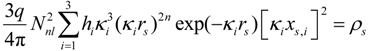
Rnl stands for the radial function that determines the ions spatial extension and
κnl is the contraction-expansion parameter having the dimensionality of an inverse length. Strictly speaking,
Rnl does not only depend on the radial coordinate
r, but on its product with
κnl having
Rnl =
Rnl(
κnlr). The parameter
κ is usually associated with an effective nuclear charge
Zeff via
κ =
Zeffmq2/(2πε
0ћ2n) in order to account for screening (
m electron mass,
q elementary charge, ε
0 permittivity of vacuum). Moreover,
κ is related to the bonding energy of the electronic level via
En = −
κ2ћ2/(8
m) [
20].
The geometric significance of
κ lies in the fact that it determines the radial extension until to which the particular orbital extends in space. In general, the radial part
Rnl of electronic state
nl is given by the sum over a small number of basis functions of the form:
where
Nnl is a normalization factor depending only on
n and
l. The determination of the set of
κ parameters and their relative weights in the sum over all Equation (1) terms is the central task of the Hartree–Fock procedure [
16,
21,
22,
23,
24]. Since this work is only concerned with the outermost course of the electron density of an ion, it will be assumed that considering one single term suffices to describe the ED at large distances from the nucleus. This will be the term with the smallest
κ value.
The basis functions are assumed to be affected by the crystal field, which may lead to a splitting of levels with the same
l that were considered degenerate in case of the free ion [
14]. The angular parts
43
m of the symmetry-adapted basis functions derive from basis functions spanning the irreducible representations (irrep) of the full rotation group
Dl, which are the spherical harmonics:
In this expression, the index µ is used instead of
m in order to numerate the different irreps [
24]. The set of
![Crystals 04 00390 i004]()
is unequivocally defined for each of the 32 PG; for a tabulation, see [
25]. The symmetry-adapted basis functions
![Crystals 04 00390 i005]()
of
l = 1 states can be represented for most cases by
p orbitals or real spherical harmonics
ylm± that derive from spherical harmonics via
![Crystals 04 00390 i006]()
for |
m| = 1 and
yl0 =
![Crystals 04 00390 i007]()
for
m = 0. Then, the Cartesian coordinate system has to be oriented along the main symmetry axes of the lattice site, like the
z-axis along the major axes of rotation,
etc.
The basic ansatz of this work is that the splitting of levels with the same
l will not affect the angular functions
![Crystals 04 00390 i008]()
alone, but also the radial functions, causing
Rnl →
Rnlµ. This becomes evident from the observation that symmetry adapted basis functions spanning different irreps, like
![Crystals 04 00390 i009]()
and
![Crystals 04 00390 i010]()
, are not transformed into each other under the symmetry operations allowed by the PG. For instance, a
pz orbital extending along the symmetry axis of a 3 (
C3) lattice site does not transform to
px or
py under any symmetry operation contained in the group.
In order to arrive at appropriate wave functions, it would thus be allowed to multiply the
![Crystals 04 00390 i005]()
spanning different irreps by different radial functions
Rnlµ without violating the constraint of length conservation under symmetry operations. Accordingly, fully symmetry-adapted basis functions are given by the product function
Rnlμ ![Crystals 04 00390 i005]()
, and there are various possibilities by which a distinction of radial functions may be introduced. In the framework used in self-consistent field theories and as given in Equation (1), the natural choice is to allow for different
κµ for basis functions of different irreps
Rnlµ(
κµr). The
κ splitting would correspond to a splitting of formerly degenerate levels into states of different bonding energy, since both are related as given above. No assumption will be made on the magnitude of the splitting; however, it will just be allowed for basis functions of different irreps in accordance with lattice site symmetry.
The derivation of the number of different
κ to occur in the valence ED simply follows from the number of different irreps or symmetry species. The degeneracy of
p states appears only for ions on cubic lattice sites. However, for all trigonal, tetragonal and hexagonal PGs, a splitting into two different states becomes allowed. This would affect the majority of site symmetries in crystals,
i.e., 19 of 32 PGs [
25]. For lower symmetry sites,
l = 1 states would even split into three different levels. The electron density of the valence shell (with the largest principal quantum number
n) then becomes:
where
q is the elementary charge, and the occupation number of the different states
hlµ may amount to zero, one or two. The sum over all
hlµ gives the number of valence electrons, Σ
hlµ =
Nval. The consequences of
κ splitting upon the shape of ions are straightforward. While only one average radial parameter
rs had to be used in the concept of ionic radii, in the approach outlined here, an envelope function
rs(θ,φ) must be introduced that derives from identifying a surface of constant charge density:
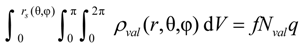
Performing the volume integration over the charge density up to this limit:
gives the fraction
f of valence charge density
Nvalq enclosed by the
rs(θ,φ) surface. The magnitude of
f is typically set to values around 90%. For the concept proposed here, it is assumed that the precise value of
f is chosen such that it assures the iso-density surface
rs(θ,φ) of neighboring ions to touch at a common point in the space between them. These points will be named contact points in the following.
The
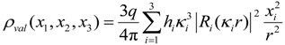
κ splitting will cause the spatial extension of the electron density to vary in different directions. This becomes obvious by re-writing Equation (3) for an ion at a triclinic, monoclinic or orthorhombic lattice site in Cartesian coordinates:
where the summation
i = 1…3 stands for
x,
y and
z. Insertion of Equation (1) yields for large
r values:
where rs and xs,i now stand for the radial and Cartesian coordinates of the iso-density surface. It is easily shown that Equation (7) describes a general ellipsoid for κ1 ≠ κ2 ≠ κ3. In addition, a careful analysis of Equation (7) reveals that the spherical character of the rs(θ,φ) should increase with quantum number n, i.e., the period of the ion within the periodic table. The iso-contour surface of electron density in the outermost regions of a p valence shell ion at triclinic, monoclinic and orthorhombic lattice sites accordingly is that of a general ellipsoid.
The shape simplifies to that of a rotational ellipsoid for κ1 = κ2 ≠ κ3, which is obeyed by p valence ions on trigonal, tetragonal and hexagonal lattice sites. It simplifies further to a sphere on cubic lattice sites, where κ1 = κ2 = κ3 holds. In the latter case, all terms in Equation (7) can be placed before the sum that ends up with Σ(x2 + y2 + z2), such that the whole equation just depends on the radial coordinate r and, thus, describes the shape of the sphere. Strictly speaking, these results would be valid only for either closed shell systems, all hi = 2, or half-closed shells, all hi = 1. It is realized from Equation (7) that any aspherical deformation would be amplified by a mixed occupation, i.e., valence shells with varying occupation numbers.
It can be concluded that the general shape Equation (7), firstly, motivates the success of the concept of ionic radii for the alkali halides and sphalerites, where ions occupy cubic sites of PG m3m and 43m. Secondly, it becomes evident why the ionic radii derived from these compounds do not apply to ions on lower symmetry sites. It may be understood that for the majority of bond distances, only rough approximations of the true bonding geometry were obtained with a single radius value, when, in fact, two or three radial parameters were required.
It is concluded that the general shape Equation (7) may yield a more accurate geometrical picture when applied to
p valence ions on crystal positions of non-cubic symmetry. That was the basics for the application of the approach in [
11], and its expansion will be tested in the following part for an extended set of compounds having the same crystal structure.
A pragmatic distinction seems helpful before starting the test. It will be supposed in the following that aspherical charge densities are more significant for anions than for cations. This is motivated by the smaller ionization energies of anions compared to cations. Hence, the difference of the anionic volume V− compared to that of the neutral atom Vat is larger than for cations: |V− − Vat| > |Vat − V+|. This rule holds at least for the most important ions of the second to fourth period, although the asphericity of cations may become equally important for higher periods.
3. Application to Pyrite-Structure Dichalcogenides
The approach will now be applied to metal dioxides, disulfides, diselenides and ditellurides MX
2 that crystallize in the pyrite structure; see
Table 1. It will not be endeavored to give a theoretical calculation of ionic wave functions according to the rules outlined in the previous section. Nor will the numerical values of
κ parameters or the fraction
f of enclosed valence electrons be determined. Instead, the ellipsoidal modelling of anions will be investigated by making use of highly precise structural data that have been determined for these compounds by diffraction experiments and which are also listed in
Table 1. As in the crystal radii approach, the ionic shapes will be chosen such that neighboring ions share a common contact point via their iso-density surfaces.
Table 1.
Lattice parameters of pyrite-type compounds MX
2. Unit cell edges
a and positional parameters
u were taken from cited references and used to calculate X–X and M–X bond length
dXX and
dMX. Metal ionic radii
rMSP were selected from SPS tables for VI-fold coordinated divalent metal ions [
7,
8]; spin-states were chosen in agreement with experimental data,
i.e., high-spin for Mn
2+ and low-spin for Fe
2+,
etc. Ellipsoidal radii
r||, r
⊥ and ionic volume
VX are given in the last columns as calculated from
dXX and Equations (8) and (9). Lengths are given in nm and volumes in nm
3.
Table 1.
Lattice parameters of pyrite-type compounds MX2. Unit cell edges a and positional parameters u were taken from cited references and used to calculate X–X and M–X bond length dXX and dMX. Metal ionic radii rMSP were selected from SPS tables for VI-fold coordinated divalent metal ions [7,8]; spin-states were chosen in agreement with experimental data, i.e., high-spin for Mn2+ and low-spin for Fe2+, etc. Ellipsoidal radii r||, r⊥ and ionic volume VX are given in the last columns as calculated from dXX and Equations (8) and (9). Lengths are given in nm and volumes in nm3.
| MX2 | a | u | Ref. | dMX | dXX | rMSP | r|| |
r⊥ | VX |
|---|
| MgO2 | 0.48441 | 0.4114 | [26] | 0.2083 | 0.1487 | 0.072 | 0.0743 | 0.1415 | 0.00623 |
| ZnO2 | 0.4871 | 0.413 | [27] | 0.2099 | 0.1468 | 0.074 | 0.0734 | 0.1413 | 0.00614 |
| CdO2 | 0.5313 | 0.4192 | [28] | 0.2308 | 0.1487 | 0.095 | 0.0744 | 0.142 | 0.00628 |
| FeS2 | 0.54160 | 0.38484 | [29] | 0.2263 | 0.2161 | 0.061 | 0.1080 | 0.1676 | 0.0127 |
| CoS2 | 0.55385 | 0.38987 | [30] | 0.2325 | 0.2113 | 0.065 | 0.1056 | 0.1704 | 0.0129 |
| NiS2 | 0.56852 | 0.39454 | [31] | 0.2398 | 0.2077 | 0.069 | 0.1038 | 0.1744 | 0.0132 |
| CuS2 | 0.57891 | 0.39878 | [32] | 0.2453 | 0.2030 | 0.073 | 0.1015 | 0.1766 | 0.0133 |
| MnS2 | 0.6104 | 0.4011 | [33] | 0.2593 | 0.2091 | 0.083 | 0.1046 | 0.1810 | 0.0143 |
| FeSe2 | 0.5783 | 0.386 | [34] | 0.2419 | 0.2284 | 0.061 | 0.1142 | 0.1836 | 0.0161 |
| CoSe2 | 0.58593 | 0.379 | [35] | 0.2437 | 0.2456 | 0.065 | 0.1228 | 0.1804 | 0.0167 |
| NiSe2 | 0.59629 | 0.383 | [35] | 0.2488 | 0.2417 | 0.069 | 0.1208 | 0.1820 | 0.0168 |
| MnSe2 | 0.6417 | 0.393 | [36] | 0.2702 | 0.2379 | 0.083 | 0.1189 | 0.1908 | 0.0181 |
| MgTe2 | 0.70212 | 0.3875 | [26] | 0.2941 | 0.2736 | 0.072 | 0.1368 | 0.2257 | 0.0292 |
| MnTe2 | 0.6943 | 0.386 | [36] | 0.2904 | 0.2742 | 0.083 | 0.1371 | 0.2103 | 0.0254 |
The geometry of bonding in pyrite-type disulfides has recently been modelled under the assumption of spherical ion shapes [
11]. This is visualized by a 3D plot for the prototype compound FeS
2 in
Figure 1. The cubic pyrite structure contains four formula units MX
2 per unit cell with anions residing on three (
C3) and cations on
3 (
C3i) lattice sites; further structural details are given in the figure legend and [
37]. For plotting
Figure 1, cation radii
rMSP were taken from the SPS listing [
7,
8], while the radius of sulfur anions was naturally chosen as half the sulfur dumbbell distance,
rS =
dSS/2. It turned out that the calculation of the interatomic Fe–S distance
dFe–S by simply summing up
rMSP and
rS resulted in a 25% deviation from the experimental value. This insufficiency of the spherical model was not only obtained for FeS
2, but equally observed for all compounds listed in
Table 1. It demonstrates the inadequacy of the spherical modelling for pyrite-type crystals.
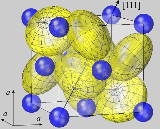
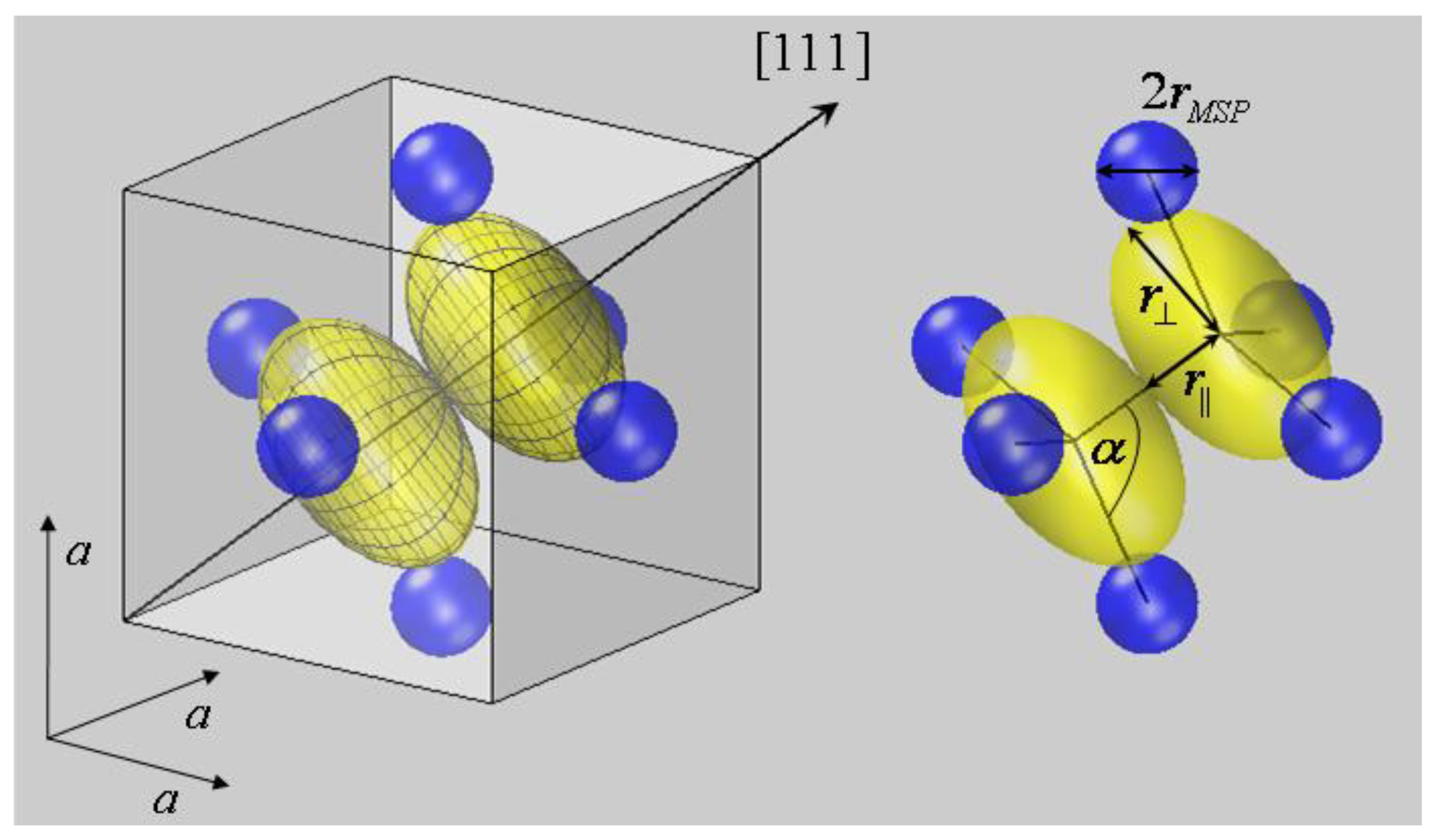
Figure 1.
Spherical modelling of the pyrite unit cell (space group
Pa3). While Fe
2+ ions (blue) form an fcc lattice, sulfur ions (yellow) reside on <111> axes, as described by positional parameter
u. In FeS
2 u amounts to 0.38484 in fractional coordinates of the unit cell [
38]. The body diagonal is shown as an arrow. S ions form dumbbells, and there are four S
2 dumbbells in the unit cell. Only the dumbbell at (
uuu) and (
ūūū) appears undivided, while the remaining S
2 dimers all extend from the cell shown into neighboring cells. In order to visualize the different site symmetries, a mesh is inscribed into S ion spheres with poles lying on <111> symmetry axes. All ions are modelled by spheres with radii
rMSP for Fe
2+ and half the S–S bond distance
dSS/2 for S
−. With this setting, Fe and S spheres have contacts with none or only one neighbor, respectively. This result also holds for the other compounds listed in
Table 1. Such a spherical packing would be unstable in terms of packing theory [
2], demonstrating the failure of the ionic radius concept in the case of pyrite-type compounds.
![Crystals 04 00390 g001]()
As mentioned before, a possible asphericity of cations will be neglected. Therefore, metal ions in the pyrite structure are assumed to exhibit the shape of spheres, and
rMSP values were again taken from the SPS listing [
7,
8]. Only those pyrite-structure dichalcogenides were selected to enter into
Table 1, for which a radius value for a six-fold-coordinated M
2+ was given in the SPS listing. Hence, the availability of these data served as a selection criterion for the compounds to be investigated here.
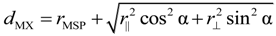
Charge densities of monovalent X anions, however, have to be modelled by ellipsoids. A nearly sp3 hybridization was assumed to account for their electronic configuration as deduced from their tetrahedral coordination. Since the electron density is assumed to scale with the square of electron wave functions, the hybridization does not affect the splitting of p levels into symmetry-adapted states. It is well known that the p orbitals in a three symmetry span a one-dimensional A and a two-dimensional E representation. Accordingly, two contraction-expansion parameters κ|| and r⊥ are needed to describe the spatial extension of chalcogen ion ellipsoids, which correspond to one radius r|| along the <111> symmetry axis and another radius κ⊥ perpendicular to it. Rotational ellipsoids of initially unknown principal extension where accordingly placed on X lattice sites in the second step of the geometrical construction.
The lengths of the major axes of X ellipsoids were determined in the third step by varying
r|| and r
⊥ until the first contact with the iso-surfaces of lattice neighbors was obtained. This construction is easily performed for
r||, since its magnitude is simply given by half the dumbbell distance,
r|| =
dXX/2. The geometrical derivation of r
⊥, however, is more complex. It can be seen from the bonding geometry shown in
Figure 2 that the metal-chalcogen distance
dMX should be decomposed in the metal radius
rMSP and half of the diameter of the chalcogen ellipsoid, with the diameter chosen to lie in the direction of the M–X internuclear axis [
11]. Since the ellipsoid diameter depends on both
r|| and r
⊥, the equation:
holds, where α is the M–X–X bond angle, and cosα =
3 is valid in the pyrite structure. From this equation, r
⊥ can be derived, if the other quantities are known. From a geometric point of view, the solution of Equation (8) for known values of
dMX,
rMSP,
r|| and α corresponds to varying r
⊥ until the X ellipsoid comes in contact with the neighboring M spheres. The obtained X ellipsoid with the radii
r|| and r
⊥ is visualized in
Figure 2 for FeS
2, where the neighbors of the first bonding spheres of an S
2 dumbbell are shown.
Figure 2.
Bonding coordination of the sulfur dumbbell in FeS
2 at (
uuu) and (
ūūū). (
a) Within the crystallographic unit cell and (
b) as S
2Fe
6 cluster with internuclear axes. According to the presented approach, ellipsoidal deformations are allowed to occur for S anions on three (
C3) symmetry sites, but might be neglected for Fe cations. The bond partner of sulfur dimers S
2 form two interpenetrating tetrahedrons with the neighbor S residing on top and three Fe
2+ forming the basis. The tetrahedrons itself are compressed as are the sulfur ellipsoids. The latter exhibit a smaller radius parallel to the <111> axis
r|| compared to the perpendicular radius r
⊥. Comparable geometries are found for the other pyrite-type compounds listed in
Table 1.
Equation (8) re-establishes the additivity of the interatomic distance by decomposing it into the metal ionic radius plus a weighted sum of ellipsoidal radii with weighting factors given by the direction cosine and direction sine with respect to the inter-nuclear axis. The formula exemplarily shows that interatomic distances in crystals indeed exhibit an additivity rule. However, bond distances d are not simply obtained by adding two ionic radii, like rM and rX, but derive from a geometrically more complex scheme that has to comply with the crystal symmetry and the relative orientation of valence orbitals. Only this procedure is in accordance with Neumann’s principle.
Finally, also the volume of chalcogen ellipsoids can be derived from:
with r
⊥ entering quadratically, as both perpendicular directions are equivalent.
4. Results and Discussion
The three parameters of interest,
r||, r
⊥ and
VX, were analyzed with this ansatz for all MX
2 investigated in this work, and the results are also compiled in
Table 1. It can be seen that the magnitude of the equatorial radius r
⊥ exceeds that of the polar radius
r|| in all cases. In terms of contraction-expansion parameters, this result is equivalent to
κ|| > κ
⊥. Accordingly, chalcogen ions exhibit the shape of oblate ellipsoids being compressed along <111> axes.
The compression of chalcogen ellipsoids towards X anions and their elongation in the perpendicular direction appears very plausible from an electrostatic point of view. This suggests that electrons of one anion in the vicinity of the X–X internuclear axis are repelled by the negative charge of the neighboring anion. In addition, they are also attracted towards the cations, the combination of both effects causing the oblate appearance.
The deformation ratio of chalcogen ions r
⊥/
r|| is seen in
Table 1 to increase in the sequence O > S > Se > Te. This development is fully in accordance with the statement that r
⊥/
r|| should diminish with principal quantum number
n for an otherwise unchanged energy splitting, as may occur for a nearly constant crystal-structure surrounding when going from one pyrite-structured dichalcogenide to another.
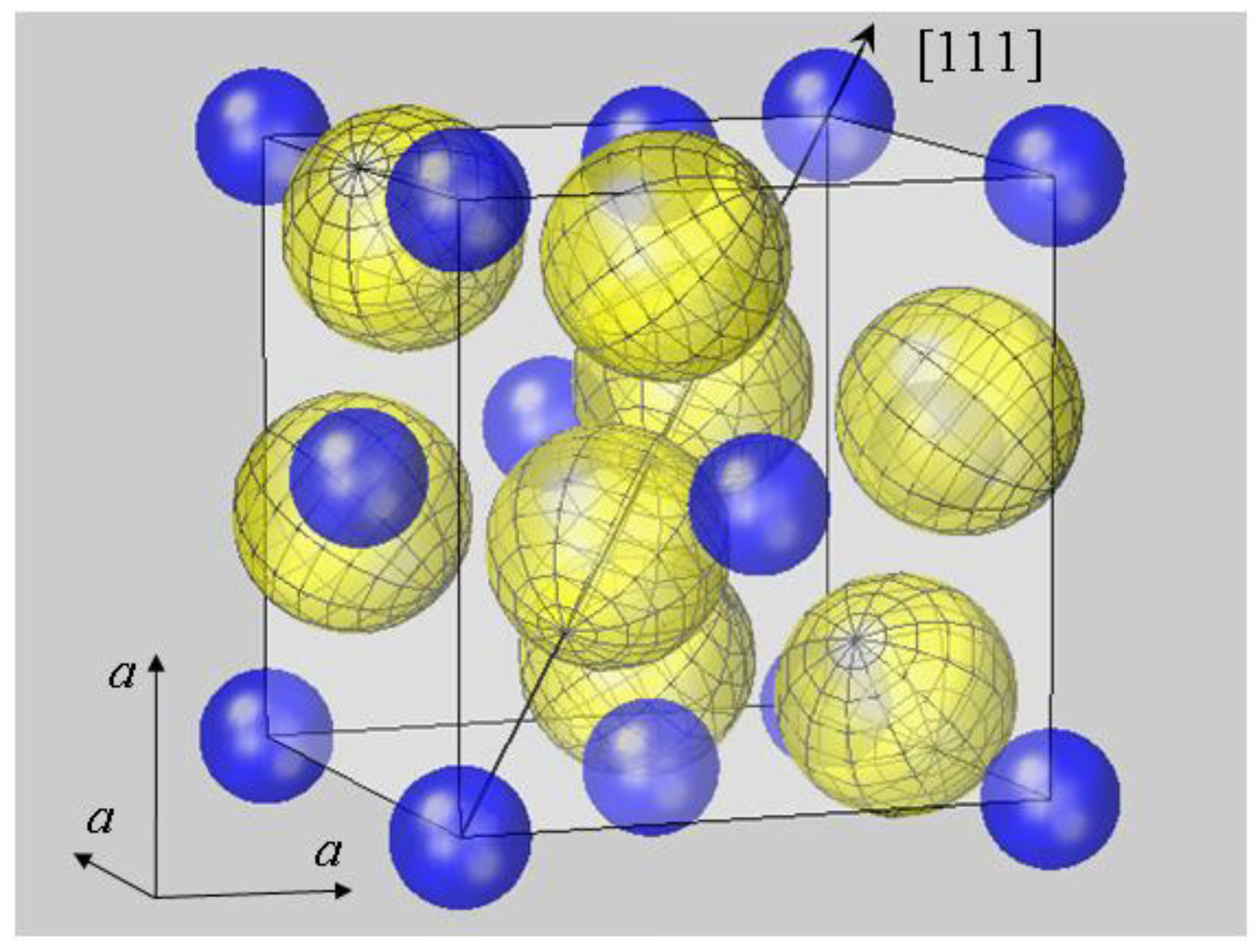
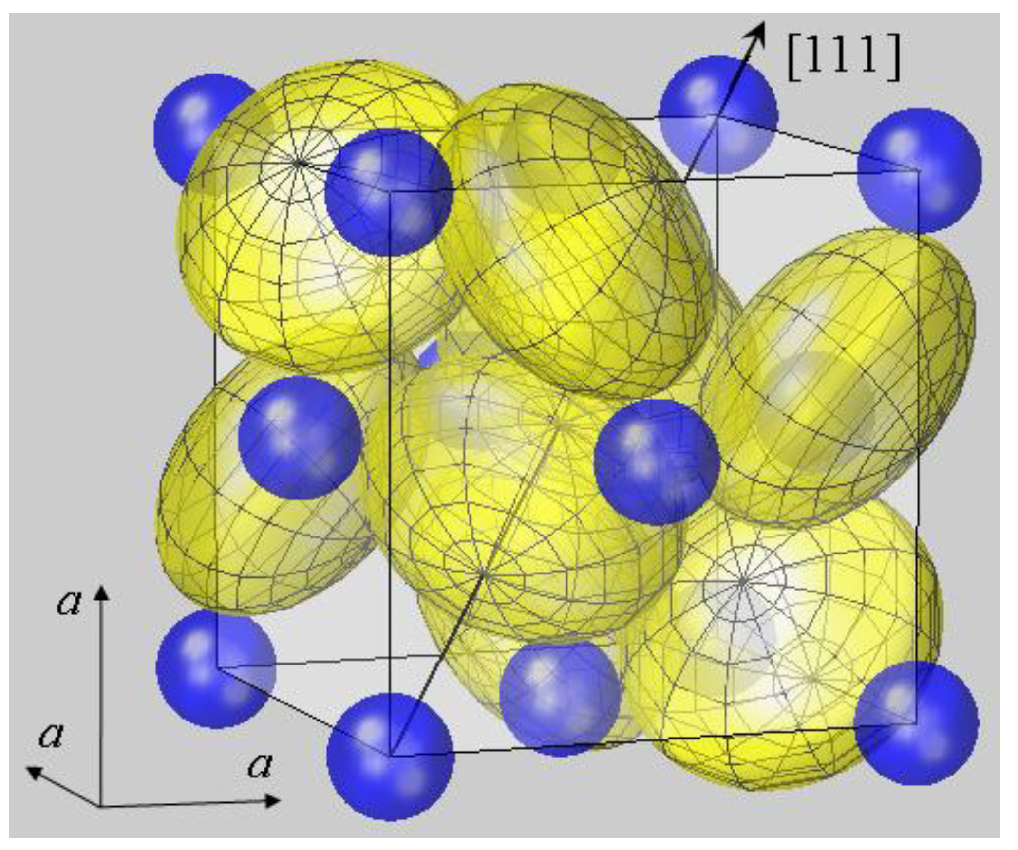
Figure 3 displays the aspherical modelling for the prototype compound of the pyrite structure, which is the first visualization of the FeS
2 crystallographic unit cell that is adequately modelled with ellipsoidal sulfur ions.
The presented modelling appears unfamiliar, since we have got acquainted to consider ionic shapes along bond distances, as in molecules. In the new approach, however, the shape is decomposed along symmetry axes and perpendicular axes because of the orthonormality of p orbitals. For the chalcogen ions in pyrite crystals, the second ellipsoidal axis is not directed along the M–X bond axis, but perpendicular to C3. This procedure makes the new picture difficult to grasp. On the other hand, the model is more in accordance with the crystalline state, where chemical bonding is not a phenomenon between neighboring atoms, but between one ion and all other ions of the crystallite.
Derived data appear also interesting with respect to the volume of chalcogen ions
VX. Their values, as calculated from
r|| and r
⊥ according to Equation (8), are given in
Table 1. It can be seen that ionic volumes compare very well, when compounds with equal chalcogen ions are compared (O
−, S
−, Se
− and Te
−). It must be remembered that the accuracy of metal ionic radii is only on the order of some percent [
7,
8], which suggests that the scatter in
VX values may practically vanish, if small corrections on
rMSP would apply.
Figure 3.
A new look at the pyrite structure: crystallographic unit cell of pyrite FeS
2 with Fe and S ions modelled by spheres and ellipsoids, respectively. Radial parameters
rMSP for Fe
2+ and
r|| and r
⊥ for S
− were used as given for FeS
2 in
Table 1. The mesh inscribed into the sulfur ions now reveals the ellipsoidal compression along <111> directions. In this model, the number of contact points of S and Fe ions become four and six, respectively, and the ellipsoidal deformation is concluded to enable a stable packing.
Table 2 lists the average values of
VX as obtained from each group of MX
2. The data are found to exhibit a monotonic increase from O to Te, as expected. The respective standard deviations δ
VX have also been given, which are perceived to be on the order of 1.7%. These variations are rather small when compared to other approaches for the geometrical modelling of pyrite-type compounds. They will even diminish when transformed from a volume scale to a length scale to compare their accuracy with data derived from the ionic radius concept.
Such an appropriate length scale is given by the sphere-equivalent radius
rx of chalcogen ions, which is derived from
![Crystals 04 00390 i020]()
and stands for the radius a spherical X
− ion would have. Sphere-equivalent radii
rx were calculated for each compound investigated here, and averages were formed for the groups of dioxides, disulfides,
etc.
The data are also given in
Table 2, and their respective standard deviations δ
rx are seen to range from 0.3% to 2.3%. This is a rather small scatter compared to the conventional crystal radii approach [
7,
8] and again signifies the reliability of the approach introduced here. Furthermore, the calculation of interatomic distances now yields only small deviations from experimental data in the few percent range, when their calculation is based on
VX values given in
Table 2 and the
dMX decomposition according to Equation (8).
The physical significance of the ionic volume data
VX is underlined by a comparison with the volumes of chalcogen atoms
Vat and divalent ions
Vdi. Accurate data for them can be obtained from the literature, where they were either obtained through theoretical calculation or were determined from sphalerite-type compounds [
7,
8,
39].
Table 2.
Spherically-averaged radii and volumes of chalcogen atoms and ions with radii given in nm, volumes in 10
−3 nm
3 and relative errors δ
rx and δ
VX in %. Numbers in parenthesis give the standard deviations for the last digit(s) of the preceding value. Averaged data of monovalent ions
rx and
VX were derived as outlined in the text, while spherical volumes of chalcogen atoms
Vat and tetrahedrally coordinated divalent ions
Vdi were calculated from their radii given in [
39] and [
7,
8], respectively.
Table 2.
Spherically-averaged radii and volumes of chalcogen atoms and ions with radii given in nm, volumes in 10−3 nm3 and relative errors δrx and δVX in %. Numbers in parenthesis give the standard deviations for the last digit(s) of the preceding value. Averaged data of monovalent ions rx and VX were derived as outlined in the text, while spherical volumes of chalcogen atoms Vat and tetrahedrally coordinated divalent ions Vdi were calculated from their radii given in [39] and [7,8], respectively.
| X | rx | δrx | VX | δVX | Vat | Vdi |
|---|
| O | 0.1141(4) | 0.3 | 6.22(6) | 1.0 | 1.2 | 11.0 |
| S | 0.1469(21) | 1.4 | 13.3(6) | 4.3 | 4.71 | 26.1 |
| Se | 0.1593(15) | 1.0 | 16.9(7) | 4.3 | 6.71 | 32.5 |
| Te | 0.1867(43) | 2.3 | 27(2) | 7 | 10.77 | 45.2 |
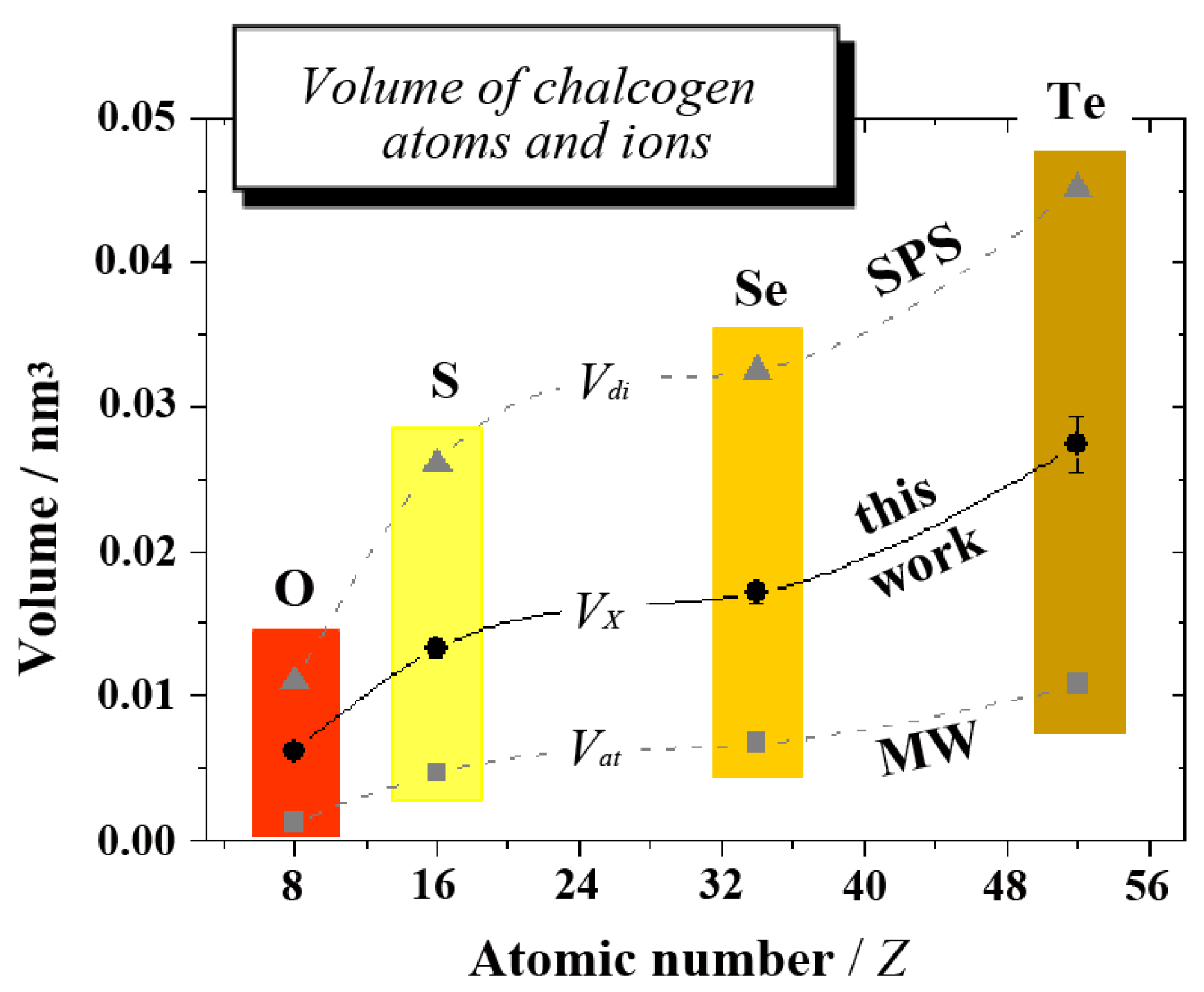
The comparison is visualized in
Figure 4, where the three different volumes are displayed as a function of atomic number
Z. In regard to many details, such as substantial increases between O and S or Se and Te,
etc., the volume of monovalent ions
VX is seen to follow the same trend as
Vat and
Vdi. Moreover,
VX values consistently range between 50% and 60% of divalent ions
Vdi. The trend in
VX and the absolute values can thus be considered to be very reliable.
The results imply considering the derived VX values rather than a single radius as a crystal-chemical constant, which are attained by the specific ion in different crystalline solids. The distinction is irrelevant for ions on cubic lattice sites for which the concept of crystal radii has initially been developed. It becomes important, however, when ions on positions with lower site symmetry are considered. In these cases, rather, the crystal volume seems to be conserved, while the ion’s extension in different directions will depend on existing symmetry axes and their relative orientation. The shape of a p valence shell ion has to be modelled by a general ellipsoid for ions on low-symmetry sites. Monovalent chalcogen ions O−, S−, Se− and Te− in pyrite-type compounds exhibit remarkably consistent volumes when modelled by ellipsoids in accordance with the presented formalism.
Figure 4.
The volume of chalcogen atoms and ions as a function of atomic number
Z (data are given in
Table 2). In the plot,
Vat stands for the volume of covalent atoms (from [
39], MW),
VX for monovalent ions as derived in this work and
Vdi for divalent ions (from [
7,
8], SPS). Continuous and dashed lines merely serve as a visual guide.


 , with principal quantum number n [20]. Rnl stands for the radial function that determines the ions spatial extension and κnl is the contraction-expansion parameter having the dimensionality of an inverse length. Strictly speaking, Rnl does not only depend on the radial coordinate r, but on its product with κnl having Rnl = Rnl(κnlr). The parameter κ is usually associated with an effective nuclear charge Zeff via κ = Zeffmq2/(2πε0ћ2n) in order to account for screening (m electron mass, q elementary charge, ε0 permittivity of vacuum). Moreover, κ is related to the bonding energy of the electronic level via En = −κ2ћ2/(8m) [20].
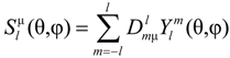
 is unequivocally defined for each of the 32 PG; for a tabulation, see [25]. The symmetry-adapted basis functions
  of l = 1 states can be represented for most cases by p orbitals or real spherical harmonics ylm± that derive from spherical harmonics via
 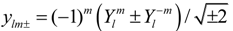 for |m| = 1 and yl0 =
  for m = 0. Then, the Cartesian coordinate system has to be oriented along the main symmetry axes of the lattice site, like the z-axis along the major axes of rotation, etc.
 alone, but also the radial functions, causing Rnl → Rnlµ. This becomes evident from the observation that symmetry adapted basis functions spanning different irreps, like
  and
and  , are not transformed into each other under the symmetry operations allowed by the PG. For instance, a pz orbital extending along the symmetry axis of a 3 (C3) lattice site does not transform to px or py under any symmetry operation contained in the group.


 and stands for the radius a spherical X− ion would have. Sphere-equivalent radii rx were calculated for each compound investigated here, and averages were formed for the groups of dioxides, disulfides, etc.