Article

All MOVPE Grown Quadruple Junction InGaP/InGaAs/Ge/Ge Solar Cell

RSE, Via V. Callegari, 21, 29122 Piacenza, Italy
*
Author to whom correspondence should be addressed.
Crystals 2025, 15(9), 816; https://doi.org/10.3390/cryst15090816
Submission received: 29 August 2025 / Revised: 15 September 2025 / Accepted: 16 September 2025 / Published: 18 September 2025
(This article belongs to the Special Issue Crystal Growth of III–V Semiconductors)

Abstract

Most commercially available InGaP/InGaAs/Ge triple-junction solar cells suffer from current mismatch due to the excess current generated by the Ge sub-cell. Combining epitaxial germanium with III–V materials would enable the realization of lattice-matched four- or five-junction solar cells, where the near-infrared spectrum could be split between two Ge sub-cells instead of one, thereby eliminating current mismatch in these devices and achieving higher conversion efficiency. In this work, we present the first demonstration of a quadruple-junction (4J) InGaP/InGaAs/Ge/Ge device, with all layers sequentially deposited in the same MOVPE growth chamber. The 4J device also features a novel architecture that exploits the “transistor effect” between the two Ge junctions to eliminate the current mismatch in the upper 3J InGaP/GaAs/Ge part. We describe the growth and the cell structure realization strategy developed to overcome—and, where beneficial, to exploit—the cross-contamination between III–V and group IV elements, thus avoiding the need for two separate deposition systems. The structural and electrical characterizations performed to ascertain the 4J device quality are presented. This result represents a key step toward the realization of highly efficient, all-MOVPE-grown, lattice-matched MJ solar structures that combine III–V and group IV alloys.

1. Introduction

In photovoltaic conversion, only photons having more than the semiconductor threshold energy (the bandgap, Eg) are absorbed to produce electric carriers and then generate external work. A single pn junction realized with the same semiconductor material has one-sun limiting efficiency around 30% [1], because, once the Eg value is decreased to improve the photovoltaic current, the output voltage of the solar cell is also reduced. We must therefore accept less voltage to obtain more current. One way to overcome the “give and take” balance limitation is to consider the multijunction (MJ) solar cell concept.
The MJ solar cell is an optoelectronic device formed by a stack of pn junctions, realized with different materials, connected in series by tunnel junctions, whose Eg values are usually decreased from the top to the bottom of the device, resulting, in the simplest case, in a two-terminal electrical output device. In an MJ solar cell, the “give and take” balance limitation between the current and the voltage can be overcome, as it is possible to collect photons over a wide wavelength region and, at the same time, obtain a voltage that is the sum of the voltages produced by the series-connected junctions. A “workhouse” lattice-matched, MJ solar cell is the 3-junction InGaP/InGaAs/Ge one, whose bandgaps decrease from 1.85 eV of the top InGaP junction to 1.4 eV of the middle InGaAs junction and then to 0.67 eV of the bottom Ge junction. Such a device, having all materials with the same lattice parameter, presents a high structural quality, with one-sun theoretical efficiency between 31 and 34% depending on the solar spectrum [2].
The possibility of realizing III–V-based lattice-matched MJ devices with more than three junctions has unfortunately clashed with the limited availability of suitable materials. Over time, alternative MJ solutions have been developed, in which attempts have been made to combine materials with different lattice constants.
This is the case, for example, of metamorphic MJ solar cells, that is, MJ device structures that remain in a metastable state in which the concentration of defects does not reach the equilibrium value [3]. A remarkable result has been obtained with a 6-junction metamorphic AlInGaP/AlGaAs/GaAs/InGaAs(3) MJ solar cell reaching a one-sun efficiency of 39.2% [4]. The disadvantage of this approach is the need to use thick substrates to reduce the wafer bending that forms during growth, since lattice mismatch introduces strain in the epitaxial layers. Buffer layers are also needed to confine the dislocations that are generated by the lattice mismatch when the epitaxial layers overcome the critical thickness.
A further solution has been to apply the wafer bonding technique [5]. This approach allows integrating dissimilar semiconductor materials at lower temperatures than those used in epitaxial growth. For a 4-junction GaInP/InGaAs//InGaAsP/GaInAs bonded cell (where the double slash indicates that the bonding has been carried out between the InGaAs and GaInAsP junctions), a world record efficiency of 47.6% has been achieved at a concentration of 665 suns [6]. Unfortunately, also, the use of wafer bonding for device fabrication has some drawbacks, mainly attributed to the additional costs and machine time.
So far, alternative solutions to lattice-matched MJ solar cells have been demonstrated to be expensive, with complicated growth processes or device fabrication and larger material utilization.
This has motivated the search for further lattice-matched multi-junction (MJ) solar cell architectures and a realization process for optimal solar energy harvesting and device cost reduction, trying to overcome the fundamental problems that have hindered their development.
Among them, we must consider the cross-contamination between III–V and IV elements that, for example, did not allow a commercially competitive technological path for 4-junction InGaP/InGaAs/Ge(SiSn)/Ge and 5-junction AlInGaP/AlInGaAs/InGaAs/Ge/Ge solar cells. Such cell structures can reach an efficiency increment between 1.5% and 5% with respect to the 3-junction InGaP/(In)GaAs/Ge structure [7,8,9]. In the InGaP/InGaAs/Ge structure, in fact, the Ge sub-cell generates about twice as much photocurrent as the other sub-cells, resulting in half of the photocurrent being wasted in the series connection of sub-cells. The large current difference is due to the large energy gap difference between the III–Vs and Ge, and it could only be reduced by thinning the Ge substrate, for example, by chemical etching, from the standard thickness value of 150–180 µm to a few microns. This would introduce yield problems owing to the manufacturing process of very thin solar cells. Higher MJ solar cell efficiency can thus be obtained if the near infrared spectrum is divided between two Ge sub-cells or between SiGeSn and Ge sub-cells rather than being utilized in one Ge junction.
These MJ structures have not found an application yet, because, owing to the cross-contamination problem, the integration of IV elements with III–Vs for realizing these devices has required two different types of growth equipment: a chemical vapor deposition (CVD) reactor for the growth of IV elements and a metal–organic vapor-phase epitaxy (MOVPE) growth apparatus for the deposition of the remaining III–V part of the cell structure [10,11]. The utilization of two pieces of growth equipment introduces higher capital expenditure (industrial-grade systems with advanced capabilities can exceed USD 1 million) and does not bring economic advantage for these monolithic architectures.
In this contribution, we present the first demonstration of a 4J InGaP/GaAs/Ge/Ge device, with all layers sequentially deposited in the same MOVPE growth chamber and in the same deposition run. The 4J device also features novel architecture, with a third terminal inserted between the two Ge junctions to avoid the tunnel diode connection and the possibility to exploit the “transistor effect” to transfer the power between the two Ge junctions, thus eliminating the current mismatch in the upper 3J InGaP/GaAs/Ge part. Preliminary growth studies at the materials level and on single junction devices have been carried out by the authors (see [12]), arriving at the conclusion that III–V and IV-based monolithic architectures grown in the same MOVPE apparatus can be feasible for realizing high efficiency MJ solar cells at a lower cost. Here, for the first time, we present a full 4J cell structure growth, and the device strategy developed to overcome—and, where beneficial, to exploit—the cross-contamination between III–V and group IV elements, thus avoiding the need for two separate deposition systems. To ascertain the material deposition quality, layer morphology, high-resolution X-ray diffraction, in situ reflectance, and curvature measurements have been carried out. Functional devices have been realized, and external quantum efficiency and current and voltage measurements have been performed to assess electrical and photovoltaic performances. To demonstrate that the cross-contamination among III–V and IV elements when deposited in the same MOVPE chamber can be controlled and even exploited at the MJ device level, the photovoltaic performances of 4J InGaP/GaAs/Ge/Ge and 3J InGaP/GaAs/Ge functional devices, the last one deposited in a clean MOVPE reactor, have been compared.

2. Materials and Methods

The III–V and group IV-based semiconductor deposition has been accomplished by means of the AIX 2800G4 MOVPE “planetary” system (from AIXTRON SE, Herzogenrath, Germany). The MOVPE system has been equipped with instrumentation from Laytec EpiCurve® TT, Berlin, Germany, which includes a multi-wavelength optical reflectometer (950 nm, 633 nm, and 405 nm) for the growth rate determination and surface roughness monitoring, an emissivity-corrected pyrometer for in situ wafer temperature measurement, and a deflectometer for the wafer bowing measurements.
To pursue an industrial scale-up of the growth process, only commercially available gas sources and metalorganic precursors have been selected. The growth of AlAs, GaAs, InGaAs, and (Al)InGaP has been carried out by using AsH3, PH3, TEGa (Ga(C2H6)3), TMGa (Ga(CH3)3), TMAl (Al(CH3)3), and TMIn (In(CH3)3), while DEZn (Zn(C2H6)2) and Si2H6 have been used as dopants sources, respectively, for p-type and n-type doping. Growth of III–Vs has been carried out by using H2 as a carrier gas. The deposition of Ge has been accomplished by using GeH4 (10% in N2), using N2 as a carrier gas; TMGa (Ga(CH3)3) was used for p-type doping. The reactor pressure has been kept constant at 50 mbar, while the growth temperature has varied between 733 K and 863 K. Four-inch and six-inch Ge p-type substrates with an orientation (100) 6° off towards <111> have been used.
The layer morphology has been evaluated by an optical microscope (Leica DM 4000 M, Weizlar, Germany) with different magnifications. The growth rate has been computed by fitting the MOVPE in situ reflectivity curves. Structural characterization has been carried out by high-resolution X-ray diffraction (HRXRD with a BRUKER D8 Discovery system (BRUKER, Ettlingen, Germany).
The device characterization has been performed by means of external quantum efficiency measurements with a home-made system, while current–voltage characteristics have been measured under an AM1.5d-ASTM-G173-3 one-sun spectrum produced by a four-lamp flash tester (TECHNOEXAN Ltd., St. Petersburg, Russia). The light spectral distribution and intensity of the flash tester are calibrated with 3-component reference InGaP, InGaAs, and Ge devices. Dark I–V curve has been measured with a Keithley source meter of series 2450.

2.1. MOVPE Growth Strategy

To overcome the cross-contamination among III–V and IV elements, a MOVPE reactor chamber modification is first introduced. After gas precursor cracking, different atoms deposit on the reactor susceptor and reactor ceiling. To reduce their inclusion in the epitaxial layers, the deposition on these components must be reduced. This objective has been achieved by inserting a quartz plate in the center of the graphite susceptor, which stays at a substantially lower temperature than the susceptor and thus allows for the minimization of the deposition at the chamber center zone upstream of the leading wafer edge. Besides this, a new triple gas injector was developed. This gas injector is already proposed to introduce separately the hydrides and metalorganic precursor at different heights in the MOVPE reactor chamber, with the purpose of enhancing the control on the deposition process [13]. In our MOVPE reactor, it is characterized by a larger diameter than standard. As far as the ceiling is concerned, a better thermal decoupling between the ceiling and the top reactor cooling plate has been accomplished, which allowed for the decrease of the unwanted parasitic deposition also on this zone of the reactor chamber (see Figure 1).
The growth activity was first focused on assessing and qualifying the growth chamber modification, setting up the new growth conditions for epitaxial germanium and III–Vs. Growth temperature was lowered, and the growth rate increased, trying to preserve an excellent layer morphology. Decreasing the growth temperature helped to reduce the evaporation of atoms deposited on the reactor susceptor. While increasing the growth rate, any unwanted impurity could be diluted in the deposited material. By reducing the growth temperature, the kinetic growth regime can be reached, a reduction in the precursor cracking efficiency can be encountered, and a difficulty in increasing the growth rate should be expected. The introduction of a special triple gas injector was then important for enhancing the precursor utilization efficiency, allowing the temperature values to be even lower than 723 K and nevertheless reaching growth rates higher than 100 nm/min. The growth rate of epitaxial germanium was maximized by injecting GeH4 into the growth chamber from the bottom part of the triple gas injector.
Besides reducing the temperature and increasing the growth rate, the Ge memory effect in III–V layers [14] was effectively reduced by adopting proper buffer layers, a few microns thick, deposited between the group IV- and III–V-based layers. The growth strategy first implemented at the material and at the single junction level [15] has then been transferred to the MJ device level, adopting a proper device strategy realization.

2.2. MJ Device Strategy Realization

When depositing Ge in a III–V contaminated reactor, the first part of the Ge nucleation is always strongly n-type, with a doping concentration exceeding 1018 cm−3. During the Ge deposition, the concentration of the n-type contaminant (mainly arsenic from AsH3 decomposition) decreases, and it is possible to switch the semiconductor polarity from n-type to p-type by introducing TMGa as the dopant source. By selecting proper solar cell polarity and architecture, the residual arsenic contamination, instead of being a problem, can, on the contrary, be usefully exploited.
Referring to Figure 2, the realized 4J InGaP/InGaAs/Ge/Ge solar cell presents an upper 3J InGaP/InGaAs/Ge–1 part, with n on p polarity, grown over a bottom Ge–2 part, with a p on n polarity. The bottom Ge–2 sub-cell does exploit the residual group V (As) doping in the growth chamber for producing an n-type layer, over which a Ge p-type layer is deposited. The realization of the n-layer in the Ge–1 sub-cell is accomplished by exploiting the solid-state diffusion of phosphorus from the upper InGaP window layer. This solution is also used for the bottom Ge sub-cell in a conventional n on p 3J InGaP/GaAs/Ge structure; however, in this last case, the phosphorus diffuses into the bottom p-type substrate, generating a compensated n-type emitter layer. In our proposed 4J device, after the deposition of the Ge p-type layer, an undoped Ge layer is grown, whose background doping is around 1016 cm−3 and it is n-type; therefore, the phosphorus diffuses in a layer with the same polarity, no compensation takes place, and a better emitter minority carrier diffusion length can be obtained. Before the first tunnel diode, a proper InGaAs buffer layer is inserted to incorporate the residual germanium into the growth chamber. The rest of the III–V layers are then grown as in a standard 3J InGaP/InGaAs/Ge cell, but at a reduced temperature (see Section 3.1).
The 4J device foresees three terminals (T): one on the front side, one positioned between the two bottom Ge sub-cells, to avoid the tunnel diode connection, and the last one on the back side of the 4J device. Since the Ge p-type layer is grown with a thickness much lower than the electron diffusion length, the bottom Ge–1/Ge–2 structure of the 4J device results in an n–p–n transistor-like structure, with the upper Ge n+-type layer acting as emitter, the Ge p-type layer as base, and the bottom Ge n+-type layer as collector. The “transistor effect” can thus be exploited to transfer the excess of power from the top Ge junction to the bottom one, eliminating the current mismatch in the upper InGaP/InGaAs/Ge–1 part [16].
For the “proof of the concept”, a 4J functional device has been realized in a simplified form: it only has a front busbar contact and no front grids. In the attempt to minimize the series resistance, it is also characterized by a small area (see Figure 2b), and the InGaP top sub-cell has a thicker emitter (around 200 nm) with respect to one used for a conventional 3J InGaP/GaAs/Ge structure (around 60 nm).

3. Results and Discussion

3.1. MOVPE Growth Results and Discussion

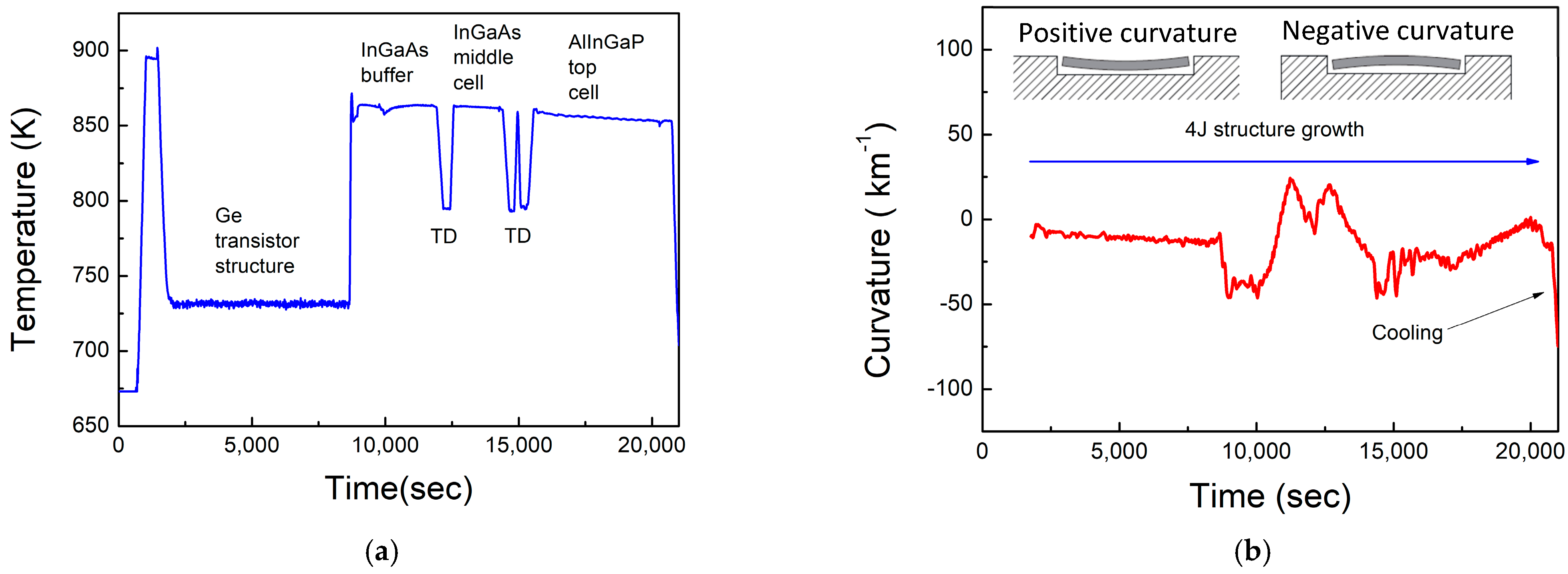
The wafer surface morphology was double checked by monitoring the reflectance behavior at 405 nm during the cell’s structure deposition and by an optical microscope at the end of the MOVPE run (see Figure 3). Thick layers with good morphology present a flat reflectance behavior. A slight increase in the roughness of the surface can be distinguished only at the end of the Ge layer (see Figure 3a). Since in a III–V contaminated growth chamber, V-element doping in Ge is strong, Ge has been grown at a very low temperature (see Figure 4a) and at a moderately high growth rate of 6 µm/h. A higher growth rate leads to a higher deterioration of the layer’s morphology. The determined growth conditions were sufficient to manage the group V contamination, switching from n-type to p-type conductivity after a proper time, maintaining sufficiently good morphology.
The temperature and curvature profile measured during the 4J structure deposition are reported in Figure 4. A much lower temperature is required for Ge deposition compared to III–V to control the MOVPE growth chamber contamination in the layer. A relatively higher temperature has been used for the tunnel diode depositions. The middle and the top cell structures have been deposited around 863 K to obtain a better surface morphology. From the material to device level, the morphological aspects become more important, as reduced roughness usually leads to interfaces with a reduced carrier recombination velocity, resulting in better device photovoltaic performances. To achieve excellent layer morphology, we had to increase the growth temperature of III–V from 773 K, the optimum value originally determined to reduce the IV group contamination at the material level [12], to 863 K. This temperature is still sufficiently low to avoid group IV contamination both in the tunnel diode and photovoltaic active III–V layers, once a proper InGaAs buffer layer, 3.5 µm thick, deposited with a growth rate of 7 µm/h, is introduced.
Selecting proper cell polarity is not only important in the first phase of Ge nucleation but also for the growth of the buffer layer. In fact, Ge is an n-type contaminant in III–V; therefore, the right cell polarity can also be maintained during the InGaAs buffer deposition.
Once the middle cell’s structure has been grown, it is possible to lower the growth rate to 1.8 µm/h for the AlInGaP top cell to obtain excellent morphology and the expected bandgap.
As reported in Figure 4b, the same curvature values are measured at the beginning and at the end of the 4J deposition, showing that the tensile and compressive strain in the structure compensate each other. During the cooling, a negative (i.e., concave) curvature is obtained, reaching a value near 100 km−1, owing to the different thermal expansion coefficients between the Ge substrate and III–V layers.
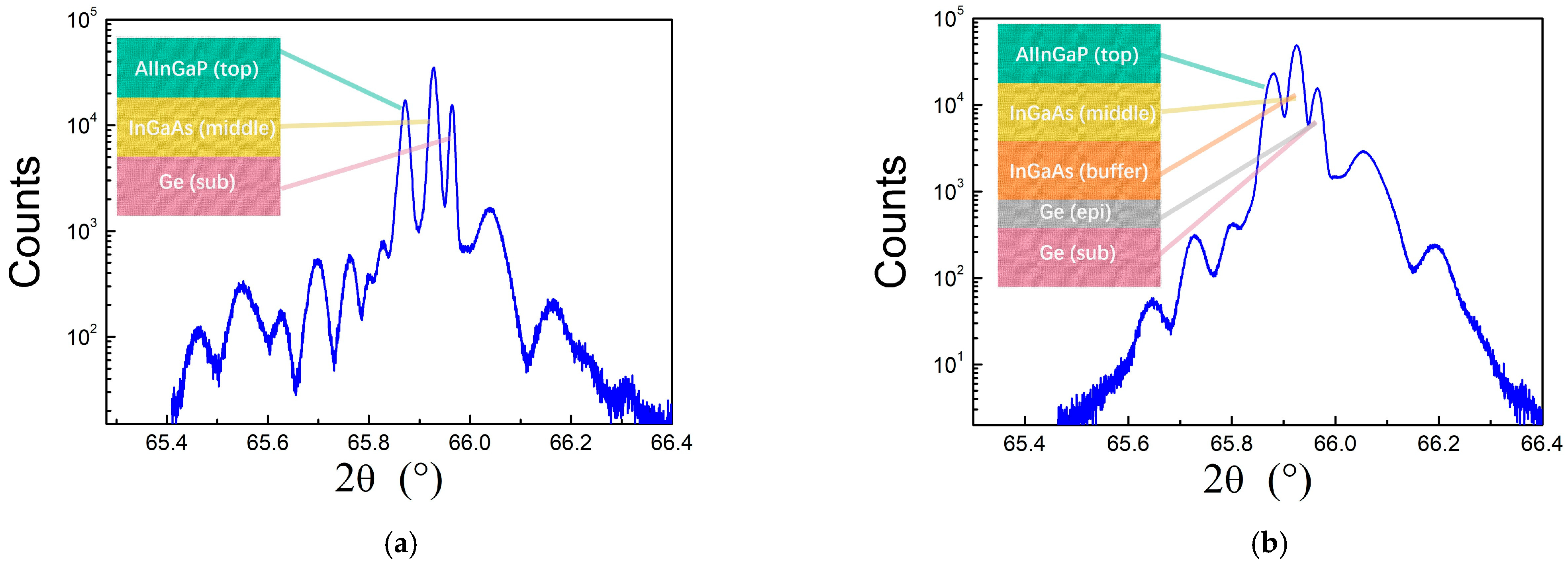
In Figure 5, HRXRD characterization of the full 4J InGaP/GaAs/Ge/Ge cell structure is reported and compared with that of a reference 3J InGaP/GaAs/Ge structure, deposited in a growth chamber not contaminated by IV elements. It is easy to observe that the FWHM of Ge, InGaAs, and AlInGaP peaks undergoes a slight increase in the amount of diffuse scattering. This experimental evidence can be reasonably ascribed to the introduction of the Ge-epy layer and InGaAs buffer layer in the 3J structure, and a consequent higher layer roughness, rather than a degradation of “bulk” crystalline perfection.

3.2. 4J InGaP/GaAs/Ge/Ge Device Optoelectronic Characterization Results and Discussion

Since the 4J device is a three-terminal device formed by two parts: a 3J InGaP/InGAs/Ge–1 upper cell and a Ge–2 bottom one, a 4J full characterization is accomplished by applying different loads on the two cell parts, as reported in Figure 6.
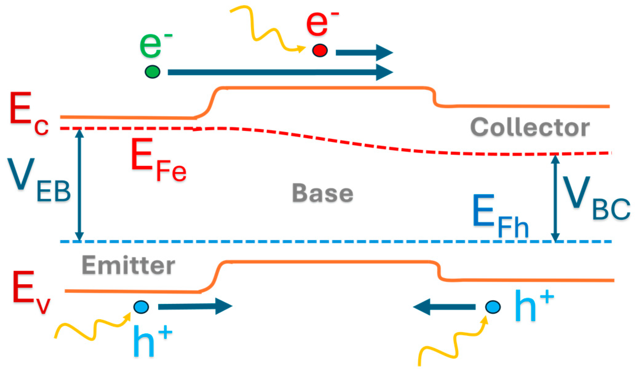
Figure 7a shows that when the 3J and Ge–2 part of the 4J device are kept in short circuit condition (both devices with electrical connection (2)), the EQE of the Ge–1 sub-cell and Ge–2 sub-cell are quite different from each other, since most of the light absorption takes place in the Ge–1 sub-cell, giving the Ge–2 sub-cell a typical “triangular shaped” EQE (curve blue in Figure 7a). However, as soon as a voltage appears on the 3J part of the 4J device, because, for example, the 3J cell is maintained in an open circuit condition, the EQE of the Ge–2 sub-cell changes drastically in intensity and shape (green curve in Figure 7a). Correspondingly, the I–V curve of the Ge–2 sub-cell, reported in Figure 7b, has an increasing short circuit and power values, as the 3J part of the 4J device changes its electrical connections from short circuit to open circuit, passing through the MPP value. This transfer of power is due to the transistor effect, i.e., the injection, by voltage, of carriers from the emitter to the base, and then to the collector. Since the collector is the n+ side of the Ge–2 junction, these carriers add to the carriers generated by light in the Ge–2 sub-cell, producing a higher EQE and PV power. For a better understanding of the transport across the transistor-like structure, a schematic of the band diagram of the Ge–1/Ge–2 sub-cell is reported in Figure 8.
In Figure 9, the external quantum efficiency and current voltage characterizations on the upper 3J and bottom Ge–2 cells are reported.
Once the Ge–2 sub-cell terminals are switched from short circuit to open circuit conditions, only a small increase in EQE is found for the Ge–1 sub-cell, because the reverse process of injection of carriers from the collector to the emitter is driven by a lower voltage of the Ge–2 sub-cell, and because the short circuit current of the Ge-1 sub-cell already starts at a higher value.
Eventually, the I–V curve of the 3J part of the 4J device does not change as the Ge–2 sub-cell terminals are switched from the short circuit to the open circuit condition. Since the limiting current in the 3J part is the top cell current, any increase in the Ge–1 sub-cell current due to the carrier injected from the collector to the emitter cannot be seen in the I–V characteristic.
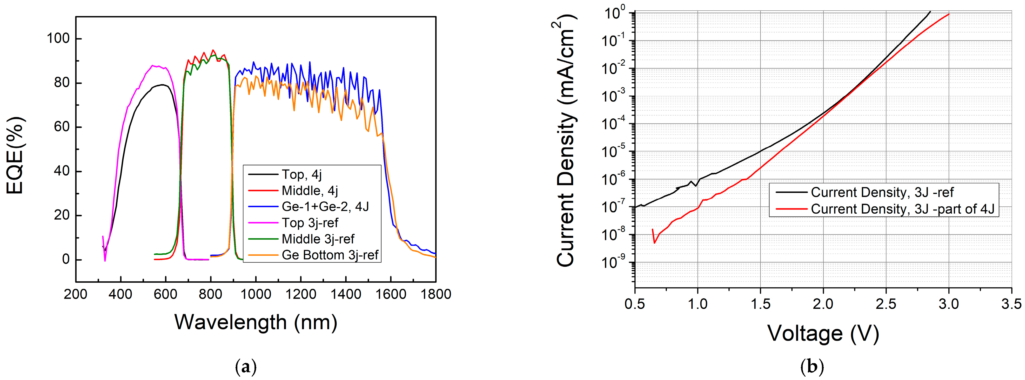
In Figure 9, the EQE and the dark current of the 3J part of the 4J device and of the reference 3J cell, whose structure has been deposited in a growth chamber not contaminated by I–V elements, are compared.
By considering the 3J part and the Ge–2 part of the 4J device in the short circuit condition (connection (2)), the sum of the Ge–1 and Ge–2 EQEs gives rise to the blue curve reported in Figure 9a. By comparing this curve with the EQE curve of the bottom Ge sub-cell of the 3J reference device (orange curve), we can conclude that the near-infrared spectrum is more efficiently captured by the 4J device with respect to the 3J reference one. The EQE of the AlInGaP top cell of the 4J device is, on the other hand, a little lower than the EQE of the top cell of the 3J reference device. We can exclude that this reduction is due to cross-contamination effects for the following three reasons: (i) the underlying InGaAs sub-cell of the 4J device shows EQE values a bit higher than those of the InGaAs sub-cell of the 3J reference device; if we had cross-contamination effects in the AlInGaP top cell, this effect should have been more marked in the underlaying InGaAs sub-cell, which is closer to the epitaxial Ge layers, then its EQE curve would be more pronouncedly reduced; (ii) tunnel diodes, whose peak currents are extremely sensitive to any doping compensation, have been verified to work correctly up to 500 suns concentration; (iii) the dark current, which is sensitive to carrier recombination in the pn junction, is lower in the 3J part of the 4J device with respect to the 3J reference one (see Figure 9b). Ge, as an n-type dopant, could compensate p-type dopants at the depletion region edge of III–Vs junctions. Compensation would have lowered the net doping, widened the depletion region, and enhanced the recombination rates. Compensation could also have introduced deep-level traps, which would have increased carrier recombination. We can simply explain the slight top cell EQE reduction in the 4J device because of the use of a thicker top cell emitter [18]. A thicker emitter has been deposited with the aim of reducing series resistance, as the front contact was realized only with a front busbar. As a drawback, we achieved an increased carrier recombination at the interface between the top cell emitter and window layer, which reduced the EQE values.
Therefore, by considering equal emitter top cell thickness, we can conclude that the 3J part of the 4J device performs like the 3J ref device realized in a MOVPE chamber free of group IV contamination: this demonstrates that the cross-contamination problem among Ge and III–Vs elements can be overcome to realize MJ solar cell structures in the same MOVPE growth chamber and in the same deposition run.
In Table 1 and Table 2, the electrical characterizations carried out on the 3J part and Ge-2 part of the 4J device are reported.
By considering that the functional 4J device has neither the structure nor the manufacturing process optimized, the electrical data are quite encouraging. By depositing a front grid instead of a big busbar, it would be possible to increase the FF to 87%, and, at the same time, the emitter thickness could be reduced and the top cell limiting current density could be increased by 1 mA/cm2 to reach a value of 13.7 mA/cm2. The ratio active area/total area of the functional 4J device is 0.5 because of the use of a big front busbar, while in optimized devices, this ratio can reach a higher value, typically 0.98, which would increase the Voc from 2.41 V to 2.42 V. Bringing together these improvements, the 3J part of the 4J device could potentially reach a conversion efficiency of 30%. Further improvements could be obtained by optimizing the top cell structure, mainly to raise the Voc value, which can reach values higher than 2.5 V in InGaP/InGaAs/Ge devices [19].
As far as the Ge–2 sub-cell is concerned, we must emphasize that the intermediate contact has been deposited directly on the Ge p-type layer without introducing any passivation techniques to reduce the minority carrier recombination [20]. By improving the manufacturing process, we could obtain higher Voc and therefore an increase in the conversion efficiency for this part of the 4J device. Nevertheless, when the 3J part of the 4J device is in MPP condition, the Ge-2 sub-cell reaches an efficiency value of 1.4% (under AM1.5d-ASTM-G173-3 spectrum), which is near to the theoretical modeled value of 1.5% reported by Aiken in [7] in InGaP/GaAs/Ge–1/Ge–2 solar cells, by considering a top-Ge–1 sub-cell 0.7 µm thick, connected via a tunnel diode to the bottom Ge–2 one, under AM0 spectrum.
In the proposed 4J cell, the advantage of the Ge–1/Ge–2 solar cell part with a transistor-like structure is not only the possibility of eliminating the tunnel diode, which reduces the MOVPE growth time, cell’s complexity, and light absorption in Ge–2 sub-cell, but also the opportunity of transferring current from the top Ge–1 junction to the bottom Ge–2 one, which allow for increasing the short circuit current of the bottom Ge–2 sub-cell and reducing, at the same time, the current mismatch in the top 3J InGaP/InGaAs/Ge structure.

4. Conclusions

Performance modeling of a 4-junction InGaP/InGaAs/Ge/Ge solar cell was developed over 25 years ago. In this 4J architecture, the two bottom Ge sub-cells were connected via a tunnel diode. Such MJ structures had not found realization until now, because the integration of IV elements with III–Vs for realizing these devices required two different types of growth equipment. The necessity of using dual equipment undermined the cost-effectiveness of monolithic multijunction designs.
In this contribution, we have presented the first demonstration of a 4J InGaP/GaAs/Ge/Ge functional device, with all layers sequentially deposited in the same MOVPE growth chamber and in the same deposition run.
The key elements that allowed us to overcome the cross-contamination among III–V and IV elements are related to the modification of the MOVPE reactor chamber, the selection of proper growth conditions, and proper device polarity and architecture.
A quartz plate was added to the graphite susceptor to reduce unwanted deposition in the central zone of the MOVPE growth chamber, as it remains cooler than the susceptor. Additionally, a new triple gas injector was developed, improving precursor utilization and enabling lower growth temperatures.
Thermal decoupling between the reactor ceiling and its cooling plate further minimized parasitic deposition. These changes allowed for optimized growth conditions for both epitaxial germanium and III–V materials, including lower temperatures and higher growth rates, while maintaining good layer morphology.
Buffer layers were also applied to reduce the Ge memory effect in III–V layers. The growth strategy, initially applied at the material and single-junction level, was successfully extended to multi-junction device deposition.
Selecting proper cell polarity has been important to exploit the cross-contamination between III–V and group IV elements, where it could not be completely avoided. Arsenic contamination has been exploited in the first phase of Ge nucleation, while Ge contamination allows for maintaining the cell polarity of the InGaAs buffer deposited between the epitaxial Ge and subsequent III–V layers.
The 4J device features novel architecture, with a third terminal inserted between the two Ge junctions, to avoid the tunnel diode connection, and the possibility to exploit a Ge n–p–n transistor-like structure for a power transfer between the two Ge bottom junctions, thus eliminating the current mismatch in the upper 3J InGaP/GaAs/Ge.
To demonstrate that cross-contamination between III–Vs and IV can be controlled and even exploited in the MOVPE reactor, the EQE and the dark I–V curves of a 4J InGaP/GaAs/Ge/Ge functional device have been compared with those of a 3J InGaP/GaAs/Ge one deposited in a clean MOVPE reactor chamber.
The electrical data show that by introducing realistic improvements, the 3J part of the 4J device could potentially reach a conversion efficiency comparable to state-of-the-art 3J InGaP/GaAs/Ge devices. By considering the extra Ge–2 junction of the 4J device, we can further consider adding an absolute efficiency increment of 1.4%, which almost agrees with the performance modeling and leads to the expected advantage of the 4J InGaP/GaAs/Ge/Ge device with respect to the 3J InGaP/GaAs/Ge one. This efficiency advantage can be increased by introducing passivation techniques for intermediate contact to reduce the minority carrier recombination.
To date, the use of an epitaxial Ge n–p–n transistor-like structure in an MJ device has never been reported. This structure is particularly intriguing because Germanium possesses the unique property of a direct bandgap and an indirect bandgap, where the former enables substantial light absorption and carrier generation even with layers a few microns thick. Additionally, the diffusion length in the p-type Ge base is approximately ten times greater than this thickness value, allowing for efficient carrier transfer from the emitter to the collector. This minimizes recombination within the base—achieving a true transistor effect—while maintaining excellent external quantum efficiency and reasonable epitaxial growth time. An epitaxial Si n–p–n transistor would not be convenient, since silicon requires 100 µm thick layers to achieve reasonable light absorption. When considering III–V semiconductors such as GaAs, due to their very high absorption coefficient, a much thinner epitaxial base layer could be used compared to what is required for Ge. However, since the diffusion length in p-type GaAs bases can be typically around 5–6 microns [21], exploiting the transistor effect would require a very thin base layer—potentially as thin as 0.5 µm—to ensure efficient carrier transfer from the emitter to the collector. As a result, the external quantum efficiency of the base would be significantly reduced, as already reported, for example, by considering an AlGaAs/GaAs BJT solar cell in [22].
It is worthwhile pointing out that most publications on bipolar junction transistor (BJT) solar cells mainly report about emitter and base regions, which are made of wide bandgap semiconductors, while the collector is made of low-bandgap material (tandem cells or heterojunction BJT cells). The BJT tandem solar cell efficiency is thus maximized by reducing to zero the emitter/base injection efficiency, i.e., by inhibiting the transistor effect [23,24,25]. In such devices, avoiding carrier injections from emitter to collector, when the base mobility value is very high, is important to preserve the voltage difference between the top and bottom cells, which have different bandgaps. In a homojunction transistor-like structure, the top and bottom sub-cells have the same bandgap; therefore, only a small voltage difference sets up between them in the MPP condition, and this voltage difference can be exploited for increasing the photocurrent of the bottom sub-cell, which suffers from the light absorption produced in the top one. The power increase of the bottom cell is accompanied by a power reduction of the top cell, but this phenomenon is intended to reduce the current mismatch in the upper part of the MJ device.
Despite there being slight efficiency increase with the 4J InGaP/GaAs/Ge/Ge device with respect to the 3J InGaP/GaAs/Ge one, the achievements obtained in this research pave the way to fully exploit the bandgap engineering possibilities offered by the monolithic integration of III–V and IV compounds, bringing new motivation in pursuing the realization of lower cost and more efficient all-MOVPE-grown, lattice-matched MJ solar structures, like 5-junction AlInGaP/AlInGaAs/InGaAs/Ge/Ge solar cells or those that can be realized by combining III–V with SiGeSn [26].

Author Contributions

Conceptualization, G.T.; methodology, G.T.; HR-XRD characterization, N.A. and E.A.; EQE and I–V characterization, F.T., M.V.I., A.M. and E.C.; MOVPE growth and in situ characterization, G.T. and M.C.; device manufacturing, F.A., E.A. and N.A.; writing—original draft preparation, G.T.; review and editing, all authors. All authors have read and agreed to the published version of the manuscript.

Funding

The first stage of the research started by awarding two European projects: in FP7, the APOLLON project, grant agreement N. 213514, and in H2020, the CPVMatch project, grant agreement N.640873. The work presented here on the realization of the 4J InGaP/InGaAs/Ga/Ge functional device has been financed by Research Fund for the Italian Electrical System under the Three-Year Research Plan 2025–2027 (DM MASE n. 388, 06.11.2024), in compliance with the Decree of 12 April 2024.

Data Availability Statement

The data presented in this study are available on request from the corresponding author.

Acknowledgments

This work has required the support of several researchers over the 18 years needed to achieve the final 4J presented results. We would like to thank Giovanni Abagnale, Cristina Chemelli, Alessio Martinelli, Tino Boni, Filippo Farina, and Marina Cornelli. Particular thanks to D. Schmitz and B. Schineller of AIXTRON, who allowed the implementation of the MOVPE hardware modifications necessary to optimize the growth and reduce cross-doping.

Conflicts of Interest

The authors declare no conflicts of interest. The funders had no role in the design of the study; in the collection, analyses, or interpretation of data; in the writing of the manuscript; or in the decision to publish the results.

Abbreviations

The following abbreviations are used in this manuscript:
EQEExternal quantum efficiency
MOVPEMetalorganic vapor phase epitaxy
FFFill factor
I–VCurrent-voltage
JscShort circuit current density
MJMultijunction
MPPMaximum power point
VocOpen circuit voltage
EcEnergy of the conduction band
EvEnergy of the valence band
EFeQuasi Fermi level of electrons
EFhQuasi Fermi level of halls
VEBVoltage of the emitter/base junction
VBCVoltage of the base/collector junction

References

  1. Shockley, W.; Queisser, H.J. Detailed balance limit of efficiency of p-n junction solar cells. J. Appl. Phys. 1961, 32, 510–519. [Google Scholar] [CrossRef]
  2. Kurtz, S.R.; Myers, D.; Olson, J.M.; Kurtz, S.R. Projected Performance of Three-and Four-Junction Devices Using GaAs and GaInP. In Proceedings of the Conference Record of the Twenty Sixth IEEE Photovoltaic Specialists Conference—1997, Anaheim, CA, USA, 29 September–3 October 1997. [Google Scholar]
  3. Kujofsa, T.; Ayers, J.E. Equilibrium Lattice Relaxation and Misfit Dislocations in Step-Graded InxGa1−xAs/GaAs (001) and InxAl1−xAs/GaAs (001) Metamorphic Buffer Layers. J. Electron. Mater. 2016, 45, 2831–2836. [Google Scholar] [CrossRef]
  4. Geisz, J.F.; France, R.M.; Schulte, K.L.; Steiner, M.A.; Norman, A.G.; Guthrey, H.L.; Young, M.R.; Song, T. Six-junction III–V solar cells with 47.1% conversion efficiency under 143 Suns concentration. Nat. Energy 2020, 5, 326–335. [Google Scholar] [CrossRef]
  5. Tanabe, K. Semiconductor Wafer Bonding for Solar Cell Applications: A Review. Adv. Energy Sustain. Res. 2023, 4, 2300073. [Google Scholar] [CrossRef]
  6. Green, M.A.; Dunlop, E.D.; Yoshita, M.; Kopidakis, N.; Bothe, K.; Siefer, G.; Hao, X.; Jiang, J.Y. Solar Cell Efficiency Tables (Version 66). Prog. Photovolt. Res. Appl. 2025, 33, 795–810. [Google Scholar] [CrossRef]
  7. Aiken, D.J. InGaP/GaAs/Ge multi-junction solar cell efficiency improvements using epitaxial germanium. In Proceedings of the Conference Record of the IEEE Photovoltaic Specialists Conference, Anchorage, AK, USA, 15–22 September 2000; Institute of Electrical and Electronics Engineers Inc.: Piscataway, NJ, USA, 2000; pp. 994–997. [Google Scholar] [CrossRef]
  8. King, R.R.; Bhusari, D.; Larrabee, D.; Liu, X.-Q.; Rehder, E.; Edmondson, K.; Cotal, H.; Jones, R.K.; Ermer, J.H.; Fetzer, C.M.; et al. Solar cell generations over 40% efficiency. Prog. Photovolt. Res. Appl. 2012, 20, 801–815. [Google Scholar] [CrossRef]
  9. Roucka, R.; Clark, A.; Landini, B. Si-Ge-Sn alloys with 1.0 eV gap for CPV multijunction solar cells. In Proceedings of the 11th International Conference on Concentrator Photovoltaic Systems: CPV-11, Aix-les-Bains, France, 13–15 April 2015; American Institute of Physics Inc.: College Park, MD, USA, 2015. [Google Scholar] [CrossRef]
  10. Wilson, T.; Thomas, T.; Führer, M.; Ekins-Daukes, N.J.; Roucka, R.; Clark, A.; Johnson, A.; Hoffman, R.J.; Begarney, D. Single and multi-junction solar cells utilizing a 1.0 eV SiGeSn junction. In Proceedings of the 12th International Conference on Concentrator Photovoltaic Systems (CPV-12), Freiburg, Germany, 25–27 April 2016; American Institute of Physics Inc.: College Park, MD, USA, 2016. [Google Scholar] [CrossRef]
  11. Caño, P.; Hinojosa, M.; Nguyen, H.; Morgan, A.; Marrón, D.F.; García, I.; Johnson, A.; Rey-Stolle, I. Hybrid III-V/SiGe solar cells grown on Si substrates through reverse graded buffers. Sol. Energy Mater. Sol. Cells 2020, 205, 110246. [Google Scholar] [CrossRef]
  12. Timò, G.; Calicchio, M.; Abagnale, G.; Armani, N.; Achilli, E.; Cornelli, M.; Annoni, F.; Schineller, B.; Andreani, L.C. Study of the cross-influence between iii-v and iv elements deposited in the same movpe growth chamber. Materials 2021, 14, 1066. [Google Scholar] [CrossRef] [PubMed]
  13. Martin, C.; Dauelsberg, M.; Protzmann, H.; Boyd, A.R.; Thrush, E.J.; Heuken, M.; Talalaev, R.A.; Yakovlev, E.V.; Kondratyev, A.V. Modelling of group-III nitride MOVPE in the closed coupled showerhead reactor and Planetary Reactor®. J. Cryst. Growth 2007, 303, 318–322. [Google Scholar] [CrossRef]
  14. Welser, E.; Guter, W.; Wekkeli, A.; Dimroth, F. Memory effect of Ge in III–V semiconductors. J. Cryst. Growth 2008, 310, 4799–4802. [Google Scholar] [CrossRef]
  15. Timò, G. A New Path to Combine III–V and IV Elements for High-Efficiency and Low-Cost Multi-Junction Solar Cells. Ph.D. Thesis, University of Pavia, Pavia, Italy, 2022. Available online: https://iris.unipv.it/retrieve/e1f104fd-1e9b-8c6e-e053-1005fe0aa0dd/Tesi%20Timo_def.pdf (accessed on 28 August 2025).
  16. Timò, G.; Calicchio, M.; Armani, N.; Achilli, E.; Cornelli, M.; Annoni, F.; Trespidi, F.; Imperatore, M.; Malvisi, E. First demonstration of a three terminals-quadruple junction InGaP/InGaAs/Ge/T/Ge solar cell—All MOVPE grown-exploiting the transistor effect. In Proceedings of the 53rd IEEE Photovoltaic Specialist Conference, Montreal, QC, USA, 8–13 June 2025. [Google Scholar] [CrossRef]
  17. Breiland, W.G.; Killeen, K.P. A virtual interface method for extracting growth rates and high temperature optical constants from thin semiconductor films using in situ normal incidence reflectance. J. Appl. Phys. 1995, 78, 6726–6736. [Google Scholar] [CrossRef]
  18. Takamoto, T.; Ikeda, E.; Kurita, H.; Ohmori, M. Structural optimization for single junction InGaP solar cells. Sol. Energy Mater. Sol. Cells 1994, 35, 25–31. [Google Scholar] [CrossRef]
  19. Takamoto, T.; Kaneiwa, M.; Imaizumi, M.; Yamaguchi, M. InGaP/GaAs-based multijunction solar cells. Prog. Photovolt. Res. Appl. 2005, 13, 495–511. [Google Scholar] [CrossRef]
  20. Kurtz, S.R.; Olson, J.M.; Friedman, D.J.; Geisz, J.F.; Kibbler, A.E.; Bertness, K.A. Passivation of Interfaces in High-Efficiency Photovoltaic Devices. 1999. Available online: https://docs.nrel.gov/docs/fy99osti/26494.pdf (accessed on 29 August 2025).
  21. Niemeyer, M.; Ohlmann, J.; Walker, A.W.; Kleinschmidt, P.; Lang, R.; Hannappel, T.; Dimroth, F.; Lackner, D. Minority carrier diffusion length, lifetime and mobility in p-type GaAs and GaInAs. J. Appl. Phys. 2017, 122, 115702. [Google Scholar] [CrossRef]
  22. Gilberti, G. Multiterminal Solar Cells with Heterojunction-Bipolar Transistor Structure: Analysis and Design. Master’s Thesis, Politecnico Di Torino, Torin, Italy, 2019. Available online: http://webthesis.biblio.polito.it/id/eprint/11003 (accessed on 24 August 2025).
  23. Martí, A.; Luque, A. Three-terminal heterojunction bipolar transistor solar cell for high-efficiency photovoltaic conversion. Nat. Commun. 2015, 6, 6902. [Google Scholar] [CrossRef] [PubMed]
  24. Linares, P.G.; Antolín, E.; Martí, A. Novel heterojunction bipolar transistor architectures for the practical implementation of high-efficiency three-terminal solar cells. Sol. Energy Mater. Sol. Cells 2019, 194, 54–61. [Google Scholar] [CrossRef]
  25. Zhang, X.; Ang, Y.S.; Ye, Z.; Su, S.; Chen, J.; Ang, L.K. Three-terminal heterojunction bipolar transistor solar cells with non-ideal effects: Efficiency limit and parametric optimum selection. Energy Convers. Manag. 2019, 188, 112–119. [Google Scholar] [CrossRef]
  26. King, R.R.; Fetzer, C.; Chiu, P.; Rehder, E.; Edmondson, K.; Karam, N. (Invited) Group-IV Subcells in Multijunction Concentrator Solar Cells. ECS Trans. 2013, 50, 287–295. [Google Scholar] [CrossRef]
Figure 1. Key components of the MOVPE reactor chamber: (a) quartz plate in the center of a graphite susceptor. Green arrows show the gas flow coming from the gas injector and distributed radially over the susceptor; (b) ceiling and triple gas injector.
Crystals 15 00816 g001
Figure 2. (a) 4J cell’s structure; (b) plan view of the realized 4J device. The device has a busbar front contact (T), a busbar intermediate contact (M), and a bottom contact (B) distributed all over the back side device surface.
Crystals 15 00816 g002
Figure 3. (a) Reflectance curve at 405 nm and 950 nm, related to the 4J structure growth, (b) surface morphology captured at the optical microscope at 1000× magnification. Oscillations at 950 nm reflectance were used for growth rate computation [17].
Crystals 15 00816 g003
Figure 4. (a) Temperature profile and (b) curvature profile, both measured in situ during the 4J cell’s structure growth. Negative curvature values lead to a convex wafer, while positive curvature values lead to concave wafers. TD stands for “tunnel diode”.
Crystals 15 00816 g004
Figure 5. (a) HRXRD analysis of the 3J InGaP/InGaAs/Ge reference structure deposited in a growth chamber not contaminated by group IV elements; (b) HRXRD analysis of the 3J part InGaP/InGaAs/Ge structure of the 4J device. The main thick layers of the cell structures are depicted to put in evidence the main structural differences between the two devices.
Crystals 15 00816 g005
Figure 6. Different electrical connections for the characterization of the 4J device: the upper 3J cell can be characterized by considering the Ge–2 cell with its two terminals in (1), open circuit condition, (2) short circuit condition, or (3) maximum power point (MPP), i.e., connecting the terminal to an external load that maximizes power extraction. The same electrical connections are considered for the 3J cell when the Ge–2 cell performances are measured.
Crystals 15 00816 g006
Figure 7. (a) External quantum efficiency and (b) current-voltage (I–V) characteristics of the 3J and Ge-2 part of the 4J device in the different terminals’ configurations, indicated by numbers in the brackets, according to Figure 6.
Crystals 15 00816 g007
Figure 8. Schematic of the band diagram of Ge–1/Ge–2 transistor-like structure. It is shown how the electrons (e green) injected by voltage from the top Ge–1 junction to the collector add to the electrons generated (e red) by light (represented by orange arrows) in the bottom Ge–2 junction to produce an overall increase in the EQE of the bottom Ge–2 cell. The light-generated positive charges (h+) are collected in the base. A gradient in the quasi-Fermi level of electrons (EFe) exists to sustain the electron diffusion current.
Crystals 15 00816 g008
Figure 9. (a) External quantum efficiency comparison between the 3J part InGaP/InGaAs/Ge of the 4J device and of the reference 3J structure InGaP/InGaAs/Ge; (b) dark I–V comparison between the 3J part of the 4J device and the reference 3J structure.
Crystals 15 00816 g009
Table 1. Electrical data for the 3J part of the 4J device, regardless of the electrical connections of the Ge–2 part. Measurement performed under solar simulator with AM1.5d-ASTM-G173-3 spectrum.
Jsc (mA/cm2)Voc (V)FF (%)Efficiency (%) 1
12.72.418024.5
1 Device area = 3.657 mm2.
Table 2. Electrical data for the Ge–2 part of the 4J device, considering the electrical connections of the 3J part in open circuit and MPP. Measurement performed under solar simulator with AM1.5d-ASTM-G173-3 spectrum.
Jsc (mA/cm2)Voc (V)FF (%)Efficiency (%) 13J Electrical Connection
20.50.18156.32.1Open circuit
13.90.17158.71.4MPP
1 Device area = 4.217 mm2.
Disclaimer/Publisher’s Note: The statements, opinions and data contained in all publications are solely those of the individual author(s) and contributor(s) and not of MDPI and/or the editor(s). MDPI and/or the editor(s) disclaim responsibility for any injury to people or property resulting from any ideas, methods, instructions or products referred to in the content.