Article

In Situ TEM Investigation of Dislocation-Mediated Deformation in Eutectic Fe36Ni18Mn33Al13 Alloy

by
Fanling Meng
*,
Jiaqi Zhu
*,
Heyi Wang
,
Jiayi Li
and
Yang Lu
Department of Mechanical Engineering, The University of Hong Kong, Pokfulam, Hong Kong SAR, China
*
Authors to whom correspondence should be addressed.
Crystals 2025, 15(9), 792; https://doi.org/10.3390/cryst15090792 (registering DOI)
Submission received: 20 July 2025 / Revised: 28 August 2025 / Accepted: 1 September 2025 / Published: 5 September 2025

Abstract

Eutectic FeNiMnAl multi-principal element alloys exhibit exceptional strength–ductility synergy, yet their dynamic deformation mechanisms remain poorly characterized. This study employs in situ transmission electron microscopy to investigate dislocation-mediated plasticity in Fe36Ni18Mn33Al13—a lamellar FCC/B2 alloy with balanced properties. Real-time observations under tensile loading (at a strain rate of 0.1 μm/s, with a resolution of ~2 nm) reveal coordinated dislocation planar glide, cross-slip at obstacles, and pile-up formation at phase boundaries. Planar slip bands dominate early deformation, while cross-slip facilitates barrier bypass and strain homogenization. The coarse microstructure of Fe36Ni18Mn33Al13 promotes extensive dislocation storage, reducing strength but enhancing ductility compared to finer FeNiMnAl variants.

1. Introduction

Multi-principal element alloys (MPEAs), including high-entropy alloys (HEAs), have garnered significant attention due to their exceptional mechanical properties, such as high strength, corrosion resistance, and thermal stability, making them ideal candidates for extreme environments [1,2]. Among these, FeNiMnAl-based alloys exhibit a unique nanoscale microstructure that enables a remarkable synergy between strength and ductility [3,4]. Three distinct microstructural types are observed in FeNiMnAl-based alloys [5,6]: ultrafine B2/L21 phases (5–10 nm widths), coarse B2/BCC phases (~50 nm widths), and fine lamellar FCC/B2 structures (65–85 nm widths), where decreasing phase widths correlate with increased hardness [7]. For instance, Fe30Ni20Mn25Al25 exhibits a hardness of ~500 HV due to its refined structure [8], while coarser microstructures like that in Fe30Ni20Mn35Al15 show reduced hardness (~310 HV) but enhanced ductility [4]. The lamellar-structured alloys typically feature alternating face-centered cubic (FCC) and ordered body-centered cubic ordered (B2) phases, where the FCC matrix accommodates plastic strain while the B2 phase acts as a reinforcing obstacle to dislocation motion during deformation [7].
The alloy Fe36Ni18Mn33Al13 achieves an exceptional balance of yield strength (463 MPa) and ductility (26.1% elongation) at room temperature, outperforming counterparts like Fe30Ni20Mn35Al15 (6.5% elongation) [4,9]. This performance originates from its optimized microstructure: an FCC phase fraction of ~85% with lamellar widths of ~1560 nm, and B2 phase widths of ~410 nm, facilitating efficient strain accommodation [9]. Deformation in these alloys is governed by phase-specific mechanisms, where the FCC phase accommodates plasticity through dislocation glide on {111} planes via a/2 〈110〉 systems, while the B2 phase impedes dislocation motion, acting as an obstacle [4,7,10]. Post-mortem transmission electron microscopy (TEM) studies confirm dislocation pile-ups in FCC lamellar phase near phase boundaries, which could generate local stress concentrations that may initiate microcracks [7]. This aligns with classical fracture mechanics models where dislocation accumulation at barriers (e.g., phase interfaces) promotes crack nucleation by exceeding local cohesive strength [11,12,13]. However, dynamic processes governing dislocation nucleation, cross-slip, and interface interactions in FeNiMnAl alloys remain elusive due to limitations in post-mortem characterization.
Advancements in in situ TEM straining have revolutionized the study of deformation mechanics, enabling real-time observation of key mechanisms, such as dislocation avalanches and cross-slip, superdislocation glide and anti-phase boundary formation, and twinning-mediated plasticity in metastable HEAs [14,15,16]. Despite these advances, in situ investigations of FeNiMnAl MPEAs remain scarce, limiting understanding of how coordinated dislocation motion enhances ductility. The role of FCC/B2 interfaces in modulating dislocation transmission versus emission remains unexplored.
Here, we integrate in situ TEM straining with microstructural analysis to elucidate dislocation-mediated plasticity in Fe36Ni18Mn33Al13. By capturing dynamic processes such as dislocation coordinated glide and interface interactions, this work addresses a gap in FeNiMnAl MPEA deformation mechanics, providing foundational insights for designing next-generation alloys with superior strength–ductility trade-offs.

2. Experiments

The alloy with a target composition of Fe36Ni18Mn33Al13 was synthesized from elemental powders of Fe, Ni, Mn, and Al, each with a purity level of at least 99.8%. To account for manganese evaporation during processing, an extra 5 wt% Mn was incorporated into the initial mixture. Arc melting was conducted in a copper crucible cooled by water, under a protective argon gas environment. To achieve compositional uniformity, the ingots were inverted and remelted twice following the first fusion. Given the compact dimensions of the cast ingot, cooling occurred uniformly without directional bias. For phase identification, X-ray diffraction (XRD) analysis was carried out on polished samples using a Rigaku D/Max 2000 (The Woodlands, TX, USA) instrument with Cu Kα radiation at 40 kV and 300 mA. Scans covered a 2θ range from 20° to 120° in 0.02° increments, with each step held for 1 s, resulting in a total duration of approximately 1.5 h per scan.
Scanning electron microscopy (SEM) specimens were prepared by sequential polishing with progressively finer silicon carbide papers and a final 0.3 μm alumina suspension to attain a reflective surface. Etching involved a brief immersion in 4% nitric acid (approximately 5 s), followed by water rinsing. Observations were made in an FEI XL-30 (Hillsboro, OR, USA) field emission gun SEM at an accelerating voltage of 15 kV. The SEM images were processed using software ImageJ (Version 1.54p) to calculate lamellar width of the two phases, which was calculated by measuring the distance between intersections after drawing lines across the phases. The final value of the spacing width is an average of at least 20 measurements per phase from multiple images. Fracture surfaces from tensile tests were also imaged using this equipment.
Vickers hardness measurements employed a Leitz MINIload (Grand Rapids, MI, USA) tester. Samples were embedded in phenolic resin, polished to a mirror-like finish with 0.3 μm alumina, and tested under a 1.96 N (200 g) load with a 20-s dwell time. Reported hardness values represent averages from no fewer than five indentations. In order to determine the hardness of individual phases in Fe30Ni20Mn35Al15, a Hysitron Ubi-1 (Billerica, MA, USA) scanning quasi-static nanoindentor was used. The typical indent size was ∼1 μm.
Tensile testing utilized an MTS mechanical testing system. Dog-bone-shaped specimens featured a 10 mm gauge length and 1.27 mm thickness. Surface preparation included polishing with silicon carbide papers and 0.3 μm alumina to eliminate defects. Tests ran at an initial strain rate of 5 × 10⁻⁴ s−1 under ambient conditions. Gauge length changes, measured via optical microscopy before and after testing, determined fracture elongation.
Transmission electron microscopy (TEM) samples were prepared from disks roughly 3 mm in diameter and 100 μm thick. Electropolishing in a 25% nitric acid-methanol solution at 253 K used a Struers Tenupol 5 unit (Tallahassee, FL, USA), operating at approximately 11 V and 100 mA. Post-polishing cleaning involved three cycles of alternating ethanol and methanol washes, ending with a methanol rinse. Thin foils were analyzed in an FEI Tecnai F20 FEG TEM (Hillsboro, OR, USA) equipped with energy-dispersive X-ray spectroscopy (EDS) at 200 kV.
For in situ straining studies in the TEM, specimens were machined into rectangular shapes with perforated ends [17]. The central region was thinned to electron transparency using identical electropolishing conditions as for standard TEM samples. Residual contaminants were removed by ion milling at 4 kV for about 5 min. Mounted in a single-tilt holder with ends secured by screws, deformation was induced at a rate of 0.1 μm/s within a Tecnai F20 TEM (Hillsboro, OR, USA).

3. Results and Discussion

3.1. Phase Identification and Lamellar Microstructure

XRD analysis (Figure 1a) confirms the exclusive presence of B2 and FCC phases in the Fe36Ni18Mn33Al13 alloy, consistent with the dual-phase paradigm observed in FeNiMnAl systems [18]. Secondary electron (SE) SEM images (Figure 1b,c) reveal a well-defined lamellar microstructure formed during arc melting, with grain boundaries delineating grains of ~300 μm. Within individual grains, alternating FCC (dark contrast) and B2 (light contrast) lamellae exhibit preferential alignment. Critically, the FCC phase width (~1500 nm) and B2 phase width (~400 nm) significantly exceed those reported in prior studies (e.g., Fe30Ni20Mn35Al15: FCC ~500 nm, B2 ~200 nm) [3,4,7,9,10]. This microstructural coarsening correlates with reduced Al content (13 at.% vs. 15 at.%), which elevates the FCC phase fraction to ~85% has a significant impact on mechanical properties of the alloy [9,19].
Figure 2 shows a bright-field (BF) TEM image in (a) and corresponding convergent beam electron diffraction (CBED) pattern in (b) to confirm the presence of B2 phase. The chemical composition of the as-cast alloy, determined by EDS analysis in TEM, was measured to be Fe36.5Mn17.8Ni33.6Al12.6, based on an average of five measurements taken across the sample. The results indicate that the composition of the arc-melted ingot closely matches the targeted nominal composition for each element. The weak {100} superlattice diffraction spots confirm the phase’s crystallographic distinction from conventional BCC. The {100} diffraction spots are extinct in conventional BCC crystals and thus invisible in the diffraction patterns. As seen in Figure 2c, the B2 structure is an ordered derivative of BCC with distinct elements at body-center and corner sites. B2 structure was found in many alloys and proved to be critical to the mechanical properties and deformation mechanisms of those alloys [4,7,20]. The occupancy of body-centered sites by Ni/Al and corner sites by Fe/Mn [21] governs deformation behavior. Nanoindentation studies quantify the B2 phase’s intrinsic hardness (~4.38 GPa) as markedly higher than the FCC phase (~2.72 GPa) [3]. This disparity underpins the B2 phase’s role as a barrier to dislocation glide in FCC lamellae during initial plastic deformation [7].

3.2. Mechanical Properties

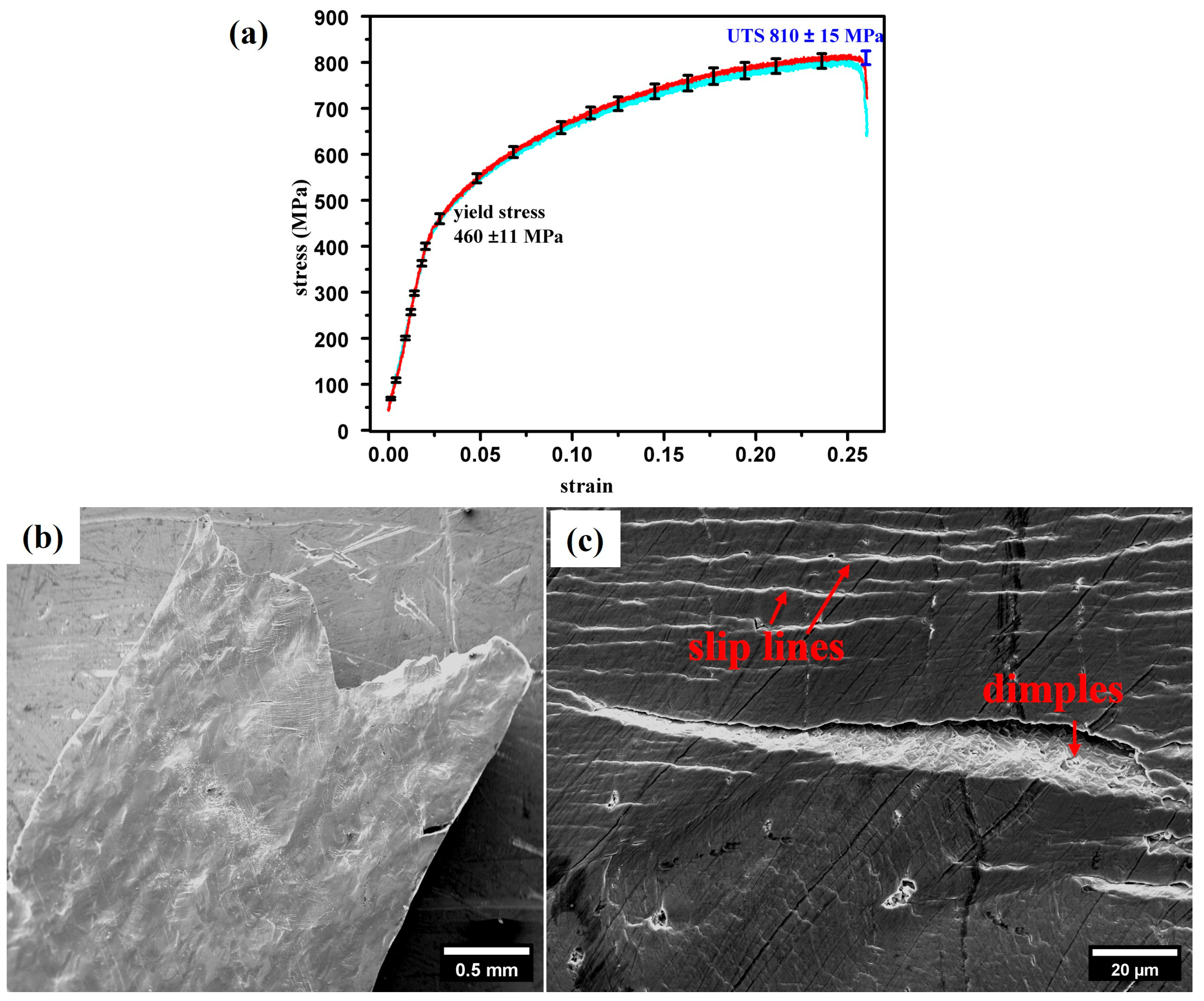
Based on the experimental data, the Vickers hardness of the Fe36Ni18Mn33Al13 alloy was measured as 208 ± 7 HV. From the average of five nanoindentation tests, the hardness was 3.4 ± 0.4 GPa for the B2 phase and 2.1 ± 0.3 GPa for the FCC phase, respectively. Five dog-bone specimens were tensile tested for the mechanical properties of the alloy. Figure 3a presents two representative tensile stress–strain curves, revealing an average elongation to fracture of 26 ± 0.8%, yield strength of 460 ± 11 MPa, and ultimate tensile strength of 810 ± 15 MPa. Compared to the well-studied as-cast Fe30Ni20Mn35Al15 alloy (hardness: 310 ± 15 HV, yield strength: 740 MPa) [4], the Fe36Ni18Mn33Al13 exhibits a clear reduction in strength but a significant enhancement in ductility (26% vs. 8%). This inverse relationship between strength and ductility aligns with the well-documented strength–ductility trade-off commonly observed in metallic materials [12]. NiAl-based alloys (e.g., Ni50Al20Fe30) show comparable trade-offs, where coarser microstructures (λ ≈ 2 μm) achieve elongations >20% but at lower yield strengths (~570 MPa), contrasting with nanostructured variants (λ ≈ 0.5 μm) that reach ~750 MPa but <10% elongation [11,22]. The underlying mechanism in the present alloy system is primarily attributed to microstructural coarsening, which directly impacts strength–ductility relationships. Yield strength (σy) adheres to a Hall–Petch-type relationship:
σy = σ0 + kλ−1/2
where λ is the FCC lamellar width, σ0 is lattice friction stress, and k is a constant [23]. Increased λ (e.g., ~1500 nm in Fe36Ni18Mn33Al13 vs. ~500 nm in Fe30Ni20Mn35Al15) diminishes Hall–Petch strengthening effect, reducing σy from 820 MPa to 460 MPa [9]. Conversely, ductility escalates from 6.5% to 26.1% due to: 1. Reduced constraint: Larger FCC lamellae accommodate greater dislocation pile-ups and plastic deformation before fracture initiation in the B2 phase, thereby enhancing ductility [9]; 2. Diminished environmental embrittlement: Coarser microstructures exhibit lower hydrogen susceptibility at low strain rates [3]. Specifically, the increased width of both the FCC and B2 lamellae in Fe36Ni18Mn33Al13 reduces the effectiveness of the hard B2 phase as a barrier to dislocation motion within the ductile FCC phase.
This microstructural dependence of mechanical properties is consistent with observations in other dual-phase alloys [11,22,24,25,26,27], where refined microstructures boost strength at the expense of ductility, while coarser structures exhibit the opposite trend. In Ti-Al alloys, refined lamellar spacings (e.g., 30–400 nm) enhance yield strength but suppress ductility by inhibiting deformation twinning and promoting cleavage fracture [24]. Maruyama et al. [26] demonstrated that yield strength in Ti-39.4 mol% Al adheres to a Hall–Petch relationship, with ductility decreasing from 12% to 5% as lamellar spacing is reduced from 10 μm to 0.5 μm. Pearlitic steels exhibit similar behavior, where interlamellar spacing refinement increases strength via dislocation confinement between cementite walls but reduces fracture strain due to suppressed plasticity. Hyzak and Bernstein reported that hardness in fully pearlitic steels scales with λ−1/2, with ductility declining below 5% for spacings <200 nm [27]. The specific composition shift (reduced Al content from 15 at. % to 13 at. %) in Fe36Ni18Mn33Al13 promotes this lamellar coarsening due to altered phase stability and diffusion kinetics during solidification, as confirmed in previous investigation [9], where it was demonstrated that decreasing Al content increases FCC phase fraction and lamellar spacing, directly correlating with reduced yield stress and enhanced elongation in FeNiMnAl alloys.
Figure 3b depicts the surface morphology adjacent to the fracture site of dog-bone-shaped tensile specimens following tensile tested to failure, alongside high-magnification micrographs revealing slip lines, microcracks and dimples at the crack surface in Figure 3c. These features signify substantial plastic deformation during tensile loading, consistent with the measured 26% elongation. The high density of slip lines indicates dislocation multiplication and cross-slip, contributing to strain hardening [28]. Slip traces often terminate at grain/phase boundaries (e.g., FCC/B2 interfaces), where dislocations pile up and induce stress concentration. This can initiate microcracks or activate secondary slip systems [15].
Microcracks typically nucleate at phase boundaries due to stress concentrations at FCC/B2 interfaces, leading to interfacial decohesion where brittle B2 phases fracture elastically while ductile FCC phases blunt crack propagation, as observed in FeNiMnAl alloys [7]. Additionally, slip-band intersections serve as nucleation sites due to high dislocation densities in dual-phase alloys [29]. Dimples on crack surfaces form through microvoid coalescence initiated at phase boundaries, with void growth under tensile stress culminating in dimple formation [12]. This aligns with previous finding of dimpled fracture in NiAl-Fe alloys to void nucleation at B2/FCC interfaces [11], while Wang et al. quantified dimple density in FeCoCrMnNi HEAs, linking it to dislocation-mediated void growth [30]. Fractography reveals ductile dimples in FCC regions, whereas B2 phases undergo cleavage-like fracture due to limited slip systems [4,31].

3.3. Deformation Mechanisms

The in situ TEM observations presented in Figure 4, Figure 5 and Figure 6 provide a comprehensive temporal analysis of dislocation dynamics in FCC phase under tensile deformation, revealing distinct stages of evolution from early slip activation to interface-mediated hardening. The dislocation density within the FCC lamellae was quantitatively determined to be approximately 1014 m−2, as extrapolated from TEM images. Due to the negligible dislocation content in the B2 phase, dislocation density estimation was deemed inapplicable. The study confirms plastic deformation localizes in FCC lamellae, while B2 lamellae remain elastic until high stress levels, acting as effective barriers to dislocation motion [4]. Figure 4 (extracted from Supplementary Material Movie 1) captures the initial response, where time-sequence bright-field (BF) TEM images (recorded at t0 and t0 + 3 s) illustrate the propagation of dislocations via planar slip. Specifically, slip bands develop as parallel stripe-like structures, demarcated by dashed lines (Figure 4a), indicating cooperative glide on primary slip planes. Concurrently, new dislocations emerge (marked as 0), as evidenced by the nucleation events in regions of high local stress. Furthermore, dislocations (e.g., labeled 2, 3, and 4) exhibit characteristic bowing morphology due to pinning at defect sites, resulting in curved configurations that reflect stress-induced elongation. These observations highlight the rapid activation of dislocation sources and their glide-dominated behavior in the early deformation stage [14].
Figure 5 (extracted from Supplementary Material Movie 2) elucidates progressive dislocation kinetics over an extended period (t0 to t0 + 12 s), emphasizing dynamic interactions and cross-slip mechanisms. The sequence reveals dislocation migration (e.g., dislocations 1, 2, and 3 traversing the field of view) and eventual disappearance, suggesting annihilation at obstacles or other dislocations. Notably, cross-slip events are visible, identified by abrupt changes in slip plane direction (indicated by red dashed lines), which facilitate dislocation bypass of barriers such as precipitates or phase boundaries [32]. This kinetic behavior demonstrates the transition from simple glide to more complex, multi-planar deformation, driven by increasing applied stress [33]. Additionally, dislocation multiplication (e.g., proliferation of dislocation 0, more details in Supplementary Material Movie 2) occurs under stress concentrations, underscoring the role of stress concentrations in generating secondary dislocations that amplify strain accommodation. Dislocations were frequently pinned by obstacles with leading dislocations escaping after initial obstruction, followed by rapid emission of subsequent dislocations [34].
Figure 6 (extracted from Supplementary Materials Movie 3 and 4) documents the culmination of deformation after prolonged loading (t0 + 45 s), where dislocations accumulate at phase boundaries, forming pile-up configurations. The dislocation pile-up lengths and the number of dislocations in a pile-up at FCC/B2 phase boundaries were quantified using in situ TEM images (Figure 4, Figure 5 and Figure 6). The average pile-up length was measured to be approximately ~2 μm, with each pile-up containing ~30 dislocations. The BF TEM images depict dislocation glide lines evolving into high-density clusters at interfaces (Figure 6h). This pile-up phenomenon arises from the impediment of dislocation motion by hard phase boundaries, leading to localized stress buildup. Prior events, such as cross-slip (visible in earlier frames), preceded at this stage, confirming that slip band interactions dominate the late deformation regime. Dislocations exhibited cross-slip at slip band intersections, transitioning from primary to conjugate slip planes, forming dislocation junctions and multipoles [34]. This cross-slip was rare during slip propagation but common at intersections, indicating localized softening.
The observed dislocation dynamics provide critical insights into the deformation mechanisms of the material, elucidating pathways for strain accommodation and strengthening. The planar slip and slip band formation in Figure 4 (e.g., dislocation propagation and bowing) signify the dominance of primary slip systems under low-to-moderate strains, which is consistent with behavior in FCC metals where stress concentrations at dislocation sources initiate glide [35]. The bowing morphology underscores the influence of pinning points (e.g., sessile dislocations or precipitates), generating long-range internal stresses that promote work hardening through dislocation entanglement. This aligns with Mughrabi’s model, where such structures store elastic energy, contributing to isotropic strengthening [36].
The cross-slip and dislocation multiplication events in Figure 5 and Figure 6 represent a key transition to multi-slip deformation, which enhances ductility by enabling strain distribution across multiple planes. For instance, the cross-slip processes facilitate dislocation escape from obstacles, thereby delaying fracture initiation. This phenomenon, commonly observed in alloys under in situ conditions, allows for dynamic recovery and homogenization of strain [37]. The proliferation of dislocations (e.g., marked 0) can be attributed to Frank-Read sources or double-cross-slip mechanisms, which amplify dislocation density and mobility. However, while cross-slip promotes ductility, it also introduces instabilities, as dislocations 1, 2, and 3 disappear through annihilation or absorption at interfaces, leading to localized softening that must be balanced by concurrent hardening effects. The dislocation-mediated plasticity observed in our Fe36Ni18Mn33Al13 alloy aligns with recent in situ TEM studies on FCC HEAs. For example, Xie et al. [33] demonstrated dislocation cross-slip and twin formation in CrCoNi alloys under dynamic loading, similar to our observations of planar slip and cross-slip events in FCC lamellae.
The dislocation pile-up at phase boundaries in Figure 6 (e.g., highlighted in frame h) is particularly significant for material strengthening, as it demonstrates how interface barriers act as potent obstacles to dislocation motion. The B2 phase in FeNiMnAl alloys acts as a potent barrier to dislocation motion, similar to the observations in Fe-Mn-Al-C low-density steels, where non-coherent B2 precipitates induce Orowan bypassing and back-stress hardening [38,39]. This mechanism contributes significantly to the strength–ductility synergy in our alloy. The lamellar architecture of Fe36Ni18Mn33Al13 alloy plays a critical role in controlling dislocation motion. Interfaces between FCC and B2 phases act as barriers to dislocation propagation, promoting dislocation pile-up and enhancing work hardening. This pile-up creates back-stresses that resist further glide, effectively hardening the material by increasing the critical resolved shear stress for slip. Such behavior is characteristic of composite structures, where soft and hard phases interact, as described in Eshelby’s theory of dislocation interactions with inclusions [40]. Shen et al. [32] highlighted the role of cross-slip and secondary twinning in high-Mn TWIP steels, which parallels our observation of multi-planar deformation via cross-slip and dislocation pile-ups. The progression from cross-slip to pile-up—evident in the time-sequence—emphasizes that deformation shifts from homogeneous glide to heterogeneous interface-dominated mechanisms as strain accumulates. This mechanism contributes to the material’s toughness by distributing damage and preventing catastrophic failure, a principle exploited in advanced high-strength alloys. Comparatively, in situ TEM studies on similar systems (e.g., aluminum or steel alloys) confirm that such pile-ups correlate with improved strength–ductility trade-offs, provided phase boundaries are engineered to optimize dislocation storage without inducing cracks [37,41].
In summary, these results reveal a hierarchical deformation process: initial glide-induced slip bands (Figure 4) evolve into cross-slip-mediated plasticity (Figure 5), culminating in interface-hardening via dislocation pile-ups (Figure 6). This progression underscores the material’s intrinsic ability to achieve a balance of strength and ductility through controlled dislocation interactions, with implications for designing microstructures in high-performance applications.

4. Conclusions

This study directly resolves the dislocation-mediated deformation mechanisms in eutectic Fe36Ni18Mn33Al13 through in situ TEM straining. Quantitative analysis reveals that plastic strain localizes primarily in FCC lamellae (dislocation density: ~1014 m−2), where dislocations propagate via planar slip, forming dense slip bands that evolve into cross-slip events at intersections to enable multi-planar deformation and barrier bypass. The B2 phase acts as a critical obstacle with its hardness (3.4 ± 0.4 GPa) significantly higher than that of FCC phase (2.1 ± 0.3 GPa), inducing dislocation pile-ups at FCC/B2 interfaces that generate back-stresses and enhance work hardening. The exceptional ductility of Fe36Ni18Mn33Al13 (26% elongation) originates from its coarse lamellar structure and high FCC phase fraction, which facilitate extensive dislocation storage and mobility while reducing yield strength relative to finer-structured counterparts. The balanced strength–ductility synergy of Fe36Ni18Mn33Al13 makes it promising for aerospace components (e.g., turbine blades requiring damage tolerance), energy infrastructure (e.g., corrosion-resistant pipelines), and automotive systems (e.g., lightweight structural parts). Its lamellar microstructure also suggests suitability for cryogenic applications. The study underscores in situ TEM as an indispensable methodology for probing nanoscale deformation processes and establishes microstructure scaling as a key principle for designing damage-tolerant multi-principal element alloys.

Supplementary Materials

The following supporting information can be downloaded at: https://www.mdpi.com/article/10.3390/cryst15090792/s1, Movie 1, Movie 2, Movie 3, Movie 4.

Author Contributions

Conceptualization, J.Z. and Y.L.; Methodology, J.Z.; Validation, Y.L.; Formal analysis, H.W.; Investigation, F.M.; Writing—original draft, F.M.; Writing—review and editing, J.L. All authors have read and agreed to the published version of the manuscript.

Funding

This research was funded by the University Research Committee in The University of Hong Kong, grant number 103035015. And The APC was also funded by 103035015.

Data Availability Statement

The original contributions presented in this study are included in the article/Supplementary Materials. Further inquiries can be directed to the corresponding author(s).

Acknowledgments

This research was supported by Seed Fund for Basic Research for New Staff from the University Research Committee in The University of Hong Kong. The views and conclusions contained herein are those of the authors and should not be interpreted as necessarily representing official policies.

Conflicts of Interest

The authors declare no conflict of interest.

References

  1. Yeh, J.-W. Recent progress in high-entropy alloys. Eur. J. Control. 2006, 31, 633–648. [Google Scholar] [CrossRef]
  2. Cantor, B.; Chang, I.T.; Knight, P.; Vincent, A.J.B. Microstructural development in equiatomic multicomponent alloys. Mater. Sci. Eng. A 2004, 375–377, 213–218. [Google Scholar] [CrossRef]
  3. Liao, Y.; Meng, F.; Baker, I. Environmental embrittlement of two-phase Fe30Ni20Mn35Al15. Intermetallics 2011, 19, 1533–1537. [Google Scholar] [CrossRef]
  4. Liao, Y.; Baker, I. Microstructure and room-temperature mechanical properties of Fe30Ni20Mn35Al15. Mater. Charact. 2008, 59, 1546–1549. [Google Scholar] [CrossRef]
  5. Wu, X.; Baker, I.; Miller, M.K.; More, K.L.; Bei, H.; Wu, H. Microstructure and mechanical behavior of directionally solidified Fe35Ni15Mn25Al25. Intermetallics 2013, 32, 413–422. [Google Scholar] [CrossRef]
  6. Baker, I.; Wu, X.L.; Meng, F.L.; Munroe, P.R. Microstructures and Mechanical Properties of Two-Phase FeNiMnAl Alloys. Mater. Sci. Forum 2014, 783–786, 2549–2554. [Google Scholar] [CrossRef]
  7. Liao, Y.; Baker, I. On the room-temperature deformation mechanisms of lamellar-structured Fe30Ni20Mn35Al15. Mater. Sci. Eng. A 2011, 528, 3998–4008. [Google Scholar] [CrossRef]
  8. Hanna, J.A.; Baker, I.; Wittmann, M.W.; Munroe, P.R. A new high-strength spinodal alloy. J. Mater. Res. 2005, 20, 791–795. [Google Scholar] [CrossRef]
  9. Meng, F.; Qiu, J.; Baker, I. Effect of Al content on the microstructure and mechanical behavior of two-phase FeNiMnAl alloys. J. Mater. Sci. 2014, 49, 1973–1983. [Google Scholar] [CrossRef]
  10. Liao, Y.; Baker, I. Evolution of the microstructure and mechanical properties of eutectic Fe30Ni20Mn35Al15. J. Mater. Sci. 2011, 46, 2009–2017. [Google Scholar] [CrossRef]
  11. Guha, S.; Munroe, P.R.; Baker, I. Room temperature deformation behavior of multiphase Ni-20at.%Al-30at.%Fe and its constituent phases. Mater. Sci. Eng. A 1991, 131, 27–37. [Google Scholar] [CrossRef]
  12. Ritchie, R.O. The conflicts between strength and toughness. Nat. Mater. 2011, 10, 817–822. [Google Scholar] [CrossRef]
  13. Jiang, K.; Xiong, Z.; Chen, X. High-Strain-Rate Deformation Behavior of Co0.96Cr0.76Fe0.85Ni1.01Hf0.40 Eutectic High-Entropy Alloy at Room and Cryogenic Temperatures. Materials 2024, 17, 2995. [Google Scholar] [CrossRef]
  14. Lee, S.; Duarte, M.J.; Feuerbacher, M.; Soler, R.; Kirchlechner, C.; Liebscher, C.H.; Oh, S.H.; Dehm, G. Dislocation plasticity in FeCoCrMnNi high-entropy alloy: Quantitative insights from in situ transmission electron microscopy deformation. Mater. Res. Lett. 2020, 8, 216–224. [Google Scholar] [CrossRef]
  15. Zhang, Z.; Sheng, H.; Wang, Z.; Gludovatz, B.; Zhang, Z.; George, E.P.; Yu, Q.; Mao, S.X.; Ritchie, R.O. Dislocation mechanisms and 3D twin architectures generate exceptional strength-ductility-toughness combination in CrCoNi medium-entropy alloy. Nat. Commun. 2017, 8, 14390. [Google Scholar] [CrossRef] [PubMed]
  16. Oh, S.H.; Legros, M.; Kiener, D.; Dehm, G. In situ observation of dislocation nucleation and escape in a submicrometre aluminium single crystal. Nat. Mater. 2009, 8, 95–100. [Google Scholar] [CrossRef]
  17. Loudis, J.A.; Baker, I. Dislocation identification and in situ straining in the spinodal Fe30Ni20Mn25Al25 alloy. Microsc. Res. Tech. 2008, 71, 489–496. [Google Scholar] [CrossRef] [PubMed]
  18. Baker, I.; Wu, H.; Wu, X.; Miller, M.K.; Munroe, P.R. The microstructure of near-equiatomic B2/f.c.c. FeNiMnAl alloys. Mater. Charact. 2011, 62, 952–958. [Google Scholar] [CrossRef]
  19. Umeda, H.; Kishida, K.; Inui, H.; Yamaguchi, M. Effects of Al-concentration and lamellar spacing on the room-temperature strength and ductility of PST crystals of TiAl. Mater. Sci. Eng. A 1997, 239–240, 336–343. [Google Scholar] [CrossRef]
  20. Gogia, A.K.; Nandy, T.K.; Banerjee, D.; Carisey, T.; Strudel, J.L.; Franchet, J.M. Microstructure and mechanical properties of orthorhombic alloys in the Ti-Al-Nb system. Intermetallics 1998, 6, 741–748. [Google Scholar] [CrossRef]
  21. Guha, S.; Baker, I.; Munroe, P.R. Elevated temperature deformation behaviour of multi-phase Ni-20 at % Al-30 at % Fe and its constituent phases. J. Mater. Sci. 1996, 31, 4055–4065. [Google Scholar] [CrossRef]
  22. Misra, A.; Gibala, R. Plasticity in multiphase intermetallics. Intermetallics 2000, 8, 1025–1034. [Google Scholar] [CrossRef]
  23. Nam, W.J.; Bae, C.M.; Lee, C.S. Effect of carbon content on the Hall-Petch parameter in cold drawn pearlitic steel wires. J. Mater. Sci. 2002, 37, 2243–2249. [Google Scholar] [CrossRef]
  24. Kim, Y.-W.; Dimiduk, D.M. Progress in the understanding of gamma titanium aluminides. JOM 1991, 43, 40–47. [Google Scholar] [CrossRef]
  25. Embury, J.D.; Fisher, R.M. The structure and properties of drawn pearlite. Acta Metall. 1966, 14, 147–159. [Google Scholar] [CrossRef]
  26. Maruyama, K.; Yamada, N.; Sato, H. Effects of lamellar spacing on mechanical properties of fully lamellar Ti–39.4mol%Al alloy. Mater. Sci. Eng. A 2001, 319–321, 360–363. [Google Scholar] [CrossRef]
  27. Hyzak, J.M.; Bernstein, I.M. The role of microstructure on the strength and toughness of fully pearlitic steels. Metall. Trans. A 1976, 7, 1217–1224. [Google Scholar] [CrossRef]
  28. Kim, S.-H.; Kim, H.; Kim, N.J. Brittle intermetallic compound makes ultrastrong low-density steel with large ductility. Nature 2015, 518, 77–79. [Google Scholar] [CrossRef]
  29. Li, Z.; Pradeep, K.G.; Deng, Y.; Raabe, D.; Tasan, C.C. Metastable high-entropy dual-phase alloys overcome the strength–ductility trade-off. Nature 2016, 534, 227–230. [Google Scholar] [CrossRef] [PubMed]
  30. Wang, L.; Zhang, Y.; Zeng, Z.; Zhou, H.; He, J.; Liu, P.; Chen, M.; Han, J.; Srolovitz, D.J.; Teng, J.; et al. Tracking the sliding of grain boundaries at the atomic scale. Science 2022, 375, 1261–1265. [Google Scholar] [CrossRef]
  31. Yamaguchi, M.; Umakoshi, Y. The deformation behaviour of intermetallic superlattice compounds. Prog. Mater. Sci. 1990, 34, 1–148. [Google Scholar] [CrossRef]
  32. Shen, S.; Xie, P.; Wu, C.; Luo, J.; Chen, J. Cross-slip of extended dislocations and secondary deformation twinning in a high-Mn TWIP steel. Int. J. Plast. 2024, 175, 103922. [Google Scholar] [CrossRef]
  33. Xie, B.; Chen, H.; Wang, P.; Zhang, C.; Xing, B.; Xu, M.; Wang, X.; Valdevit, L.; Rimoli, J.; Pan, X.; et al. Divergent evolution of slip banding in CrCoNi alloys. Nat. Commun. 2025, 16, 3631. [Google Scholar] [CrossRef] [PubMed]
  34. Kim, S.-D.; Park, J.Y.; Park, S.J.; Jang, J.H.; Moon, J.; Ha, H.Y.; Lee, C.H.; Kang, J.Y.; Shin, J.H.; Lee, T.H. Direct observation of dislocation plasticity in high-Mn lightweight steel by in-situ TEM. Sci. Rep. 2019, 9, 15171. [Google Scholar] [CrossRef]
  35. Hirth, J.P.; Lothe, J. Theory of Dislocations, 2nd ed.; Krieger Pub. Co.: Malabar, FL, USA, 1992. [Google Scholar]
  36. Mughrabi, H. Dislocation wall and cell structures and long-range internal stresses in deformed metal crystals. Acta Metall. 1983, 31, 1367–1379. [Google Scholar] [CrossRef]
  37. Dehm, G.; Howe, J.M.; Zweck, J. In-Situ Electron Microscopy: Applications in Physics, Chemistry and Materials Science; Wiley-VCH: Weinheim, Germany, 2012. [Google Scholar]
  38. Yang, J.; Wang, W.; Zhang, M.; Liu, J.; Qin, S. Improving Mechanical Properties of Mg-Al-RE Alloys with the Formed Dimples of Al10Mn2RE Particles and Activated Pyramidal <a> Slip with Mn Additions. Materials 2023, 16, 6747. [Google Scholar] [CrossRef]
  39. Lv, X.; Wang, X.; Lan, A.; Qiao, J. Synergistic Effect of Al and Ni on Microstructure Evolutions and Mechanical Properties of Fe-Mn-Al-C Low-Density Steels. Metals 2024, 14, 495. [Google Scholar] [CrossRef]
  40. Eshelby, J.D.; Frank, F.C.; Nabarro, F.R.N. XLI. The equilibrium of linear arrays of dislocations. Lond. Edinb. Dublin Philos. Mag. J. Sci. 1951, 42, 351–364. [Google Scholar] [CrossRef]
  41. Alhamdi, I.; Algamal, A.; Almotari, A.; Ali, M.; Gandhi, U.; Qattawi, A. Fe-Mn-Al-Ni Shape Memory Alloy Additively Manufactured via Laser Powder Bed Fusion. Crystals 2023, 13, 1505. [Google Scholar] [CrossRef]
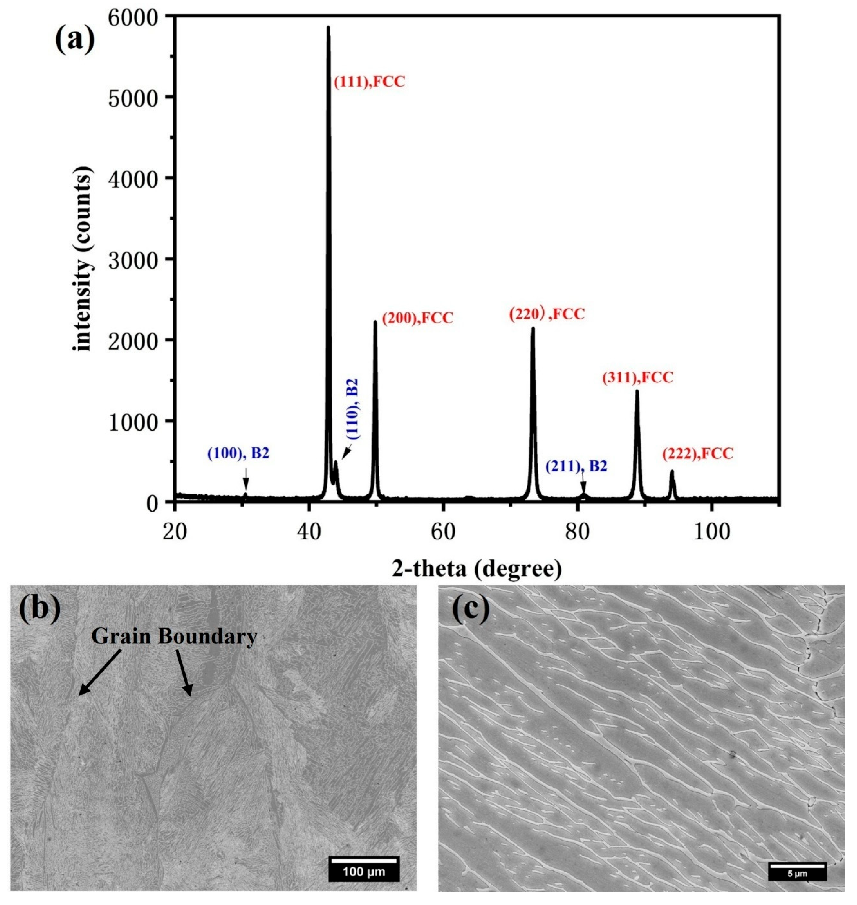
Figure 1. (a) XRD pattern of Fe36Ni18Mn33Al13 alloy, exhibiting that the alloys consist of FCC and B2 phases; SEM images of lamellar microstructures in the as-cast Fe36Ni18Mn33Al13 alloy at lower (b) and higher (c) magnifications. The dark phase is FCC, and the light phase is B2.
Crystals 15 00792 g001
Figure 2. (a) BF TEM image of the s-cast Fe36Ni18Mn33Al13 alloy with lamellar FCC and B2 phases; (b) CBED patterns from the B2 phase, with the {100} superlattice diffraction spots indicating its ordered BCC structure; (c) unit cell of a B2 lattice.
Crystals 15 00792 g002
Figure 3. (a) Two strain–stress curves of Fe36Ni18Mn33Al13 alloy tensile tested at a strain rate of 5 × 10⁻⁴ s−1; SEM images of Fe36Ni18Mn33Al13 tensile specimens after fracture at lower (b) and higher (c) magnifications, showing slip lines and cracks.
Crystals 15 00792 g003
Figure 4. Time-sequence BF TEM images of FCC phase captured during in situ straining showing the evolution of dislocation structures. Images recorded at (a) t0, (b) t0 + 3 s, (c) t1, and (d) t1 + 3 s illustrate: (i) dislocation propagation via planar slip and development of slip bands (indicated by dashed lines); (ii) generation of new dislocations (marked 0); and (iii) characteristic bowing due to pinning at ends (dislocation 2, 3 and 4). Extracted from Supplementary Material Movie 1.
Crystals 15 00792 g004
Figure 5. Time-sequence BF TEM images of FCC phase during in situ straining showing dislocation dynamics. Images captured at (a) t0, (b) t0 + 4 s, (c) t0 + 8 s, (d) t0 + 10 s, (e) t0 + 11 s, and (f) t0 + 12 s demonstrate: (i) migration and disappearance of dislocations 1, 2, and 3 (marked by red arrows); (ii) cross-slip events at obstacles (cross-slip plane indicated by red dashed line in c); and (iii) dislocation multiplication (dislocation marked 0; more details from Supplementary Material Movie 2).
Crystals 15 00792 g005
Figure 6. Time-sequence BF TEM images of FCC phase during in situ straining under increasing tensile load. Frames captured at: (a) t0, (b) t0 + 5 s, (c) t0 + 10 s, (d) t0 + 15 s, (e) t0 + 25s, (f) t0 + 30 s, (g) t0 + 40 s, and (h) t0 + 45 s show progressive development of: (i) dislocation glide and cross-slip events (dislocation cross-slip marked by red arrows in (a)); (ii) slip band formation and their intersection (marked by red dashed lines in (g)); and (iii) dislocation pile-up at phase boundaries (denoted in (h)). Extracted from Supplementary Materials Movie 3 and 4.
Crystals 15 00792 g006
Disclaimer/Publisher’s Note: The statements, opinions and data contained in all publications are solely those of the individual author(s) and contributor(s) and not of MDPI and/or the editor(s). MDPI and/or the editor(s) disclaim responsibility for any injury to people or property resulting from any ideas, methods, instructions or products referred to in the content.