Abstract
The elastic and photoelastic coefficients of Ba3TaGa3Si2O14 (BTGS) crystals were determined by the quantum–mechanical calculation technique. Based on these data, extreme piezo-optic surfaces π′°km were constructed, which describe the change in the path difference in light beams in the crystal under the influence of mechanical stress. The results for BTGS crystals are compared with the ones for other crystals of the langasite group (La3Ga5SiO14, Ca3Ga2Ge4O14, Ca3TaGa3Si2O14 and Ca3NbGa3Si2O14). The global maxima of the π′°km surfaces for BTGS crystals significantly exceed the ones for the other crystals mentioned above and, accordingly, BTGS crystals can be suitable for use in polarization-optic light modulators and devices based on them. The acousto-optic efficiency of BTGS crystals was evaluated. The correlations between the magnitude of the piezo- and elasto-optic coefficients and the parameters of the unit cell of the studied crystals were determined.
1. Introduction
Sensitive elements of optical modulating devices are, as a rule, bulk crystalline materials. The number of photoelastic materials that have been used in practice includes few crystals, so the task of finding new effective materials for controlling laser radiation is relevant.
Interest in crystals of the langasite group [1,2,3,4,5,6] is due to the fact that they reveal a unique combination of various physical properties. For instance, the temperature stability of physical characteristics, in particular elastic [7,8], as well as a large piezoelectric effect and a high coefficient of electromechanical coupling (e.g., the value of the piezoelectric coefficient d11 of langasite group crystals is in the range of 4…7 pC/N [9,10,11], that is 2…3 times higher than in quartz crystals [9])—makes them a popular material for development of acoustoelectronic devices [6]. In particular, they are used in pressure and detonation sensors, resonators in tunable generators, substrates of thermostable slices for acoustoelectronic filters on surface and bulk acoustic waves, Q-switches, as well as temperature-stable broadband monolithic filters used in mobile communication systems [12,13,14]. Because of a high optical damage threshold of ~1 GW/cm2 [15], these crystals can be used as sensitive elements in acousto-optical converters. The optical properties of crystals of the LGS group have also been widely studied, see, e.g., works [1,4,9,13,16,17]. However, the photoelastic properties of these crystals were not investigated until our first papers [18,19,20]. In our previous works, the piezo-, elasto- and acousto-optical properties of several representatives of this group were experimentally studied: crystals of langasite La3Ga5SiO14 (LGS) [18] and calcium halogermanate Ca3Ga2Ge4O14 (CGG) [20], which have a disordered structure (see [21]), and crystals of catangasite Ca3TaGa3Si2O14 (CTGS) [19] with an ordered structure (see [22]). However, for most crystals of the LGS group (for a list of these crystals, see, e.g., [21,22]), the piezo-optic effect (POE), the elasto-optic effect (ELOE), and the acousto-optic efficiency have not been studied. It is these effects that are interesting from the point of view of the application of crystals of the LGS group, because of the stability of physical characteristics, high optical quality of the crystals, their high mechanical strength [19,20], and transparency in the deep ultraviolet region (up to ~250 nm [1,9,20]).
Since it is problematic to experimentally study a large number of crystals by the laborious interferometric method [19,20,23], in paper [24] the photoelastic (piezo- and elasto-optic) coefficients of ordered CTGS and Ca3NbGa3Si2O14 (CNGS) crystals were calculated by the quantum–mechanical technique. The calculation results for CTGS crystals [24] agree well with the experimental data [19]. Therefore, in this paper, the elastic, piezo- and elasto-optic coefficients of ordered batangasite Ba3TaGa3Si2O14 (BTGS) crystals were calculated in a similar way. Based on these results, the spatial anisotropy of photoelasticity effects can be studied by the methods of indicative or extreme surfaces, see, e.g., [25,26,27,28]. Here the extreme surfaces describing the change in the path difference of the orthogonally polarized light beams
under the influence of mechanical stress σm is constructed and the maximum values of this effect are found (here Δnk is the birefringence of the crystal, dk is the thickness of the sample in the direction of light propagation). The results obtained for BTGS crystal are compared with similar ones for LGS, CTGS, CNGS and CGG.
δΔk = δ(Δnk·dk)
2. Material and Method for Determining Photoelastic Coefficients
BTGS crystals were chosen for calculating the piezo-optic coefficients (POCs) πim and elasto-optic coefficients (ELOCs) pik because their photoelastic properties have not been elucidated yet. In addition, because of the high refractive indices (ni ≈ 2 [29]), which are decisive for the value of the acousto-optic figure-of-merit M2, since M2 ~ [30,31,32], for these crystals, one can expect a higher AO efficiency than for other crystals of the LGS group, as well as a higher efficiency in terms of path difference, which can be used in polarization-optical light modulators and, accordingly, pressure sensors based on them [33,34,35,36].
In papers [24,37,38] quantum–mechanical calculation of POCs and ELOCs for a number of crystals using the CRYSTAL program [39] ensured good agreement with experimental data. Here, the calculation of photoelastic constants of BTGS crystals was also carried out using version CRYSTAL17 of this program [40]. The program implements automated algorithms for determination of elastic and piezoelectric [41], piezo-optic and elasto-optic [42] tensors for crystals of any symmetry. The hybrid PBE0 functional of the density functional theory (DFT) is used [43], which is known to provide accurate strain-related properties of solids [44,45,46]. The POB-TZVP-rev2 atom-centered Gaussian-type function basis set has been adopted for all elements [47,48]. The integration was performed on a 5 × 5 × 5 k-grid chosen by the Monkhrost-Pack method. Convergence of the self-consistent field step of the calculations is determined by a threshold on the energy set to 10−8 Hartree.
3. Results and Discussion
3.1. Elastic and Photoelastic Coefficients
BTGS crystals belong to the point group 32 [2] and, accordingly, have seven independent coefficients of elastic stiffness Cmk and elastic compliance Skm, as well as eight independent elasto-optic pik and piezo-optic πim coefficients [49,50]. The calculated values of elastic Cmk, Skm and photoelastic pik, πim coefficients for these crystals are indicated in Table 1 and Table 2.

Table 1.
Elastic coefficients Cmk (109 N/m2) and Skm (10−12 m2/N) of BTGS crystals calculated by quantum–mechanical technique (in comparison with literature data).
Table 2.
Piezo-optic πim (in units of 10−12 m2/N = Br = Brewster) and elasto-optic pik coefficients of BTGS crystals calculated by the quantum–mechanical technique.
As seen from Table 1, the agreement between the calculated (our data) and experimental [22,51] values of the elastic coefficients Cmk and Skm is mostly good. Further, these coefficients were used for calculation of the AO efficiency and constructing extreme surfaces of the change in the optical path difference δΔk between orthogonally polarized beams induced by the uniaxial pressure σm.
The highest value of POCs for BTGS crystals (Table 2) corresponds to the coefficient π33, as for other studied crystals of the LGS group [18,19,20]. For ELOCs, we see that the highest coefficients are p13 and p31, so the transverse effect prevails, as in CTGS [19] and CGG [20]. Let us pay attention to an interesting observation: if the values of the POE and ELOE in crystals of the LGS group are related to the crystal lattice parameters, then larger photoelastic effects are generally observed in CTGS [12,19], LGS [18] and BTGS crystals with a larger unit cell volume (V = 283.80 Å3 [52], 294.28 Å3 [53] and 326.03 Å3 [2], respectively) compared to the small value of V = 279.96 Å3 [54] for CGG crystals and, accordingly, the predominantly smaller values of POCs and ELOCs for this crystal [20]. It was also found that the maximum values of POE or ELOE are sensitive to the ratio of the cell parameters c/a. Namely, in the LGS crystal with a higher value of c/a = 0.6233 [55], longitudinal effects corresponding to the coefficients π33 and p33 [18] predominate, while in BTGS, CTGS and CGG crystals with smaller values of the c/a ratio (0.6097, 0.6148 and 0.6158, respectively [2,52,54]), transverse effects with the coefficients πi31, p13 and p31 [18,19,20] are more significant.
Note that crystals of the LGS group are often divided into ordered and disordered, see, e.g., papers [10,22,54,55]. If, according to the piezoelectric coefficients, there is a large difference between ordered crystals (e.g., CTGS, CNGS) and disordered ones (e.g., LGS, LGT) [10,11], then no clear patterns have been found for the photoelastic coefficients πim, pik. We can only note that for crystals with an ordered structure (CTGS, CNGS, BTGS) transverse elasto-optic effects prevail (i.e., the coefficients p13, p31 are larger), whereas for crystals with a disordered structure (LGS, CGG), similar patterns have not been revealed for either ELOE or POE.
3.2. Evaluation of Acousto-Optic Efficiency
Let us estimate the value of the AO figure-of-merit of BTGS crystal based on the known [30,31,32] expression
where ρ is the crystal density and Vk is the acoustic wave velocity.
For the conditions of AO interaction with a longitudinal acoustic wave, which correspond to the maximum ELOC p31 = 0.185 (Table 2), expression (2) should be substituted with this value of p31. At refractive index n3 = 1.8776 (for the wavelength of 632.8 nm [29]), the velocity of the longitudinal acoustic wave V3 = 5908 m/s, calculated by the Christoffel method [50] based on the elasticity coefficients Cmk (Table 1), and the density of BTGS crystal ρ = 5514 kg/m3 [2] were used. The result is M2 = 1.66·10−15 s3/kg. In terms of this M2 value, BTGS crystal is approximately two times superior to the strontium borate (SrB4O7) crystal, suitable for AO modulation of light in the ultraviolet range [56] and has a value comparable to the maximum of M2 of the CTGS crystal [19]. However, to find the maximum AO efficiency of BTGS crystal, it is necessary to construct AO figure-of-merit (M2) surfaces and analyze the anisotropy of these surfaces using the technique described, e.g., in [28].
3.3. Extreme Piezo-Optic Surfaces of the Path Difference
The path difference POE δΔk according to expression (1) consists of changing the birefringence Δnk and the sample thickness dk under the influence of mechanical stress σm. Such POE finds its application in polarization-optical light modulators, particularly, in pressure gauges based on them [33,34,35,36]. We call such surfaces extreme, because each point of the surface is obtained not simply as a result of calculation using a known expression, but as a consequence of optimization (searching for the maximum path difference in accordance with the direction of uniaxial pressure applying or light wave vector). This optimization is based on the well-known classical Levenberg–Marquardt algorithm [57]. To avoid the uncertainty caused by reaching a local maximum, the search was performed several times for each point of the surface, with 10 different initial values for each optimization parameter (i.e., the polar or azimuthal angle of the spherical coordinate system). It should also be noted that the calculations for each point of the surface were carried out independently, and reaching a local (non-global) maximum in such a case is usually reflected in the shape of the extreme surface and violates its symmetry caused by the symmetry of the crystal, or forms ‘dips’ on the surface. Such situations are easily traced; however, they were not encountered in the calculations of this work. The construction of extreme surfaces of the path difference is detailed, particularly, in [27].
Here the objective function of optimization is the absolute value of corresponding to the definition of POE by path difference [58]:
Based on this expression, we obtain the equation of the surface, which describes the change in the path difference for all directions of the applied uniaxial pressure and all light propagation directions , namely
where the dashes indicate the spatial distribution of all effects: is POE in terms of the path difference; and are POEs consisting refractive indices of orthogonally polarized waves and changes; is the birefringence; is the effective elastic compliance coefficient. It should be emphasized that all possible geometries of piezo-optic interaction were considered, and not only the conditions of orthogonality of and directions.
The calculation by the method of extreme surfaces (see, e.g., [27,28]) was carried out in two equivalent variants. In the first variant of the calculation, for each possible direction of light propagation, such a direction of uniaxial pressure σm was determined, which would provide the maximum of the path difference . The dependence of the obtained maximum values on the direction of the light wave can be represented in the form of a surface, which we call the wave vector extreme surface. The distances of the points of this surface from the origin of coordinates correspond to the absolute values of the maximum for each direction of the wave vector . Among all maxima obtained as a result of the calculation, the global maxima of this value were determined, which correspond to the maximum achievable POE of the path difference. In the second variant of the calculation, for each possible direction of uniaxial pressure, such a direction of wave vector was determined, which would also provide the maximum of surface. The corresponding extreme surface is called the surface of mechanical stress. Both types of surfaces have all the symmetry elements of the point group of the crystal and the center of inversion (i.e., they correspond to the Laue group of the crystal [59]). The symmetry reveals in the existence of few equivalent global maxima. Although the wave vector and mechanical stress surfaces differ in form, the maximum achievable global maxima of the POE must be the same for both of them.
Parameters of LGS, CGG, CTGS, CNGS and BTGS crystals (πim, Skm, ni) used for construction of extreme surfaces were taken from [18,19,20,24,29] and Table 1 and Table 2.
The examples of the extreme surfaces of the POE by the path difference, constructed in accordance with (4), are shown in Figure 1 and Figure 2. The results of the optimization for the experimentally studied (by interferometric method) crystals CGG [20], CTGS [19] and LGS [18] and the theoretically studied (by quantum–mechanical method) crystals CTGS [24], CNGS [24] and BTGS (this paper) are indicated in Table 3 and Table 4. These tables provide data on the position of one of the global maxima, the positions of other ones can be determined using the symmetry elements of the point group 32 supplemented by inversion in accordance with the symmetry of the expressions used for calculations (specifically, the use of the absolute value of as the objective function).
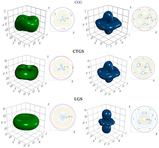
Figure 1.
The extreme surfaces of the wave vector (left) and mechanical stress (right) for CGG, CTGS and LGS crystals; the inserts show the stereographic projections of the surfaces. The optimization is based on the experimental data; all values are in Br (10−12 m2/N).
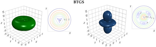
Figure 2.
The extreme surfaces of the wave vector (left) and mechanical stress (right) for BTGS crystal; the inserts show the stereographic projections of the surfaces. The optimization is based on the data obtained by quantum–mechanical method; all values are in Br.
Table 3.
Maximal values and angle parameters for the extreme surfaces of POE in CGG, CTGS and LGS crystals; the optimization is based on the experimental data.
Table 4.
Maximal values and angle parameters for the extreme surfaces of POE in CTGS, CNGS and BTGS crystals; the optimization is based on the data obtained by quantum–mechanical method.
As seen from Table 3, for CGG and CTGS crystals, the maximum values of the surfaces were obtained for the case of orthogonal conditions of piezo-optic interaction (α = 90°), when the direction of pressure applying coincides with the main crystallographic axis X, and light propagates in the main crystallographic plane YZ in directions determined by the angles θk = 104° and 101.3° to the optical axis Z of the considered crystals. For LGS crystal, the most effective geometry of piezo-optic interaction corresponds to the case when the light propagates and the uniaxial pressure is applied in the crystallographic plane YZ. The optimal geometry of interaction is not strictly orthogonal, the angle α is equal to 95.5°. The smallest global value of POE by the path difference is obtained for CGG crystal (Table 3). This result is obviously caused by the values of the refractive indices ni, birefringence Δnk and piezo-optic coefficients πim of this crystal, which are lower compared to other representatives of the langasite group [20].
It should be emphasized that Figure 1 and Figure 2 give a qualitative representation of the anisotropy of the POE in terms of the path difference, whereas Table 3 and Table 4 present quantitative results of the maximum (global) values of the piezo-optic extreme surfaces of the path difference.
- (1)
- The directions of light propagation indicated in these tables do not correspond to the main crystallographic axes (an exception exists only for BTGS crystal, see rows 4 and 5 in Table 4); the directions of light propagation and uniaxial pressure applying are either strictly orthogonal (α = 90°, see rows 1 and 2 in Table 3 and rows 1 and 5 in Table 4), or deviate from orthogonality by small angles from 2.4° to 5.5° (see row 3 in Table 3 and rows 2–4 in Table 4);
- (2)
- Among the experimentally and theoretically studied crystals, the maximal value of was obtained for BTGS crystal (14.5 Br);
- (3)
- CGG crystal reveals the lowest global maximum of (6.8 Br); for comparison, the maximum value of the POE (in terms of path difference) for quartz found by the extreme surface method is equal to 7.4 Br, which is also significantly (by a factor of 2) lower than that for BTGS crystal (Table 4). Therefore, it is BTGS crystals that should be preferred when using them as sensitive elements of polarization-optic light modulators and devices based on them.
4. Conclusions
All elastic and photoelastic (piezo-optic and elasto-optic) coefficients of BTGS crystals were calculated using the quantum–mechanical method realized in the CRYSTAL17 program. Based on the calculated elastic compliance coefficients Skm and piezo-optic coefficients πim, as well as the known values of the refractive indices ni for the light wavelength λ = 632.8 nm, extreme surfaces of the POE were constructed, which describe the spatial distribution of the change in the path difference δΔk caused by the influence of the mechanical stress σm. The maximum (global) values of the piezo-optic extreme surfaces of the path difference were found by the Levenberg–Marquardt method. The results obtained for BTGS crystals are compared with the ones for other crystals of the langasite group: LGS, CGG, CTGS and CNGS. The main result of the research is that the BTGS crystal reveals the highest value of the POE among all studied crystals of langasite group (14.5 Br). This value is significantly (twice) higher than the one for quartz (7.4 Br). Therefore, BTGS crystals should be preferred when used as sensitive elements of polarization-optic light modulators and devices based on them.
The value of the AO figure-of-merit M2 of BTGS crystal was estimated based on the highest elasto-optic coefficient p31. According to the obtained value of M2 = 1.66·10−15 s3/kg, BTGS crystal is twice as much as the strontium borate crystal (SrB4O7), which is suitable for acousto-optic modulation of light in the ultraviolet range.
It should be emphasized that for the studied crystals, a correlation was found between the value of the piezo-optic πim and elasto-optic pik coefficients on the one hand and the volume of the crystal lattice on the other. Moreover, the values of the πim and pik coefficients correlate with the value of the ratio of the unit cell parameters c/a.
It was also found that for crystals with an ordered structure (CTGS, CNGS, BTGS), the transverse elasto-optic effects (corresponding to the coefficients p13, p31) prevail, and for crystals with a disordered structure (LGS, CGG), similar regularities were not determined for either ELOE or POE.
Based on the results obtained, it can be stated that by changing the parameters of the unit cell by incorporating the appropriate cations in the crystal structure, the photoelastic properties of crystals of the langasite group can be controlled. For example, replacing the Ca2+ cation with Ba2+ in crystals with an ordered structure (CTGS, BTGS) leads to a significant increase in the maximum POE value by the path difference (by about 50%), namely, from 10.4 Br for CTGS to 14.5 Br for BTGS.
It is clear that before developing recommendations for the practical use of an effective (based on quantum–mechanical calculation) photoelastic material, a thorough experimental verification (by interferometry methods) of the calculated values of POCs and ELOCs should be carried out. In other words, the method of quantum–mechanical calculation should be considered as an effective express technique for the initial assessment of the photoelastic characteristics of considered crystals.
Author Contributions
Conceptualization, B.M.; methodology, N.D. and O.B.; software, O.B. and P.S.; validation, B.M.; formal analysis, A.A.; investigation, N.D., B.M., O.B., P.S. and O.L.; writing—original draft preparation, N.D.; writing—review and editing, B.M.; visualization, P.S.; supervision, B.M. and A.A.; project administration, B.M. and A.A. All authors have read and agreed to the published version of the manuscript.
Funding
This research has received funding from the Ministry of Education and Science of Ukraine in the frames of ‘Nanoelectronics’ (0123U101695). We acknowledge the support of the European Union under Horizon Europe for the TeraHertz project (Grant Agreement 101086493).
Data Availability Statement
All data generated or analyzed during this study are included in this published article.
Conflicts of Interest
The authors declare no conflicts of interest.
References
- Remark, T.; Segonds, P.; Debray, J.; Jegouso, D.; Víllora, E.; Shimamura, K.; Boulanger, B. Linear and nonlinear optical properties of the langasite crystal Ca3TaAl3Si2O14. Opt. Mater. Expr. 2023, 13, 2053–2060. [Google Scholar] [CrossRef]
- Usui, H.; Kusakabe, H.; Tokuda, M.; Sugiyama, K.; Hoshina, T.; Tsurumi, T.; Takeda, H. Structure and electrical properties of Ba3TaGa3Si2O14 single crystals grown by Czochralski method. J. Ceram. Soc. Jpn. 2020, 128, 441–446. [Google Scholar] [CrossRef]
- Kuzmin, N.; Klimin, S.; Mavrin, B.; Boldyrev, K.; Chernyshev, V.; Mill, B.; Popova, M. Lattice dynamics and structure of the new langasites Ln3CrGe3Be2O14 (Ln = La, Pr, Nd): Vibration alspectra and abinitio calculations. J. Phys. Chem. Solids 2020, 138, 109266. [Google Scholar] [CrossRef]
- Golovina, T.; Konstantinova, A.; Zabelina, E.; Kozlova, N.; Kasimova, V. Allowance for the imperfection of the spectrophotometric complex optical elements when measuring transmission spectra of gyrotropic uniaxial crystals. I: Samples are cut perpendicular to the optical axis. Cryst. Rep. 2025, 70, 39–49. [Google Scholar] [CrossRef]
- Deng, M.; Chen, J.; Zhang, J.; Xie, W.; Jin, H.; Xuan, W.; Dong, S.; Luo, J. Numerical design and optimization of high performance Langasite and hetero-acoustic layer-based surface acoustic wave device. Micromachines 2025, 16, 166. [Google Scholar] [CrossRef]
- Roshchupkin, D.; Kovalev, D. Coefficients of thermal expansion in La3Ga5SiO14 and Ca3TaGa3Si2O14 crystals. Materials 2023, 16, 4470. [Google Scholar] [CrossRef]
- Andreev, I. Two decades following the discovery of thermallys table elastic properties of La3Ga5SiO14 crystal and coining of the term langasite. Tech. Phys. 2004, 49, 1101–1103. [Google Scholar] [CrossRef]
- Andreev, I.; Dubovik, M. A new piezoelectric material, langasite (La3Ga5SiO14), with a zero temperature coefficient of the elastic vibration frecuency. Sov. Tech. Phys. Lett. 1984, 10, 205–207. [Google Scholar]
- Fu, X.; Villora, E.; Matsushita, Y.; Kitanaka, Y.; Noguchi, Y.; Miyayama, M.; Shimamura, K.; Ohashi, N. Influence of growth conditions on the optical, electrical resistivity and piezoelectric properties of Ca3TaGa3Si2O14 single crystals. J. Ceram. Soc. Jpn. 2016, 124, 523–527. [Google Scholar] [CrossRef]
- Irzhak, D.; Roshchupkin, D. Piezoelectric strain coefficients in La3Ga5.3Ta0.5Al0.2O14 and Ca3TaGa3Si2O14 crystals. AIP Adv. 2013, 3, 102108. [Google Scholar] [CrossRef]
- Irzhak, D.; Roshchupkin, D. Measurement of independent piezoelectric moduli of Ca3NbGa3Si2O14, La3Ga5.5Ta0.5O14 and La3Ga5SiO14 single crystals. J. Appl. Cryst. 2018, 51, 1174–1181. [Google Scholar] [CrossRef]
- Fritze, H. High-temperature bulk acoustic wave sensors. Meas. Sci. Technol. 2011, 22, 012002. [Google Scholar] [CrossRef]
- Xin, Y.; Shaojun, Z.; Jiyang, W. Mutualaction of the opticalactivity and the electro-optic effect and itsinf luence on the La3Ga5SiO14 crystal electro-optic Q switch. J. Opt. Soc. Am. B 2005, 22, 394–397. [Google Scholar] [CrossRef]
- Zhang, J.; Tan, Q.; Zhang, L.; Zhao, N.; Liang, X. Langasite bonding via high temperature for fabricating sealed microcavity of pressure sensors. Micromachines 2022, 13, 479. [Google Scholar] [CrossRef] [PubMed]
- Kong, H.; Wang, J.; Zhang, H.; Yin, X.; Zhang, S.; Liu, Y.; Cheng, X.; Gao, L.; Hu, X.; Jiang, M. Growth, properties and application as an electrooptic Q-switch of langasite crystal. J. Cryst. Growth 2003, 254, 360–367. [Google Scholar] [CrossRef]
- Boursier, E.; Segonds, P.; Boulanger, B.; Félix, C.; Debray, J.; Jegouso, D.; Ménaert, B.; Roshchupkin, D.; Shoji, I. Phase-matching directions, refined sellmeier equations, and second-order nonlinear coefficient of the infrared langatate crystal La3Ga5.5Ta0.5O14. Opt. Lett. 2014, 39, 4033–4036. [Google Scholar] [CrossRef]
- Boursier, E.; Giedre, M.; Delagnes, J.-C.; Petit, S.; Ernotte, G.; Lassonde, P.; Segonds, P.; Boulanger, B.; Petit, Y.; Légaré, F.; et al. Study of middle infrared difference frequency generation using a femtosecond laser source in LGT. Opt. Lett. 2017, 42, 3698–3701. [Google Scholar] [CrossRef]
- Mytsyk, B.; Demyanyshyn, N.; Andrushchak, A.; Kost’, Y.; Parasyuk, O.; Kityk, A. Piezooptical coefficients of La3Ga5SiO14 and CaWO4 crystals: A combined optical interferometry and polarization-optical study. Opt. Mater. 2010, 33, 26–30. [Google Scholar] [CrossRef]
- Mytsyk, B.; Suhak, Y.; Demyanyshyn, N.; Buryy, O.; Syvorotka, N.; Sugak, D.; Ubizskii, S.; Fritze, H. Full set of piezo-optic and elasto-optic coefficients of Ca3TaGa3Si2O14 crystals at room temperature. Appl. Opt. 2020, 59, 8951–8958. [Google Scholar] [CrossRef]
- Mytsyk, B.; Demyanyshyn, N.; Andrushchak, A.; Maksishko, Y.; Kohut, Z.; Kityk, A. Characterization of photoelastic materials by Mach-Zehnder interferometry: Application to trigonal calcium galogermanate (CGG) crystals. J. Appl. Phys. 2024, 135, 085111. [Google Scholar] [CrossRef]
- Chani, V.; Shimamura, K.; Yu, Y.; Fukuda, T. Design of newoxidecrystals with improved structural stability. J. Mater. Sci. Eng. 1997, 20, 281–338. [Google Scholar] [CrossRef]
- Zheng, Y.; Cui, S.; Chen, J.; Tu, X.; Xin, J.; Kong, H.; Shi, E. Advances in design, growth and application of piezoelectric crystals with langasite structure. Proc. 2012 Symposium on Piezoelectricity, Acoustic Waves, and Device Applications (SPAWDA), Shanghai, China, 23–25 November 2012; IEEE Xplore: Piscataway, NJ, USA, 2013; pp. 252–259. [Google Scholar]
- Mytsyk, B.; Kryvyy, T.; Demyanyshyn, N.; Mys, O.; Martynyuk-Lototska, I.; Kokhan, O.; Vlokh, R. Piezo-, elasto- and acousto-optic properties of Tl3AsS4 crystals. Appl. Opt. 2018, 57, 3796–3801. [Google Scholar] [CrossRef]
- Mytsyk, B.; Erba, A.; Maul, J.; Demyanyshyn, N.; Shchepanskyi, P.; Syrotynsky, O. Photoelasticity of CNGS crystals. Appl. Opt. 2023, 62, 7952–7959. [Google Scholar] [CrossRef]
- Mytsyk, B.; Demyanyshyn, N. Piezooptic surfaces of lithium niobate crystals. Crystallogr. Rep. 2006, 51, 653–660. [Google Scholar] [CrossRef]
- Mytsyk, B.; Andrushchak, A. Spatial distribution of the longitudinal and transverse piezooptical effect in lithium tantalate crystals. Crystallogr. Rep. 1996, 41, 1001–1006. [Google Scholar]
- Buryy, O.; Demyanyshyn, N.; Mytsyk, B.; Andrushchak, A. Optimization of the piezooptic interaction geometry in SrB4O7 crystal. Opt. Applik. 2016, XLVI, 447–459. [Google Scholar]
- Buryy, O.; Demyanyshyn, N.; Mytsyk, B.; Andrushchak, A.; Sugak, D. Acousto-optic interaction in LGS and CTGS crystals. Opt. Contin. 2022, 1, 1314–1323. [Google Scholar] [CrossRef]
- Konstantinova, A.; Golovina, T.; Nabatov, B.; Dudka, A.; Mill, B. Experimental and theoretical determination of the optical rotation in langasite family crystals. Crystallogr. Rep. 2015, 60, 907–914. [Google Scholar] [CrossRef]
- Pinnow, D.; Van, G.; Warner, A.; Bonner, W. Lead molybdate: A melt-grown crystal with a high figure of merit for acousto-optic device applications. Appl. Phys. Lett. 1969, 15, 83–86. [Google Scholar] [CrossRef]
- Dixon, R. Photoelastic properties of selected materials and their relevance for applications to acoustic light modulators and scanners. J. Appl. Phys. 1967, 38, 5149–5153. [Google Scholar] [CrossRef]
- Uchida, N.; Niizeki, N. Acoustooptic deflection materials and techniques. Proc. IEEE 1973, 61, 1073–1092. [Google Scholar] [CrossRef]
- Spillman, W.B., Jr. Multimode fiber-optic pressure sensor based on the photoelastic effect. Opt. Lett. 1982, 7, 388–390. [Google Scholar] [CrossRef]
- Trainer, N. Photoelastic Measuring Transducer and Accelerometer Based Thereon. U.S. Patent 4,648,273, 10 March 1987. [Google Scholar]
- Andrushchak, A.; Mytsyk, B.; Osyka, B. Polarized-optical pressure meter. Devices Tech. Exp. 1990, 3, 241. (In Russian) [Google Scholar]
- Wang, B. Linear birefringence measurement instrument using two photoelastic modulators. Opt. Eng. 2000, 41, 981–987. [Google Scholar] [CrossRef]
- Erba, A.; Ruggiero, M.; Korter, T.; Dovesi, R. Piezo-optic tensor of crystals from quantum-mechanical calculations. J. Chem. Phys. 2015, 143, 144504. [Google Scholar] [CrossRef]
- Demyanyshyn, N.; Mytsyk, B.; Andrushchak, A.; Kityk, A. Photoelasticity of crystals with the scheelite structure: Quantum mechanical calculations. Acta Crystallogr. Sect. B 2025, B81, 47–54. [Google Scholar] [CrossRef] [PubMed]
- Perger, W.; Criswell, J.; Civalleri, B.; Dovesi, R. Ab-initio calculation of elastic constants of crystalline systems with the CRYSTAL code. Comput. Phys. Commun. 2009, 180, 1753–1759. [Google Scholar] [CrossRef]
- Dovesi, R.; Erba, A.; Orlando, R.; Zicovich-Wilson, C.; Civalleri, B.; Maschio, L.; Rèrat, M.; Casassa, S.; Baima, J.; Salustro, S.; et al. Quantum-mechanical condensed matter simulations with CRYSTAL. WIREs Comput. Mol. Sci. 2018, 8, e1360. [Google Scholar] [CrossRef]
- Erba, A.; Caglioti, D.; Zicovich-Wilson, C.; Dovesi, R. Nuclear-relaxed elastic and piezoelectric constants of aterials: Computational aspects of two quantum-mechanical approaches. J. Comput. Chem. 2017, 38, 257–264. [Google Scholar] [CrossRef]
- Erba, A.; Dovesi, R. Photoelasticity of crystals from theoretical simulations. Phys. Rev. 2013, B88, 045121. [Google Scholar] [CrossRef]
- Adamo, C.; Barone, V. Toward reliable density functional methods without adjustable parameters: The PBE0 model. J. Chem. Phys. 1999, 110, 6158–6170. [Google Scholar] [CrossRef]
- Mahmoud, A.; Erba, A.; El-Kelany, K.; Rérat, M.; Orlando, R. Low-temperature phase of BaTiO3: Piezoelectric, dielectric, elastic and photoelastic properties from ab initio simulations. Phys. Rev. 2014, B89, 045103. [Google Scholar] [CrossRef]
- El-Kelany, K.; Carbonnière, P.; Erba, A.; Rérat, M. Inducing a finite in-plane piezoelectricity in graphene with low concentration of inversion symmetry-breaking defects. J. Phys. Chem. C 2015, 119, 8966–8973. [Google Scholar] [CrossRef]
- El-Kelany, K.; Carbonnière, P.; Erba, A.; Sotiropoulos, J.-M.; Rérat, M. Piezoelectricity of functionalized graphene: A quantum mechanical rationalization. J. Phys. Chem. C 2016, 120, 7795–7803. [Google Scholar] [CrossRef]
- Laun, J.; Bredow, T. BSSE-corrected consistent Gaussian basis sets of triple-zeta valence with polarization quality of the sixth period for solid-state calculations. J. Comput. Chem. 2021, 42, 1064–1072. [Google Scholar] [CrossRef] [PubMed]
- Laun, J.; Bredow, T. BSSE-corrected consistent Gaussian basis sets of triple-zeta valence with polarization quality of the fifth period for solid-state calculations. J. Comput. Chem. 2022, 43, 839–846. [Google Scholar] [CrossRef]
- Nye, J.F. Physical Properties of Crystals; Oxford: Clarendon Press: Oxford, UK, 1964. [Google Scholar]
- Narasimhamurty, T. Photoelastic and Electro-Optic Properties of Crystals; Plenum Press: New York, NY, USA; London, UK, 1981. [Google Scholar]
- Dudka, A. Ab Initio calculation of elastic and electromechanical constants of langasite family crystals. Crystallogr. Rep. 2012, 57, 131–133. [Google Scholar] [CrossRef]
- Wang, Z.; Yu, W.; Yuan, D.; Wang, X.; Xue, G.; Shi, X.; Xu, D.; Lv, M. Crystal structure of tricacium tantalum trigallium disilicon oxide, Ca3TaGa3Si2O14. Z. Für Krist.—New Cryst. Struct. 2003, 218, 389–390. [Google Scholar]
- Dudka, A. New multicell model for describing the atomic structure of La3Ga5SiO14 piezoelectric crystal: Unitcells of different compositions in the same single crystal. Crystallogr. Rep. 2017, 62, 195–204. [Google Scholar] [CrossRef]
- Dudka, A.; Mill, B. Accurate crystal-structure refinement of Ca3Ga2Ge4O14 at 295 and 100 K and analysis of the disorder in the atomic positions. Crystallogr. Rep. 2013, 58, 594–603. [Google Scholar] [CrossRef]
- Chait, B.; Bustamante, A.; Chout, M. A new class of ordered langasite structure compound. In Proceedings of the 2000 IEEE/EIA International Frequency Control Symposium and Exhibition (Cat. No.00CH37052), New York, NY, USA, 9 June 2000; pp. 163–168. [Google Scholar]
- Mytsyk, B.; Demyanyshyn, N.; Martynyuk-Lototska, I.; Vlokh, R. Piezo-optic, photoelastic, and acousto-optic properties of SrB4O7 crystals. Appl. Opt. 2011, 50, 3889–3895. [Google Scholar] [CrossRef] [PubMed]
- Press, W.; Teukolsky, S.; Vetterling, W.; Flannery, B. Numerical Recipes in C. The Art of Scientific Computing, 2nd ed.; Cambridge University Press: Cambridge, UK, 1992. [Google Scholar]
- Mytsyk, B. Methods for the studies of the piezo-optical effect in crystals and the analysis of experimental data. I. Methodology for the studies of piezo-optical effect. Ukr. J. Phys. Opt. 2003, 4, 1–26. [Google Scholar] [CrossRef] [PubMed]
- Sirotin, Y.; Shaskolskaja, M. Fundamentals of Crystal Physics; Mir Publishers: Moscow, Russia, 1982. [Google Scholar]
Disclaimer/Publisher’s Note: The statements, opinions and data contained in all publications are solely those of the individual author(s) and contributor(s) and not of MDPI and/or the editor(s). MDPI and/or the editor(s) disclaim responsibility for any injury to people or property resulting from any ideas, methods, instructions or products referred to in the content. |
© 2025 by the authors. Licensee MDPI, Basel, Switzerland. This article is an open access article distributed under the terms and conditions of the Creative Commons Attribution (CC BY) license (https://creativecommons.org/licenses/by/4.0/).