Article

Influence of Energetic Xe132 Ion Irradiation on Optical, Luminescent and Structural Properties of Ce-Doped Y3Al5O12 Single Crystals

by
Ruslan A. Assylbayev
1,
Gulnur Tursumbayeva
2,
Guldar Baubekova
2,*,
Zhakyp T. Karipbayev
2,*,
Aleksei Krasnikov
3,
Evgeni Shablonin
3,
Gulnara M. Aralbayeva
2,
Yevheniia Smortsova
4,
Abdirash Akilbekov
2,
Anatoli I. Popov
2,5 and
Aleksandr Lushchik
3
1
Department of Mathematics and Physics, Margulan University, Toraigyrov Str. 58, Pavlodar 140000, Kazakhstan
2
Institute of Physical and Technical Sciences, L.N. Gumilyov Eurasian National University, Munaitpasov Str. 13, Astana 010008, Kazakhstan
3
Institute of Physics, University of Tartu, W. Ostwald Str. 1, 50411 Tartu, Estonia
4
Deutsches Elektronen-Synchrotron (DESY), 22603 Hamburg, Germany
5
Institute of Solid State Physics, University of Latvia, Kengaraga 8, LV-1063 Riga, Latvia
*
Authors to whom correspondence should be addressed.
Crystals 2025, 15(8), 683; https://doi.org/10.3390/cryst15080683 (registering DOI)
Submission received: 4 July 2025 / Revised: 25 July 2025 / Accepted: 26 July 2025 / Published: 27 July 2025
(This article belongs to the Special Issue Research Progress of Photoluminescent Materials)

Abstract

The impact of 230-MeV Xe132 ion irradiation on the structural, optical, and luminescent properties of YAG:Ce single crystals is investigated over a fluence range of 1011–1014 ions/cm2. Optical absorption; cathodo-, X-ray, and photoluminescence; and X-ray diffraction are employed to analyze radiation-induced changes. Irradiation leads to the formation of Frenkel (F, F+) and antisite defects and attenuates Ce3+ emission (via enhanced nonradiative processes and Ce3+ → Ce4+ recharging). A redistribution between the fast and slow components of the Ce3+-emission is considered. Excitation spectra show the suppression of exciton-related emission bands, as well as a shift of the excitation onset due to increased lattice disorder. XRD data confirm partial amorphization and a high level of local lattice disordering, both increasing with irradiation fluence. These findings provide insight into radiation-induced processes in YAG:Ce, which are relevant for its application in radiation–hard scintillation detectors.

1. Introduction

Yttrium aluminum garnet single crystals doped with trivalent cerium ions, Y3Al5O12:Ce (YAG:Ce), have unique optical and luminescent properties, including high emission efficiency, excellent thermal and radiation stability, and a broad emission spectrum in the visible range. They are used in a wide range of advanced technological applications [1,2,3,4,5,6,7,8,9,10].
YAG:Ce has been widely employed as a scintillation material in medical diagnostics and radiation monitoring systems. The scintillation properties of YAG:Ce crystals have been extensively studied (see, for example, [11,12,13,14]). These crystals exhibit fast timing characteristics, emit around 2.25 eV (550 nm), and demonstrate good compatibility with silicon photodetectors, enabling efficient energy conversion and the possibility of particle identification based on the shape of the light signal. Owing to these features, the YAG:Ce can be used for the detection of γ-radiation and light charged particles with high temporal and energy resolution [15,16,17,18,19].
The thermal stability and radiation tolerance of YAG:Ce make it a promising material for the use under extreme conditions, such as those encountered in outer space and high-energy physics environments [20,21,22,23]. However, under intense radiation, stable lattice defects may form within the crystal, including oxygen vacancies, antisite defects, and their complexes. These defects can significantly affect the optical and luminescent properties of the material. Therefore, the investigation of radiation-induced changes in the structure and properties of YAG:Ce is a critical step toward the development of components suitable for operation in harsh environment conditions.
Ion irradiation is widely employed as an accelerated method for radiation damage accumulation in the materials used in the active zones of nuclear reactors [24,25]. Unlike neutron irradiation, it allows for high radiation doses to be reached within short timeframes, avoiding sample activation [25]. Many studies have examined radiation-induced processes in undoped YAG single crystals under exposure to high-energy ions and fast fission neutrons [26,27,28,29,30]. However, there is a notable lack of research focused on ion irradiation effects in YAG:Ce, a material of considerable technological importance. In the present work, we report experimental results on the effects of 230-MeV Xe132 ion irradiation on the optical, luminescent, and structural properties of YAG:Ce single crystals.
The irradiation of YAG:Ce crystals with 230-MeV Xe132 ions is characterized by highly asymmetric energy deposition between ionizing and non-ionizing channels. According to SRIM calculations [31], the electronic stopping power (Se) reaches 25.3 keV/nm, while the nuclear stopping power (Sn) is only 0.08 keV/nm, resulting in a Se/Sn ratio exceeding 300. This indicates that over 99.7% of the ion’s energy loss is transferred via the formation of electronic excitations, whereas less than 0.3% contributes to the elastic collisions of incident particles with material nuclei (the creation of interstitial vacancy Frenkel defect pairs). In this context, Xe132 ion irradiation cannot be directly equated to γ or neutron irradiation. While γ-rays deposit energy almost exclusively via ionization (with uniform distribution), and neutrons act via nuclear collisions (pure impact mechanism), swift heavy ions such as Xe132 combine extremely high ionizing effects in nanometric volumes with a modest impact contribution. Therefore, Xe132 ion irradiation emulates a unique radiation environment that simultaneously models high-dose ionization and displacement damage, making it particularly suitable for the accelerated testing of radiation-resistant scintillators.

2. Materials and Methods

In this study, Y3Al5O12:Ce3+ single crystals with a 0.5 at.% Ce3+ dopant concentration, grown by the Czochralski method, were investigated. Samples with dimensions of 5 × 5 × 0.5 mm3 were supplied by Alineason Materials Technology GmbH (Frankfurt, Germany). Y3Al5O12:Ce3+ crystals were irradiated with 230-MeV xenon (Xe132) ions at a fluence of Φ = 1011–1014 ions/cm2 using the DC-60 cyclotron (Astana, Kazakhstan). The penetration depth (range R) of these Xe ions, according to SRIM/TRIM calculations [31], is about 14.3 μm. The beam current density was 10 nA/cm2. The total irradiation dose was estimated to be 5.6 × 10⁵ Gy for the lowest fluence of Φ = 1011 ions/cm2 and 5.6 × 10⁸ Gy for the highest fluence of Φ = 1014 ions/cm2.
Optical absorption spectra were measured using a Jasco 660 dual-beam spectrophotometer (Japan Spectroscopic Company, Tokyo, Japan). The absorption of a pristine crystal was subtracted from the spectrum for the same sample after irradiation and this difference spectrum was considered the radiation-induced optical absorption (RIOA).
Time-resolved spectra of cathodoluminescence (CL) were measured at 1.5–6.1 eV under the excitation by 100-keV electron pulses of sub-nanosecond duration (for setup details, see Ref. [32]). The luminescence signal was registered in two time-windows, delayed after the excitation pulse: within 0–32 ns or 0–2 ms. The CL spectra were corrected for the spectral response of the detection system.
X-ray luminescence (XL) spectra of irradiated YAG:Ce single crystals were measured under identical conditions (25 kV, 10 mA, room temperature (RT)) using a Horiba iHR320 monochromator (HORIBA Scientific, Grabels, France).
Time-resolved photoluminescence (PL) was measured using an MDR206 monochromator (Lomo Photonica, Saint Petersburg, Russia) coupled with a Tektronix TDS 2205 digital oscilloscope (Tektronix, Inc., Portland, OR, USA). The detection system included a Hamamatsu H6780-04 photomultiplier tube (Hamamatsu, Japan), which ensured high sensitivity and fast response for time-resolved measurements. Excitation was provided by a tunable Solar LQ215 laser system (Minsk, Belarus) with LP603 and LG350 modules, delivering 10-ns pulses in the 210–2500 nm spectral range.
Vacuum ultraviolet (VUV) excited luminescence measurements were performed at the Superlumi/P66 beamline at DESY’s PETRA III synchrotron facility (Hamburg, Germany); for details, see previous studies [33,34]. The synchrotron radiation provided high-intensity, tunable excitation, with precise wavelength selection via a 2 m monochromator offering 4 Å spectral resolution. This setup enabled the targeted excitation of luminescent states in the ceramics, particularly in the VUV region.
Emission spectra were recorded with a 0.3 m Kymera 328i (Oxford Instruments, UK) monochromator (F/4.1 aperture, 200–1200 nm range, 0.4 nm resolution). A Newton 920 CCD camera (Oxford Instruments, Oxfordshire, UK) ensured high sensitivity across a wide spectral range, and a Hamamatsu R6358 photomultiplier tube (Hamamatsu, Japan) was used for efficient photon counting in the UV. All experiments were carried out at 9 K using a helium-cooled cryostat to reduce thermal noise and non-radiative losses. Excitation spectra were calibrated against the sodium salicylate signal to ensure reliable data across the entire spectral range.
The X-ray diffraction (XRD) measurements were performed on crystalline samples of YAG:Ce, with both pristine reference samples and those subjected to ion irradiation, using a Bruker D6 Eco (Bruker) diffractometer (Bruker, Berlin, Germany). We followed the protocol established in previous studies [33]. All measurements were carried out under identical conditions to ensure the reliability and comparability of the results. The instrument was operated in a wide angular range to provide comprehensive phase identification and the accurate quantitative analysis of structural parameters. Each sample was mounted so that XRD data were collected specifically from the irradiated surfaces of the crystals. The diffractometer was equipped with a Cu Kα radiation source (λ = 1.5406 Å) and operated at 40 kV and 40 mA. Data collection was performed in the range from 10° to 90°, with a step size of 0.02° and a counting time of 1 s per step, ensuring precise determination of the diffraction peak positions and widths. This approach guarantees high reproducibility and accuracy in the phase analysis and structural refinement, making it suitable for detailed investigations of microstructural parameters such as the crystallite size, microstrain, and degree of crystallinity.
The degree of crystallinity of a material is determined based on the XRD pattern as the ratio of the area occupied by the crystalline peaks to the total area, including both the crystalline and amorphous components. To estimate the microstrain, the broadening of diffraction peaks is analyzed using the Williamson–Hall formalism (see Refs. [35,36] for details. Thus, both parameters—the degree of crystallinity and the microstrain—are directly extracted from the quantitative analysis of the X-ray diffraction profile.

3. Results and Discussion

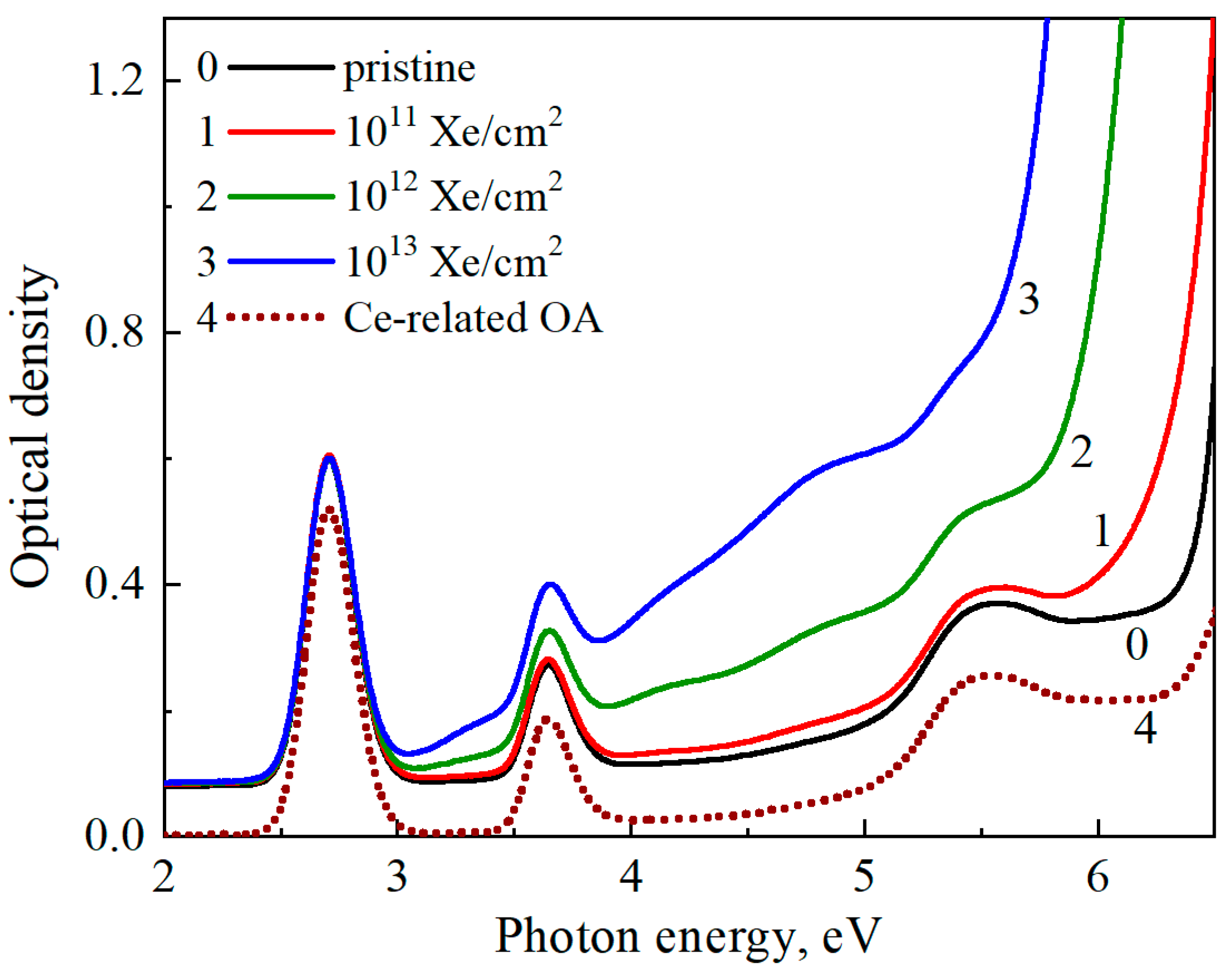
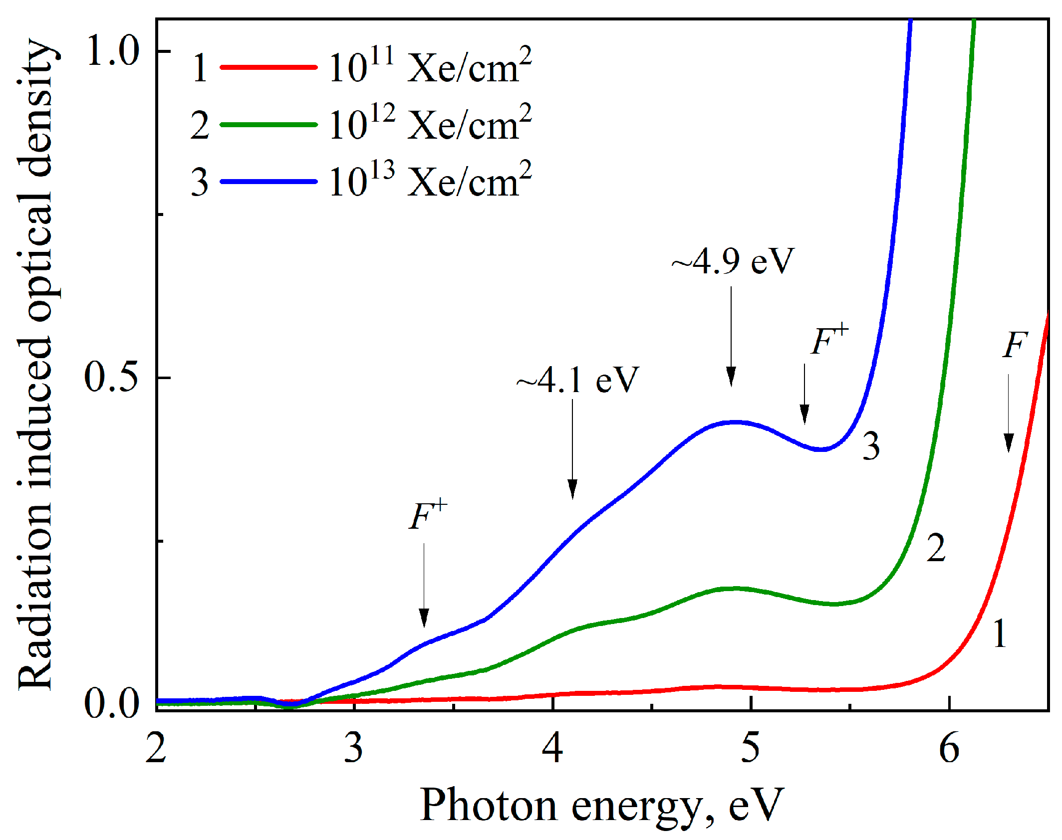
3.1. Optical Absorption of Xe-Irradiated YAG:Ce Single Crystals

Figure 1 presents the optical absorption spectra measured at RT for YAG:Ce single crystals exposed to Xe132 ions with different fluences (curves 1–3). Curve 4 presents the difference spectrum between optical absorption of two pristine YAG crystals with the same thickness: a Ce-doped (curve 0) one and a nominally pure one. This difference spectrum clearly reflects Ce-related optical absorption. Ce3+ ions substitute for host Y3+ cations at crystallographic sites exhibiting D2 symmetry, which leads to the crystal field splitting of the 5d excited state into five sublevels. The absorption features centered at approximately 5.46 eV, 3.65 eV, and 2.7 eV are thus ascribed to 4f1 → 5d1 transitions of Ce3+ ions [37,38].
Figure 2 displays the spectra of the radiation-induced optical absorption of Xe-irradiated YAG:Ce crystals (the absorption of a pristine YAG:Ce crystal is subtracted from the spectra shown in Figure 1). The RIOA spectra exhibit a pronounced increase in absorption around 3.35, 4.1, 4.9 eV and above 6 eV. At least a part of the RIOA is related to classical F and F+ centers (an oxygen vacancy with two or one trapped electrons, respectively). The arrows in Figure 2 note the position of band maxima tentatively ascribed to the oxygen-vacancy-related defects in thermochemically reduced (additively colored) and nominally pure YAG single crystals [39,40].
Some publications (see, e.g., [30,41]) considering the characteristics of oxygen-vacancy-related defects refer to the data for additively colored YAG crystals [26,27]. Similar to other metal oxides, the F center possesses one absorption band peaked around 6.35 eV, while up to three bands could be related to the F+ center; according to the existing literature data, two F+-related bands are tentatively located in YAG around 3.35 and 5.3 eV.
There are speculations about the existence of an oxygen vacancy with three trapped electrons, with the absorption bands peaked at 1.49, 2.58, and 3.44 eV belonging to this F center in thermochemically reduced YAG crystals [39]. However, according to Ref. [42], the centers responsible for absorption bands at 1.5, 2.5, and 3.5 eV in UV-irradiated YAG crystals already undergo thermal destruction at 175 K. Furthermore, the probability of the F center formation (if any) should be inherently lower than that for the formation of F+ and F centers, which involve one and two electrons, respectively.
Note that the second absorption band attributed to the F+ centers (maximum around 5.3 eV) lies on the short-wavelength side of an intense 4.9-eV band and cannot be clearly separated in ion-irradiated crystals (see Figure 2). In earlier studies [43,44], the 4.9 eV band was ascribed to charge-transfer transitions involving the 2p orbital of oxygen ligands and the 3d level of Fe3+ impurity ions. Recently, the absorption bands at 4.1 and 4.9 eV in Xe-irradiated YAG have been tentatively attributed to the F+ center associated with a Fe2+ impurity or YAl3+ antisite defect, respectively [45]. In our opinion, the latter suggestion is still questionable (especially with respect to the F+-Fe2+ centers).
In general, the concentration of radiation-induced F-type defects significantly exceeds the concentration of uncontrolled impurities and even antisite defects in single crystals. Therefore, the concentration of single (not associated with any imperfection in its nearest vicinity) radiation-induced F+ centers should be significantly higher than that for the above-mentioned associations. However, according to Figure 2, the intensity of the F+-band around 3.35 eV is low with respect to the bands at 4.1 and 4.9 eV.
At the same time, it should be stressed that radiation-induced defects are formed only within a thin layer of a YAG crystal, the width of which is determined by the penetration depth R of incident energetic ions. As a result, the absolute number of radiation defects is rather small and the separation of different defect types is complicated. In addition, the tentative F-absorption band is located at 6.35 eV, i.e., spectrally very close to the beginning of intrinsic absorption; first, this is due to exciton-like formations and is then followed by band-to-band transitions (see, e.g., similar processes in ion-irradiated LuAG crystals [33,46]). Unfortunately, we did not succeed in separating the F-band, although the rise in RIOA in the relevant spectral region of YAG with ion fluence is obvious (see Figure 2). The detail study of thermal annealing of the F centers (via optical absorption) in irradiated or additively colored YAG crystals is definitely needed and still lies ahead.
It is worth noting that, in contrast to radiation-induced defects in a thin colored crystal layer, the existing impurity ions are distributed in the whole crystal volume, enhancing impurity-related absorption bands. The used ion irradiation is characterized by very efficient ionization losses (extremely high density of electronic excitations along ion tracks; see [46] and references therein). Thus, the formed electron–hole pairs can cause impurity recharging within rather thick layers (with thickness significantly exceeding the R value) of the irradiated crystal. In particular, iron ions are invariably present in nominally pure YAG crystals; they also contribute to the increase in optical absorption following radiation exposure [47]. Fe3+ ions substitute for Al3+ in both octahedral and tetrahedral coordination sites. The absence of Fe3+-related absorption bands in the spectrum of pristine YAG:Ce suggests that iron impurities initially exist in the divalent Fe2+ state. Indeed, in as-grown YAG crystals, iron is predominantly present as Fe2+ [43]. Irradiation of YAG by Xe132 ions leads to the formation of Fe3+ impurities, which could be also responsible for the RIOA bands around 4.1 and 4.9 eV (see Figure 2).

3.2. Cathodoluminescence Spectra of Xe-Irradiated YAG Crystals

Figure 3 shows the CL spectra of ion-irradiated YAG crystals (Φ = 1013 Xe/cm2) measured at 6 K (a) or RT (b) using two different time-windows: 0–32 ns and 0–2 ms.
The suggested F+ center emission band in YAG should peak around 3.1 eV [40,41]. Similar to the case of thoroughly studied MgO and Al2O3 single crystals (see, e.g., [48,49]), the F+ emission is very fast, with the decay time τ in the nanosecond scale (according to [40], τ = 3 ns in YAG). However, there is no evident F+-related emission even in CL spectra measured at 6 K and within a short time-window (0–32 ns, see Figure 3a). At the same time, several CL bands at 3.6–5.5 eV are detectable at low temperatures. A comparison of CL intensity measured in short and a long time-windows (0–2 ms) confirms that the emissions are rather slow (significantly weaker in a short window of 0–32 ns). Based on literature data (see, e.g., [50,51,52,53,54] and references therein), UV emissions are related to exciton-like states, including bound excitons near antisite defects.
It should be mentioned that a strong attenuation of CL in a wide spectral region under energetic ion irradiation was reported for a number of wide-gap metal oxides. In particular, the F+ centers of emission at 3.8 eV (τ around 2 ns) in corundum increase with Xe-irradiation only at very low fluences and already significantly attenuate at Φ > 1012 Xe/cm2 [55]. The irradiation-induced attenuation of intrinsic emissions (connected with self-trapped or bound excitons) takes place in all metal oxides, while the rate of intensity decrease with ion fluence could be different. According to Figure 3a,b, intrinsic emissions in Xe-irradiated YAG are clearly detectable at both 6 K and RT. At the same time, there is an evident redistribution with registration temperature between the emissions connected with different exciton-like formations (see also [50,54,56]). At low temperatures, the dominant contribution to UV luminescence arises from self-trapped excitons (CL peak around 4.9 eV), while different excitons bound near antisite defects are responsible for the CL bands shifted toward lower energies at RT (Figure 3b).

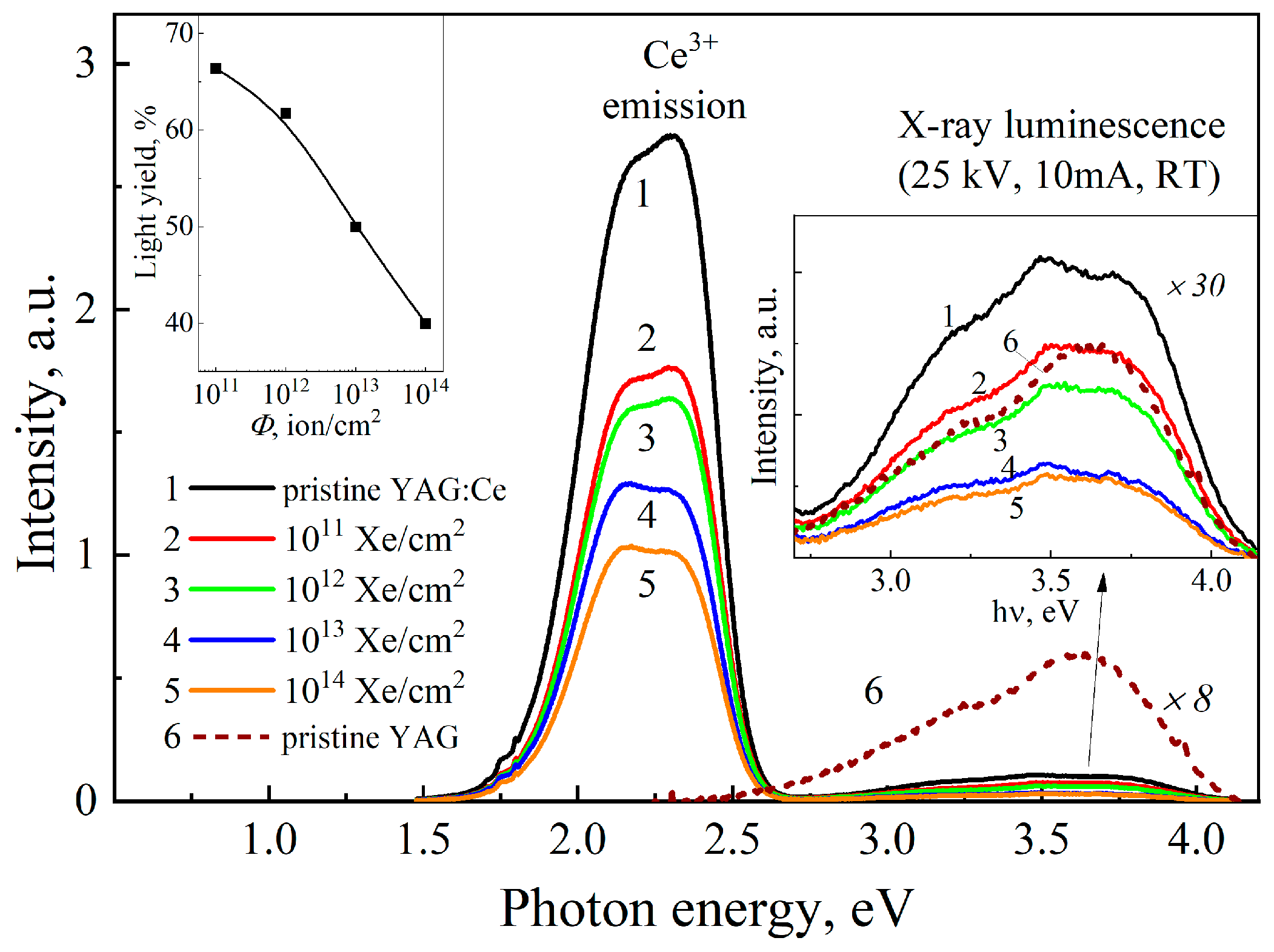
3.3. X-Ray Luminescence Spectra of Xe-Irradiated YAG:Ce Crystals

In YAG:Ce crystals, the primary luminescent center in the visible spectral range is the Ce3+ ion. Its characteristic emission manifests as a broad, asymmetric band with a maximum near 2.25 eV. The luminescence properties of Ce3+ in the YAG host matrix have been extensively studied [51,52,57].
Figure 4 presents the X-ray luminescence spectra of YAG:Ce single crystals irradiated with Xe132 ions to various fluences. All XL spectra were recorded under identical experimental conditions to ensure the reliable comparison of lightsum variations. The Ce-emission lightsum (integral) of the pristine YAG:Ce crystal was taken as a reference value and arbitrarily set to 100%.
In the pristine sample, the characteristic Ce3+ emission band is observed in the 1.8–2.5 eV range. This band exhibits a doublet structure and originates from 5d → 4f transitions. Upon increasing the irradiation dose, a progressive decrease in the intensity of this complex emission band is recorded. The overall reduction in luminescence intensity is evidently attributed to the formation of radiation-induced defects, which act as nonradiative recombination centers, disrupt energy transfer to the Ce3+ centers and, thereby, diminish luminescence efficiency.
Moreover, ion irradiation leads to an intensity redistribution between two sub-bands of the Ce3+ emission. This redistribution is likely due to the distortion of the local environment and symmetry breaking of the crystal field, which alters the radiative transition probabilities from different 5d sublevels. Thus, the observed changes in the XL band provide clear evidence of the significant impact of radiation-induced defects on the electronic and optical properties of YAG:Ce and underscore the material’s sensitivity to intense radiation.
The inset in Figure 4 presents the fluence dependence of the lightsum (LS) of XL at 1.8–2.5 eV in the irradiated YAG:Ce crystals. There is a clear exponential decrease in LS with irradiation dose and dropping at the highest fluence of Φ = 1014 ions/cm2 to about 40% of the LS value in a pristine sample. This behavior results from the combined influence of several physical mechanisms. Primarily, the interaction of high-energy ions with the crystal lattice leads to the formation of radiation-induced defects, such as interstitial-vacancy Frenkel pairs, antisite defects, and their complexes. These defects could act as efficient nonradiative recombination centers and impede the energy transfer to Ce3+ ions.
Ion irradiation of YAG:Ce also causes a redistribution of the charge states of cerium ions, whereby a fraction of Ce3+ is converted to Ce4+. The majority of the energy deposited by the incident ion is expended through ionization losses. As a result, Ce3+ impurities located along the ion tracks may lose their 4f electrons. The radiation-induced defects (in particular, oxygen vacancies) could stabilize the Ce4+ state, which is optically inactive. This Ce3+ → Ce4+ recharging process reduces the number of luminescent centers and, thus, contributes to the decline in LS.
In addition to Ce3+ emissions, the XL spectra also exhibit a significantly weaker complex band in the blue–UV region (2.8–4.3 eV, see inset in Figure 4). The LS of this XL band is about 7% with respect to the Ce3+ emission in a pristine YAG:Ce. In general, this weak band can be caused by the presence of a small concentration of radiation-induced F-type defects, single ones or associated with antisite defects. The latter are present in any as-grown YAG and are additionally created by the intense irradiation (see, e.g., [45,53,54]). Similar to other wide-gap metal oxides, the radiation defects in YAG are formed due to the displacement mechanism, while the contribution of ionization losses to Frenkel defect creation is negligible [46,55]. It is worth noting that, according to the EPR studies [58], even a single YAl3+ antisite defect can significantly alter the spectroscopic characteristics of a neighbor Ce3+ ion.
The detailed interpretation of XL origin at 2.8–4.3 eV is complicated due to its weakness and the influence of reabsorption by the existing impurity centers and defects (see also the discussion related to CL data presented in the Section 2). Similar to the case of Ce-related XL at 1.8–2.5 eV, the intensity of the blue–UV complex band decreases with ion fluence (suppression is mainly caused by the efficient nonradiative processes).

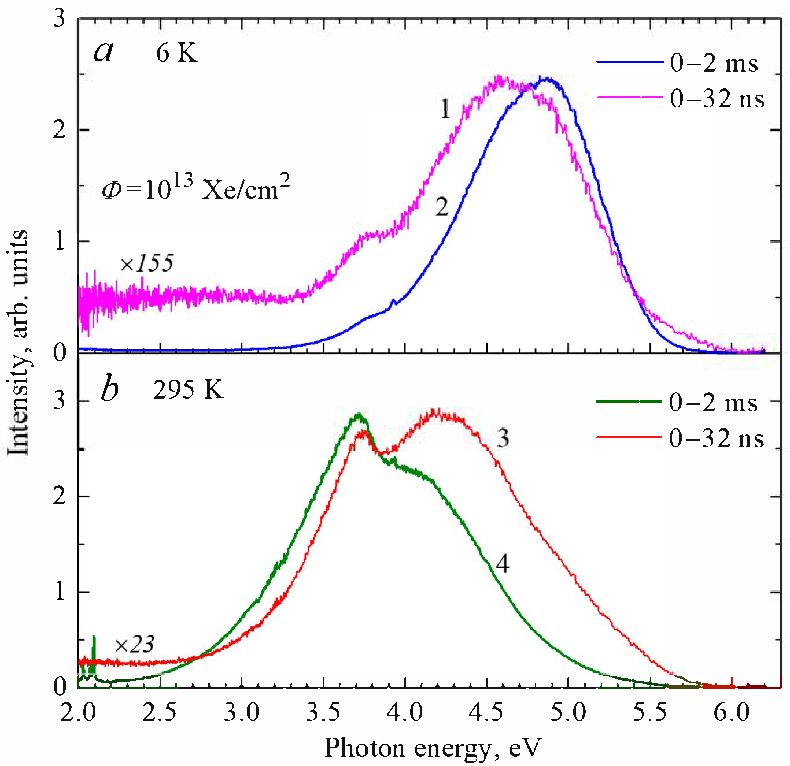
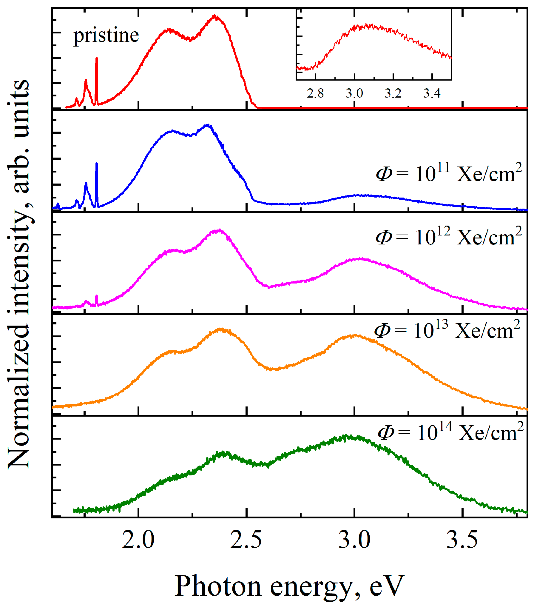
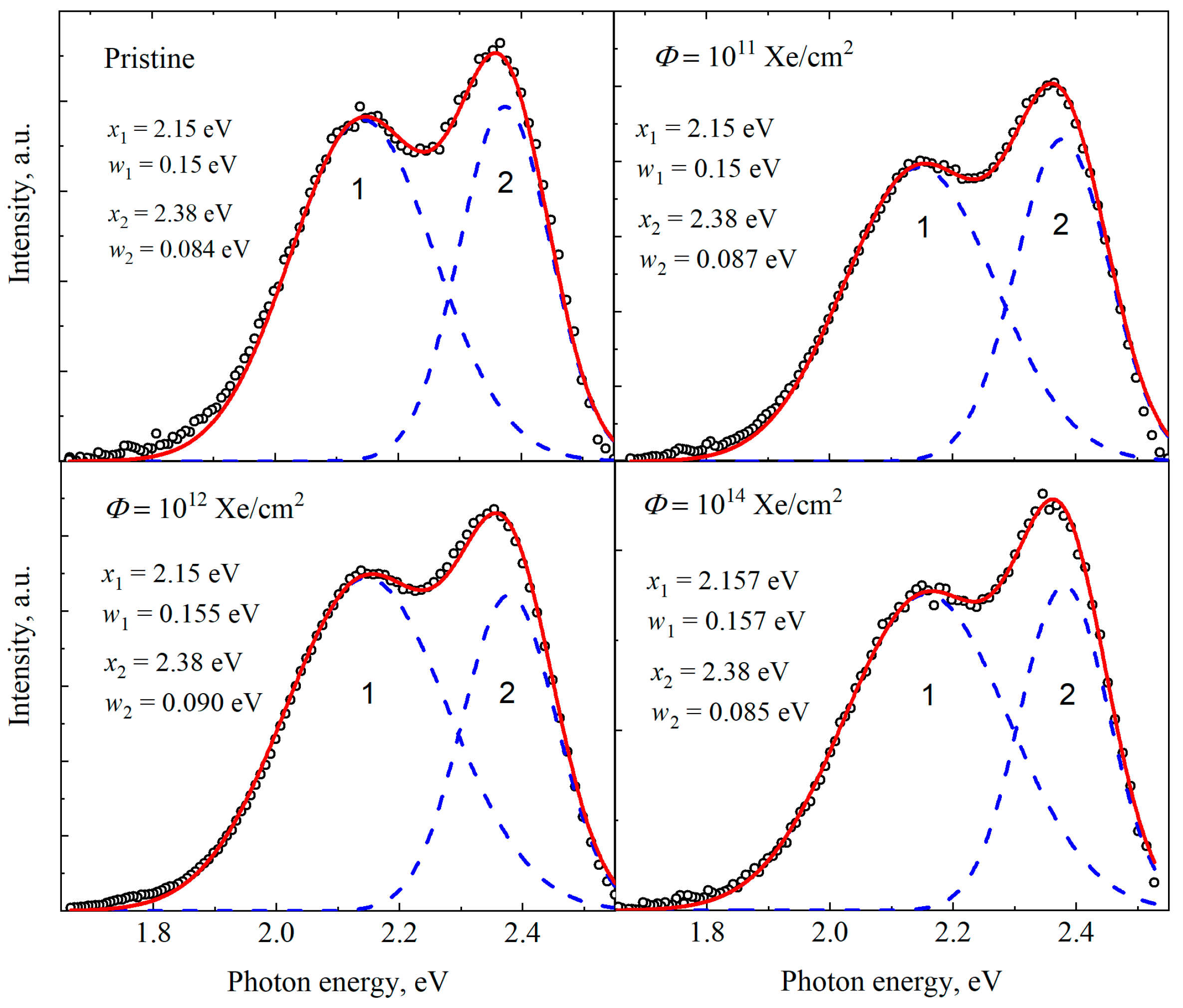
3.4. Photoluminescence Studies

Figure 5 shows the emission spectra measured in a spectral range of 1.5–4 eV for pristine and Xe-irradiated YAG:Ce crystals under the excitation by 6.2-eV photons at 10 K. The spectra consist of an intense Ce3+ emission in the visible region (~1.9–2.5 eV) and weaker emissions in the blue–UV region (~2.6–3.5 eV). The Ce3+ emission exhibits a noticeable doublet structure with peaks at 2.14 and 2.35 eV, corresponding to the 5d → 4f transitions. A broad complex band around 3 eV is evidently associated with radiation-induced defects.
In a pristine YAG:Ce sample, the intracenter emission of Ce3+ ions is clearly dominant. In irradiated crystals, there is a clear relative enhancement (with respect to a cerium intracenter luminescence) of short-wavelength defect-related emissions with ion fluence. According to the literature data, photons of 6.2 eV should excite the emission of the F and F+ centers [39,40] and could tentatively create exciton-like formations bound to antisite defects (see, e.g., [59] and references therein). However, mentioned in Section 3.2 and Section 3.3, the separation of elementary luminescence bands related to single F and F+ centers, or their associations with antisite defects, is complicated due to the rather small number of ion-induced Frenkel defects, additional reabsorption by defects/impurities, and efficient radiation-induced nonradiative processes. In particular, Figure 5 demonstrates significant attenuation of the Ce-luminescence in the sample irradiated with Φ = 1014 Xe/cm2.
Figure 6 presents spectra of the Ce3+ emission measured at the excitation of ion-irradiated YAG:Ce crystals by 5.54-eV photons at 10 K. The spectra are decomposed into two elementary Gaussians, the parameters of which (FWHM—w and maximum position—x) exhibit no significant changes in pristine and irradiated samples. This indicates that Xe-ion-irradiation does not significantly affect the shape of the Ce3+ emission bands.
Figure 7 presents the excitation spectra for the Ce3+ emission at 2.14 and 2.35 eV (Figure 7a,b), as well as for the short-wavelength emission band that peaks near 3.1 eV (Figure 7c), for YAG:Ce samples irradiated to different fluences. Two Ce3+-emission bands exhibit identical excitation spectra. The excitation band at 5.5 eV corresponds to one of the absorption bands of Ce3+ ions in the YAG matrix (see Figure 1) and is associated with 4f1 → 5d1 intracenter transitions. A low-energy excitation tail extending below 4 eV corresponds to another similar Ce-related absorption band (which cannot be reached via available synchrotron radiation). A weak excitation feature near 6 eV is visible in a pristine sample and gradually disappears with irradiation fluence.
An intense excitation band around 6.7 eV in the pristine sample is related to a bound exciton near a Ce3+ ion [54,60,61,62]. With irradiation fluence, this excitation band undergoes shape distortion, gradually diminishes in intensity and, after Φ = 1014 Xe/cm2, is almost completely suppressed. Such attenuation of the 6.7-eV excitation band with fluence is most likely due to the formation of Frenkel defects, the enhancement of lattice local disordering, and suppression of the exciton-related energy transfer mechanisms.
According to Figure 7, Ce3+ luminescence is also excited in the 7–9 eV spectral region, which corresponds to the formation of excitons in regular lattice regions as well as electron–hole pairs via interband transitions starting around 8 eV (see [54] and references therein). It is worth noting that the excitation bands in this spectral region are attenuated even after low Φ and are practically suppressed by Φ = 1013 Xe/cm2.
The luminescence band peaked around 3 eV in YAG and YAG:Ce crystals is commonly attributed either to the F, F+ centers [39,63] or their associations with antisite defects [46]. However, as noted above, a low number of single (isolated) F+ centers are created under Xe132 ion irradiation in a very thin crystal layer. Moreover, there is no excitation band around 5.3 eV in Figure 7c, which is considered as the second absorption band of the F+ centers in thermochemically reduced YAG crystals. In a pristine YAG:Ce crystal, the 3.1-eV emission is excited only via the interband transitions. At the same time, the excitation bands at 5.8–6.5 eV for the 3.1-eV emission in the irradiated YAG:Ce crystals could testify to the creation of the F centers by energetic Xe ions (their characteristic absorption band should be located near the edge of fundamental absorption [39,40]). Secondly, the observed redshift of a pronounced excitation band with irradiation fluence (Figure 7c) could be also associated with the absorption Urbach tail transformation due to the accumulation of radiation damage. However, the Urbach tail is usually nicely pronounced at RT, while the relevant changes at 10 K could tentatively be smaller than those in Figure 7c. Finally, if the radiation-induced F-center concentration corresponds to rather high absorption constant values, the excitation band of tentative F-emission could be seriously distorted (after a certain limit, the emission intensity is no longer proportional to the relevant defect concentration).

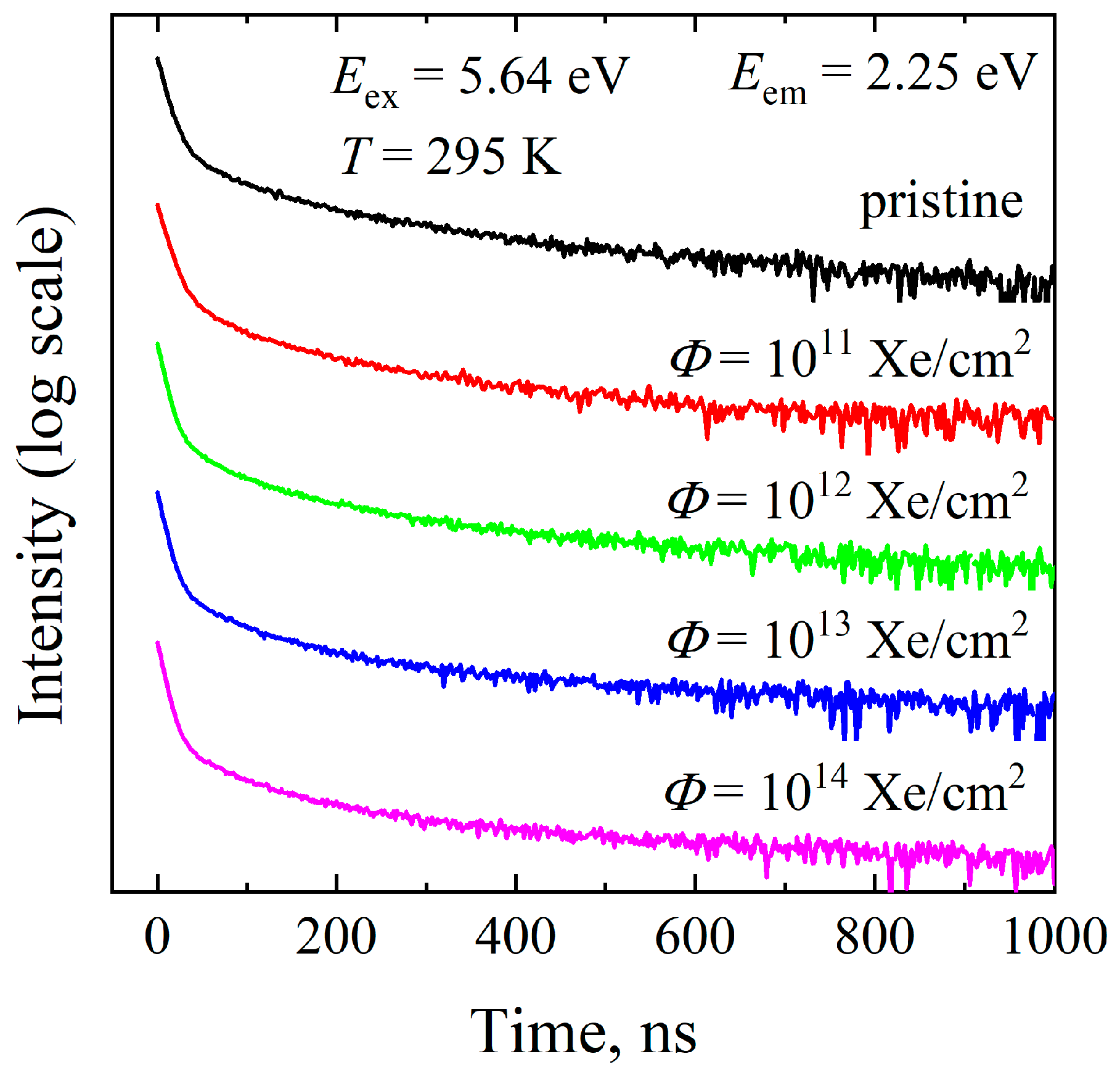
3.5. Photoluminescence Decay Kinetics

The influence of ion-irradiation on the decay kinetics of cerium emission was also studied. The decay kinetics of the 2.25 eV emission of Ce3+ impurity ions was measured under the excitation by 5.64-eV laser light at RT. Figure 8 displays the decay curves of the Ce emission in YAG:Ce crystals exposed to different fluences of Xe ions. In all cases, the kinetics are well described by two exponential components. The first, fast component exhibits τ1 = 70 ns in a pristine crystal and is slightly slower in the irradiated crystals, with τ1 = 75 ns. The decay time for the second, slow component equals τ2 = 320 ns in a pristine YAG:Ce and increases with ion fluence up to τ2 = 620 ns for Φ = 1014 Xe/cm2 (see Figure 9 and Table 1).
The lifetime of the fast component agrees well with previous studies (see, e.g., [54]). This component corresponds to the intracenter excitation of the Ce3+ ions, while the slow component is usually attributed to the energy transfer from a matrix (or other imperfections) to Ce3+ luminescent centers. Ion irradiation has only a minor effect on the lifetime of the Ce3+ intracenter emission, and small τ1 changes could be associated with a local distortion of the luminescence center vicinity. In contrast, the τ2 is clearly affected by the accumulated radiation-induced damage. In YAG single crystals, antisite defects, the concentration of which increases with ion fluence, can also participate in the processes of energy transfer to luminescent centers. As a result, the contribution of the slow cerium emission component increases with fluence, in turn causing the degradation of the scintillation performance.
Table 1 and the inset in Figure 9 illustrate the changes in the relative lightsum Si/S of both components of the Ce3+ emission with ion-irradiation fluence. For each component, the lightsum was estimated as the product S i = A i × τ i , where A i —is the preexponential factor. The total light sum was calculated as S = i S i .
The fast component lightsum S1 decreases significantly with irradiation fluence. The main reason for this reduction could be connected to the radiation-induced recharging of cerium ions, Ce3+ → Ce4+. In contrast, the lightsum of a slow component S2 increases with the irradiation dose. Such enhancement is connected with the increasing contribution of radiation-induced antisite defects to the processes of energy transfer toward Ce3+ luminescence centers.

3.6. X-Ray Diffraction

Irradiation with 230-MeV xenon ions induces structural modifications in the crystal lattice of YAG:Ce, leading to a rearrangement of its parameters depending on the accumulated radiation damage. Phase identification in the investigated samples was performed using data from the ICDD 2019+ database, in particular, PDF 04–026-6921, which contains reference crystallographic parameters for Y2.985Ce0.015Al5O12. Comparison of the obtained diffraction patterns with this reference enabled the characterization of structural changes, as well as the identification of newly formed irradiation-induced phases and defects. Figure 10a,b and Table 2 show the X-ray diffraction patterns of YAG:Ce crystals irradiated with different fluences up to 1014 ions/cm2.
It is well known that YAG is susceptible to amorphization under high-energy ion irradiation [28,64,65,66]. Amorphization of the YAG:Ce crystal structure under 230-MeV xenon ion irradiation manifests through a series of characteristic structural changes revealed by X-ray diffraction analysis. One of the key indicators is a reduction in crystallinity: while the pristine sample exhibits complete crystalline order (100°%), this value decreases to about 70% with increasing fluence, indicating partial lattice disordering and the formation of amorphous regions along ion tracks within the thin irradiated crystal layer. In the diffraction patterns, this is accompanied by background broadening and a reduction in the intensity of crystalline peaks within the range 2θ = 23.5–46.5° (Figure 10b), where no amorphous scattering was initially present. At a fluence of 1011 Xe/cm2, the onset of amorphous contributions becomes noticeable; at Φ = 1012 Xe/cm2, broad amorphous bands appear, which become increasingly pronounced at Φ = 1013 and especially Φ = 1014 Xe/cm2. It has recently been shown that the irradiation of Gd3Ga5O12 by 147-MeV Kr ions causes the formation of an amorphous halo in the region of 2θ = 31–35° [67]. This characteristic halo indicates the emergence of the regions with disordering of the crystal structure as a result of radiation damage and the breaking of chemical bonds. An increase in the irradiation fluence leads to a corresponding rise in the intensity of the halo, indicating a greater contribution of disordered regions within the structure.
These results indicate progressive degradation of crystalline order, associated with the accumulation of radiation-induced defects and atomic rearrangements within the lattice. Thus, the irradiation process leads to partial amorphization of the YAG:Ce structure, accompanied by reduced density, increased microstrain, and a higher dislocation density—collectively reflecting the breakdown and destabilization of the original crystalline phase.
Despite the presence of partial amorphization (with crystallinity reduced by 30%), the concentration of optically active color centers (F and F+ centers) induced by ion irradiation remains relatively low.

4. Conclusions

The present study studies the influence of ion-irradiation (230-MeV Xe132 ions) on the structural, optical, and luminescent properties of YAG:Ce single crystals over a wide range of fluences (1011–1014 ions/cm2). A comprehensive set of experimental techniques were used, including optical absorption spectroscopy; cathodo-, X-ray, and photoluminescence; luminescence decay kinetics; and X-ray diffraction.
The manifestations of the creation of point lattice defects (the F and F+ center, YAl3+ antisite defects), as well as the recharging of impurity ions (in particular, Ce3+ → Ce4+), were considered on the basis of optical absorption/cathodoluminescence spectra of YAG crystals exposed to energetic Xe ions with different fluences. Due to the relatively low absolute number of Frenkel defects induced by ion-irradiation, a further detail analysis of their characteristics is needed.
X-ray luminescence measurements demonstrated a continuous attenuation of Ce3+ emission with ion-irradiation fluence due to the enhancement of nonradiative processes (in particular, the creation of lattice defects) and the possible recharging of Ce3+ to optically inactive Ce4+. The emission band of Ce3+ preserved its spectral shape and substructure, indicating that the crystal field environment remains largely intact for residual Ce3+ centers. On the other hand, the fast component of intracenter Ce3+ emission (τ1 = 70–75 ns) decreases in intensity with irradiation fluence, while the slow component (determined by the energy transfer processes) behaves in the opposite way. Photoluminescence studies demonstrate the similar attenuation of Ce-related emission/excitation bands with irradiation fluence of YAG:Ce crystals.
The XRD analysis confirmed the partial amorphization of the YAG:Ce lattice at high fluences, with crystallinity decreasing to ~70%. The broadening and reduction of diffraction peaks indicate a high level of local lattice disordering consistent with ion track formation and defect accumulation.

Author Contributions

Conceptualization, Z.T.K., A.I.P. and A.L.; methodology, Z.T.K., A.A., A.I.P. and A.L.; validation, G.M.A.; formal analysis, A.K. and A.I.P.; investigation, G.M.A. and Y.S.; resources, G.B. and Y.S.; data curation, G.T., G.B., Z.T.K., A.K., E.S. and Y.S.; writing—original draft preparation, R.A.A., G.T. and Z.T.K.; writing—review and editing, R.A.A., G.T., G.B. and A.L.; visualization, R.A.A. and E.S.; supervision, A.A.; project administration, G.B.; funding acquisition, G.B. All authors have read and agreed to the published version of the manuscript.

Funding

This research was funded by the Science Committee of the Ministry of Science and Higher Education of the Republic of Kazakhstan (Grant No. AP19574768) and partially supported by the Estonian Research Council grant (PRG 2031). A.I.P also thanks the Latvian research project lzp-2023/1–0453 “Prediction of long-term stability of functional materials under extreme radiation conditions”.

Data Availability Statement

The raw data supporting the conclusions of this article will be made available by the authors on request.

Conflicts of Interest

The authors declare no conflicts of interests.

References

  1. Buryi, M.; Gaston-Bellegarde, A.M.; Pejchal, J.; Levchenko, F.; Remeš, Z.; Ridzoňová, K.; Babin, V.; Chertopalov, S. The role of Er3+ content in the luminescence properties of Y3Al5O12 single crystals: Incorporation into the lattice and defect state creation. Crystals 2023, 13, 562. [Google Scholar] [CrossRef]
  2. Buryi, M.; Havlák, L.; Jarý, V.; Bárta, J.; Laguta, V.; Beitlerová, A.; Li, J.; Chen, X.; Yuan, Y.; Liu, Q.; et al. Specific absorption in Y3Al5O12:Eu ceramics and the role of stable Eu2+ in energy transfer processes. J. Mater. Chem. C Mater. 2020, 8, 8823–8839. [Google Scholar] [CrossRef]
  3. Vistorskaja, D.; Katelnikovas, A.; Signes, C.M.; Klimavicius, V.; Lukowiak, A.; Strenk, W.; Kareiva, A. Novel lanthanide-doped Y3-XNaxAl5-YVyO12 garnets: Synthesis, structural and optical properties. Opt. Mater. X 2024, 22, 100300. [Google Scholar] [CrossRef]
  4. Petrov, V.A.; Kuptsov, G.V.; Kuptsova, A.O.; Atuchin, V.V.; Stroganova, E.V.; Petrov, V.V. Enhanced Yb:YAG active mirrors for high power laser amplifiers. Photonics 2023, 10, 849. [Google Scholar] [CrossRef]
  5. Kumarbekov, K.K.; Zhilgildinov, Z.S.; Karipbayev, Z.T.; Zhunusbekov, A.M.; Nurmoldin, E.E.; Brik, M.G.; Suchikova, Y.; Kemere, M.; Popov, A.I.; Kassymzhanov, M.T. A novel method of preparation of Y3Al5O12:Cr3+ ceramics and its structural and optical characterization. Opt. Mater. 2025, 159, 116535. [Google Scholar] [CrossRef]
  6. Karipbayev, Z.T.; Lisitsyn, V.M.; Mussakhanov, D.A.; Alpyssova, G.K.; Popov, A.I.; Polisadova, E.F.; Elsts, E.; Akilbekov, A.T.; Kukenova, A.B.; Kemere, M.; et al. Time-resolved luminescence of YAG:Ce and YAGG:Ce ceramics prepared by electron beam assisted synthesis. Nucl. Instrum. Methods Phys. Res. B 2020, 479, 222–228. [Google Scholar] [CrossRef]
  7. Jing, Y.; Tian, F.; Guo, L.; Li, T.; Wu, J.; Ivanov, M.; Hreniak, D.; Li, J. Effect of TEOS content on microstructure evolution and optical properties of Sm:YAG transparent ceramics. Opt. Mater. 2024, 147, 114681. [Google Scholar] [CrossRef]
  8. Croitoru, G.; Jipa, F.; Pavel, N. Laser emission from buried depressed-cladding waveguides inscribed in Nd:YAG ceramics by picosecond-laser beam writing. Opt. Mater. 2024, 148, 114772. [Google Scholar] [CrossRef]
  9. Hostaša, J.; Jambunathan, V.; Chernomorets, D.; Piancastelli, A.; Zanelli, C.; Chayran, G.; Picelli, F.; Smrž, M.; Biasini, V.; Mocek, T.; et al. Effect of Ga3+/Sc3+ on Yb3+ emission in mixed YAG at cryogenic temperatures. Opt. Mater. X 2024, 22, 100305. [Google Scholar] [CrossRef]
  10. Laguta, V.; Buryi, M.; Arhipov, P.; Sidletskiy, O.; Laguta, O.; Brik, M.G.; Nikl, M. Oxygen-vacancy donor-electron center in Y3Al5O12 garnet crystals: Electron paramagnetic resonance and dielectric spectroscopy study. Phys. Rev. B 2020, 101, 024106. [Google Scholar] [CrossRef]
  11. Moszyński, M.; Ludziejewski, T.; Wolski, D.; Klamra, W.; Norlin, L.O. Properties of the YAG:Ce scintillator. Nucl. Instrum. Methods Phys. Res. A 1994, 345, 461–467. [Google Scholar] [CrossRef]
  12. Ludziejewski, T.; Moszyński, M.; Kapusta, M.; Wolski, D.; Klamra, W.; Moszyńska, K. Investigation of some scintillation properties of YAG:Ce crystals. Nucl. Instrum. Methods Phys. Res. A 1997, 398, 287–294. [Google Scholar] [CrossRef]
  13. Chewpraditkul, W.; Swiderski, L.; Moszynski, M.; Szczesniak, T.; Syntfeld-Kazuch, A.; Wanarak, C.; Limsuwan, P. Scintillation properties of LuAG:Ce, YAG:Ce and LYSO:Ce crystals for gamma-ray detection. IEEE Trans. Nucl. Sci. 2009, 56, 3800–3805. [Google Scholar] [CrossRef]
  14. Zapadlík, O.; Nikl, M.; Polák, J.; Průša, P.; Linhart, V. Engineering of YAG:Ce to improve its scintillation properties. Opt. Mater. X 2022, 15, 100165. [Google Scholar] [CrossRef]
  15. Kim, M.; Kim, H.J.; Cho, J.Y.; Kaewjaeng, S.; Kaewkhao, J. Crystal growth and scintillation properties of YAG:Ce3+ for γ and α detection. Appl. Radiat. Isot. 2019, 145, 126–130. [Google Scholar] [CrossRef]
  16. Yanagida, T.; Takahashi, H.; Ito, T.; Kasama, D.; Enoto, T.; Sato, M.; Hirakuri, S.; Kokubun, M.; Makishima, K.; Yanagitani, T.; et al. Evaluation of properties of YAG(Ce) ceramic scintillators. IEEE Trans. Nucl. Sci. 2005, 52, 1836–1841. [Google Scholar] [CrossRef]
  17. Chewpraditkul, W.; Swiderski, L.; Moszynski, M.; Szczesniak, T.; Syntfeld-Kazuch, A.; Wanarak, C.; Limsuwan, P. Comparative studies of Lu3Al5O12:Ce and Y3Al5O12:Ce scintillators for gamma-ray detection. Phys. Status Solidi (A) 2009, 206, 2599–2605. [Google Scholar] [CrossRef]
  18. Fiserova, L.; Janda, J.; Sas, D. Neutron detection using conversion layers and YAP:Ce and YAG:Ce crystals. Nucl. Technol. Radiat. Prot. 2015, 30, 198–202. [Google Scholar] [CrossRef]
  19. Song, Y.; Song, J.; Qiu, M.; Wang, G.; Zhang, J. Temperature and fluence dependence of the luminescence properties of Ce:YAG single crystals with ion beam-induced luminescence. Radiat. Meas. 2023, 160, 106878. [Google Scholar] [CrossRef]
  20. Lucchini, M.T.; Pauwels, K.; Blazek, K.; Ochesanu, S.; Auffray, E. Radiation tolerance of LuAG:Ce and YAG:Ce crystals under high levels of gamma- and proton-irradiation. IEEE Trans. Nucl. Sci. 2016, 63, 586–590. [Google Scholar] [CrossRef]
  21. Korzhik, M. Ce doped garnet structure crystalline scintillation materials for HEP instrumentation. J. Instrum. 2020, 15, C08001. [Google Scholar] [CrossRef]
  22. Dormenev, V.; Brinkmann, K.-T.; Borisevich, A.; Kazlou, D.; Korzhik, M.; Moritz, M.; Novotny, R.W.; Orsich, P.; Gerasymov, I.; Tkachenko, S.; et al. Radiation tolerant YAG:Ce scintillation crystals grown under reducing Ar+CO atmosphere. Nucl. Instrum. Methods Phys. Res. A 2021, 1015, 165764. [Google Scholar] [CrossRef]
  23. Vaddigiri, A.; Simmons Potter, K.; Thomes, W.J.; Meister, D.C. Ionizing radiation effects in single-crystal and polycrystalline YAG. IEEE Trans. Nucl. Sci. 2006, 53, 3882–3888. [Google Scholar] [CrossRef]
  24. Was, G.S.; Jiao, Z.; Getto, E.; Sun, K.; Monterrosa, A.M.; Maloy, S.A.; Anderoglu, O.; Sencer, B.H.; Hackett, M. Emulation of reactor irradiation damage using ion beams. Scr. Mater. 2014, 88, 33–36. [Google Scholar] [CrossRef]
  25. Was, G.S. Challenges to the use of ion irradiation for emulating reactor irradiation. J. Mater. Res. 2015, 30, 1158–1182. [Google Scholar] [CrossRef]
  26. Izerrouken, M.; Meftah, A.; Nekkab, M. Color centers in neutron-irradiated Y3Al5O12, CaF2 and LiF single crystals. J. Lumin. 2007, 127, 696–702. [Google Scholar] [CrossRef]
  27. Izerrouken, M.; Meftah, A.; Guerbous, L.; Nekkab, M. Color centers induced in Y3Al5O12 single crystals by swift heavy ions and reactor neutrons. Nucl. Instrum. Methods Phys. Res. B 2007, 256, 266–271. [Google Scholar] [CrossRef]
  28. Amekura, H.; Li, R.; Okubo, N.; Ishikawa, N.; Chen, F. Swift heavy ion irradiation to non-amorphizable CaF2 and amorphizable Y3Al5O12 (YAG) crystals. Nucl. Instrum. Methods Phys. Res. B 2020, 474, 78–82. [Google Scholar] [CrossRef]
  29. Janse van Vuuren, A.; Saifulin, M.M.; Skuratov, V.A.; O’Connell, J.H.; Aralbayeva, G.; Dauletbekova, A.; Zdorovets, M. The influence of stopping power and temperature on latent track formation in YAP and YAG. Nucl. Instrum. Methods Phys. Res. B 2019, 460, 67–73. [Google Scholar] [CrossRef]
  30. Pankratova, V.; Butikova, J.; Kotlov, A.; Popov, A.I.; Pankratov, V. Influence of swift heavy ions irradiation on optical and luminescence properties of Y3Al5O12 single crystals. Opt. Mater. X 2024, 23, 100341. [Google Scholar] [CrossRef]
  31. Ziegler, J.F.; Ziegler, M.D.; Biersack, J.P. SRIM—The stopping and range of ions in matter (2010). Nucl. Instrum. Methods Phys. Res. B 2010, 268, 1818. [Google Scholar] [CrossRef]
  32. Omelkov, S.I.; Nagirnyi, V.; Vasil׳ev, A.N.; Kirm, M. New Features of hot intraband luminescence for fast timing. J. Lumin. 2016, 176, 309–317. [Google Scholar] [CrossRef]
  33. Zhunusbekov, A.M.; Karipbayev, Z.T.; Tolegenova, A.; Kumarbekov, K.K.; Nurmoldin, E.E.; Baizhumanov, M.M.; Kotlov, A.; Popov, A.I. Comparative VUV synchrotron excitation study of YAG: Eu and YAG: Cr ceramics. Crystals 2024, 14, 897. [Google Scholar] [CrossRef]
  34. Omelkov, S.I.; Chernenko, K.; Ekström, J.C.; Jurgilaitis, A.; Khadiev, A.; Kivimäki, A.; Kotlov, A.; Kroon, D.; Larsson, J.; Nagirnyi, V.; et al. Recent advances in time-resolved luminescence spectroscopy at MAX IV and PETRA III storage rings. J. Phys. Conf. Ser. 2022, 2380, 012135. [Google Scholar] [CrossRef]
  35. Williamson, G.K.; Hall, W.H. X-ray line broadening from filed aluminium and wolfram. Acta Metall. 1953, 1, 22–31. [Google Scholar] [CrossRef]
  36. Rabiei, M.; Palevicius, A.; Dashti, A.; Nasiri, S.; Monshi, A.; Doustmohammadi, A.; Vilkauskas, A.; Janusas, G. X-ray diffraction analysis and Williamson-Hall method in USDM model for estimating more accurate values of stress-strain of unit cell and super cells (2 × 2 × 2) of hydroxyapatite, confirmed by ultrasonic pulse-echo test. Materials 2021, 14, 2949. [Google Scholar] [CrossRef]
  37. Miniscalco, W.J.; Pellegrino, J.M.; Yen, W.M. Measurements of excited-state absorption in Ce3+ : YAG. J. Appl. Phys. 1978, 49, 6109–6111. [Google Scholar] [CrossRef]
  38. Tomiki, T.; Akamine, H.; Gushiken, M.; Kinjoh, Y.; Miyazato, M.; Miyazato, T.; Toyokawa, N.; Hiraoka, M.; Hirata, N.; Ganaha, Y.; et al. Ce3+ centres in Y3Al5O12 (YAG) single crystals. J. Physical Soc. Japan 1991, 60, 2437–2445. [Google Scholar] [CrossRef]
  39. Pujats, A.; Springis, M. The F-type centres in YAG crystals. Radiat. Eff. Defects Solids 2001, 155, 65–69. [Google Scholar] [CrossRef]
  40. Springis, M.; Pujats, A.; Valbis, J. Polarization of luminescence of colour centres in YAG crystals. J. Phys. Condens. Matter 1991, 3, 5457–5461. [Google Scholar] [CrossRef]
  41. Popov, A.I.; Kotomin, E.A.; Maier, J. Basic properties of the F-type centers in halides, oxides and perovskites. Nucl. Instrum. Methods Phys. Res. B 2010, 268, 3084–3089. [Google Scholar] [CrossRef]
  42. Mori, K. Transient colour centres caused by UV light irradiation in yttrium aluminium garnet crystals. Phys. Status Solidi (A) 1977, 42, 375–384. [Google Scholar] [CrossRef]
  43. Chen, C.Y.; Pogatshnik, G.J.; Chen, Y.; Kokta, M.R. Optical and electron paramagnetic resonance studies of Fe impurities in yttrium aluminum garnet crystals. Phys. Rev. B 1988, 38, 8555–8561. [Google Scholar] [CrossRef]
  44. Varney, C.R.; Selim, F.A. Color centers in YAG. AIMS Mater. Sci. 2015, 2, 560–572. [Google Scholar] [CrossRef]
  45. Kuklja, M.M. Defects in yttrium aluminium perovskite and garnet crystals: Atomistic study. J. Phys. Condens. Matter 2000, 12, 2953–2967. [Google Scholar] [CrossRef]
  46. Lushchik, A.; Kärner, T.; Lushchik, C.; Schwartz, K.; Savikhin, F.; Shablonin, E.; Shugai, A.; Vasil’Chenko, E. Electronic excitations and defect creation in wide-gap MgO and Lu3Al5O12 crystals irradiated with swift heavy ions. Nucl. Instrum. Methods Phys. Res. B 2012, 286, 200–208. [Google Scholar] [CrossRef]
  47. Varney, C.R.; Mackay, D.T.; Reda, S.M.; Selim, F.A. On the optical properties of undoped and rare-earth-doped yttrium aluminium garnet single crystals. J. Phys. D Appl. Phys. 2012, 45, 015103. [Google Scholar] [CrossRef]
  48. Surdo, A.I.; Kortov, V.S.; Pustovarov, V.A. Luminescence of F and F+ centers in corundum upon excitation in the interval from 4 to 40. Radiat. Meas. 2001, 33, 587–591. [Google Scholar] [CrossRef]
  49. Uenaka, Y.; Uchino, T. Photoexcitation, trapping, and recombination processes of the F-type centers in lasing MgO microcrystals. Phys. Rev. B 2011, 83, 195108. [Google Scholar] [CrossRef]
  50. Babin, V.; Blazek, K.; Krasnikov, A.; Nejezchleb, K.; Nikl, M.; Savikhina, T.; Zazubovich, S. Luminescence of undoped LuAG and YAG grystals. Phys. Status Solidi C Conf. 2005, 2, 97–100. [Google Scholar] [CrossRef]
  51. Zorenko, Y.; Zych, E.; Voloshinovskii, A. Intrinsic and Ce3+-related luminescence of YAG and YAG:Ce single crystals, single crystalline films and nanopowders. Opt. Mater. 2009, 31, 1845–1848. [Google Scholar] [CrossRef]
  52. Polisadova, E.; Valiev, D.; Vaganov, V.; Oleshko, V.; Han, T.; Zhang, C.; Burachenko, A.; Popov, A.I. Time-resolved cathodoluminescence spectroscopy of YAG and YAG:Ce3+ phosphors. Opt. Mater. 2019, 96, 109289. [Google Scholar] [CrossRef]
  53. Zorenko, Y.; Voloshinovskii, A.; Savchyn, V.; Voznyak, T.; Nikl, M.; Nejezchleb, K.; Mikhailin, V.; Kolobanov, V.; Spassky, D. Exciton and antisite defect-related luminescence in Lu3Al5O12 and Y3Al5O12 garnets. Phys. Status Solidi (B) 2007, 244, 2180–2189. [Google Scholar] [CrossRef]
  54. Kirm, M.; Lushchik, A.; Lushchik, C.; Zimmerer, G. Investigation of luminescence properties of pure and Ce3+ doped Y3Al5O12 crystals using VUV radiation. ECS Proc. 2000, 99, 113–122. [Google Scholar]
  55. Baubekova, G.; Assylbayev, R.; Feldbach, E.; Krasnikov, A.; Kudryavtseva, I.; Podelinska, A.; Seeman, V.; Shablonin, E.; Vasil’chenko, E.; Lushchik, A. Accumulation of oxygen interstitial-vacancy pairs under irradiation of corundum single crystals with energetic xenon ions. Radiat. Meas. 2024, 179, 107324. [Google Scholar] [CrossRef]
  56. Pankratov, V.; Grigorjeva, L.; Chernov, S.; Chudoba, T.; Lojkowski, W. Luminescence properties and energy transfer processes in nanosized cerium doped YAG. IEEE Trans. Nucl. Sci. 2008, 55, 1509–1513. [Google Scholar] [CrossRef]
  57. Dong, Y.; Zhou, G.; Jun, X.; Zhao, G.; Su, F.; Su, L.; Zhang, G.; Zhang, D.; Li, H.; Si, J. Luminescence studies of Ce:YAG using vacuum ultraviolet synchrotron radiation. Mater. Res. Bull. 2006, 41, 1959–1963. [Google Scholar] [CrossRef]
  58. Asatryan, G.R.; Edinach, E.V.; Uspenskaya, Y.A.; Babunts, R.A.; Badalyan, A.G.; Romanov, N.G.; Petrosyan, A.G.; Baranov, P.G. Influence of antisite defects in yttrium-aluminum garnet on paramagnetic centers of Ce3+ and Tb3+. Phys. Solid. State 2020, 62, 2110–2115. [Google Scholar] [CrossRef]
  59. Zorenko, Y.; Gorbenko, V.; Savchyn, V.; Vozniak, T.; Puzikov, V.; Danko, A.; Nizhankovski, S. Time-resolved luminescent spectroscopy of YAG:Ce single crystal and single crystalline films. Radiat. Meas. 2010, 45, 395–397. [Google Scholar] [CrossRef]
  60. Zorenko, Y.; Gorbenko, V.; Konstankevych, I.; Voloshinovskii, A.; Stryganyuk, G.; Mikhailin, V.; Kolobanov, V.; Spassky, D. Single-crystalline films of Ce-doped YAG and LuAG phosphors: Advantages over bulk crystals analogues. J. Lumin. 2005, 114, 85–94. [Google Scholar] [CrossRef]
  61. Xu, Y.-N.; Ching, W.Y. Electronic structure of yttrium aluminum garnet (Y3Al5O12). Phys. Rev. B 1999, 59, 10530–10535. [Google Scholar] [CrossRef]
  62. Slack, G.A.; Oliver, D.W.; Chrenko, R.M.; Roberts, S. Optical absorption of Y3Al5O12 from 10- to 55000-cm−1 wave numbers. Phys. Rev. 1969, 177, 1308–1314. [Google Scholar] [CrossRef]
  63. Aleksanyan, E.; Kirm, M.; Vielhauer, S.; Harutyunyan, V. Investigation of luminescence processes in YAG single crystals irradiated by 50 MeV electron beam. Radiat. Meas. 2013, 56, 54–57. [Google Scholar] [CrossRef]
  64. Utsunomiya, S.; Wang, L.M.; Yudintsev, S.; Ewing, R.C. Ion irradiation-induced amorphization and nano-crystal formation in garnets. J. Nucl. Mater. 2002, 303, 177–187. [Google Scholar] [CrossRef]
  65. Bhandari, K.; Grover, V.; Kalita, P.; Sudarshan, K.; Modak, B.; Sharma, S.K.; Kulriya, P.K. Radiation response of Y3Al5O12 and Nd3+-Y3Al5O12 to swift heavy ions: Insight into structural damage and defect dynamics. Phys. Chem. Chem. Phys. 2023, 25, 20495–20509. [Google Scholar] [CrossRef]
  66. O’Connell, J.H.; Skuratov, V.A.; Janse van Vuuren, A.; Rymzhanov, R.A. Overview of SHI induced track morphology in crystalline non-metals from direct observation with TEM. Acta Phys. Pol. A 2019, 136, 233–236. [Google Scholar] [CrossRef]
  67. Karipbayev, Z.T.; Kumarbekov, K.; Manika, I.; Dauletbekova, A.; Kozlovskiy, A.L.; Sugak, D.; Ubizskii, S.B.; Akilbekov, A.; Suchikova, Y.; Popov, A.I. Optical, Structural, and Mechanical Properties of Gd3Ga5O12 Single Crystals Irradiated with 84Kr+ Ions. Phys. Status Solidi B 2022, 259, 2100415. [Google Scholar] [CrossRef]
Figure 1. Optical absorption spectra of YAG:Ce crystals measured at RT before irradiation (curve 0) and after expoure to 230-MeV Xe132 ions with various fluences (curves 1–3). Curve 4: a Ce-related absorption (see text for details).
Crystals 15 00683 g001
Figure 2. RIOA spectra of YAG:Ce crystals irradiated with 230-MeV Xe132 ions to various fluences (curves 1–3). All spectra are measured at RT.
Crystals 15 00683 g002
Figure 3. Time-resolved CL spectra of a nominally pure YAG crystal irradiated with Φ = 1013 Xe/cm2. The spectra are measured at 6 K (a) and RT (b) using a short time-window (0–32 ns, curves 1 and 3) and a long time-window (0–2 ms, curves 2 and 4). Ordinate values for curves 1 and 3 are multiplied by a factor of 155 and 23, respectively.
Crystals 15 00683 g003
Figure 4. X-ray luminescence spectra of a YAG:Ce pristine crystal (curve 1), YAG:Ce irradiated samples with different Φ values (curve 2—1011 Xe/cm2, 3—1012, 4—1013, and 5—1014 ions/cm2), and nominally pure pristine YAG (curve 6). All spectra are measured at RT and identical excitation conditions (25 kV, 10 mA). The inset on the left shows the lightsum of XL at 1.8–2.5 eV in irradiated samples with respect to the lightsum of the pristine sample (100%) as a function of irradiation fluence. The inset on the right displays the XL spectrum at 2.7–4.2 eV with magnified ordinate.
Crystals 15 00683 g004
Figure 5. Emission spectra of pristine and Xe-irradiated YAG:Ce crystals measured under the excitation by 6.2-eV photons at 10 K. All spectra are normalized relative to the luminescence intensity at 2.35 eV.
Crystals 15 00683 g005
Figure 6. Luminescence spectra and their decomposition into elementary Gaussian components for pristine and irradiated YAG:Ce crystals: Curve 1—5d12F7/2, Curve 2—5d12F5/2 transitions of Ce3+ dublet. The spectra are measured at 10 K under the excitation by 5.54-eV photons.
Crystals 15 00683 g006
Figure 7. Excitation spectra measured at 10 K for the emissions at 2.14 eV (a), 2.38 eV (b), and 3.1 eV (c) in pristine and ion-irradiated YAG:Ce crystals.
Crystals 15 00683 g007
Figure 8. The decay kinetics of Ce3+ emissions (2.25 eV) measured in pristine and Xe-irradiated YAG:Ce crystals under the excitation by 5.64-eV photons (laser light) at RT.
Crystals 15 00683 g008
Figure 9. Dependence of the decay time of the Ce3+ emission at 2.25 eV in YAG:Ce crystals excited by 5.64-eV photons at RT. Inset shows dependences of the relative lightsum on ion fluence.
Crystals 15 00683 g009
Figure 10. X-ray diffraction patterns of the pristine and ion-irradiated YAG:Ce single crystals (a). (b), a detailed view of Amorphous halo.
Crystals 15 00683 g010
Table 1. Kinetic characteristics of the Ce3+ photoluminescence decay.
Fluence,
Ion/cm2
τ 1 ,
ns
τ 2 ,
ns
A 1 , A 2 , S 1 S 2 S S 1 S S 2 S
0703202 × 10−218 × 10−41.40.5761.9760.710.29
1011754502 × 10−213 × 10−41.50.5852.0850.720.28
10127545013 × 10−31 × 10−30.9750.451.4250.680.32
10137554013 × 10−31 × 10−30.9750.541.5150.640.36
10147562012 × 10−39 × 10−40.90.5581.4580.620.38
Table 2. Crystallographic parameters obtained using XRD. a—lattice parameter, d—interplanar spacing, hkl—Miller indices (crystallographic plane).
Fluence, Ion/cm2a, ÅCrystallinity Degree, %Strain, %V, Å3Density (ρ, g/cm3)d, Å2θhkl
Pristine12.011000.1941731.3684.6541.74252.506 3 1
101112.0399.430.251740.984.6291.75652.46 3 1
1.68854.35 4 3
101212.0898.320.851760.964.5761.75552.086 3 1
2.39837.474 2 2
3.26227.323 2 1
1.45663.898 2 0
101312.3988.322.451902.534.5211.87652.874 4 4
1.83352.746 3 1
101413.7870.473.362615.113.9621.74152.516 3 1
1.73452.734 4 4
Disclaimer/Publisher’s Note: The statements, opinions and data contained in all publications are solely those of the individual author(s) and contributor(s) and not of MDPI and/or the editor(s). MDPI and/or the editor(s) disclaim responsibility for any injury to people or property resulting from any ideas, methods, instructions or products referred to in the content.

