Article

Microstructural Investigation of Stress-Induced Degradation of Gamma and Gamma Prime Phases on the Surface of the Aerofoil of Nickel-Based Single Crystal Superalloy Turbine Blades

School of Metallurgy and Materials, University of Birmingham, Birmingham B15 2TT, UK
*
Author to whom correspondence should be addressed.
Crystals 2025, 15(6), 553; https://doi.org/10.3390/cryst15060553
Submission received: 14 May 2025 / Revised: 5 June 2025 / Accepted: 8 June 2025 / Published: 10 June 2025

Abstract

:
Nickel-based single-crystal superalloy turbine blades are typically manufactured via investment casting followed by a well-established heat treatment process, resulting in a uniform microstructure composed of thin γ channels and cubic-shaped γ’. However, the region near the corner of the aerofoil/platform of the blade exhibits a distinct contrast compared to the surrounding area. High-resolution scanning electron microscopy (SEM) reveals significant degradation of the γ and γ’ phases in the dark contrast region. In this area, the γ’ phase no longer maintains its characteristic cubic morphology and appears partially dissolved or even melted. Although the regularity of the γ/γ’ microstructure is disrupted, the region is still composed of irregular-shaped γ and γ’ phases. Based on these microstructural observations, a possible formation mechanism of the abnormal microstructure is discussed. Although the blades are not exposed to conventional creep conditions during casting and heat treatment, residual stress accumulated during casting may be relieved at elevated temperatures during the heat treatment process. The synergistic effect of stress, temperature, and time may contribute to the formation of the observed abnormal microstructure.

1. Introduction

Turbine blades in turbojet engines are exposed to extremely high temperatures, almost approaching their melting point, and a mechanical load equivalent to the weight of a double-deck bus per blade [1]. To withstand these demanding environments, various approaches have been developed to enhance blade performance since the first turbojet engine was developed in the 1940s. Currently, nickel-based single-crystal turbine blades manufactured by an investment casting process are widely employed in the engine. This manufacturing process offers significant advantages over alternative processes, such as versatility of design and alloy selection, repeatability, and sustainability. Most of all, it is currently the only viable process to accurately produce large-scale single-crystal cast components [1]. Despite its benefits, the casting process requires subsequent complex heat treatment processes primarily consisting of solutioning and aging. During multi-step solution heat treatments, cast components are exposed to temperatures exceeding 0.9 Tm (where Tm is the melting temperature) to produce a homogeneous phase (γ) and relieve residual stresses throughout the entire turbine blade and above 0.7 Tm for subsequent aging to precipitate uniformly distributed γ’ phase. However, if residual stresses persist or new stresses are introduced during or prior to heat treatment, the microstructure may be significantly altered due to the high mobility of dislocations in metallic materials at such high temperatures [2,3,4]. In addition, considering the complex geometry of turbine blades, especially their sudden geometry change at the corner of the platform/aerofoil, there is a possibility that some residual stresses generated during casting or even during heat treatment may remain. In this study, the degradation of the typical microstructure of γ and γ’ was observed at the aerofoil fillet radius after the standard heat treatment process without any additional thermal or mechanical exposure. Detailed microstructural analysis suggests that the observed abnormal microstructure may result from the combined effects of stress, temperature, and time at the corner of aerofoil/platform, which is believed to be exposed to the highest stress due to the geometry change near the corner.

2. Experimental Section

2.1. Materials

Nickel-based single-crystal turbine blades using the commercial superalloy (CMSX-4) were fabricated at an aerospace manufacturing facility, Rolls-Royce plc, Derby, UK, via investment casting. The nominal chemical composition of the alloy is provided in Table 1, and the detailed casting procedure is described in Ref. [5]. Several turbine blades exhibiting different contrast near the aerofoil/platform corner (see Figure 1a) were removed from the runner system. The corner region was cut out using wire-guided electro-discharge machining (EDM).

2.2. Microstructural Characterisation

After ultrasonic cleaning in ethanol for 5 min, the cut specimen was mounted directly onto an SEM stub using silver paint and observed using the secondary electrons (SEs) imaging mode in a high resolution scanning electron microscope (field emission (FE)-SEM, FEI Quanta 3D dual beam FIB-SEM), which was equipped with a focused ion beam (FIB) system and an energy dispersive X-ray spectroscopy (EDX) system. After the surface region, displaying different contrast, was observed, the specimen was removed from the stub and vertically mounted in a conductive resin with a metal clip. A standard metallographic preparation was then performed, including multiple steps of mechanical polishing and etching. The etched sample was further observed by the SEM equipment. For high-resolution observation and analysis of the interested region, transmission electron microscopy (TEM) samples were carefully prepared in the same FIB-SEM chamber using an in situ FIB lift-out technique [6]. In the conventional TEM sampling process, a platinum layer is deposited on the region of interest to protect the sampling surface from strong ion beams during FIB milling. The region is then milled, thinned, and transferred onto a TEM copper grid. After further milling and thinning, finally, a TEM lamella is made. However, in this study, the first lamella on the stub, which was extracted from the region showing a different microstructure from the surrounding region, was not milled further after being lifted out. Instead, a second lamella was prepared from a region showing the typical microstructure of thin γ channels and cubic-shaped γ’ without removing the original from the chamber. Then, the second lamella was lifted out and put on the same TEM copper grid alongside the first, which allows the two lamellae to be observed under identical analysis conditions during observation and analysis, as well as to have almost the same thickness without any contamination of the first lamella during the second sampling. The detailed TEM procedure is described in Ref. [6]. After final thinning and cleaning almost at the same time, both lamellae were observed in a FE-TEM (FEI Tecnai F20) with an EDX system at an operation voltage of 200 kV. Due to the close proximity characteristic X-rays (Mα, keV) of Hf (1.644), Ta (1.709), W (1.774), and Re (1.842) in the alloy, chemical compositions of the interested regions were acquired from more than 10 analysis points for sufficient statistical confidence by silicon drift detectors (SDDs) and quantified using the analysis software (Oxford AZtecTEM, version 6.1 SP2).

3. Results

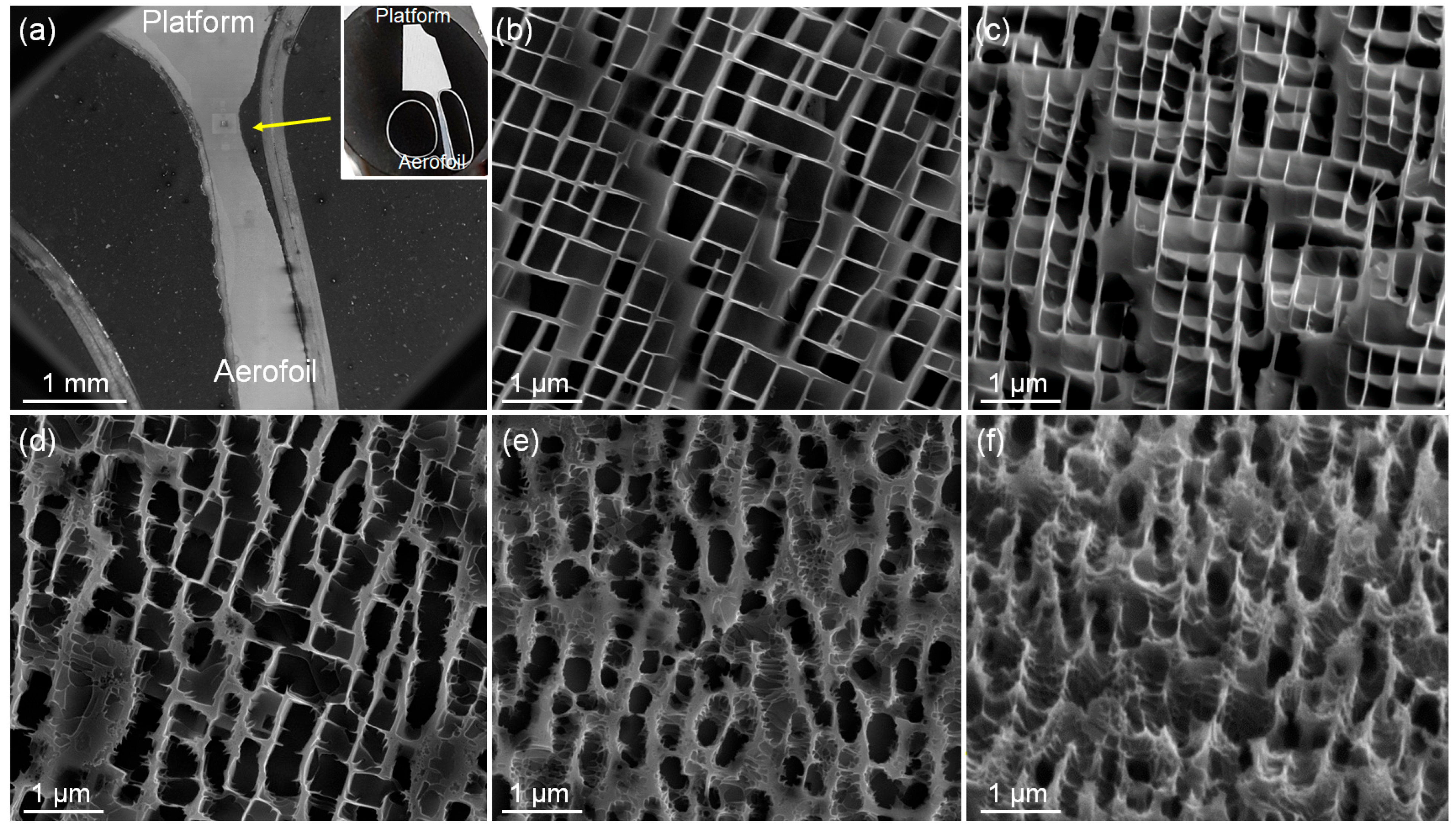
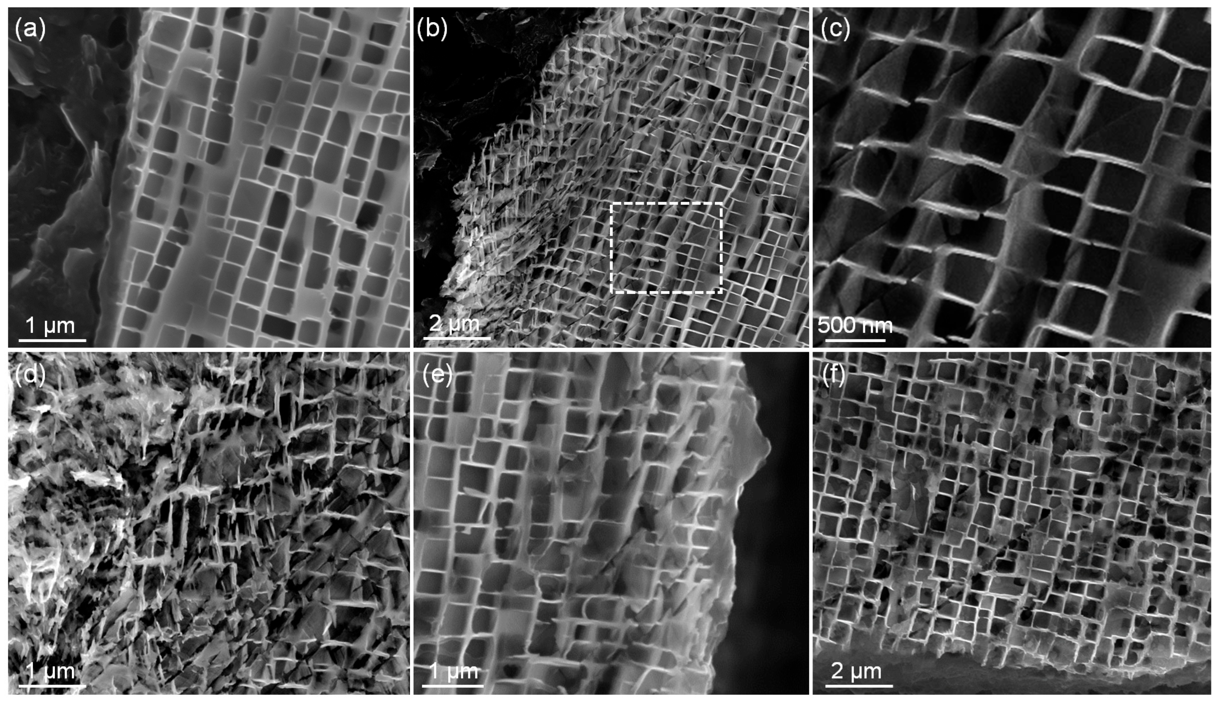
3.1. Observation of the Surface with a Different Contrast

Figure 1 shows the location of an interested region on a nickel-based single-crystal turbine blade. At the corner of the pressure (concave) surface of aerofoil and the platform of a blade (Figure 1a), a surface region with a different contrast of a few millimeters is frequently found. The area is visibly distinguishable even with the naked eye, as shown in Figure 1b.
To investigate this region, the section containing the corner was cut from the blade, ultrasonically cleaned in ethanol, and observed by SEM. Figure 2a is an SEM image of the region easily recognized due to the different contrast. Higher magnification observation was then conducted to examine the detailed microstructure. As the turbine blade was fully heat-treated, most areas in Figure 2a showed the typical microstructure composed of thin γ channels and γ’ precipitation. Due to the etchant (Kalling’s 2) used in this study, only γ’ precipitation is visible, as shown in Figure 2b. It should be emphasized that this typical microstructure of γ/γ’ was anticipated to be uniform across the entire blade. However, in the dark contrast region, an unexpected and distinctly different microstructure was observed (Figure 2c). The γ’ precipitates no longer retained their characteristic cubic morphology, instead appearing rounder with a less regular pattern. Most of all, the γ’ phase appeared partially dissolved or melted. In addition, as shown in Figure 2d, some lines are clearly visible. Compared with the typical region, the microstructure acquired in the dark contrast region is absolutely ‘abnormal’, indicating deterioration of the γ/γ’ phases.

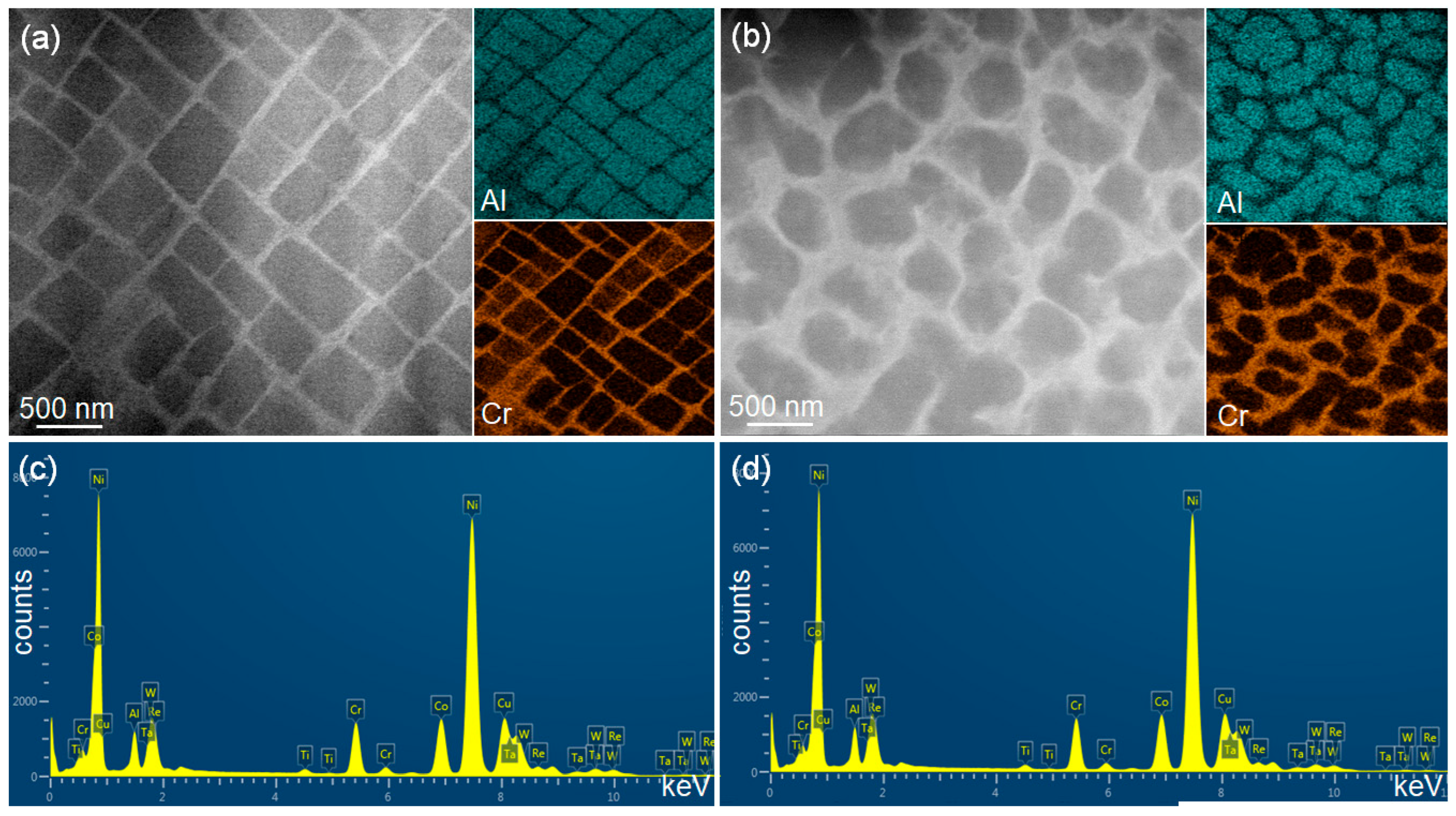
3.2. High Resolution Observation of the Abnormal Microstructure

To enable detailed analysis of the abnormal microstructure, the region containing the corner of aerofoil/platform was cut out, mounted in a conductive resin using a metal mounting clip, polished, and then etched. Figure 3a is a low magnification SEM image of the corner region, along with an insert photograph showing the polished and etched sample surface. It should be noted that the metallic clip used for mounting is visible near the aerofoil region in the image. As marked with an arrow in the image, the thinnest region is located near the boundary of the platform/aerofoil. Firstly, the upper part over the marked region, adjacent to the platform of the turbine blade, was observed. The region shows a typical microstructure of thin γ channels and γ’ (Figure 3b). It should be noted that all images in Figure 3b–f were acquired exactly at the same magnification of 50,000×. To enhance the visibility of the thin γ channels, the sample was tilted and observed as shown in Figure 3c. It is clear that the γ channels are thin and clear without any specific or additional precipitation inside the channels. The sample was then thoroughly scanned from the upper part (platform) toward the lower (aerofoil) of the marked region in Figure 3a. A gradual transition in microstructure was observed. As shown in Figure 3d, the regularity of the γ/γ’ morphology began to deteriorate progressively, without any distinct phase boundary or interface. Closer to the thinnest part of the section (as marked in Figure 3a), the microstructure exhibited a complete loss of regularity, which means that the typical microstructure of thin γ channels and cubic γ’ disappeared completely (Figure 3e). This is further confirmed by the tilted view image in Figure 3f, which clearly reveals the absence of thin γ channels. Although the observation area was originally in a fully heat-treated single-crystal turbine blade, the region clearly showed a distinguishable and abnormal microstructure. Then, as the SEM scanning progressed below the thinnest part of the section, the microstructure gradually began to recover. For example, the microstructure 1 mm below the thinnest region was almost the same as that in Figure 3d, and finally, when SEM scanning reached about 2 mm below the thinnest part, a typical microstructure (almost the same image as Figure 3b) was observed without any more abnormal microstructure. These results clearly indicate that the abnormal microstructure is confined to a highly localized region characterized by the most significant geometric transition in the turbine blade, specifically at the junction between the aerofoil and platform.

3.3. Comparison of TEM Images Acquired in Normal and Abnormal Regions

Instead of the expected microstructure of thin γ channels and γ’ precipitates in a fully heat-treated turbine blade, it is interesting to detect the abnormal microstructure. To enable a detailed comparison, two TEM samples were fabricated from representative normal and abnormal regions, respectively, by a FIB lift-out technique. Figure 4 presents the TEM images and TEM-EDX analysis of the two microstructures. Figure 4a shows the typical microstructure of the normal region, characterized by a regular γ channel (bright contrast due to heavier elements, such as tungsten, chromium, cobalt, and rhenium, which are strongly partitioned to γ, and γ’ precipitation (dark contrast due to lighter elements, such as aluminum and titanium) [6,7]. In contrast, as already shown in Figure 3e, the abnormal microstructure in Figure 4b clearly shows a different microstructure, in which the regularity of thin γ channels and γ’ are lost. This loss is further confirmed by STEM-EDX element maps, particularly for aluminum and chromium, which reveal a disrupted distribution pattern. Despite the morphological differences, the region remains composed of γ (bright contrast) and γ’ (dark contrast) phases. Therefore, to compare the main elements and the composition of γ’ in each region, STEM-EDX point analyses were conducted. Two representative spectra for the γ’ phase in the normal and abnormal regions are shown in Figure 4c and 4d, respectively. It should be emphasized that, regardless of the region, almost the same spectra were acquired (except for some peaks with slightly more counts). In other words, similar spectra for each alloying element were acquired on γ’ in the normal and γ’ in the abnormal region. Based on the point analysis, the composition of γ’ in each region was acquired and summarized in Table 1. The compositions of the main elements, such as aluminum and chromium, were slightly lower in the abnormal region, while the amounts of tungsten and rhenium were slightly higher in the region. It is important to understand the formation mechanism of the abnormal microstructure, and this will be discussed later.

4. Discussion

Several previous studies have reported microstructures similar to the transition area or the abnormal microstructure observed in this study. In an as-cast state, a comparable transitional microstructure (similar to Figure 2d) was reported throughout an entire single crystal sample after adding a small amount (about 0.1 wt%) of carbon [8], but the ‘not well-developed’ structure evolved into a typical microstructure after heat treatment. In contrast, the abnormal microstructure in this study was observed even after full heat treatment, and importantly, no carbon was added to the alloy. Furthermore, the abnormal microstructure was confined specifically to the corner of the aerofoil/platform of the turbine blade. Another study also showed a similar transitional microstructure in CMSX-2 alloys (Ni base-8 wt% Cr-8 W-6 Ta-5.6 Al-4.6 Co-1 Ti-0.6 Mo) when aged and then subjected to extremely slow cooling (0.02 °C/s) [9]. Such slow cooing indicates that a sample can stay for a longer time at higher temperatures, which means that even slow diffusion elements in nickel-based matrix, such as Re and W, can diffuse and allow a homogeneous chemical composition. This is important because the γ’ precipitation occurs in the solid state, which is dominated by the diffusion of alloying elements. Nevertheless, even under these conditions, a normal microstructure was obtained when samples were cooled at a more practical rate of 0.2 °C/s, which approximates the cooling conditions used in this study following a well-established processing schedule (which was not slowly cooled but normally cooled). Therefore, while prior studies [8,9] describe microstructures resembling the transition region observed in this study, they do not match the abnormal microstructure. It should be mentioned that, based on the currently published literature, no studies show the abnormal microstructure observed at a nickel-based single-crystal turbine blade after full heat treatment.
This leads to a critical question: how did the abnormal microstructure form extremely locally, i.e., only at the corner of the aerofoil/platform in a heat-treated turbine blade? Thermodynamically, it is more feasible for a normal γ/γ’ microstructure to degrade into an abnormal one than for the reverse to occur. In addition, the abnormal region formed gradually without any sharp interface within the main grain and any defect grain, such as recrystallized or stray grains [7] or secondary phases, such as topologically closed-packed phases (TCPs) [10]. Therefore, these findings indicate that the abnormal microstructure did not form by direct precipitation but developed gradually from the normal microstructure.
One possibility is that the abnormal region corresponds to the interdendritic region, which differs from the dendrite core in its γ/γ’ morphology [11]. This might suggest that some interdendritic regions survived the casting and the heat treatment processes and formed the abnormal region. However, the turbine blades in this study underwent full solutioning and aging heat treatments by a well-established schedule, which means that dendritic structures as well as microsegregation were generally removed. Nonetheless, it should be mentioned that the interdendritic regions might survive locally even after the heat treatment. However, no extended γ’ precipitation, which is typical evidence of remaining interdendritic zones, was seen in this area after the solutioning process. Furthermore, the size of the abnormal region (about 2 mm) far exceeds the usual scale of interdendritic areas (from about 100~200 µm up to 500 µm) [10], and most of all, the abnormal microstructure was only observed at the corner of the aerofoil/platform while the interdendritic region exists throughout an as-cast whole turbine blade, which indicates that the abnormal region was not the interdendritic one.
Another hypothesis involves a high temperature exposure during heat treatment, which may induce the initial stage of incipient melting or the degradation of regular microstructures. However, the γ’ precipitates would exhibit a rounder morphology throughout the entire sample if this were the case [12]. Furthermore, as the solutioning process should be performed below the melting temperature, there is a well-established solutioning window, which makes γ the only stable phase without any melting [1]. The turbine blades in this study were solutioned within the window and then underwent aging heat treatment at a much lower temperature (1100 °C). Therefore, this cannot explain the fact that the abnormal microstructure was detected just at the corner of the aerofoil/platform, not throughout the whole area of a turbine blade after heat treatment.
It is well established that the morphology of the γ’ phase in Ni-based single crystal superalloy turbine blades is generally influenced by various thermodynamic and kinetic factors, including alloy composition [13], long term service exposure [14], lattice misfit between the γ and γ’ phases [15,16,17,18], heat treatment [19,20], cooling rate [21,22], and particularly applied stress and creep environments [23,24]. Based on the manufacturing process and the microstructural observations in this study, another possible explanation for the formation of the abnormal microstructure is the presence of stress at high temperatures, which may have developed despite the fact that the turbine blades were only subjected to solutioning and aging heat treatments after casting, making the introduction of additional plastic deformation unlikely. This phenomenon is similar to creep behavior because a similar microstructure has been reported in creep-tested and additionally heat-treated samples [25,26]. However, it should be noted that even though an early-stage creep-tested sample showed a groove/ledge microstructure caused by dislocations at the interface of γ/γ’, which is similar to the transition area in this study [25], creep-tested blades typically show a rafted microstructure along one specific direction [27,28,29,30,31]. In contrast, the abnormal microstructure observed in this study was not oriented along any specific direction, which distinguishes it clearly from the characteristic rafted structure. Under low stresses, dislocations are unable to penetrate the γ’ phase and consequently tend to be piled up at the interface of γ/γ’. However, as shown in previous research [32], higher stress and/or higher temperature conditions enable dislocations to pass through the γ’ phase, resulting in the formation of a rafted microstructure or at least slip lines within the γ’ phase. For the slip through the γ’, a significant amount of stress is required to overcome barriers, such as local Orowan resistance, misfit stress, solid solution resistance, and resistance of other dislocations [33]. As a result, slip lines or rafted microstructures can be visible when these conditions are met.
To explore this possibility, the sample shown in Figure 2a was thoroughly scanned at high magnifications to detect the presence of any slip lines. Most regions in Figure 2a show the normal microstructure of thin γ channels and γ’, as shown in Figure 5a. It should be emphasized that near the surface in contact with the mounting resin (Figure 5a), there is no line or distortion of the normal microstructure. However, along the suction (convex) surface of the aerofoil, specific microstructures were observed as shown in Figure 5b. A higher magnification image at the marked region in Figure 5b, where the starting point of the specific microstructure was observed, clearly shows that there are several slip lines (Figure 5c). In addition, the lines indicate that the slip occurred in the γ’ phase as well as the γ matrix. Concentrating on the γ phase, it is clearly visible that thin γ channels were misaligned due to the slip, which suggests that the slip behavior occurred after the formation of thin γ channels, in other words, after γ’ precipitation. In addition, there was another region showing severe deformation as well as slip lines along the suction surface (Figure 5d). It should be mentioned that all micrographs in Figure 5a–d were acquired from the same suction surface of an aerofoil within a few millimeters of each other, which excludes any possibility of any additional local deformation process, such as machining or grinding during a manufacturing process.
To further examine the possibility of local deformation along only one side of the aerofoil, the opposite side (pressure surface) to the suction surface was also observed. Slip lines were identified on the pressure (concave) surface of the aerofoil as well (Figure 5e), which indicates that the slip occurred along both sides of the aerofoil. In addition, the slip lines were also observed at the bottom surface of the platform in Figure 2a (Figure 5f). Based on these observation results, it is concluded that the slip behavior occurred near and at the region showing the abnormal microstructure. However, it is important to note that the slip lines were observed only within about 10 µm from the surface, while the abnormal microstructure was continuously observed in the surface to a depth of more than 1000 µm. Even though the slip lines may not fully explain the formation mechanism, it is certain that some stresses definitely exist near the abnormal microstructure region.
The turbine blades in this study were just heat-treated after casting without any external mechanical load. Nevertheless, there are several mechanisms that could generate internal stresses during casting. Clearly, the difference in thermal contraction of γ and γ’ can cause residual stresses in heat-treated nickel-based superalloys [34]. In addition, the negative misfit of γ and γ’ is known to produce misfit stresses of about 500 MPa [25,33]. Most significantly, high thermal stresses of about 490 MPa can develop due to the differential thermal expansion coefficients of the solidifying casting components and the solid mold shell [35,36,37,38]. However, although it is generally assumed that the stresses of over 1 GPa generated during casting are, probably, completely released throughout the entire turbine blade during heat treatment (solutioning), in certain regions, especially the corner of the aerofoil/platform, which is believed to be exposed to the highest stress due to the geometry change, some stresses are probably not completely released. Therefore, some stresses may exist even in the heat-treated blades. In addition, the presence of slip lines, which formed after γ’ precipitation, was confirmed in this study. This observation result suggests that the abnormal region might have some stress, and most of all, it has been exposed to a high enough temperature during aging time to promote the diffusion of heavier elements, such as tungsten and rhenium. This combination of stress, temperature, and time can significantly alter the microstructure of metallic materials, which is analogous to creep degradation. It should be emphasized that, in the absence of sufficient residual thermal stress, the typical microstructure composed of thin γ channels and cubic γ’ would be expected throughout the turbine blade without any region showing the stress-induced microstructural degradation after the heat treatment. The observed microstructural deterioration suggests that, even though the specimen in this study was only cast and heat-treated using a well-established schedule, it was consequently not exposed to actual creep conditions, and the abnormal microstructure could be formed by a combination of conditions to release local stresses at high enough temperature for dislocation movement during aging and cooling.
Finally, it should be mentioned that while the mechanical properties were not dealt with in this study, it is evident that the abnormal microstructure definitely deteriorates the mechanical properties due to the reduced γ’ volume fraction in the abnormal region compared to the optimum value of about 70% in normal areas [20,39] as well as the almost round-shaped (in 2D) morphology of γ’ and thicker γ channels, which have an effect of dislocation movement along the boundary of γ’/γ and within γ channels [1,24]. It is therefore imperative for further study to measure actual mechanical properties influenced by residual stresses concentrated at the corner of the aerofoil/platform and to mitigate such abnormal microstructures to ensure the performance of turbine blades.

5. Summary

Electron microscopy revealed regions of distinct visual contrast near the corner of the aerofoil/platform of Ni-based single-crystal turbine blades. These regions showed significantly different surface features compared to the surrounding areas, such as the loss of the typical cubic morphology of the γ’ phase. The γ’ precipitates appeared partially dissolved or melted, which was abnormal to the usual observations after a well-established solutioning and aging heat treatment process. Cross-sectional SEM and TEM observation and analysis confirmed that the majority of the turbine blade maintained a normal microstructure characterized by thin and regular γ channels and finely precipitated γ’. In contrast, the corner region lost the regularity; in other words, it was composed of irregular γ and γ’ precipitates with slight compositional deviations, particularly in aluminum, chromium, and more prominently, tungsten and rhenium. High magnification images of the corner region showed severe deformation and slip lines along the surface of the aerofoil and even in the platform area. These findings suggested that the abnormal microstructure probably resulted from stress-induced microstructure degradation to release local residual stress at a high enough temperature during the heat treatment process.
Finally, it should be mentioned that while the presence of stress was definitely shown through the observed slip lines and severely deformed areas, the origin of this stress remains uncertain. Since the turbine blades in this study were fully heat-treated, further study on any residual stress that may be generated during casting, heat treatment, or cooling is required.

Author Contributions

Conceptualization, development of the methodology and analysis of the data by K.P.; Discussion by K.P., P.W. and J.D.; Writing and review by K.P., P.W. and J.D. All authors have read and agreed to the published version of the manuscript.

Funding

This work was supported by the UK Engineering and Physical Sciences Research Council (EPSRC) grant EP/T018518/1.

Data Availability Statement

The original contributions presented in this study are included in the article material. Further inquiries can be directed to the corresponding author.

Acknowledgments

The provision of evaluation test pieces by Rolls-Royce plc. is acknowledged.

Conflicts of Interest

The authors declare no conflicts of interest.

References

  1. Reed, R.C. The Superalloys: Fundamentals and Applications; Cambridge University Press: Cambridge, UK, 2006. [Google Scholar]
  2. Hachet, G.; Caillard, D.; Ventelon, L.; Clouet, E. Mobility of screw dislocation in BCC tungsten at high temperature in presence of carbon. Acta Mater. 2022, 222, 117440. [Google Scholar] [CrossRef]
  3. Gurrutxaga-Lerma, B. How strong is the temperature increase due to a moving dislocation? Int. J. Solids Struct. 2017, 108, 263–274. [Google Scholar] [CrossRef]
  4. Le, K.C.; Tran, T.M.; Langer, J.S. Thermodynamic dislocation theory of high-temperature deformation in aluminum and steel. Phys. Rev. E 2017, 96, 013004. [Google Scholar] [CrossRef]
  5. Brewster, G.; D’Souza, N.; Ryder, K.S.; Simmonds, S.; Dong, H.B. Mechanism for Formation of Surface Scale during Directional Solidification of Ni-Base Superalloys. Metall. Mater. Trans. A 2012, 43, 1288–1302. [Google Scholar] [CrossRef]
  6. Park, K.; Withey, P. Compositions of Gamma and Gamma Prime Phases in an As-Cast Nickel-Based Single Crystal Superalloy Turbine Blade. Crystals 2022, 12, 299. [Google Scholar] [CrossRef]
  7. Kim, K.; Withey, P. Detection of Rhenium-Rich Particles at Grain Boundaries in Nickel-Base Superalloy Turbine Blades. Mater. Trans. 2016, 57, 1698–1706. [Google Scholar] [CrossRef]
  8. Yu, Z.H.; Qiang, J.F.; Zhang, J.; Liu, L. Microstructure evolution during heat treatment of superalloys loaded with different amounts of carbon. J. Mater. Res. 2015, 30, 2064–2072. [Google Scholar] [CrossRef]
  9. Grosdidier, T.; Hazotte, A.; Simon, A. Precipitation and dissolution processes in Υ/Υ′ single crystal nickel-based superalloys. Mater. Sci. Eng. A 1998, 256, 183–196. [Google Scholar] [CrossRef]
  10. KeeHyun, P.; Paul, W. Observation of the Dissolution of Topologically Close Packed Phases by an Additional Heat Treatment in Third Generation Nickel-Based Single Crystal Superalloy Turbine Blades. Adv. Eng. Mater. 2018, 20, 1700987. [Google Scholar] [CrossRef]
  11. Rakoczy, Ł.; Milkovič, O.; Rutkowski, B.; Cygan, R.; Grudzień-Rakoczy, M.; Kromka, F.; Zielińska-Lipiec, A. Characterization of γ′ Precipitates in Cast Ni-Based Superalloy and Their Behaviour at High-Homologous Temperatures Studied by TEM and in Situ XRD. Materials 2020, 13, 2397. [Google Scholar] [CrossRef]
  12. Wang, T.Y.; Wang, X.M.; Zhao, Z.H.; Zhang, Z. Dissolution behaviour of the Υ′ precipitates in two kinds of Ni-based superalloys. Mater. High Temp. 2016, 33, 51–57. [Google Scholar] [CrossRef]
  13. Ye, L.; Liu, F.; Dong, H.; Ouyang, X.; Xiao, X.; Tan, L.; Huang, L. Investigation on the Microstructure and Mechanical Properties of Ni-Based Superalloy with Scandium. Metals 2023, 13, 611. [Google Scholar] [CrossRef]
  14. Saenarjhan, N.; Kiatwisarnkij, N.; Korthamniwet, W.; Lothongkum, G.; Rojhirunsakool, T.; Nisaratanaporn, E.; Horňak, P.; Wangyao, P. Development of morphology and lattice misfit in modified Ni-base superalloy with Al, Co and Ni additions. Mater. Test. 2023, 65, 1179–1189. [Google Scholar] [CrossRef]
  15. Yoo, Y.S.; Yoon, D.Y.; Henry, M.F. The effect of elastic misfit strain on the morphological evolution of γ’-precipitates in a model Ni-base superalloy. Met. Mater. 1995, 1, 47–61. [Google Scholar] [CrossRef]
  16. Chang, J.C.; Allen, S.M. Elstic energy changes accompanying gamma-prime rafting in nickel-base superalloys. J. Mater. Res. 1991, 6, 1843–1855. [Google Scholar] [CrossRef]
  17. Saito, T.; Harada, H.; Osawa, M.; Yokokawa, T.; Kawagishi, K.; Suzuki, S. Elastic modulus of tie-lined gamma and gamma prime phases of 6th generation Ni-base single crystal superalloy. Mater. Sci. Eng. A 2025, 941, 148410. [Google Scholar] [CrossRef]
  18. Parsa, A.B.; Wollgramm, P.; Buck, H.; Somsen, C.; Kostka, A.; Povstugar, I.; Choi, P.-P.; Raabe, D.; Dlouhy, A.; Müller, J.; et al. Advanced Scale Bridging Microstructure Analysis of Single Crystal Ni-Base Superalloys. Adv. Eng. Mater. 2015, 17, 216–230. [Google Scholar] [CrossRef]
  19. Saito, T.; Chen, Y.-T.; Takata, Y.; Kawagishi, K.; Hsu, W.-C.; Yeh, A.-C.; Murakami, H. Effect of Heat Treatments on the Microstructural Evolution of a Single Crystal High-Entropy Superalloy. Metals 2020, 10, 1600. [Google Scholar] [CrossRef]
  20. Awais, M.; Hixson, W.R.; Victor, Q.; O’Neal, C.; Ilavsky, J.; Coakley, J. Microstructure Evolution of a Multimodal Gamma-Prime Ni-Based Superalloy Characterized by In Situ Diffraction. Metall. Mater. Trans. A 2023, 54, 2311–2319. [Google Scholar] [CrossRef]
  21. Feng, Z.; Wen, Z.; Lu, G.; Zhao, Y. Influence of Cooling Scenarios on the Evolution of Microstructures in Nickel-Based Single Crystal Superalloys. Crystals 2022, 12, 74. [Google Scholar] [CrossRef]
  22. Wang, H.; Liu, D.; Wang, J.; Yang, Y.; Rao, H.; Wang, H.; Nan, J.; Wang, L. Study on the Evolution of the γ′ Phase and Grain Boundaries in Nickel-Based Superalloy during Interrupted Continuous Cooling. Crystals 2021, 11, 1464. [Google Scholar] [CrossRef]
  23. Nathal, M.V.; Ebert, L.J. Gamma prime shape changes during creep of a nickel-base superalloy. Scr. Metall. 1983, 17, 1151–1154. [Google Scholar] [CrossRef]
  24. Xu, R.; Li, Y.; Yu, H. Microstructure Evolution and Dislocation Mechanism of a Third-Generation Single-Crystal Ni-Based Superalloy during Creep at 1170 °C. Materials 2023, 16, 5166. [Google Scholar] [CrossRef]
  25. Parsa, A.B.; Wollgramm, P.; Buck, H.; Kostka, A.; Somsen, C.; Dlouhy, A.; Eggeler, G. Ledges and grooves at γ/γ′ interfaces of single crystal superalloys. Acta Mater. 2015, 90, 105–117. [Google Scholar] [CrossRef]
  26. Giraud, R.; Hervier, Z.; Cormier, J.; Saint-Martin, G.; Hamon, F.; Milhet, X.; Mendez, J. Strain Effect on the γ′ Dissolution at High Temperatures of a Nickel-Based Single Crystal Superalloy. Metall. Mater. Trans. A-Phys. Metall. Mater. Sci. 2013, 44A, 131–146. [Google Scholar] [CrossRef]
  27. Ren, W.L.; Niu, C.L.; Ding, B.; Zhong, Y.B.; Yu, J.B.; Ren, Z.M.; Liu, W.Q.; Ren, L.P.; Liaw, P.K. Improvement in creep life of a nickel-based single-crystal superalloy via composition homogeneity on the multiscales by magnetic-field-assisted directional solidification. Sci. Rep. 2018, 8, 17. [Google Scholar] [CrossRef]
  28. Tang, Y.T.; D’Souza, N.; Roebuck, B.; Karamched, P.; Panwisawas, C.; Collins, D.M. Ultra-high temperature deformation in a single crystal superalloy: Mesoscale process simulation and micromechanisms. Acta Mater. 2021, 203, 116468. [Google Scholar] [CrossRef]
  29. Kamaraj, M. Rafting in single crystal nickel-base superalloys—An overview. Sadhana 2003, 28, 115–128. [Google Scholar] [CrossRef]
  30. Cao, L.; Wollgramm, P.; Bürger, D.; Kostka, A.; Cailletaud, G.; Eggeler, G. How evolving multiaxial stress states affect the kinetics of rafting during creep of single crystal Ni-base superalloys. Acta Mater. 2018, 158, 381–392. [Google Scholar] [CrossRef]
  31. Gamanov, S.; Dlouhy, A.; Bürger, D.; Eggeler, G.; Thome, P. Evolution of local misorientations in the γ/γ’-microstructure of single crystal superalloys during creep studied with the rotation vector baseline (RVB) EBSD method. Microsc. Res. Tech. 2024, 87, 516–533. [Google Scholar] [CrossRef]
  32. Wu, X.; Makineni, S.K.; Liebscher, C.H.; Dehm, G.; Rezaei Mianroodi, J.; Shanthraj, P.; Svendsen, B.; Bürger, D.; Eggeler, G.; Raabe, D.; et al. Unveiling the Re effect in Ni-based single crystal superalloys. Nat. Commun. 2020, 11, 389. [Google Scholar] [CrossRef] [PubMed]
  33. Pollock, T.M.; Argon, A.S. Creep resistance of CMSX-3 nickel base superalloy single crystals. Acta Metall. Mater. 1992, 40, 1–30. [Google Scholar] [CrossRef]
  34. Epishin, A.; Link, T.; Brückner, U.; Fedelich, B.; Portella, P. Effects of segregation in nickel-base superalloys: Dendritic stresses. In Proceedings of the Superalloys 2004, Champion, PA, USA, 19–23 September 2004; pp. 537–543. [Google Scholar]
  35. Sengupta, J.; Thomas, B.G.; Wells, M.A. The use of water cooling during the continuous casting of steel and aluminum alloys. Metall. Mater. Trans. A 2005, 36, 187–204. [Google Scholar] [CrossRef]
  36. Nekahi, S.; Vaferi, K.; Vajdi, M.; Sadegh Moghanlou, F.; Shahedi Asl, M.; Shokouhimehr, M. A numerical approach to the heat transfer and thermal stress in a gas turbine stator blade made of HfB2. Ceram. Int. 2019, 45, 24060–24069. [Google Scholar] [CrossRef]
  37. Xu, W.; Wang, F.; Ma, D.; Zhu, X.; Li, D.; Bührig-Polaczek, A. Sliver defect formation in single crystal Ni-based superalloy castings. Mater. Des. 2020, 196, 109138. [Google Scholar] [CrossRef]
  38. Aveson, J.W.; Tennant, P.A.; Foss, B.J.; Shollock, B.A.; Stone, H.J.; D’Souza, N. On the origin of sliver defects in single crystal investment castings. Acta Mater. 2013, 61, 5162–5171. [Google Scholar] [CrossRef]
  39. Kang, S.K.; Benn, R.C. Microstructural development in high volume fraction gamma prime Ni-base oxide-dispersion-strengthened superalloys. MTA 1985, 16, 1285–1294. [Google Scholar] [CrossRef]
Figure 1. A turbine blade containing an abnormal microstructure: (a) schematic diagram of a turbine blade and (b) photo of a region with dark contrast on the surface near the corner of aerofoil/platform at the marked region in (a).
Crystals 15 00553 g001
Figure 2. SEM images acquired from a normal and an abnormal region: (a) low magnification SEM image of the dark contrast region at the marked region in Figure 1b, (b) normal microstructure acquired at the top or bottom part in panel (a), and (c,d) abnormal microstructure inside the dark contrast region (c) and a higher magnification image at the marked region in (c). The arrows in (d) indicate some slip lines.
Crystals 15 00553 g002
Figure 3. SEM images of normal and abnormal microstructures: (a) low magnification SEM image near the corner of the aerofoil/platform with an insert photo showing the cut blade mounted, (b,c) normal microstructure acquired near the platform or the bottom part of aerofoil in the (a) plan view (b) and tilting view (c,d) transition area between the normal and the abnormal regions, and (e,f) abnormal microstructure in the plan view (e) and tilting view (f). Note that SEM images in (bf) were acquired at the same magnification.
Crystals 15 00553 g003
Figure 4. STEM observation and STEM-EDX analysis: (a,b) STEM-HAADF image and corresponding STEM-EDX element maps of aluminum (cyan) and chromium (orange) in the normal (a) and the abnormal (b) regions and (c,d) STEM-EDX point analysis on the γ’ in the normal (c) and the abnormal (d), respectively. Images of normal and abnormal microstructures: (a) low magnification SEM image near the corner.
Crystals 15 00553 g004
Figure 5. SEM images of slip bands: (a) normal microstructure on the pressure (concave) surface of a turbine blade, (b,c) near the abnormal region showing slip lines at a relatively low magnification (b) and a magnified image at the marked region (c,d) another region showing severely distorted microstructure near the surface, and (e,f) slip lines on the suction (convex) surface (e) and the platform region (f) of a blade.
Crystals 15 00553 g005
Table 1. Compositions (in wt.%) of raw material [1] and γ’ phases measured in a normal microstructure and an abnormal region, respectively, by STEM-EDX.
AlTiCrCoMoHfTaWReNi
Raw5.61.06.59.60.60.16.56.43.0Bal.
Normal6.01.52.77.50.40.07.76.10.5Bal.
Abnormal5.61.32.57.20.30.07.36.80.6Bal.
Disclaimer/Publisher’s Note: The statements, opinions and data contained in all publications are solely those of the individual author(s) and contributor(s) and not of MDPI and/or the editor(s). MDPI and/or the editor(s) disclaim responsibility for any injury to people or property resulting from any ideas, methods, instructions or products referred to in the content.

