1. Introduction
Acoustic metasurfaces are subwavelength artificial structures engineered to control the propagation of sound waves in unprecedented ways. As a subclass of metamaterials, they enable novel wave phenomena, such as negative refraction [
1,
2], sub-diffraction-limited imaging [
3], and acoustic cloaking [
4], which are not achievable in natural materials. By tailoring unit cell geometries, acoustic metasurfaces allow for precise modulation of phase, amplitude, and direction, unlocking a wide range of applications in beam steering, imaging, noise control, and underwater communication [
5,
6,
7].
Early research on acoustic metasurfaces focused primarily on reflective and gradient-index configurations that demonstrated functionalities, such as asymmetric transmission [
8], anomalous reflection [
9], and subwavelength diffraction control [
10]. Labyrinthine metasurfaces emerged as effective designs for compact phase delay engineering, providing full-range 0–2π modulation through internally elongated acoustic paths [
11,
12,
13]. Subwavelength diffractive and coding metasurfaces further enabled static wavefront shaping [
14,
15], although these systems were often constrained to narrow frequency ranges or single functions. To expand functionality and bandwidth, recent studies have employed topology optimization, multilayer structures, and programmable or active elements [
16,
17,
18,
19,
20,
21,
22]. For example, Guo and Cheng [
16] introduced topology-optimized transmissive metasurfaces using a level-set method, while Zuo et al. [
17] and Chen and Hu [
18] utilized layered labyrinthine configurations for broadband signal manipulation. Ni et al. [
19] proposed high-efficiency acoustic meta-gratings, and Xia et al. [
20] developed dual-layer metasurfaces for tunable asymmetric focusing. Other advancements include flexible metafiber bundles [
21] and membrane-based tunable water–air transmission interfaces [
22].
In parallel, several recent efforts have explored metasurface designs specifically targeting water–air sound transmission enhancement. Bok et al. [
23,
24] achieved extraordinary cross-media acoustic transmission using optimized hole-array and structural coupling strategies. Related work introduced discrete metasurfaces to overcome extreme acoustic impedance mismatches [
25] and membrane-sealed bubble designs for underwater acoustics [
26]. Further studies have pushed acoustic metasurface concepts into emerging areas, such as three-dimensional beamforming using curved coding metasurfaces [
27], programmable mechanical metastructures with constant-force units [
28], Rayleigh surface wave modulation via reconfigurable elastic designs [
29], and ultra-broadband labyrinthine mufflers for ventilation and noise control [
26]. Additional innovations include Janus-coded metasurfaces breaking reflection symmetry [
30] and acoustic cloaks based on anisotropic media [
4].
Despite this progress, many state-of-the-art metasurfaces remain limited by structural complexity, narrowband performance, or function-specific design. A practical challenge remains in realizing passive, transmissive metasurfaces that simultaneously provide broadband response, high-efficiency transmission, full 0–2π phase modulation, and multifunctional wavefront control in a compact and fabricable structure.
To address this, we propose a grating-type labyrinthine acoustic metasurface capable of achieving the following five key functionalities: full-range phase modulation, anomalous refraction, planar focusing, cylindrical-to-plane wave conversion, and cylindrical wave focusing. The phase delay is controlled by tuning the tooth length of each unit cell in a periodic grating layout. Finite element simulations confirm that the metasurface achieves stable phase responses and transmission coefficients exceeding 0.8 over a 400 Hz range centered at 4000 Hz.
This work bridges the gap between simplicity and functionality by offering a structurally straightforward yet highly effective platform for broadband acoustic wave manipulation. The proposed metasurface complements and extends prior reflective, reconfigurable, and topology-optimized designs, offering new opportunities for integration into compact, multifunctional acoustic systems.
2. Structural Design and Method
The proposed acoustic metasurface is constructed in the
x–y plane based on a grating-type labyrinthine configuration, enabling phase manipulation of transmitted acoustic waves through geometrical modulation. The grating-type structure is designed to be invariant in the out-of-plane direction, ensuring uniformity in its acoustic wave manipulation properties across the entire surface. As shown in
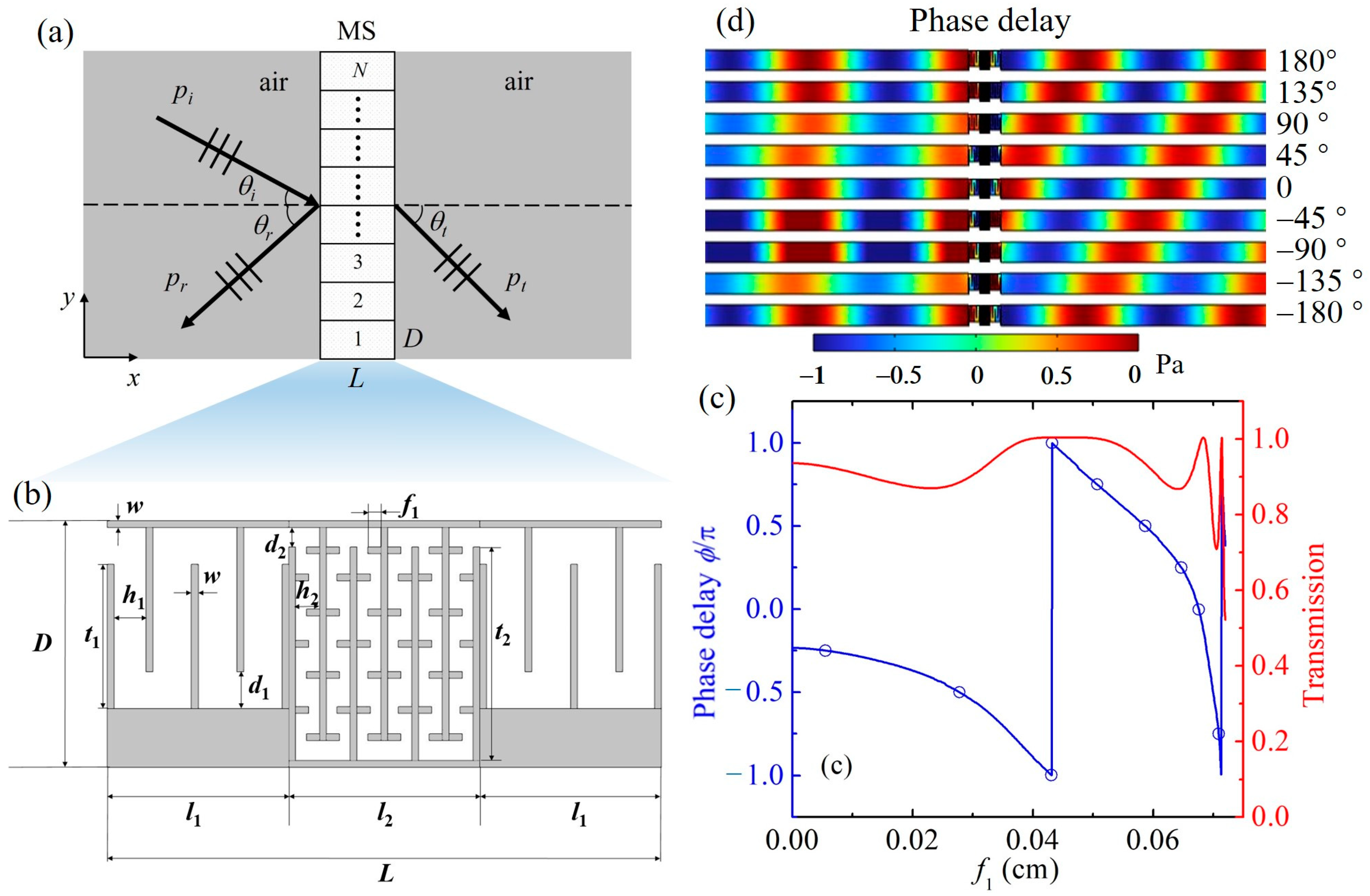
Figure 1a, the metasurface (denoted as MS) comprises an array of subwavelength unit cells arranged vertically along the
y-axis. When a plane acoustic wave,
pi, is normally or obliquely incident from the left medium (air), it partially reflects (
pr) and transmits (
pt) through the metasurface. The associated angles of incidence
θi, reflection
θr, and transmission
θt characterize the directional behavior of the wave interaction with the metasurface interface.
The geometric configuration of a single unit cell is detailed in
Figure 1b. The unit cell spans a total length,
L, composed of a central phase modulation region of length,
l2, and two symmetric impedance-matching sections on either side, each of length
l1. The height of the structure is represented by
D. The central region contains a periodic array of vertical teeth with a tunable length,
f1, which governs the effective acoustic path and thereby induces the desired phase shift in the transmitted wave. Additional geometric parameters include the tooth width,
w, tooth heights,
t1 and
t2, groove depths,
d1 and
d2, and channel widths,
h1 and
h2, all contributing to acoustic impedance characteristics and wave propagation behavior.
The metasurface material is composed of epoxy resin, characterized by its density of 1200 kg/m
3, Young’s modulus of 3.2 GPa, and Poisson’s ratio of 0.35, as indicated by the gray regions in the figure, while the white areas within the structure correspond to air-filled cavities. This composite design achieves impedance matching by carefully balancing the geometric and material properties of the structure. Specifically, the inclusion of dual outer layers ensures that the metasurface’s effective acoustic impedance closely approximates that of air, significantly reducing reflection and allowing for efficient transmission of incident energy. To ensure a high transmission coefficient, the characteristic impedance,
Z1, of the outer labyrinthine layer and the length,
l1, must satisfy the following equations [
31]:
In the equation,
Z0 and
Z2 represent the characteristic impedances of the background medium (air) and the inner grating structure, respectively, where
Z0 =
ρ0c0, with an air density of
ρ0 = 1.21 kg/m
3 and a sound speed of
c0 = 343 m/s, and
λ1 is the wavelength of the sound wave propagating through the outer labyrinth layer.
3. Results and Discussions
To systematically evaluate the functional capabilities of the proposed metasurface, this section presents a series of analyses beginning with the fundamental phase modulation performance and progressing to practical demonstrations of wavefront manipulation. The results are structured to validate the metasurface’s effectiveness in controlling acoustic wave propagation through anomalous refraction, planar focusing, and cylindrical-to-plane wave conversion. These functionalities are representative of common application scenarios in acoustic imaging, beam steering, and coherent sound shaping.
3.1. Phase Delay and Transmission Coefficient
The phase modulation and transmission characteristics of the metasurface were evaluated using finite element simulations in COMSOL Multiphysics at a working frequency of 4000 Hz. The geometry parameters of the grating-type labyrinthine metasurface are listed in
Table 1. At the design frequency of 4000 Hz, the wavelength in air is approximately 85.75 mm. The metasurface thickness along the wave propagation direction (
x-axis) is 16.84 mm, corresponding to ~0.196
λ. These electrical dimensions confirm the subwavelength compactness of the design in both transverse and axial directions.
Figure 1c shows the following simulated results: the blue curve represents the phase delay normalized by
π, and the red curve denotes the corresponding transmission coefficient as a function of the tunable tooth length,
f1. The metasurface exhibits full-range phase modulation from −
π to
π, indicating the capability for complete 0–2
π phase control. Throughout most of the
f1 tuning range, the transmission remains above 0.8, confirming that efficient wavefront manipulation can be achieved without significant energy loss.
Based on the results shown in
Figure 1c, nine representative metasurface unit cells were selected to uniformly span the full phase modulation range from −
π to
π. These units were chosen such that their corresponding tooth lengths,
f1, yield approximately equidistant phase delays across the entire range. The transmission phase delays of the selected unit cells were calculated through finite element simulations, and the results are illustrated in
Figure 1d. As shown, the retrieved phase delays closely match the theoretical targets, confirming that the nine units collectively provide the required phase coverage for wavefront manipulation applications.
To verify the impedance-matching performance of the metasurface, both theoretical and simulated acoustic impedance values were evaluated. The theoretical impedance of the outer labyrinthine layer was calculated using the effective impedance formula
Z =
ρc, based on the known material properties of the epoxy resin and the effective acoustic path geometry of the channel. The simulated impedance was retrieved from the COMSOL results by extracting the complex pressure,
p, and particle velocity,
v, at the input interface, using the ratio
Z =
p/
v. Based on Ref. [
32], the calculated impedance value of 2486 Pa·s/m closely matches the theoretical value of 2496 Pa·s/m based on Equation (1), with a deviation of only 0.4%. This close agreement confirms the effectiveness of the impedance-matching strategy employed in the unit cell design. This performance underscores its potential for a variety of advanced acoustic applications, including acoustic lenses, sound focusing systems, and noise control devices.
3.2. Acoustic Beam Steering Through Anomalous Refraction
One of the key objectives of this study is to verify that the proposed metasurface can precisely control the direction of transmitted acoustic wavefronts by introducing spatially varying phase gradients. To demonstrate this capability, we focused on the phenomenon of anomalous refraction, which serves as a canonical example of phase-gradient-based wavefront manipulation. By analyzing the transmitted angle and broadband performance under different frequencies, this section validates the metasurface’s ability to implement accurate and robust phase profiles—an essential prerequisite for its use in practical beam steering and directional acoustic systems.
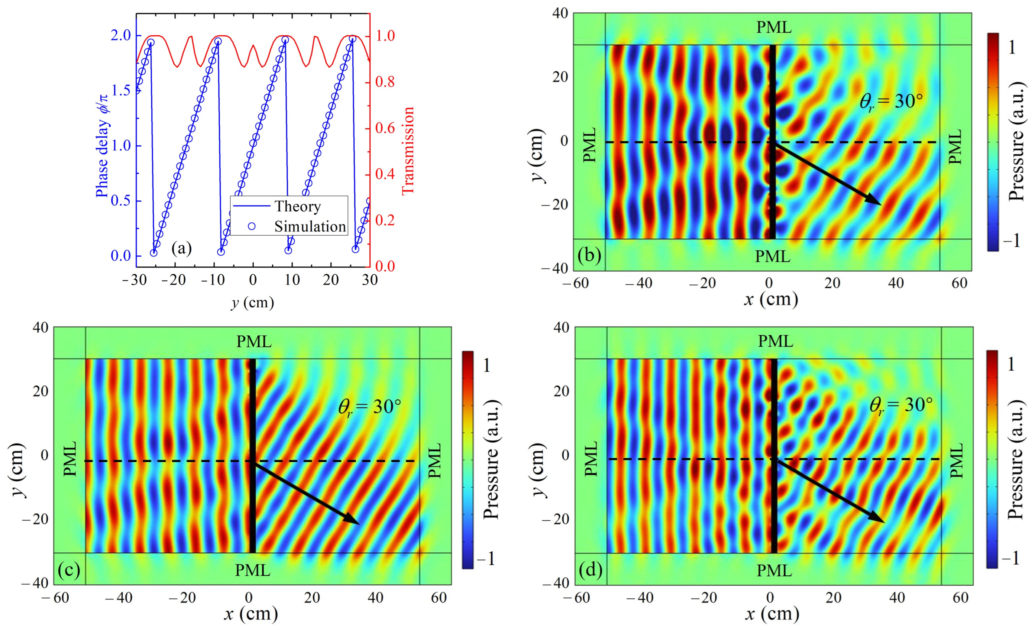
Anomalous refraction describes the deviation of transmitted acoustic waves from the trajectory expected by Snell’s law when they pass through specially designed interfaces. In acoustic metasurfaces, this phenomenon results from the deliberate incorporation of spatial phase gradients on the surface, which manipulate the wavefronts of incoming sound waves. According to the generalized Snell’s law, the local phase shift distribution introduced by the metasurface can significantly alter the angle of transmitted waves, enabling functionalities like beam steering, focusing, and sound redirection.
The phase delay distribution of the metasurface structure exhibiting anomalous refraction at coordinate
y must satisfy the following equation:
where
k0 is the wave number of the acoustic wave in air, and the pre-set acoustic deflection angle is
θ1 = 30°.
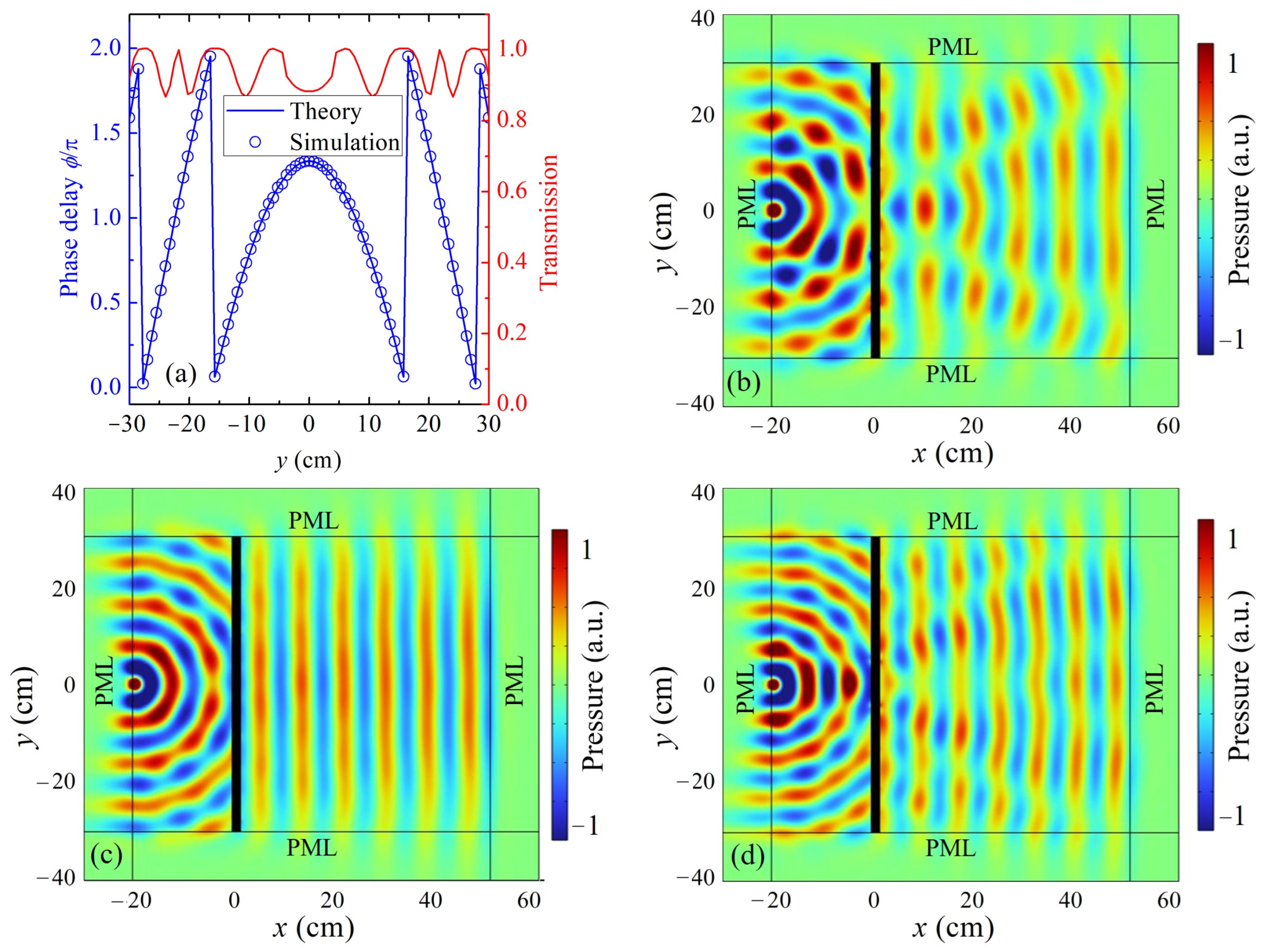
The required phase delay as a function of transverse position y was derived analytically and discretized across 81 unit cells.
Figure 2a presents the theoretical phase profile (blue line) alongside the numerically extracted phase delays (blue circles) for each unit. The strong agreement between the theoretical and simulated phase distributions demonstrates the accuracy of the phase modulation strategy. Furthermore, the red curve in
Figure 2a confirms that the transmission coefficient remains at a high value over the entire metasurface aperture, indicating low-loss performance. To assess the robustness of the metasurface design over a range of frequencies, full-wave simulations were conducted at 3600 Hz, 4000 Hz, and 4400 Hz. The resulting pressure field distributions are shown in
Figure 2b,
Figure 2c, and
Figure 2d, respectively. In each case, the normally incident plane wave is redirected at approximately
θr = 30°, consistent with the designed phase gradient. Despite small differences in interference patterns due to frequency variation, the refraction angle remains stable, confirming the metasurface’s ability to maintain efficient beam steering within this frequency window. These results highlight the metasurface’s broadband functionality, demonstrating reliable phase-controlled wavefront manipulation across a 400 Hz range centered at the design frequency. The compactness of the metasurface can be quantified by its electrical dimensions at the design frequency of 4000 Hz, where the acoustic wavelength in air is approximately 85.75 mm. The total height of the structure, composed of 81 discretized unit cells, is 607.5 mm, which corresponds to ~7.08
λ. The thickness of the metasurface along the
x-axis (wave propagation direction) is 16.84 mm, equivalent to ~0.196
λ. These subwavelength dimensions verify the compactness of the metasurface and highlight its potential for integration in broadband and miniaturized wavefront control systems.
3.3. Subwavelength Acoustic Focusing of Plane Waves
Building upon the phase modulation results in
Section 3.1 and the directional control demonstrated in
Section 3.2, this section investigates the metasurface’s capability to achieve subwavelength acoustic focusing—a functionally significant demonstration of wavefront shaping. Acoustic focusing enables the precise concentration of sound energy at a target location and is a key feature of metasurfaces. Unlike traditional curved lenses that rely on geometric curvature, the proposed planar metasurface achieves focusing by imposing spatially curved phase profiles across its surface. This approach confirms not only the structure’s wavefront manipulation capability, but also its potential for integration into compact, lightweight acoustic systems. The ability to perform efficient planar focusing validates the metasurface’s design flexibility and practical relevance in applications, such as medical ultrasound, nondestructive testing, and acoustic imaging, where miniaturized and broadband acoustic components are essential.
In this study, the grating-type metasurface was further refined to enable subwavelength focusing of acoustic waves. By adjusting the tooth length in accordance with a hyperbolic phase delay, the transmitted wavefronts were engineered to focus at a predetermined point in the near field. The necessary phase delay for each unit was determined based on the geometric distance to the focal point and applied through localized modifications of the tooth length.
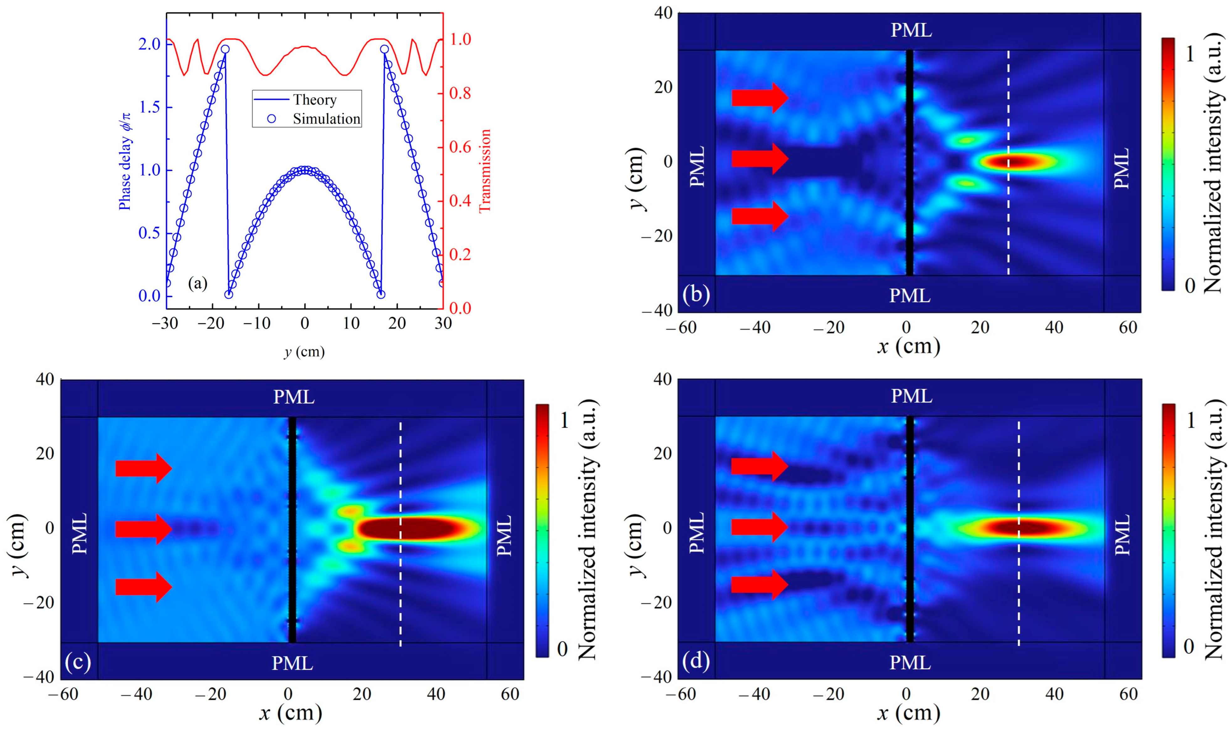
The metasurface was next configured to function as a flat acoustic lens. A hyperbolic phase distribution was designed to converge incident plane waves at a target focal length of 30 cm, governed by the following:
where
b = 30 cm denotes the focal length of the focusing metasurface.
Figure 3a presents the theoretical hyperbolic phase profile (blue line) and the corresponding simulated phase delays (blue circles), demonstrating excellent agreement between the designed and realized phase response. This consistency verifies the precision of the geometric modulation strategy for acoustic wavefront tailoring. To assess the focusing behavior across a range of operating frequencies, full-wave finite element simulations were conducted at 3600 Hz, 4000 Hz, and 4400 Hz. The resulting normalized acoustic intensity distributions are shown in
Figure 3b–d. In all three scenarios, incident plane waves are transformed into converging wavefronts, forming pronounced focal regions in the vicinity of the expected focal depth. Although slight displacements of the focal spot are observed due to frequency-dependent variations in the effective phase gradient, the energy concentration remains high and well-defined. These variations arise primarily from the wavelength-dependent scaling of the spatial phase profile, which leads to modest phase mismatches at off-design frequencies. Nevertheless, the focal shift is minor and does not degrade the integrity of the focusing performance.
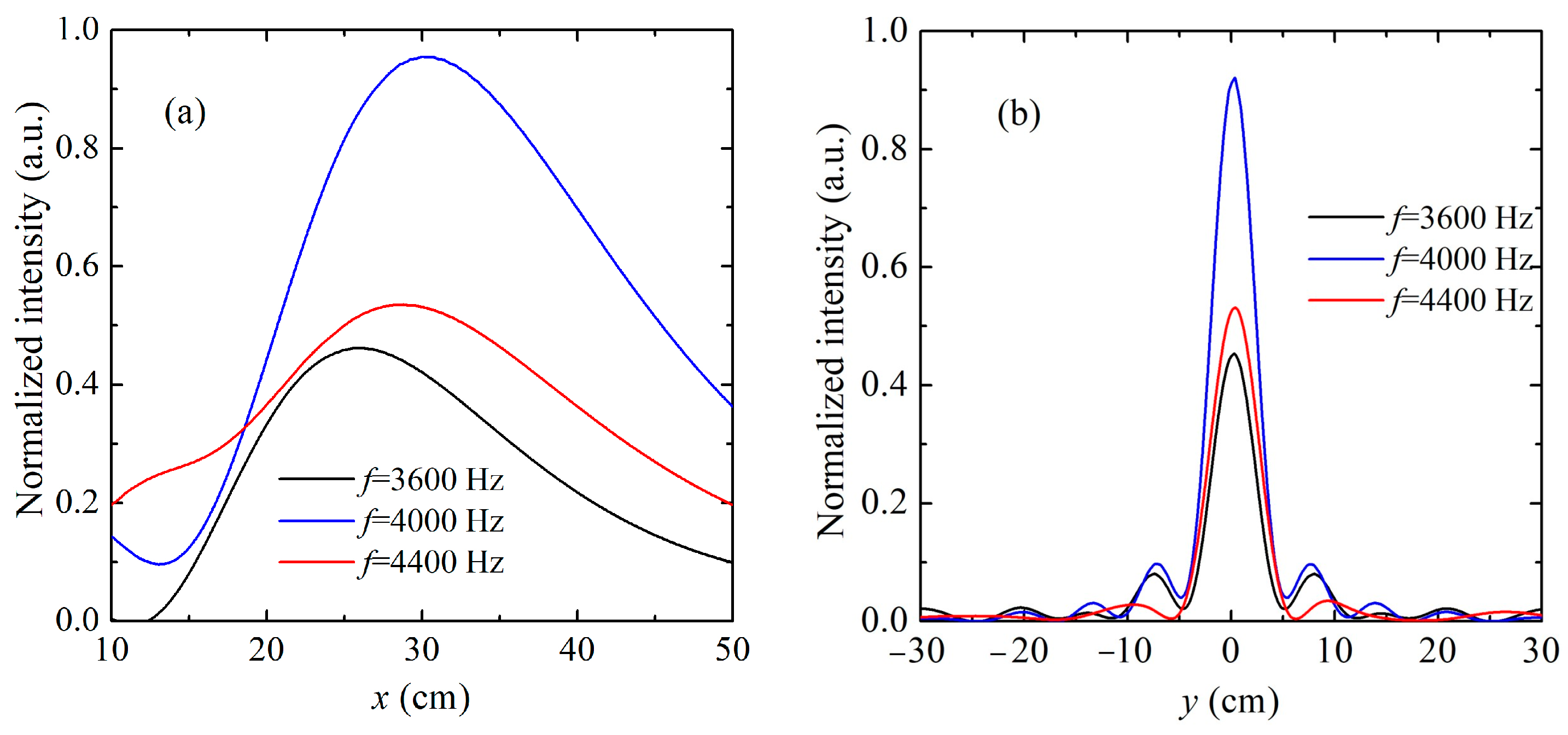
To further evaluate the focusing performance, the normalized acoustic intensity was extracted at the focal plane in both the axial (
x-direction) and transverse (
y-direction) dimensions, as shown in
Figure 4. In
Figure 4a, the axial intensity distributions for 3600 Hz, 4000 Hz, and 4400 Hz are plotted. At 4000 Hz, the peak intensity is observed near the designed focal length of 30 cm, indicating precise energy convergence. In contrast, at 3600 Hz and 4400 Hz, the peak positions shift slightly downstream and upstream, respectively, revealing a frequency-dependent focal displacement. Nevertheless, all three curves exhibit smooth, unimodal profiles with well-defined peaks, suggesting that effective energy localization is achieved despite the variation in wavelength.
Figure 4b shows the lateral intensity profiles at the focal plane for the three frequencies. At 4000 Hz, the intensity reaches a sharp maximum at the center (
y = 0), with low side lobes, indicating strong transverse confinement. The profiles at 3600 Hz and 4400 Hz also exhibit clear central peaks, albeit with broader main lobes and slightly elevated side lobes. These variations reflect mild degradation in lateral resolution at off-design frequencies but still maintain a clear focusing effect. Overall, the intensity analyses confirm that the proposed metasurface design maintains strong focusing characteristics across a range of frequencies. The lensing behavior is resilient to moderate frequency shifts, with only minor degradations in focal sharpness and position.
The compactness of the metasurface can be quantitatively described by its electrical dimensions at the design frequency of 4000 Hz, where the wavelength in air is approximately 85.75 mm. The total thickness of the metasurface along the wave propagation direction (x-axis) is 16.84 mm, corresponding to about 0.196λ, while the total height composed of 81 unit cells along the y-axis is 607.5 mm, or approximately 7.08λ. These dimensions confirm that the metasurface operates in a deep-subwavelength regime in the axial direction and remains compact relative to the wavelength, validating its suitability for integration into miniaturized acoustic systems.
3.4. Cylindrical-to-Plane Wave Conversion
In addition to plane wave manipulation, many practical acoustic systems involve point sources that generate cylindrical or spherical wavefronts. To demonstrate the versatility and robustness of the proposed metasurface under such conditions, we further focus on the following two representative functionalities: cylindrical-to-plane wave conversion and subwavelength focusing of cylindrical waves. These analyses are crucial for verifying that the metasurface can maintain effective phase modulation and high transmission performance even when interacting with curved wavefronts. Successful implementation of these functions confirms the structure’s applicability in real-world scenarios, such as acoustic beamforming, near-field imaging, and compact directive sound sources.
The conversion of cylindrical waves into plane waves is essential for improving the directionality and spatial coherence of acoustic fields, particularly in systems with point sources. Traditional acoustic elements often face challenges in achieving this conversion efficiently and compactly, primarily due to diffraction effects and impedance mismatches. In contrast, acoustic metasurfaces offer a robust solution by utilizing wavefront-shaping techniques that rely on local phase manipulation.
To transform spherical wavefronts into plane waves, we implemented a cylindrical-to-plane wave converter. The required phase delay is defined as follows:
where
L1 represents the source-to-metasurface distance.
The phase profile was discretized across designed discrete metasurface unit cells, and the corresponding simulated phase delays and transmission coefficients are plotted in
Figure 5a. The results demonstrate that the metasurface accurately reproduces the theoretical phase curve while maintaining a high transmission efficiency above 0.8 across all unit positions. To evaluate the broadband performance and directional robustness, full-wave finite element simulations were conducted at the following three frequencies: 3600 Hz, 4000 Hz, and 4400 Hz. As illustrated in
Figure 5b,d, the metasurface consistently reshapes the incident cylindrical wavefront into a planar profile, exhibiting negligible distortion or phase aberration across the examined frequency range. The preservation of the wavefront shape and amplitude at off-design frequencies highlights the structure’s bandwidth resilience and phase stability. The resulting planar wavefronts exhibit enhanced directionality, as evidenced by the forward-propagating pressure fields with minimal angular spreading. This characteristic indicates improved spatial coherence and beam collimation, which are essential for applications such as acoustic beamforming, imaging, and communication systems. The transformation also significantly reduces wavefront curvature, leading to better energy confinement along the propagation axis. Overall, the metasurface demonstrates robust cylindrical-to-plane wave conversion with high phase fidelity, broadband consistency, and enhanced spatial coherence—confirming its applicability in compact acoustic wavefront engineering systems.
The structural compactness remains valid for cylindrical wave manipulation as well. The metasurface retains a thickness of 0.196λ, ensuring deep-subwavelength control in the propagation direction, which is essential for efficient and practical implementation of acoustic wavefront conversion in confined spaces.
3.5. Focusing of Cylindrical Waves from a Point Source
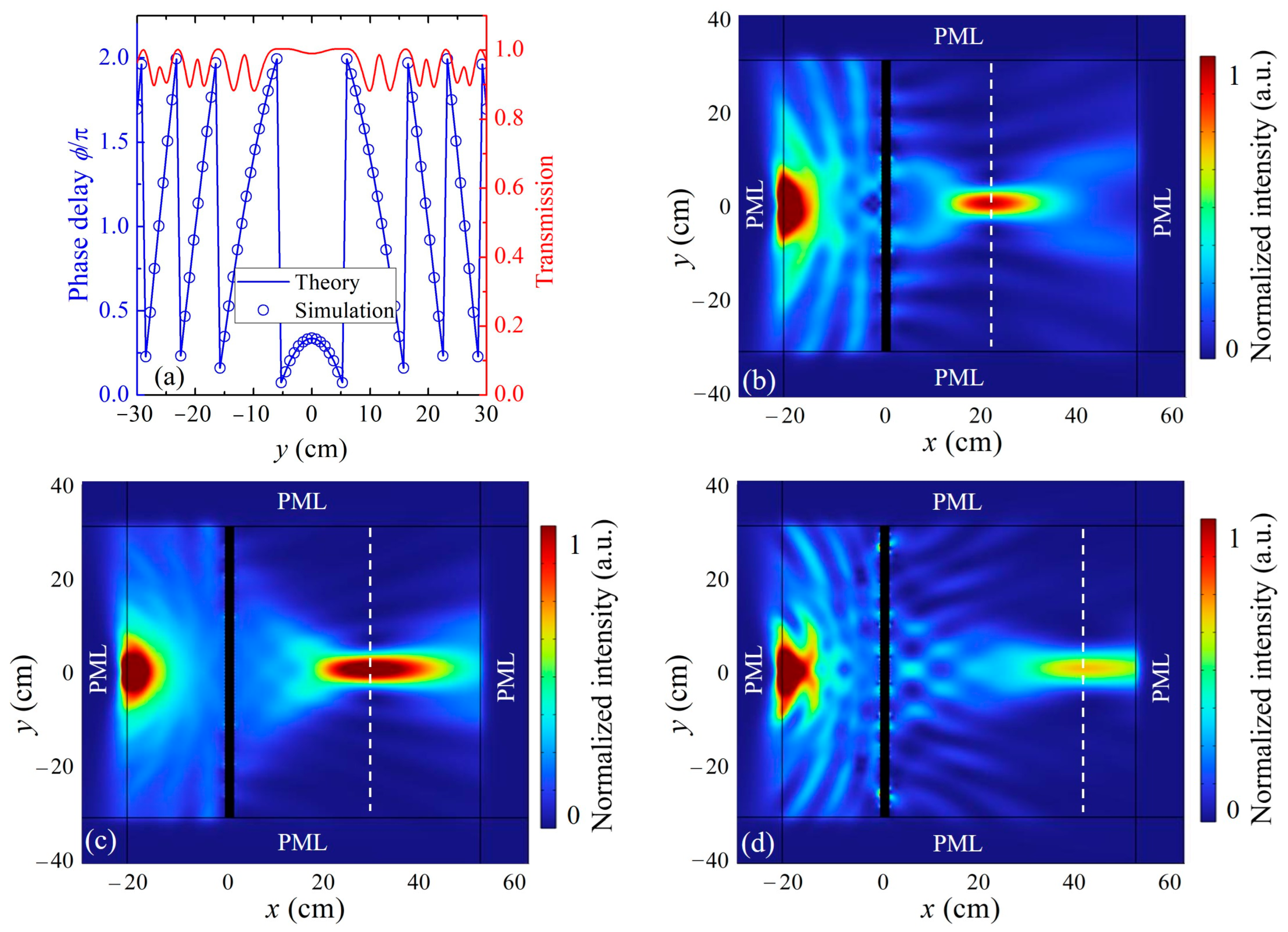
A second cylindrical-wave functionality—subwavelength focusing—was implemented by tailoring the transmission phase to converge spherical wavefronts at a specified focal distance of
L3 = 30 cm. The required phase delay is expressed as follows:
with
L2 = 20 cm denoting the source position.
As shown in
Figure 6a, the simulated phase delays (blue circles) closely follow the theoretical design (blue line), demonstrating the reliability of the phase implementation. The transmission coefficient (red curve) indicates that sufficient energy is transmitted through the structure to support efficient focusing. To evaluate broadband focusing behavior, full-wave simulations were conducted at 3600 Hz, 4000 Hz, and 4400 Hz. The corresponding intensity fields are presented in
Figure 6b,
Figure 6c, and
Figure 6d, respectively. In all three cases, the metasurface successfully compresses the diverging cylindrical wave into a focused region near the intended focal depth, denoted by the white dashed line. While minor variations in focal spot size and sidelobe patterns are observed due to frequency-dependent phase mismatch, each configuration exhibits a strong intensity peak, indicating robust focusing performance. These results confirm that the metasurface can effectively manipulate spherical-like wavefronts and maintain its functionality across a moderate frequency range, making it suitable for practical applications involving broadband or non-planar acoustic sources.
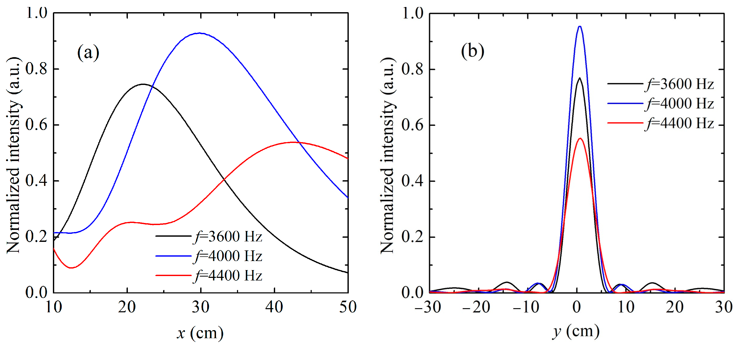
To quantitatively assess the focusing performance under varying frequencies, the normalized acoustic intensity distributions were extracted along the axial (
x) and transverse (
y) directions at the focal region, as shown in
Figure 7. In
Figure 7a, the axial intensity profiles reveal that the peak focal positions shift with frequency, as follows: at 4000 Hz, the intensity peak occurs near the target focal length of 30 cm, while at 3600 Hz and 4400 Hz, the focal spots are displaced forward and backward, respectively. These deviations reflect the frequency-dependent nature of the phase accumulation and its influence on wavefront convergence.
Figure 7b displays the corresponding lateral intensity distributions. At a design frequency of 4000 Hz, the transverse profile exhibits a sharp and narrow main lobe, indicating high spatial resolution and effective acoustic confinement. Although the 3600 Hz and 4400 Hz cases also produce focused spots, their broader main lobes and elevated side lobes suggest a slight reduction in lateral resolution and energy localization at off-design frequencies. These observations confirm that the proposed metasurface maintains strong cylindrical wave focusing performance across a moderate frequency band. The frequency-induced variations in focal position and sharpness remain limited, demonstrating the design’s robustness for applications requiring reliable near-field focusing from non-planar wave sources.
3.6. Manufacturing Feasibility and Tolerance Considerations
Although this work is based on numerical simulations, the proposed metasurface structure was intentionally designed with geometric simplicity and manufacturability in mind. The phase modulation relies solely on varying the tooth length of the unit cells, without requiring multi-material layering, active control elements, or complex embedded components. This passive and monolithic design makes it well-suited for fabrication using conventional techniques such as CNC milling, 3D printing, or laser cutting in rigid plastics or polymers.
To assess the practical robustness, we conducted a preliminary sensitivity evaluation of key geometric parameters, including the tooth length, f1, and width, w. The results indicate that small deviations (e.g., ±5% in f1) lead to only minor shifts in phase delay (typically <10°) and have minimal impact on transmission efficiency. This suggests that the structure is tolerant to reasonable manufacturing errors, which is crucial for real-world deployment. Furthermore, the design avoids deep subwavelength gaps or highly anisotropic channels that often complicate fabrication and alignment.
These characteristics support the feasibility of scaling the proposed design for experimental prototyping and integration into acoustic devices. Future work will focus on physically fabricating the metasurface and validating its broadband and multifunctional behavior under real-world conditions.
To further emphasize the performance and novelty of the proposed structure,
Table 2 compares our metasurface with representative transmissive designs reported in the last three years. Key metrics such as phase coverage, efficiency, functionality, and bandwidth are considered. The results highlight the unique combination of broadband performance, high transmission, and multifunctionality within a compact structure, setting this work apart from previously reported metasurfaces.
4. Conclusions
A grating-type labyrinthine acoustic metasurface has been developed to achieve full 0–2π phase modulation with high transmission efficiency, validated through numerical simulations. By adjusting the tooth length of the subwavelength unit cells, precise and tunable phase control is obtained. The metasurface successfully demonstrates the following five core wavefront manipulation functionalities: phase delay and transmission optimization, anomalous refraction, planar focusing, cylindrical-to-plane wave conversion, and cylindrical wave focusing. Each function is shown to operate stably over a 400 Hz bandwidth centered at 4000 Hz. The results confirm that the proposed metasurface can perform complex acoustic field transformations with high fidelity and minimal loss, even under off-design frequency conditions. This study highlights the metasurface’s potential for integration into advanced acoustic systems requiring compact, passive, and high-performance wavefront control, such as beamforming devices, acoustic imaging tools, and directional loudspeakers.
While this study provides a theoretical demonstration of the metasurface’s wavefront manipulation capabilities, several practical considerations remain to be addressed. First, the current analysis is purely numerical and does not account for viscous or thermal losses, which may influence performance in narrow acoustic channels. Second, although the metasurface structure was designed with fabrication in mind, implementing sub-millimeter features may still require high-resolution additive manufacturing or precision micromachining. Future work will focus on experimental prototyping, including the effects of manufacturing tolerances, material damping, and boundary layer losses, as well as extending the design to dynamic or reconfigurable systems. These efforts will help bridge the gap between numerical feasibility and real-world acoustic applications.


