Article

Anisotropic Fracture Energy of Boron-Doped P-Type Silicon by Microindentation: Influence of Temperature and Crystallographic Orientation

by
Wala eddine Guettouche
and
Ricardo J. Zednik
*
École de Technologie Supérieure, Université du Québec, Montréal, QC H3C1K3, Canada
*
Author to whom correspondence should be addressed.
Crystals 2025, 15(6), 533; https://doi.org/10.3390/cryst15060533
Submission received: 29 April 2025 / Revised: 24 May 2025 / Accepted: 29 May 2025 / Published: 2 June 2025

Abstract

:
This study investigates the anisotropic fracture behavior of boron-doped p-type single-crystal silicon on the (001) plane, under varying temperatures and crystallographic orientations, utilizing Vickers’ indentation experiments. Measurements performed at 25 °C, 50 °C, and 90 °C, reveal a strong dependence of mechanical properties—such as hardness, fracture toughness (K1c), and fracture energy—on both temperature and crystallographic orientation. At room temperature, the fracture energy peaks at 7.52 J/m2 along the [100] direction, with a minimum of 4.42 J/m2 along the [110] direction. As the temperature rises to 90 °C, the fracture energy decreases across all orientations, where values drop to 5.13 J/m2 and 3.65 J/m2 for the [100] and [110] directions, respectively. In contrast to pure, undoped silicon, the unexpected reduction in fracture energy with increasing temperature is likely due to dislocations pinned by the substitutional boron dopant at elevated temperatures, as well as the weakening of atomic bonds from thermal expansion. This valuable insight is critical for designing silicon-based devices, where understanding the fracture properties at elevated operating temperatures is important for ensuring reliability and performance.

1. Introduction

Silicon is widely used in various applications, including MEMS (Micro-Electro-Mechanical Systems) and solar cells, due to its electronic proprieties, along with its cost-effectiveness [1]. In brittle materials like silicon, failure typically occurs through the initiation and propagation of cracks. This type of fracture can lead to sudden and catastrophic failure in high-performance devices. This makes fracture toughness and energy, or the resistance to crack propagation, a critical factor in understanding fracture mechanics in these brittle materials [2].
Temperature is a critical factor impacting the mechanical performance of silicon. Thermal effects can generate internal stresses and modify fracture toughness [3,4]. This is particularly relevant since silicon-based semiconductor devices typically operate at around 70 °C for commercial applications and up to 90 °C for industrial use. Unfortunately, the mechanical properties and fracture behavior of Si are poorly understood at the elevated temperatures at which these devices typically operate. Since dislocation activation influences fracture toughness, some researchers have concentrated on investigating it at elevated temperatures [5,6,7]. Studies have shown that the brittle-to-ductile transition occurs at approximately 600 °C and is significantly affected by factors such as the material’s mechanical properties, crystal structure, and orientation [8,9]. In their on-chip tensile experiments, Nakao et al. [8] tested notched silicon films with a (100) surface orientation, where the tensile axis was aligned with the ⟨100⟩ direction. The fracture toughness was stable at 1.28 M P a m up to 60 °C, but after 70 °C, it increased considerably. Jaya et al. [7] performed a series of experiments on cantilevers of Si ⟨100⟩ micromachined by a focused ion beam (FIB). They observed a gradual increase in fracture toughness with temperature, showing a 23% increase at 150 °C compared with room temperature. In contrast, Lauener et al. [10] reported stable fracture toughness values from room temperature up to 150 °C using the pillar indentation splitting test. The discrepancies in these results can largely be attributed to the lack of a standardized method for determining fracture toughness. As Norton et al. [11] pointed out, the FIB-induced notch introduces residual stresses at the tip and can lead to an overestimation of toughness values.
Doping silicon with elements like boron to create p-type semiconductors is a common method for modulating its electrical properties [12]. However, studies have shown that doping can also alter the mechanical properties of silicon [13,14,15]. Despite this, few studies have specifically investigated the influence of doping on fracture behavior, limiting our understanding of fracture mechanisms in doped silicon under real-world conditions. Liu et al. [12]. demonstrated that boron doping enhances lattice trapping in the (111) [110] direction, thereby inhibiting crack propagation, while promoting fracture in the (110) [001] direction due to the weakening of Si–B bonds at the crack front.
Research on silicon fractures under real operating conditions is surprisingly limited, particularly regarding how doping, operation temperatures, and crystallographic orientation collectively influence failure mechanisms.
Vickers’ indentation (VI) remains one of the simplest and fastest methods for characterizing fracture energy [16]. This method is particularly useful for brittle materials with low fracture toughness [17]. The use of indentation crack size for toughness measurements was first introduced by Palmqvist [18]. Since then, various researchers have expanded on his approach, proposing alternative analytical solutions [19,20]. Among them are the Niihara and Anstis equations [17,21], which have become some of the most widely used, even for silicon [22,23,24]. However, the Niihara equation appears inappropriate for materials with low fracture toughness, such as single-crystal silicon, where reported K 1 c values for the {100} crack plane at room temperature range from 0.75 to 1.29 M P a m [25]. The Niihara equation is generally more suitable for materials with a significantly higher fracture toughness, such as WC-Co, which exhibits values greater than 10 M P a m [25]. Furthermore, there is disagreement regarding the appropriate choice of the constraint factor [26]. On the other hand, the Anstis equation was proposed as a better fit for silicon as Anstis used silicon to calibrate the toughness equations and accounted for the residual stress intensity term in his formulation. Unfortunately, the anisotropy characteristic of single-crystal silicon is neglected in these formulations, and in most indentation fracture studies, single-crystal silicon is often treated as though it were isotropic [25].
The present paper aims to quantify the fracture energy in p-doped single-crystal silicon using an indentation technique, and thereby explore the effect of crystallographic orientation and temperature, up to the typical operational temperature of 90 °C.

2. Materials and Methods

The experiments were conducted on boron-doped p-type silicon wafers on the (001) plane. These wafers had a resistivity of 10–20 Ohm-cm, corresponding to a uniform doping concentration of 1015 atoms/cm3 of boron, and a thickness of 525 µm ± 20 µm. The wafers were mirror polished on one side. Indentations were made using an automated Clemex microhardness tester equipped with a Vickers indenter. Indentations were performed at three different temperatures: 25 °C ± 1 °C, 50 °C ± 1 °C, and 90 °C ± 1 °C. A PTC (positive temperature coefficient) heating plate with a PID (Proportional–Integral–Derivative) controller was integrated into the Clemex system to maintain precise temperature control during indentation.
The silicon sample was placed on the heating plate, which was directly mounted on a rotating test stage. This assembly was positioned on an XY moving test stage, as shown in Figure 1. The rotating stage enabled alignment of the desired crystallographic orientation with the indenter axis. Angular alignment was verified using a digital goniometer with a precision of ±1°. The XY moving stage allowed accurate control of indent positioning, ensuring that each indent was spaced at least ten times the maximum expected crack length to prevent crack interaction and misleading results. The positioning was pre-programmed using the Clemex software. A load of 100 gf was applied for angles ranging from 0° to 15° relative to the ⟨110⟩ direction and the indenter diagonal, while a reduced load of 50 gf was used for angles up to 45° to minimize chipping and ensure reliable outcomes. The two different loads were necessitated due to the great anisotropy inherent in silicon, such that one indentation load was insufficient to probe all orientations. Between 10 and 15 indentations were made for each direction.
After air cooling to room temperature, crack lengths were measured using a Keyence VHX-7000 digital microscope (Osaka, Japan). Crack lengths (c) were measured from the center of the impression to the crack tip. In principle, changes in temperature can affect crack lengths due to thermal stresses; we, therefore, ensured that cooling was gradual (no forced cooling) and indeed did not observe any increase in cracking during cooling back to room temperature. If exactly four radial cracks were observed—one at each corner of the indent—all were measured. If more than four cracks formed, only the four most symmetric and longest radial cracks were considered. In the case of chipping or significant spallation, the indentation was not used in our measurements. The average was calculated from all valid cracks and used to determine the fracture toughness using a modified version of the Anstis equation (Equation (1)), where the homogeneous Young’s modulus ( E ) in the original equation was replaced with the directional Young’s modulus ( E h k l u v w ) to account for silicon’s anisotropy:
K 1 c = 0.016 E h k l u v w H 1 2 ( P / c 3 / 2 )
where H is the hardness, P is the Vickers applied load, and c is the radial crack length. In this study, variations in the directional Young’s modulus due to temperature changes were not considered, nor was the effect of p-type doping on the elastic properties of the material.
The directional Young’s modulus E h k l u v w , in each direction u v w for any crystallographic plane h k l , can be calculated using the following equation [27]:
1 E h k l u v w = S 11 2     S 11 S 12 0.5 S 66 m 2 n 2 + n 2 p 2 + m 2 p 2
where m , n , and p are the direction cosines which describe the angles between the chosen direction u v w and the principal crystallographic axes 100 , 010 , and 001 , respectively. S i j are the constants in elastic compliance matrix, for silicon the values of S 11 , S 12 , and S 44 are 0.767 × 10 11   P a 1 , 0.213 × 10 11   P a 1 , 1.256 × 10 11   P a 1 , respectively [28].
In this work, the critical energy release rate (ERR), or fracture energy, was determined by assuming that the crack extension remained relatively straight, and that propagation ceased when the maximum crack length was reached. The fracture energy was calculated using the modified Irwin relation, based on data from the Vickers indentation tests. This relation allows for the consideration of crystallographic effects on the energy release rate of single crystal silicon. In plane strain condition, the fracture energy (ERR) is given by [27,29,30]:
G 1 c h k l u v w = π K 1 c 2 1 v h k l α β 2 ξ h k l u v w
where ξ h k l u v w is the equivalent direction-dependent anisotropic Young’s modulus, and v h k l α β is the anisotropic Poisson’s ratio between two orthogonal crystallographic directions α and β within any crystallography plane h k l , and can calculated by [31]:
v h k l α β   = s 12 + S 11 S 12 0.5 S 66 m α 2 m β 2 + n α 2 n β 2 + p α 2 p β 2 s 11 2 S 11 S 12 0.5 S 66 m a 2 n a 2 + n a 2 p a 2 + m a 2 p a 2
where ( m α , n α , p α ) are the direction cosines of direction α and ( m β , n β , p β ) are the direction cosines of direction β .
Integrating Equation (1) into Equation (3) we obtain:
G 1 c h k l u v w = π 0.016 E h k l u v w / H 1 2 P / c 3 / 2 2 1 v h k l α β 2 ξ h k l u v w
Equation (5) represents the fracture energy, or critical energy release rate (ERR), for mode 1 under plane strain conditions, now modified to incorporate the influence of material elastic anisotropy and crack orientation on the ERR.
From an atomic perspective, fracture in brittle materials results from the breaking of atomic bonds [32]. Single-crystal silicon, with its periodic structure and strong covalent bonds, allows for the estimation of fracture energy using a bond energy approach under the assumption that no surface reconstruction, environmental reactions, or plastic deformation occurs [33,34,35,36].
The fracture energy for a specific crystallographic plane h k l can be estimated by multiplying the bond energy by the number of bonds broken per unit area on the corresponding fracture plane. Since fracture energy can be defined as twice the surface energy γ h k l , this approach leads to the following expression for fracture energy:
2 γ h k l = E b S I a 0 2 4 max h , k , l h 2 + k 2 + l 2
where the lattice constant of silicon is a 0 = 0.543   n m , and the bond energy of silicon at room temperature is E b S I = 226   k J / m o l [37].

3. Results

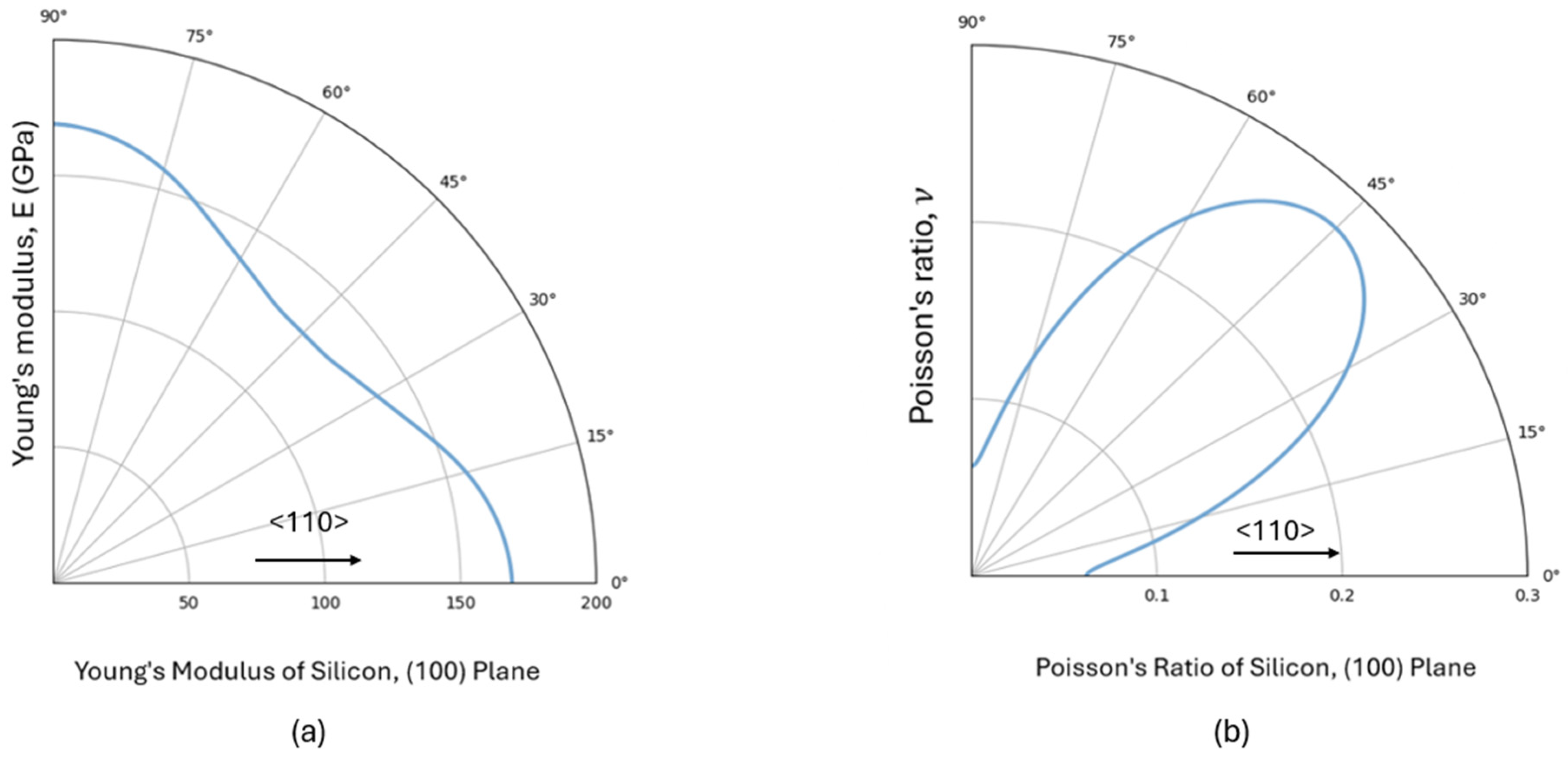
Figure 2 presents the variation in Young’s modulus and Poisson’s ratio for silicon within the (100) crystallographic plane, obtained from Equations (2) and (4), respectively. The angles are measured from the ⟨110⟩ direction. Young’s modulus reaches its maximum value of 169 GPa along the ⟨110⟩ direction, while its minimum value of 130 GPa is observed along the ⟨100⟩ direction. Conversely, Poisson’s ratio exhibits a maximum of 0.28 along the ⟨100⟩ direction and a minimum of 0.06 along the ⟨110⟩ direction.
Figure 3 provides representative micrographic images of the Vickers indentations, while the overall average results are summarized in Table 1. Each reported value corresponds to the average of 10–15 indentation measurements. These results show a clear dependence on both temperature and orientation, with maximum values consistently observed in the ⟨100⟩ crystallographic orientation and minimum values in the ⟨110⟩ direction.
At 25 °C, the hardness showed a gradual increase with the orientation angle, ranging from a low value of 11.05 GPa to a peak value of 13.06 GPa. Fracture toughness ( K 1 c ) exhibited a 36% increase with the increase in angle, rising from 0.81 M P a m to 1.10 M P a m , while fracture energy also showed a 1.7-fold increase, from 4.42 J/m2 to 7.52 J/m2.
At 50 °C, the hardness values decrease relative to those at room temperature, ranging from 10.55 GPa at angle 0° to 12.59 GPa at 45°—this angle is between the [110] crystallographic direction and the diagonal of the indenter. Both the fracture toughness and the fracture energy slightly decrease compared with 25 °C but increase with angle up to 45°, indicating that elevated temperatures reduce these mechanical properties.
At 90 °C, there is a further decrease in the hardness observed. A similar trend was observed for the fracture toughness, reaching 0.90 M P a m at 45°. In the case of fracture energy, an 18% decrease is observed compared with the 25 °C value in the ⟨110⟩ direction, and a 38% decrease in the ⟨100⟩ direction, with corresponding measurements of 3.65 J/m2 and 5.13 J/m2, respectively.
The theoretical fracture energy for pure, undoped silicon was computed using Equation (6), based on literature values and the corresponding Young’s modulus values at 25 °C shown in Figure 1; values for elevated temperatures are not readily available in the literature. The fracture energy for undoped silicon exhibits a similar trend, rising from 3.60 J/m2 along the ⟨110⟩ crystallographic directions to 5.09 J/m2 along the ⟨100⟩ directions. Similar values for boron-doped silicon were not readily available in the literature.
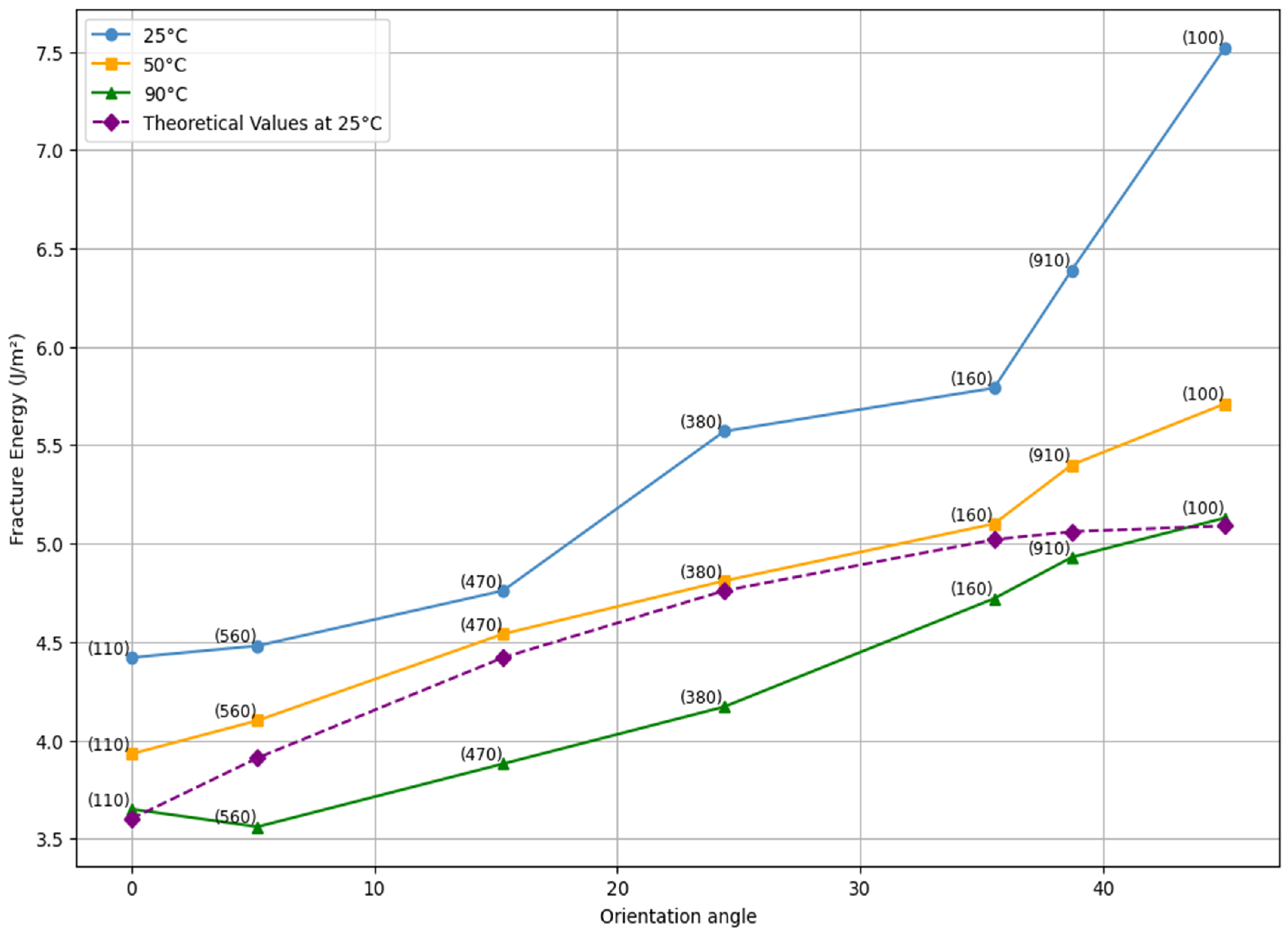
Figure 4 shows the fracture energy of boron-doped single-crystal silicon measured at three different temperatures (25 °C, 50 °C, and 90 °C) as a function of indent orientation angle, represented on the horizontal axis. Additionally, theoretical values at room temperature (for undoped Si) are plotted in the same graph for direct comparison. The straight tie lines were included to help guide the eye but do not have a direct physical interpretation.

4. Discussion

The results clearly highlight the anisotropy of fracture energy in single-crystal silicon, showing that fracture energy increases as we move from the (110) plane to the (100) plane. This anisotropic behavior is evident across all tested temperatures, with the (110) plane consistently showing the lowest fracture energy, while the (100) plane exhibits the highest. This suggests that the (100) plane is the most resistant to crack propagation, whereas the (110) plane is the least resistant. Comparing the experimental results with theoretical predictions at room temperature, we observe that the experimental values are generally greater; this divergence can be attributed to the fact that the theoretical model does not account for plastic work and that minor secondary cracks or spallation were not considered. In contrast, the experimental values, derived from the Vickers indentation fracture data and calculated using the modified Anstis equation, consider the residual stresses caused by plasticity. Additionally, the theoretical curve appears to flatten beyond an angle of 35°, indicating that, theoretically, the fracture energy remains almost constant between 35° and 45°. However, the experimental results show an increase beyond 35°, particularly at room temperature. This indicates that for these planes, there is a greater contribution of plasticity compared with other planes, as shown by the observed distortions beneath the indenter imprint, as illustrated in Figure 3.
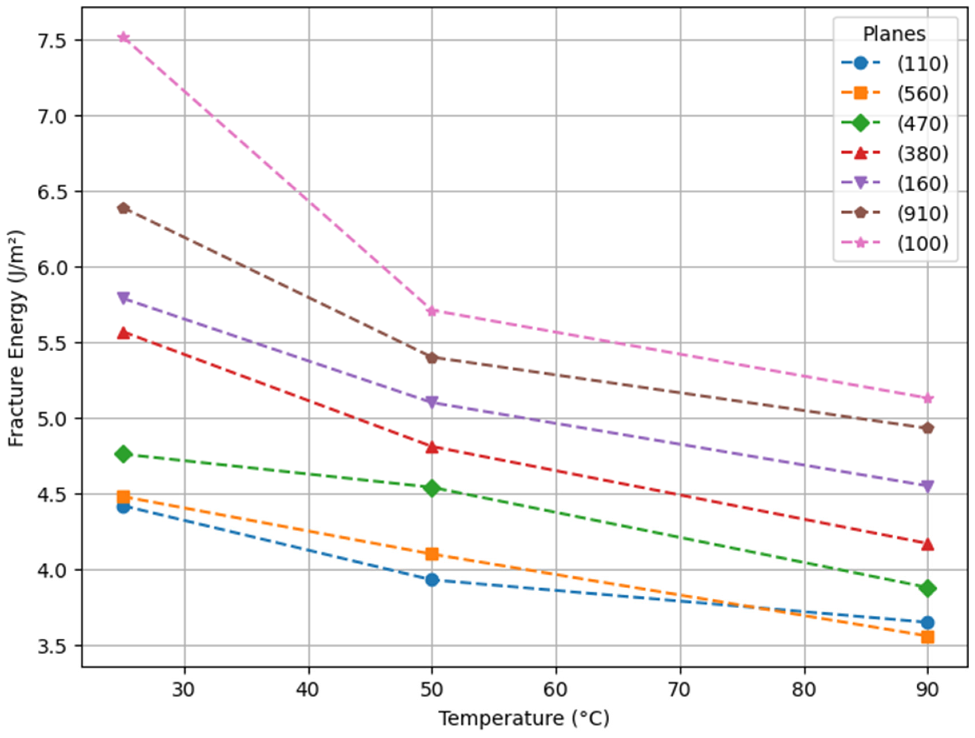
Surprisingly, the experimental data show a significant decrease in the fracture energy of boron-doped p-type single-crystal silicon as temperature rises, as illustrated in Figure 5. This behavior contrasts with previous studies on undoped silicon [7,8,10], where an increase in fracture toughness was observed due to dislocation activation, typically occurring at 60 °C to 70 °C around the fracture tip; these mobile dislocations absorb energy before fracture occurs. In the present study, it appears that the boron dopant has a significant effect on the mechanical properties; this effect on the mechanical properties cannot be ignored when designing semiconductor devices.
In the case of boron-doped silicon, the observed reduction in fracture energy with increasing temperature in this study aligns with previous research on p-doped silicon [4]. This suggests that dislocation mobility may be restricted at this temperature range, likely due to the presence of boron atoms that pin dislocation motion. Additionally, thermal expansion effects further contribute to the observed reduction in fracture energy, as the elevated temperatures stretch and weaken atomic bonds. The contrasting effect of temperature on fracture energy for doped and undoped silicon highlights the need for careful consideration in silicon device design. Additionally, further study is necessary to confirm the underlying mechanism explaining this observation, and to explore the effects of alternate dopants, including other acceptors like indium (In) and aluminum (Al), as well as donors such as arsenic (As), antimony (Sb), or phosphorous (P).

5. Conclusions

Fracture mechanisms in pure, undoped single-crystal silicon have been extensively studied at room temperature, but the fracture behavior of doped silicon at the elevated temperatures typically experienced in operation remains poorly understood; indeed, the effect of doping on the mechanical properties is largely ignored. In this study, the fracture energy of (100) boron-doped silicon wafers (p-type) over a temperature range from room temperature to 90 °C was investigated for different crystallographic orientations using an indentation method.
The Vickers microindentation experiments highlight the anisotropic nature of silicon, with the [100] orientation consistently showing the highest fracture energy across various temperatures, while the [110] orientation displays the lowest, leading to preferential crack growth in this direction. Temperature significantly influences the mechanical properties of boron-doped silicon. As the temperature rises from 25 °C to 90 °C, hardness, fracture toughness, and fracture energy decrease, indicating a reduction in the material’s resistance to crack propagation. This study reveals unexpected trends in the fracture behavior of boron-doped silicon at operational temperatures, which contrast with prior studies on undoped silicon, where increased fracture energy at elevated temperatures was observed due to dislocation activation.
Controlling fracture behavior is critical to ensuring the long-term reliability of electronic devices. Although the mechanical behavior of undoped silicon at room temperature is well understood, this unexpected finding for boron-doped silicon shows that further investigation is warranted. This is particularly important since almost all silicon-based electronic devices use doped silicon operating above room temperature. Further investigation is therefore necessary to fully explain the observed fracture behavior of doped silicon at the elevated temperatures experienced during typical device operation.

Author Contributions

W.e.G.: Writing—original draft, Methodology, and Investigation. R.J.Z.: Writing—review and editing, Validation, Supervision, and Funding acquisition. All authors have read and agreed to the published version of the manuscript.

Funding

The authors acknowledge with appreciation the funding provided by the Natural Sciences and Engineering Research Council of Canada (NSERC) Discovery Grant RGPIN-2022-05125.

Data Availability Statement

The data and experimental results used in this study will be made available by any reasonable request to the corresponding author.

Acknowledgments

The authors gratefully acknowledge Philippe Bocher for allowing them to use the Clemex Vickers Indentation system and Yasser Zedan for his technical assistance.

Conflicts of Interest

The authors declare no conflicts of interest.

References

  1. Lee, S. (Ed.) Advanced Material and Device Applications with Germanium; InTech: London, UK, 2018. [Google Scholar] [CrossRef]
  2. Zhang, Z.; Wang, X.; Meng, F.; Liu, D.; Huang, S.; Cui, J.; Wang, J.; Wen, W. Origin and evolution of a crack in silicon induced by a single grain grinding. J. Manuf. Process. 2022, 75, 617–626. [Google Scholar] [CrossRef]
  3. Masolin, A.; Bouchard, P.-O.; Martini, R.; Bernacki, M. Thermo-mechanical and fracture properties in single-crystal silicon. J. Mater. Sci. 2013, 48, 979–988. [Google Scholar] [CrossRef]
  4. Hintsala, E.D.; Bhowmick, S.; Yueyue, X.; Ballarini, R.; Asif, S.A.S.; Gerberich, W.W. Temperature dependent fracture initiation in microscale silicon. Scr. Mater. 2017, 130, 78–82. [Google Scholar] [CrossRef]
  5. Armstrong, D.E.J.; Tarleton, E. Bend Testing of Silicon Microcantilevers from 21 °C to 770 °C. JOM 2015, 67, 2914–2920. [Google Scholar] [CrossRef]
  6. Korte, S.; Barnard, J.S.; Stearn, R.J.; Clegg, W.J. Deformation of silicon—Insights from microcompression testing at 25–500 °C. Int. J. Plast. 2011, 27, 1853–1866. [Google Scholar] [CrossRef]
  7. Jaya, B.N.; Wheeler, J.M.; Wehrs, J.; Best, J.P.; Soler, R.; Michler, J.; Kirchlechner, C.; Dehm, G. Microscale Fracture Behavior of Single Crystal Silicon Beams at Elevated Temperatures. Nano Lett. 2016, 16, 7597–7603. [Google Scholar] [CrossRef]
  8. Nakao, S.; Ando, T.; Shikida, M.; Sato, K. Effect of temperature on fracture toughness in a single-crystal-silicon film and transition in its fracture mode. J. Micromech. Microeng. 2008, 18, 015026. [Google Scholar] [CrossRef]
  9. Li, X.; Fan, Z.; Huang, S.; Lu, M.; Huang, H. Brittle-to-ductile transition in nanoscratching of silicon and gallium arsenide using Berkovich and Conical tips. Appl. Surf. Sci. 2023, 637, 157934. [Google Scholar] [CrossRef]
  10. Lauener, C.M.; Petho, L.; Chen, M.; Xiao, Y.; Michler, J.; Wheeler, J.M. Fracture of Silicon: Influence of rate, positioning accuracy, FIB machining, and elevated temperatures on toughness measured by pillar indentation splitting. Mater. Des. 2018, 142, 340–349. [Google Scholar] [CrossRef]
  11. Norton, A.D.; Falco, S.; Young, N.; Severs, J.; Todd, R.I. Microcantilever investigation of fracture toughness and subcritical crack growth on the scale of the microstructure in Al2O3. J. Eur. Ceram. Soc. 2015, 35, 4521–4533. [Google Scholar] [CrossRef]
  12. Liu, B.; Zhang, Y.A.; Li, Y.J.; Wang, X.F.; Yue, Y.J. Cleavage anisotropy of boron doped cracks in crystalline silicon. Microelectron. Reliab. 2022, 138, 114653. [Google Scholar] [CrossRef]
  13. Guolin Yu, G.Y.; Junji Watanabe, J.W.; Katsutoshi Izumi, K.I.; Kenshiro Nakashima, K.N.; Takashi Jimbo, T.J.; Masayoshi Umeno, M.U. Mechanical Property Characterization of Boron-Doped Silicon by Berkovich-Type Indenter. Jpn. J. Appl. Phys. 2001, 40, L183. [Google Scholar] [CrossRef]
  14. Sakakima, H.; Izumi, S. Carrier-doping effect on strength and deformations in group-IV crystals. Int. J. Mech. Sci. 2025, 293, 110169. [Google Scholar] [CrossRef]
  15. Hirakata, H.; Homma, S.; Noda, H.; Sakaguchi, S.; Shimada, T. Effects of excess electrons/holes on fracture toughness of single-crystal Si. J. Appl. Phys. 2023, 133, 035101. [Google Scholar] [CrossRef]
  16. Moulins, A.; Andrusyszyn, F.; Dugnani, R.; Zednik, R.J. Indentation fracture toughness of semiconducting gallium arsenide at elevated temperatures. Eng. Fail. Anal. 2022, 137, 106417. [Google Scholar] [CrossRef]
  17. Niihara, K.; Morena, R.; Hasselman, D.P.H. Evaluation ofK Ic of brittle solids by the indentation method with low crack-to-indent ratios. J. Mater. Sci. Lett. 1982, 1, 13–16. [Google Scholar] [CrossRef]
  18. Palmqvist, S. A method to determine the toughness of brittle materials, especially hard metals. Jernkontorets Ann. 1957, 141, 300–306. [Google Scholar]
  19. Moradkhani, A.; Panahizadeh, V.; Hoseinpour, M. Indentation fracture resistance of brittle materials using irregular cracks: A review. Heliyon 2023, 9, e19361. [Google Scholar] [CrossRef]
  20. Ponton, C.B.; Rawlings, R.D. Vickers indentation fracture toughness test Part 2 Application and critical evaluation of standardised indentation toughness equations. Mater. Sci. Technol. 1989, 5, 961–976. [Google Scholar] [CrossRef]
  21. Anstis, G.R.; Chantikul, P.; Lawn, B.R.; Marshall, D.B. A Critical Evaluation of Indentation Techniques for Measuring Fracture Toughness: I, Direct Crack Measurements. J. Am. Ceram. Soc. 1981, 64, 533–538. [Google Scholar] [CrossRef]
  22. Lemaitre, P. Fracture toughness of germanium determined with the Vickers indentation technique. J. Mater. Sci. Lett. 1988, 7, 895–896. [Google Scholar] [CrossRef]
  23. Tanaka, M.; Higashida, K.; Nakashima, H.; Takagi, H.; Fujiwara, M. Fracture Toughness Evaluated by Indentation Methods and Its Relation to Surface Energy in Silicon Single Crystals. Mater. Trans. 2003, 44, 681–684. [Google Scholar] [CrossRef]
  24. Ebrahimi, F.; Kalwani, L. Fracture anisotropy in silicon single crystal. Mater. Sci. Eng. A 1999, 268, 116–126. [Google Scholar] [CrossRef]
  25. Rickhey, F.; Marimuthu, K.P.; Lee, K.; Lee, H. Indentation cracking of monocrystalline silicon considering fracture anisotropy. Theor. Appl. Fract. Mech. 2019, 100, 128–138. [Google Scholar] [CrossRef]
  26. Moulins, A.; Dugnani, R.; Zednik, R.J. Anisotropic fracture energy and toughness of single crystal gallium arsenide by microindentation. Eng. Fract. Mech. 2023, 292, 109631. [Google Scholar] [CrossRef]
  27. Wachtman, J.B., Jr. Determination of Elastic Constants Required for Application of Fracture Mechanics to Ceramics. In Concepts, Flaws and Fractography, 2nd ed.; Fracture Mechanics of Ceramics; Springer: Boston, MA, USA, 1973; pp. 49–68. [Google Scholar]
  28. McSkimin, H.J.; Bond, W.L.; Buehler, E.; Teal, G.K. Measurement of the Elastic Constants of Silicon Single Crystals and Their Thermal Coefficients. Phys. Rev. 1951, 83, 1080. [Google Scholar] [CrossRef]
  29. Sih, G.C.; Paris, P.C.; Irwin, G.R. On cracks in rectilinearly anisotropic bodies. Int. J. Fract. Mech. 1965, 1, 189–203. [Google Scholar] [CrossRef]
  30. Flügge, S. Elasticity and Plasticity/Elastizität und Plastizität; Springer: Berlin/Heidelberg, Germany, 1958; pp. 551–590. [Google Scholar] [CrossRef]
  31. Brantley, W.A. Calculated elastic constants for stress problems associated with semiconductor devices. J. Appl. Phys. 1973, 44, 534–535. [Google Scholar] [CrossRef]
  32. Tanaka, M.; Higashida, K.; Nakashima, H.; Takagi, H.; Fujiwara, M. Orientation dependence of fracture toughness measured by indentation methods and its relation to surface energy in single crystal silicon. Int. J. Fract. 2006, 139, 383–394. [Google Scholar] [CrossRef]
  33. Wolff, G.A.; Broder, J.D. Microcleavage, bonding character and surface structure in materials with tetrahedral coordination. Acta Crystallogr. 1959, 12, 313–323. [Google Scholar] [CrossRef]
  34. DelRio, F.W.; Cook, R.F.; Boyce, B.L. Fracture strength of micro- and nano-scale silicon components. Appl. Phys. Rev. 2015, 2, 021303. [Google Scholar] [CrossRef]
  35. Pérez, R.; Gumbsch, P. Directional Anisotropy in the Cleavage Fracture of Silicon. Phys. Rev. Lett. 2000, 84, 5347–5350. [Google Scholar] [CrossRef]
  36. King, S.W.; Antonelli, G.A. Simple bond energy approach for non-destructive measurements of the fracture toughness of brittle materials. Thin Solid Films 2007, 515, 7232–7241. [Google Scholar] [CrossRef]
  37. Nejati, M.; Bahrami, B.; Ayatollahi, M.R.; Driesner, T. On the anisotropy of shear fracture toughness in rocks. Theor. Appl. Fract. Mech. 2021, 113, 102946. [Google Scholar] [CrossRef]
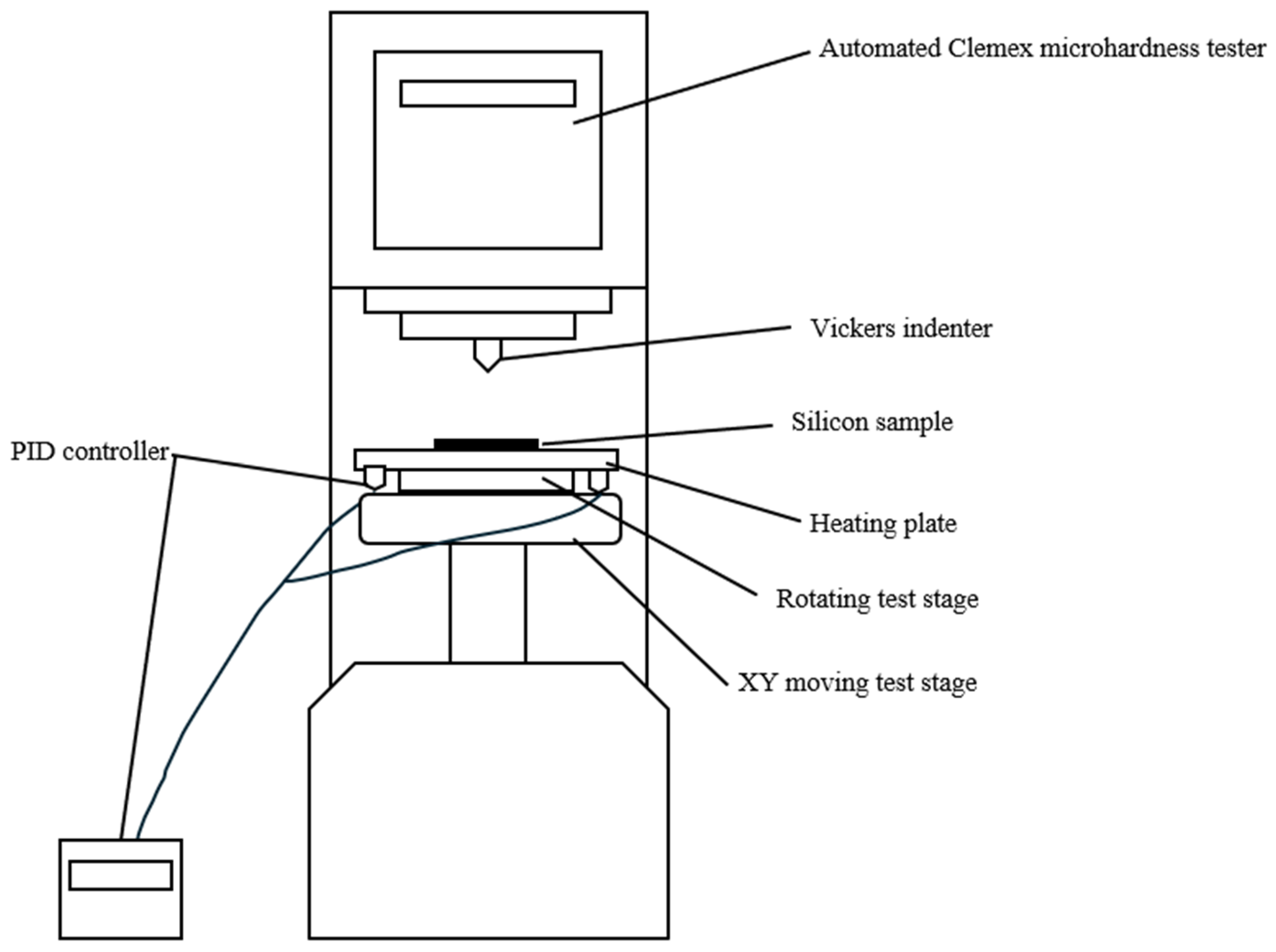
Figure 1. Schematic diagram of the indentation setup.
Crystals 15 00533 g001
Figure 2. Elastic constants of silicon in the (100) plane as a function of crystallographic orientation: (a) Young’s modulus and (b) Poisson’s ratio.
Crystals 15 00533 g002
Figure 3. Micrographs of Vickers indentations on single-crystal silicon at different temperatures (25 °C, 50 °C, and 90 °C) and orientations. The angle is between the <110> direction and the indenter diagonal. (ac): Indentations at θ = 0° and temperatures of 25 °C, 50 °C, and 90 °C, respectively. (df): Indentations at θ = 45° and temperatures of 25 °C, 50 °C, and 90 °C, respectively.
Crystals 15 00533 g003
Figure 4. Orientation-dependent fracture energy of single-crystal silicon at various temperatures: the angle (in degrees) is measured between the <110> crystallographic direction and the indenter diagonal.
Crystals 15 00533 g004
Figure 5. Fracture energy variation with temperature for different crystallographic planes in boron-doped single-crystal silicon.
Crystals 15 00533 g005
Table 1. Measured fracture toughness and fracture energy of boron-doped silicon for various indent orientation angles at 25 °C, 50 °C, and 90 °C.
H V G P a K 1 C   ( M P a m ) G 1 c (J/m2)
Angle (±1°)Plane25 °C50 °C90 °C25 °C50 °C90 °C25 °C50 °C90 °C
(110)11.0510.5510.160.810.770.744.423.933.65
(560)11.3111.039.840.820.780.734.484.103.56
15°(470)11.7411.1310.330.850.830.774.764.543.88
25°(380)12.0011.5210.850.930.860.805.574.814.17
35°(160)12.4211.9711.110.960.900.875.795.104.72
40°(910)12.7512.3011.541.010.930.896.395.404.93
45°(100)13.0612.5911.801.100.970.907.525.715.13
Disclaimer/Publisher’s Note: The statements, opinions and data contained in all publications are solely those of the individual author(s) and contributor(s) and not of MDPI and/or the editor(s). MDPI and/or the editor(s) disclaim responsibility for any injury to people or property resulting from any ideas, methods, instructions or products referred to in the content.