Article

Impact of ZrO2 and Si3N4 Ceramics Dispersion on the Ti6Al4V Matrix: Mechanical and Microstructural Characteristics Using SPS

by
Anthony O. Ogunmefun
1,*,
Emmanuel R. Sadiku
1,
Linda M. Teffo
1 and
Williams K. Kupolati
2
1
Department of Chemical Engineering, Tshwane University of Technology, Pretoria 0183, South Africa
2
Department of Civil Engineering, Tshwane University of Technology, Pretoria 0183, South Africa
*
Author to whom correspondence should be addressed.
Crystals 2025, 15(6), 531; https://doi.org/10.3390/cryst15060531
Submission received: 14 April 2025 / Revised: 20 May 2025 / Accepted: 29 May 2025 / Published: 2 June 2025

Abstract

This study investigates the effect of duo-ceramic zirconia and silicon nitride (ZrO2-Si3N4) particles and their reinforcement proficiencies on a Ti6Al4V alloy, consolidated using the spark plasma sintering (SPS) technique. The selected sintering parameters are, viz., 900 °C temperature, 50 MPa pressure, 10 min of holding time, and 100 °C/min of sintering rate. SEM/EDS and XRD equipment were used to disclose the microstructural evolution and phase identification of created composites. The mechanical characteristics of the resulting composites were determined using the nanoindentation technique. All consolidated sintered composites showed excellent densification, with sample relative densities reaching 96.65%. Significant improvements were also made in their nanomechanical characteristics; among the composite samples with different volume fractions, the ceramics with the lowest volume percentage had the best mechanical characteristics, whereas the sintered samples with the highest ceramic volume percentage showed a decrease in mechanical proficiencies and relative density. Composite S1, with the lowest volume fraction of the duo-ceramic particles, was seen to have a significant mechanical property improvement better than other composites, S2 and S3, in terms of measured Vickers microhardness, elastic modulus, and nano hardness values at a sintering temperature of 900 °C. Consequentially, composite specimens S2 and S3’s mechanical characteristics and relative densities dropped as the volume fractions of the duo-ceramic particles increased.

1. Introduction

Following the developments in producing efficient materials to address issues in manufacturing and other engineering-related sectors, researchers and engineers have embraced novel fabrication methods to surmount several challenges related to advanced material design and manufacturing for various applications. The limits of monolithic materials have been enhanced in recent years by introducing ceramic matrix composites. Several researchers in recent times have extensively strengthened titanium alloys (Ti-alloy) and their matrices with ceramics [1,2,3]. These second-phase particles have great potential for reinforcement because of their exceptional fracture toughness, high hardness, high elastic modulus, and high thermal stability [4]. They are also excellent for highly structural and wear-resistant applications [5,6]. Commonly used ceramic reinforcements are titanium carbide, titanium nitride, zirconia, dinickel boride, silicon carbide, etc.
Among several types of titanium alloy, Ti6Al4V alloy is exceptional, consequent upon its extraordinary mechanical qualities at room temperature, as well as strong corrosion resistance and ease of welding. Ti-alloy is prone to several engineering uses, which makes it find extensive application in the manufacturing of structural elements [7,8]. Due to these remarkable properties, titanium-based materials are highly sought after for use in automotive, nuclear, marine, and aerospace applications, among other fields [9]. Even with their exceptional qualities, titanium alloys are not widely used because of their high cost, low hardness, poor wear characteristics, low surface hardness, and high coefficient of friction [7,10]. As a result, numerous boosting techniques have been employed to improve their inherent characteristics. Because of its poor tribological behavior, Ti6Al4V alloy is not appropriate for applications requiring a combination of high strength and good wear characteristics [11]. Collaboratively, several material scientists have strengthened titanium alloys using ceramic particles and second-phase metallic nitrides to enhance the bulk properties of composites based on titanium.
Of all the ceramic additives that are acceptable for strengthening titanium alloys, zirconia (ZrO2) and silicon nitride (Si3N4) particles rank among the best. Zirconia is a popular oxide that stabilizes zirconium dioxide, a ceramic material that is stabilized at room temperature by adding yttrium oxide, a process known as yttria-stabilized zirconia. It is a very resilient and robust ceramic substance that is both biocompatible and inert. Phase transformation toughening is a reinforcing mechanism resulting from the tetragonal-monoclinic transformation, and it is responsible for these features [12]. A rise in volume coincides with this change, producing compressive stress and strengthening the ceramic material’s resistance to cracking [13]. Research has demonstrated that bulk zirconia passive layers put on substrates are appropriate for use as heat-resistant turbine blades [14] and corrosion inhibitors [15]. The ‘stabilized’ phase of zirconia is frequently more advantageous.
Heat causes zirconia to go through abrupt phase transitions. These phase transitions can be avoided by adding tiny amounts of yttria, and the resultant material has improved mechanical, electrical, and thermal qualities. The tetragonal phase may occasionally be metastable. A load applied at a crack tip can magnify the stress concentration and cause the tetragonal phase to change to monoclinic, with the accompanying volume expansion, if enough of the metastable tetragonal phase is present. This phase shift can increase the fracture toughness by compressing the crack and delaying its propagation. Zirconia is used as a thermal barrier coating, or TBC, in jet and diesel engines to enable operation at greater temperatures because of its extremely low heat conductivity [16].
Like most ceramics, the conventional Si3N4 ceramic has a low fracture toughness, which leads to a low Weibull modulus, poor reliability, and limited damage tolerance. A literature analysis indicates that the fracture toughness of hot-pressed Si3N4 ranges from 3 to 5 MPam1/2 [8,17,18,19], which is insufficient for the envisaged applications. Nonetheless, it has been discovered that the fracture toughness of ceramics or metal matrices based on titanium is increased by the addition of particulate zirconia (ZrO2) as reinforcement [8,20]. It is one of the few ceramic monoliths that is resistant to extreme heat gradients and thermal stress [21]. Si3N4 is a good ceramic for high-temperature structural applications, such as thermocouple tubes and steam turbine engines, because of its special properties [22]. High flexural modulus, outstanding creep resistance, and high hardness features are only a few of Si3N4’s many exceptional qualities as an advanced structural ceramic [23]. Additionally, several researchers have used the spark plasma sintering process to strengthen titanium alloys with ceramic particle additions, and their findings have had an impact on the mechanical characteristics and wear of titanium alloys, including TiN [24], TiB2 [25], ZrB2 [26], Al2O3, SiC, TiN, B4C, TiC, TiB2 [27], carbon nanotubes [28], and graphene nanoplatelets [29].
The combination of these bio-ceramic features suggests the major objectives for the ternary consolidation of these powders using the pulsed electric current sintering techniques, basically for the conception of aerospace, automotive, nuclear, and military applications. Incorporating zirconia’s exceptional strength, fracture toughness, and hardness with silicon nitride’s thermal shock resistance, wear resistance, and chemical inertness properties into the titanium matrix is the exact purpose of this study for service enhancement in aerospace and biomedical industries, especially at elevated temperatures. Notably, the resulting composites’ mechanical and microstructural characteristics are largely determined by the chemical interaction between the reinforcing ceramic particles and the titanium alloy matrix. The following elements form the basis of this interaction: (i) chemical compatibility between the matrix’s constituent elements and the reinforcement particles; (ii) internal stability between impurities induced during processing and the inherent stability of the constituent elements; and (iii) environmental stability, which depends on how the constituent elements and the processing environment interact [30].
This study discusses the possibility of producing near-net-shaped composites with superior mechanical properties from titanium alloys and two distinguished ceramics, ZrO2 and Si3N4, utilizing powder metallurgy technology. According to Tohgo et al. [31], ZrO2 ceramic impacts the microstructural and mechanical characteristics of titanium alloy. It was reported that the sintered alloys showed a 93% relative density upon addition. Ti2ZrO and Ti2O, two new and advantageous intermetallic phases, were formed, according to X-ray diffraction (XRD) investigation. Spark plasma sintered titanium alloy reinforced with zirconia and nickel was created and examined by Obadele et al. [32]. ZrO2 reinforcement had an impact on the hardness and microstructure, acting as a pinning force in the neck region as a dispersoid. According to reports, this pinning effect prevents grain development and dislocation movement inside the grain border. By uniformly dispersing the nanoceramics TiN/TiCN in its matrix, Falodun et al. [33,34] reported success in manipulating the particles in the Ti6Al4V microstructure along the grain boundary. The relative density dropped slightly from 98.6% to 97.05% when 0.5–1.0 vol.% of TiCN was introduced at 1000 °C; this was explained by the formation of pores and grain growth with the matrix. Similar research employing SPS to consolidate the duo of nitrides and Si3N4 ceramics in the Ti6Al4V matrix was also conducted by Abe et al. [35] and Kgoete et al. [36], and their outcomes agree. The inclusive objective of this study is to utilize sintering techniques to consolidate the Ti6Al4V alloy with Si3N4 and ZrO2 ceramic particles at a 900 °C temperature. This study also intends to unravel the sintered composites’ microstructural progression and their mechanical features.

2. Materials and Methods

The as-received powders, viz., Ti6Al4V (APS 88 μm), ZrO2 (APS 44 μm), and Si3N4 (0.8 μm), all powders with a purity level of over 99%, were provided by Alfa Aesar. The ceramic powders were blended with Ti6Al4V alloy composite according to the different volume fractions, viz., S1 (w = 5 vol. % ZrO2; x = 5 vol.% Si3N4), S2 (w = 15 vol. % ZrO2; x = 5 vol.% Si3N4), and S3 (w = 10 vol. % ZrO2; x = 5 vol.% Si3N4). Table 1 tabulates the vol.% configuration of the dual-ceramic compositions of ZrO2 and Si3N4 ceramic particles. The ternary powders were all dispensed in a tubular mixer and subjected to translational and rotational movements for 8 h at a relative speed of 50 rpm to produce a homogeneous blend. The sintering heating rate of 100 °C/min was employed for 10 min at a pressure of 50 MPa in a vacuumed environment with a temperature of 900 °C. Figure 1 depicts the morphological characterization of the as-received raw material powders.
The SEM micrograph in Figure 1a reveals the non-porous spherical particles of the Ti6Al4V alloy [37]; Figure 1b shows a round (with a hollow doughnut-like) morphology with many satellites of ZrO2; and Figure 1c reveals the hexagonal prism particles of Si3N4 [38]. During blending, steel balls with a diameter of about 8 mm were added to the powder vessel at a ball-to-powder weight ratio of 2:5 to improve the dispersion of the ZrO2 and Si3N4 reinforcement into the matrix [39]. The HHPD 25, a hybrid spark plasma sintering furnace produced by FCT Germany, was employed. The furnace chamber was run in a vacuum, with the powder compacts retained under 50 MPa of external pressure and subjected to a 10 min sintering dwell time. The furnace was then heated to 900 °C at a 100 °C/min heating rate. Composite disk-shaped samples were sintered, measuring approximately 5 mm in height and 30 mm in diameter. Before undergoing additional investigation, the resulting compacts were sandblasted to eliminate graphite contamination.

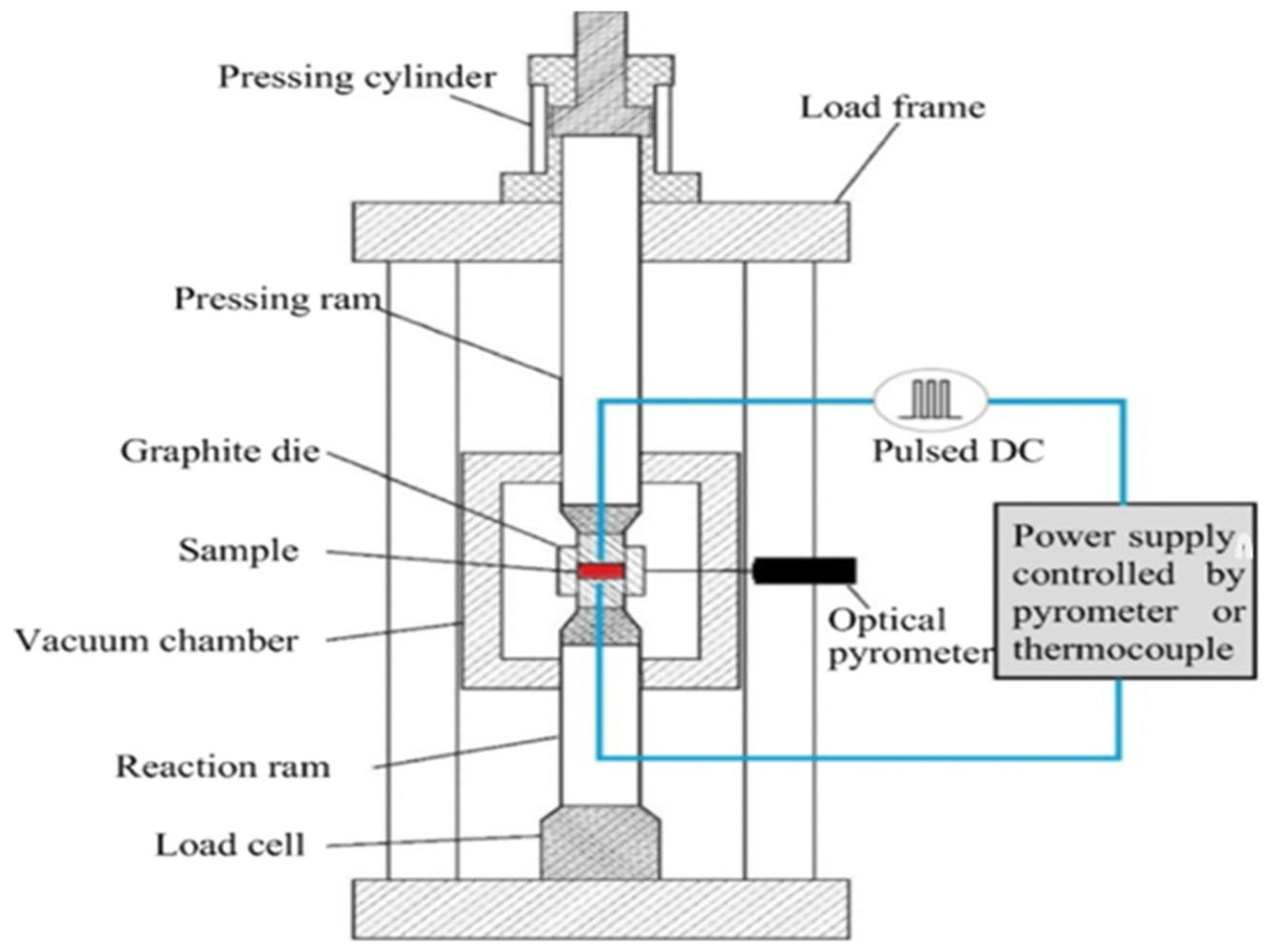
2.1. Algorithms of Execution of Spark Plasma Sintering

To promote densification, a pulsed DC is passed through the powder, localized heating is produced by plasma discharge, and pressure is applied concurrently. Fast and effective sintering at comparatively low temperatures is made possible by the combination of targeted heating and pressure. Below is the detailed breakdown of the execution algorithm:
  • Prepare Powder: Selection and preparation of titanium and bioceramic composite powders.
  • Load Powder in Die: Place powder inside the graphite die for sintering.
  • Apply Pulsed DC Current: High-frequency pulsed electrical current is introduced.
  • Heat via Joule Heating and Pressure: Current induces heat, and uniaxial pressure assists in densification.
  • Grain Boundary Diffusion and Densification: Particles fuse due to diffusion processes.
  • Hold at Sintering Temperature: Maintains temperature for optimal consolidation.
  • Controlled Cooling: Ensures material stability and microstructure refinement.
  • Remove from Die: Extracts the sintered composite from the mold.
  • Characterization and Quality Control: Mechanical and microstructural evaluation of the final product.
The schematic diagram of the spark plasma sintering operations is shown in Figure 2, illustrating the execution process, as stated herein.

2.2. Metallography, Characterization, and Densification Studies

In preparation for the microstructural examination, the consolidated Ti6Al4V-Si3N4-ZrO2 compacts, the sintered composites, were sandblasted and then ground using SiC papers, starting with P120 grits and working up to P2000 grits. Ground surfaces were then polished and etched using Kroll solution. The microstructural and phase constitution of the composites was subsequently ascertained by characterizing the samples. The PANalytical X-ray diffractometer hardware used monochromatic Cu target Kα radiation at 40 kV and 40 mA to perform the X-ray diffraction experiments, while the X’Pert HighScore plus 3.0 software analyzed the resulting data, which are the constituent phases inherent in the sintered composites. The microstructure of the polished surfaces of the sintered composites, as well as the elemental composition assessment, was examined using scanning electron microscopy equipped with electron dispersive spectroscopy, SEM (JEOL JSM 7900 F, JEOL, Akishima, Japan) model.

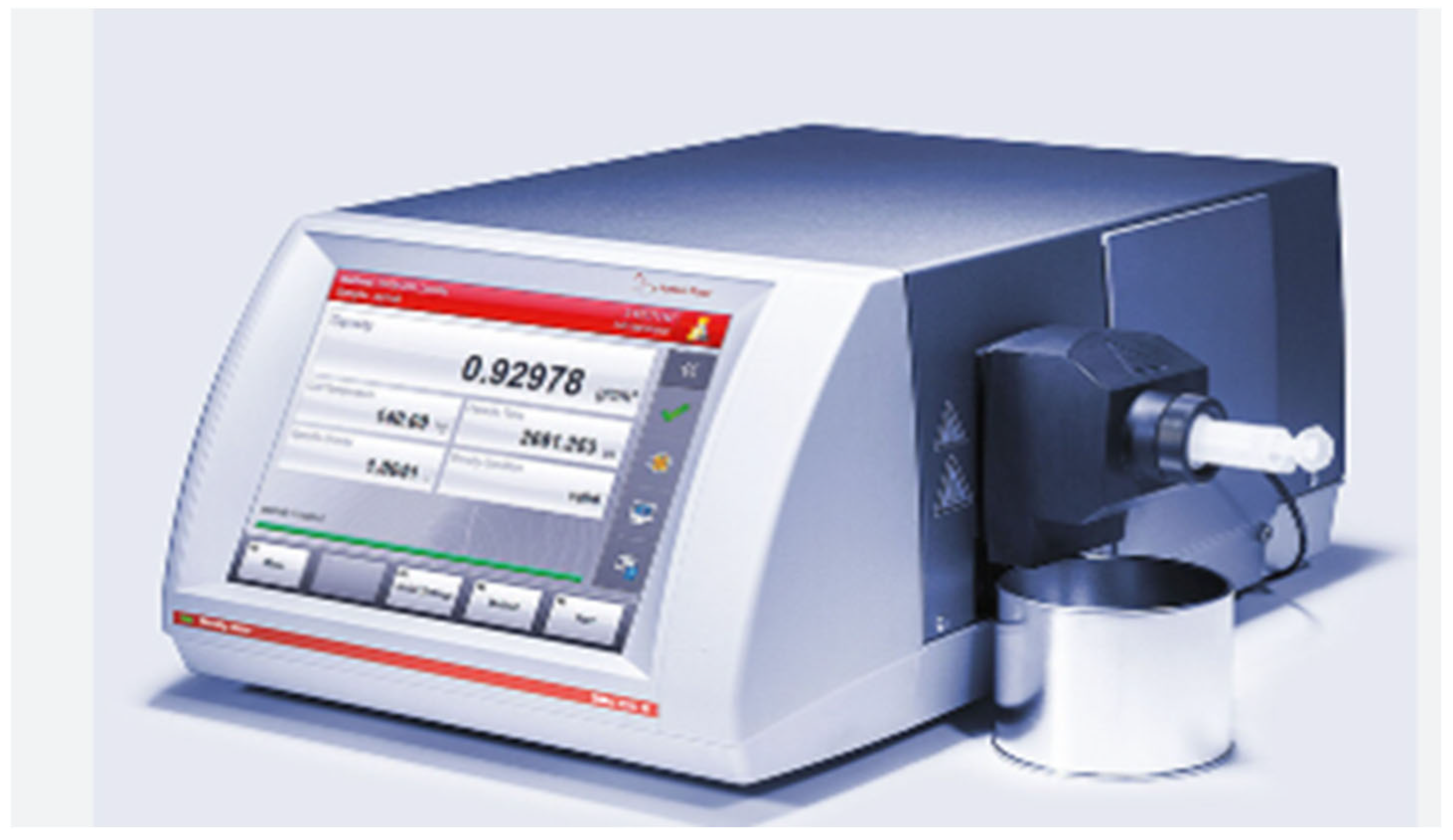
2.3. The Procedure for the Measurement of Relative Density Through Archimedes’ Principle

The densities of sintered compacts were determined using Archimedes’ principle in both air and deionized water. The densitometer automatically determined the bulk density of each compact. The recorded density of each composite was then calculated using an average of five measurements conducted on each specimen. The relative densities of the specimens of the findings obtained were used to enumerate how the duo ceramic particles (Si3N4-ZrO2) affected the matrix composites of Ti6Al4V alloy, and this was calculated using the” Rules of Mixture”, using the theoretical densities of the composites to divide the bulk density values measured using the Archimedes technique.
The step-by-step procedures of utilizing Archimedes’ principle to determine the relative density of the sintered composites are summarized herewith, viz.,
Step 1: Weighing each sintered compact in air.
To determine the weight of the compact while it is hung in the air, a spring balance is used. The samples’ weight measurements will be noted as Wair 1, Wair 2, and Wair 3.
Step 2: Weighing each compact in water.
Make sure the spring balance is not submerged when you carefully submerge these compacts in a container of water. For each of the three samples, the apparent weight of the compacts in water will also be noted as WH2O 1, WH2O 2, and WH2O 3.
Step 3: Determine the buoyant force.
The weight differential between the compact in air and water is known as the buoyant force (FB): Wair − WH2O. (This shall apply to the three samples.)
Step 4: Determine the relative density.
The ratio of the buoyant force to the weight of an equivalent volume of water is the compacts’ relative density (RD). Since the volume of water displaced is equal to the volume of the object, you can use the density of water (ρw) and the object’s volume (V) to calculate the weight of an equal volume of water (ρw ∗ V ∗ g).
Then, the relative density of the compact samples of the study is calculated:
RD = (Wair − WH2O)/(ρw ∗ V ∗ g)
Another way to describe the relative density is as follows:
Relative Density = Wair/(Wair − WH2O), since the weight of an object in air (Wair) is equal to the weight of an equal volume of water.
Step 5: (Alternative) Determine how dense the composite material is.
The density can be computed using the following formula:
Density, ρ = mass/volume
where mass is obtained from the object’s weight in air (mass = Wair/g), having determined the volume of the study’s compact samples. Table 1 reveals the respective determined relative densities of each composite, having applied the steps mentioned above, and the porosity, calculated from the relationship equation, as stated herewith.
Porosity (%) = 100 − Relative Density (%).
The image of the apparatus used for determining the relative density, the densitometer, is shown in Figure 3.

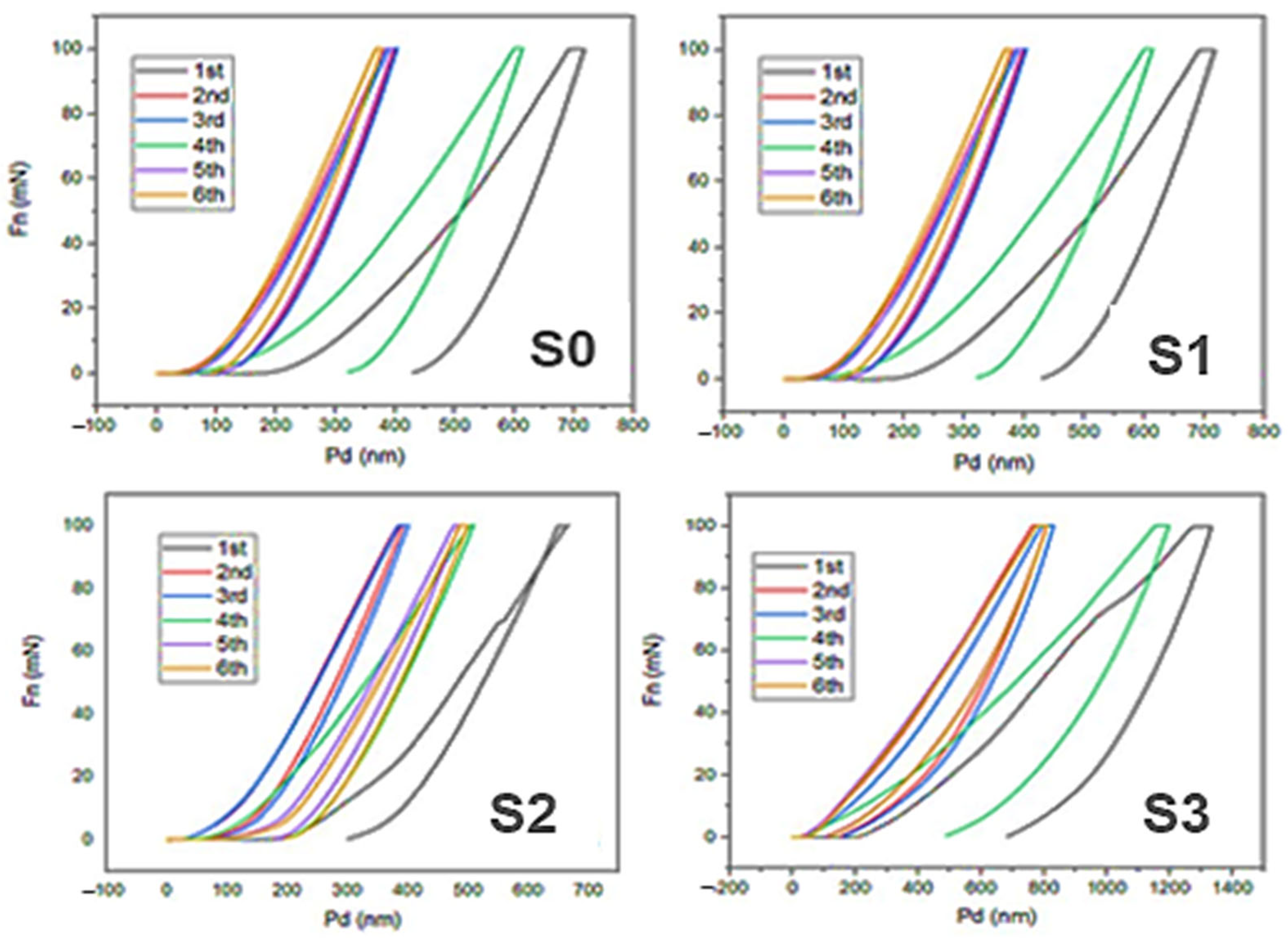
2.4. Nanoindentation Properties of Ti64-W% ZrO2-X% Si3N4 Composites

Using a Berkovich diamond indenter and an Anton Paar Hit 300 nanoindentation tester, ASTM E2546 was used to examine the nanoindentation properties of the sintered composites. The nanomechanical quantities, including the yield pressure, elastic strain, plasticity index, elastic recovery index, elastic modulus, and nano hardness, may be determined using the nanoindentation data. The load–displacement curve was used to calculate these properties using the Oliver and Pharr method [40]. The microhardness, nano hardness, and elastic modulus will be measured for this investigation.

3. Results and Discussion

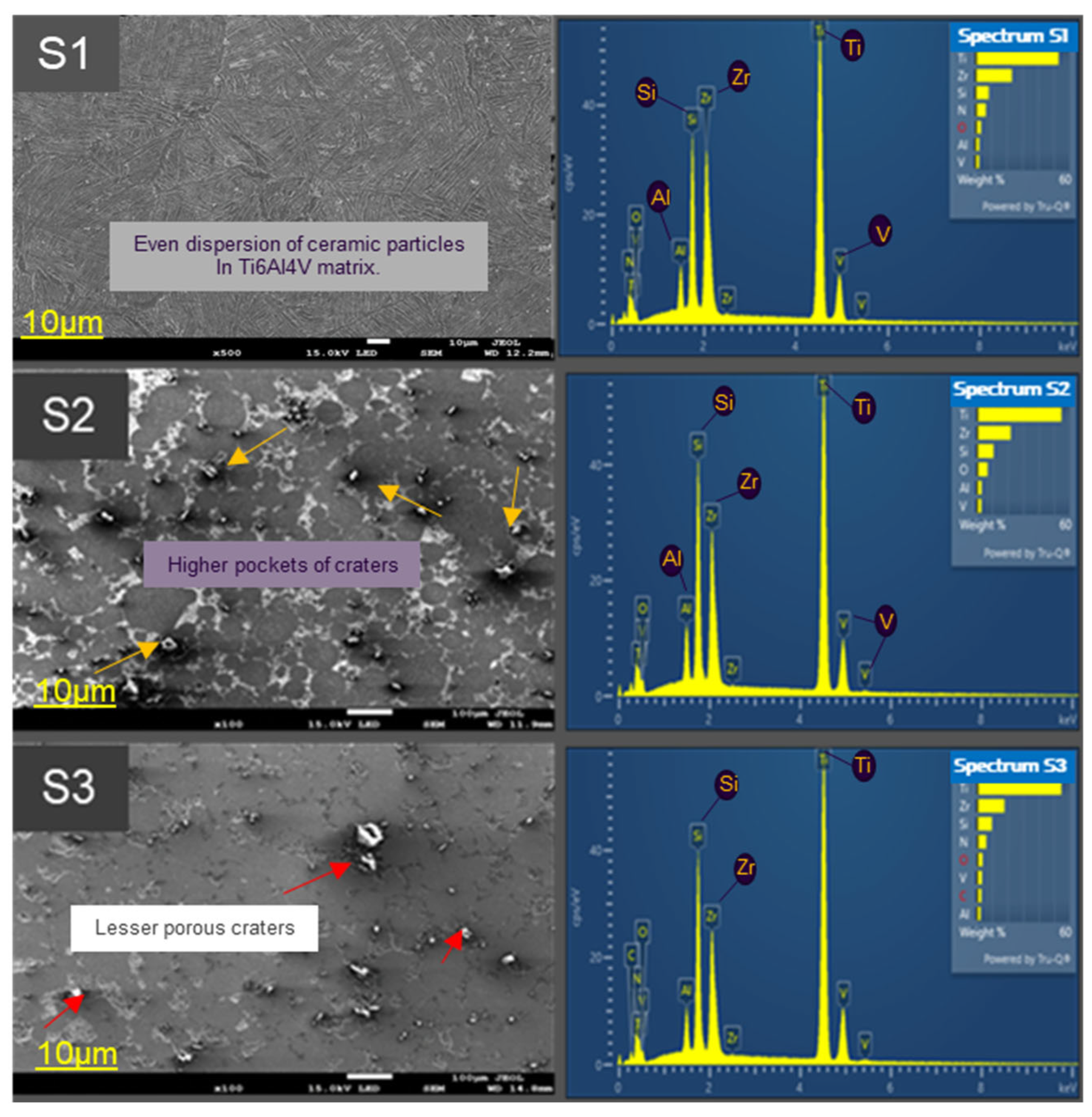
3.1. Properties of the Consolidated Composites’ Microstructure
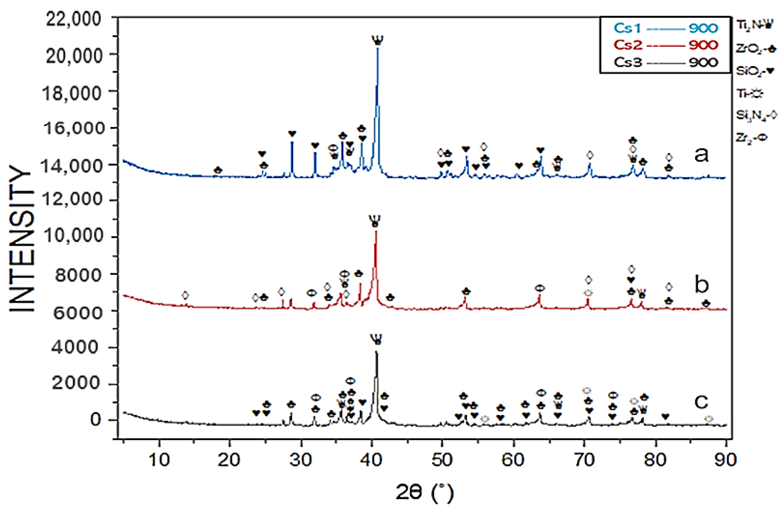
In Figure 4, a typical microstructure of Ti6Al4V alloy, considered in this experiment as the control sample, is shown, revealing two different phases that include both the α-Ti and β-Ti phases. According to the EDS peaks, the presence of Al and V, respectively, is thought to be responsible for the stability of these dual-phase alloys. One explanation for the alloy’s relatively low nanomechanical value (Table 1) is the dominance of α-Ti lamellar, which gives it toughness and creep resistance, and the lack of evidence of previous β-Ti grain boundaries, which give it high strength and fatigue resistance, in the (α + β) Ti-rich matrix, as shown in Figure 4 [41,42]. The backscattered EDS layers reveal the component phases in the alloy.
Figure 5 displays the SEM/EDS micrographs that reveal the morphologies and intensity peaks of the samples: specimen S1 (Ti6Al4V + 5 vol.% ZrO2 + 5 vol. % Si3N4); specimen S2 (Ti6Al4V + 15 vol.% ZrO2 + 5 vol. % Si3N4); and specimen S3 (Ti6Al4V + 10 vol.% ZrO2 + 5 vol. % Si3N4) at a 900 °C sintering temperature, 50 MPa of pressure, a sintering rate of 100 °C/min, and a dwelling time of 10 min.
The backscattered electron (BSE) micrographs distinctly describe the microstructural evolution of the trio-specimens. The primary and secondary phases of the corresponding composites of this study are depicted with black, gray, and white regions, as seen from the microstructures. According to Pennycook et al. [43], an electron beam’s interaction with a material results in a visual contrast that is determined by the variations in atomic numbers of the constituent elements. The microstructures of all samples exhibit a greyish hue, which indicates the presence of the Ti6Al4V phase; the dark areas represent the silicon phase, while the brilliant (whitish) sections suggest lighter atoms of the zirconia phase. Generally, the ZrO2 phase is observed in the matrix phase, while the Si3N4 phase agglomeration has a few porosity patches seen throughout the entire microstructure.
Figure 5 depicts the SEM-EDS micrograph profiles for the specimens. In S1, the duo-ceramic particles are seen to be uniformly dispersed throughout the alloy matrix, with sparing porous areas in the microstructure. The titanium matrix in (S2) contains more ceramic additives evenly distributed, but, as seen, more porous craters, trapped volatiles, or air bubbles are visible, and that may have occurred during the sintering process [30]. A higher volume fraction of the duo-ceramic additives in the composite specimen at 900 °C sintering temperature could also be a result of the higher porous sites [31]. Micrograph S2 shows the dominance of the zirconia phase in the microstructure, which suggests a partial nucleation caused by the supersaturation of the admixture particles. S3 causes fewer craters than S2, and reinforcements are uniformly distributed throughout the matrix, as can be observed from the microstructure.
Hypothetically, the volume percentage of ceramics in the S3 composite is lower than in S2, where a porous area is predominantly less in the sample. This may also be explained by the same factors mentioned for S2. The experimental observation in this study confirms that the Ti6Al4V alloy and its composites with different volume fractions of the duo-ceramic particles (ZrO2/Si3N4) were successfully consolidated using the spark plasma sintering procedure.

3.2. XRD Analysis

Figure 6 displays the X-ray diffractograms of sintered ternary composites, Ti6Al4V-w% ZrO2-x% Si3N4 consolidated at 900 °C. It is found from the micrographs that none of the diffractograms of case samples 1 (a), 2 (b), and 3 (c) displayed any noticeable peak extension. This suggests that no reaction occurred at the beginning of the sintering process, which could result from internal strain in the powders brought on by the incredibly tiny grain size of the initial powder [44,45]. The diffraction peaks of the elemental and interfacial phases become visible as the reinforcements are incorporated into the titanium alloy matrix. It is found that the phases primarily intersect with a characteristic peak intensity, confirming a distinct phase history of composites. These in situ phases are anticipated to act as a dislodgment obstruction at the grain boundaries of the matrix–ceramics interfaces, strengthening the composites and improving their mechanical properties [46]. When comparing the samples at S2 and S3 to S1, which had an even composition of both primary and secondary phases as revealed on their diffraction peaks, a closer examination of the XRD peaks of these results shows that while their diffraction peaks are similar, the phases’ compositions appear to be slightly different, which may be related to slight differences in their mechanical proficiency and relative densities [47].
This suggests that there may have been some interfacial bonding events between the powders of the primary elemental powders, Ti6Al4V, ZrO2, and Si3N4, during the sintering process. The Ti and Zr phases are seen to overlap at 2θ = 78.610; Ti, Ti2N, and ZrO2 are observed at the peak intensity of 2θ = 78.619; the X-ray diffractogram, S1 in Figure 6a, shows the phases of Ti2N, Ti, and ZrO2 aligning perfectly at 2θ = 36.318; the Ti phase is at the highest peak intensity when 2θ is equal to 42.071 and 50.861. Figure 6b’s X-ray diffractogram of S2 shows that the ZrO2, Ti2N, and Zr phases are at the 2θ peak intensity of 31.605, correspondingly; the Ti phases emerged at their respective peak intensities of 38.497 and 51.133; the SiO2 interfacial phase overlaps the Ti phase at 2θ = 79.477; and at 2θ = 74.006. More of the primary phases and the in situ reactions of SiO2 and Ti2N were observed overlapping at the same peak intensity. The ZrO2 phase predominates in the microstructure of the composites, as shown by the diffractogram of S3 in Figure 6c, which shows peak intensities of 2θ at 24.877, 31.87, 33.09, 36.818, and 63.39. At 2θ = 40.170, the Ti and Ti2N phases overlap. At 2θ = 71.610, the primary phases of Si3N4, Ti, and Zr also overlap. Interestingly, at 2θ = 75.19, the in situ interfacial phases of Ti2N and SiO2 overlap with Si3N4, which enhances the relative of the formed composites. The thermochemical process of the main and secondary phases, which leads to the emergence of the Ti2N and SiO2 phases as a densifier and subsequent densification of the composites, is summarized in the diffractograms. At their respective temperatures, the phases of Al and V were not discernible, which could have been because of the low percentage composition of the complete phases that rendered them.

3.3. Relative Density and Porosity Calculations for Ternary Composites Sintered at 900 °C

The experimentally measured relative density and porosity are shown in Figure 7 together with their numerical values and response bar chart. The determination of the relative densities of the composites was achieved by dividing the bulk/experimental with the theoretical densities and finding their percentages.
The porosity of the sintered composites was determined by proxy. Research has indicated that porosity is usually brought about by a small amount of agglomeration or clustering at the matrix-reinforcing particle interface [48]. From the data of Figure 7, the composites of samples S1, S2, and S3 attained practically full densification. Sample S1 attained a densification value of 98.94%, while sample S3 came next at 97.74%. Composite sample S2 experiences a close match with sample S3 at 97.10% to be the least densified composite. The graph in Figure 7 also reveals an increase in the porosity of the three different samples, proportionate with an increase in the reinforcement volume fraction of each sample from S1 to S3. Unarguably, the least reinforced composite, S3, proves to be better in nanomechanical value than the control samples, S0, unreinforced Ti6Al4V alloy, at 96.65% densification. These results reflect a significant improvement in the densification of the trio-composite samples with the duo-second-phase ceramic particles.

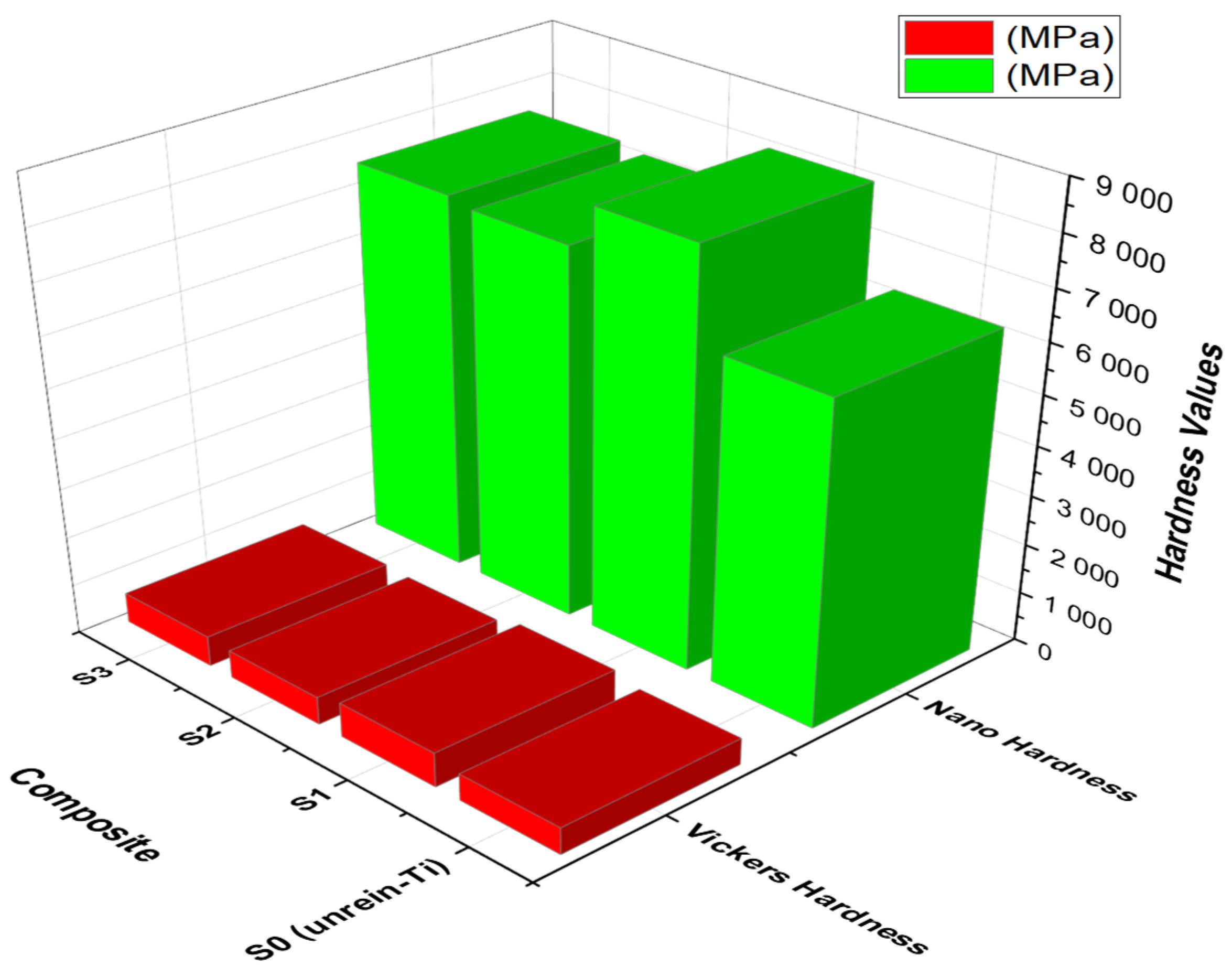
3.4. Sintered Composites’ Nanomechanical Quantities

Table 2 reveals the sintered composite samples’ elastic modulus, nano hardness, and Vickers microhardness values. Also, Figure 8 graphically illustrates the nano hardness and Vickers hardness relationships of the sintered composites, and the two quantities show a similar response in their hardness indices. This explicitly confirms the direct relationship between the variable parameters of this study, viz., the additive volume fraction and sintering temperature effects on the matrix alloy, and their nanomechanical proficiency. From the reading, S1 records the highest values of all these nanomechanical properties, followed by specimen composite S3, while S2 composites recorded the least nanomechanical values from the study. A comparatively high ceramic-additive volume fraction can be suspected as responsible for this drop in mechanical properties [49,50] in sample S2, especially at the set sintering temperature of 900 °C. The percentage densification of composites, as recorded, also may be responsible for the potentially improved hardness, as reported also by Wang et al. [51].
As observed from the tabulated readings, composite S1 with the lowest volume fraction of reinforcement recorded the highest elastic modulus (175.65 GPa), followed by S3 (153.02 GPa) and S2 (156.16 GPa). This is evidence that S1 has a greater resistance to non-permanent (elastic) deformation under stress, meaning that it is stiffer and requires more force to deform, making it the best of the formed composites [52]. Several factors can be responsible for a drastic decline in the elastic modulus of composites in this study: One possible explanation for this could be inadequate interfacial bonding between the matrix-reinforcement particles [41]. The mechanical characteristics are strengthened due to a decrease in crystallite size, an increase in lattice strain caused by the inclusion of second-phase ceramic additives, and the development of an in situ exothermic reaction during the sintering process, as indicated by the higher elastic modulus than the sintered composite material showed in S1 [52].

3.5. Nanoindentation Analysis of Mechanical Properties of the Sintered Composites

The nanoindentation load–depth profile for the unreinforced titanium alloy, S0 and sintered Ti6Al4V-w% ZrO2-x% Si3N4 samples S1, S2, and S3, viz., w = 5, 15, and 10; and x = 5, 5, and 5, composites at 100 mN load are presented in Figure 9. The hardness values of the phases in the trio samples were measured using the nano-indentation method. From the penetration profile, each result presents the average values of six indentations per sample. In reality, the hardness–penetration depth diagrams clearly show three separate zones: the increasing, decreasing, and linear sections. Generally, due to the formation of dislocation loops, the hardness value increases in the first zone with penetration depths below 100 nm as the penetration depth is increased. The hardness then decreases as the penetration depth increases in S2, within the second zone, where it ranges from 100 to 300 nm. As revealed in Figure 9, the samples’ curves show no signs of pop-in effects and are smooth. The unreinforced titanium sample, S0, was seen to have experienced the highest penetration, and this can be attributed to its non-reinforcement of the alloy’s matrix. Its loading, maximum heights, and unloading curves seem to be the same as S1. The indenter on these two samples seems to have indented a homogeneous composite position on both samples. The other three sintered composites (S1, S2, and S3) with varying ZrO2 and Si3N4 ceramic volumes showed different indentation depths. With the identical volume ratio of dual ceramics, composite S1 has the minimum indentation depth at about 365.1 nm. S2 has the maximum indentation depth, measuring approximately 650 nm, while S3 recorded an indentation depth of approximately 407 nm. From these nanoindentation results, the hardness/stiffness properties of the reinforced composites are seen to be directly proportional to the relative density value, which densification mechanism is a function of the volume fraction of ceramics added to the matrix [53]. This research is in line with the study conducted by Asl et al. [54].
These findings demonstrate that, as compared to the sintered composites with comparable volume fractions of the ceramics, load transfer from the matrix to the reinforcement, the sintered composite samples exhibit increased hardness and stiffness, as seen by decreases in indentation depth. During the deformation process under an applied indentation load of 100 mN, higher flow stress was experienced by the reinforced sintered Ti64-wZrO2-xSi3N4 composites owing to their excellent dislocation storage caused by the obstruction of the ceramic reinforcements to dislocation movement.

4. Conclusions

A study was conducted by varying the duo ceramic particles into the titanium alloy matrix, Ti6Al4V, to form ternary composites S1, S2, and S3. These composites were consolidated using the spark plasma sintering technique at 900 °C, 50 MPa external pressure, for a dwell time of 10 min and a sintering rate of 100 °C/min. The effects of the duo-ceramic particles and adopted sintering parameters on the Ti-alloy matrix on the microstructure evolution and the mechanical properties of the fabricated composites were investigated.
From the investigation, the following deductions were made, viz.,
  • By dispersing the two ceramic particles into the Ti-alloy matrix, the generated composites’ densification and mechanical properties were improved.
  • The sintered composites, S1, S2, and S3, attained practically full theoretical density in sample S1 (with equal (5 vol. %) and lesser quantities of both ceramics) records 98.94%, followed by S3 (with 10 vol.% ZrO2 and 5 vol. % Si3N4 ceramic contents) at 97.74%, and S2 (with the highest ceramic contents, viz., 15 vol.% ZrO2-5 vol. % Si3N4) recorded the lowest relative density at 97.10%. The densities are directly proportional to their mechanical properties.
  • Composite S1 confirms the effect of the duo-ceramic reinforcement in the titanium matrix, with evidence of a higher value than other samples, which also determines the mechanical proficiency at 900 °C.
  • The improved strength of the sintered composites was mainly consequent upon the production of secondary phases of Ti2N and SiO2 during the sintering process.
  • The result confirmed that the sample with a lower percentage volume fraction of varying duo-ceramic particles, S1, exhibited the highest values of measured elastic modulus, nano hardness, Vickers microhardness, and elastic recovery properties compared to other samples, especially S2, which has the highest volume fraction of varying ceramic reinforcement.

Author Contributions

The co-authors contributed to the research in the following ways, viz., A.O.O.: conceptualization, methodology, writing/preparation, creation, and/or presentation of the published work by those from the original research group, specifically critical review, data curation, commentary, or revision—including pre- and post-publication stages. E.R.S.: management, coordination, and overall leadership responsibility of the research activity planning, validation, and execution. L.M.T.: supervision, visualization, project administration, and verification of facts regarding the review, whether as part of the activity or separately, concerning the overall reproducibility of results and other research outputs. W.K.K.: oversight and leadership responsibility for the research activity planning and execution, including mentorship external to the core team. All authors have read and agreed to the published version of the manuscript.

Funding

This research received no external funding.

Data Availability Statement

The datasets generated during this study are included in this manuscript.

Acknowledgments

A special thanks to Tshwane University of Technology’s INER Laboratory and the departmental head of the Department of Chemical, Metallurgical, and Materials Engineering for supporting the results of this investigation.

Conflicts of Interest

The authors declare that they have no known competing financial interests or personal relationships that could have influenced the work reported in this paper.

References

  1. Falodun, O.E.; Oke, S.R.; Obadele, B.A.; Okoro, A.M.; Olubambi, P.A. Influence of SiAlON ceramic reinforcement on Ti6Al4V alloy matrix via spark plasma sintering technique. Met. Mater. Int. 2021, 27, 1769–1778. [Google Scholar] [CrossRef]
  2. Namini, A.S.; Motallebzadeh, A.; Nayebi, B.; Asl, M.S.; Azadbeh, M. Microstructure–mechanical properties correlation in spark plasma sintered Ti–4.8 wt.% TiB2 composites. Mater. Chem. Phys. 2019, 223, 789–796. [Google Scholar] [CrossRef]
  3. Larsen, J.M.; Russ, S.M.; Jones, J. An evaluation of fiber-reinforced titanium matrix composites for advanced high-temperature aerospace applications. Metall. Mater. Trans. A 1995, 26, 3211–3223. [Google Scholar] [CrossRef]
  4. Digole, S.; Karki, S.; Mugale, M.; Choudhari, A.; Gupta, R.K.; Borkar, T. Spark Plasma Sintering of Pure Titanium: Microstructure and Mechanical Characteristics. Materials 2024, 17, 3469. [Google Scholar] [CrossRef] [PubMed]
  5. Hunt, M.P.; Logan, K.V. Pressureless Sintering of Titanium Diboride Powders. Dev. Strateg. Mater. Ceram. Eng. Sci. Proc. 2008, 29, 211–221. [Google Scholar]
  6. Asl, M.S.; Delbari, S.A.; Shayesteh, F.; Ahmadi, Z.; Motallebzadeh, A. Reactive spark plasma sintering of TiB2–SiC–TiN novel composite. Int. J. Refract. Met. Hard Mater. 2019, 81, 119–126. [Google Scholar]
  7. Lisiecki, A.; Piwnik, J. Tribological characteristic of titanium alloy surface layers produced by diode laser gas nitriding. Arch. Metall. Mater. 2016, 61, 543–552. [Google Scholar] [CrossRef]
  8. Ogunmefun, O.A.; Bayode, B.L.; Jamiru, T.; Olubambi, P.A. A critical review of dispersion strengthened titanium alloy fabricated through spark plasma sintering techniques. J. Alloys Compd. 2023, 960, 170407. [Google Scholar] [CrossRef]
  9. Wang, W.; Zhou, H.; Wang, Q.; Wei, B.; Xin, S.; Gao, Y. Microstructural evolution and mechanical properties of graphene-reinforced Ti6Al4V composites synthesized via spark plasma sintering. Metals 2020, 10, 737. [Google Scholar] [CrossRef]
  10. Ezugwu, E.; Bonney, J.; Yamane, Y. An overview of the machinability of aeroengine alloys. J. Mater. Process. Technol. 2003, 134, 233–253. [Google Scholar] [CrossRef]
  11. Attabi, S.; Mokhtari, M.; Taibi, Y.; Abdel-Rahman, I.; Hafez, B.; Elmsellem, H. Electrochemical and tribological behavior of surface-treated titanium alloy Ti–6Al–4V. J. Bio-Tribo-Corros. 2019, 5, 2. [Google Scholar] [CrossRef]
  12. Wang, G.; Liu, X.; Gao, J.; Ding, C. In vitro bioactivity and phase stability of plasma-sprayed nanostructured 3Y-TZP coatings. Acta Biomater. 2009, 5, 2270–2278. [Google Scholar] [CrossRef] [PubMed]
  13. Wang, G.; Meng, F.; Ding, C.; Chu, P.K.; Liu, X. Microstructure, bioactivity and osteoblast behavior of monoclinic zirconia coating with nanostructured surface. Acta Biomater. 2010, 6, 990–1000. [Google Scholar] [CrossRef]
  14. Wright, P.; Evans, A.G. Mechanisms governing the performance of thermal barrier coatings. Curr. Opin. Solid. State Mater. Sci. 1999, 4, 255–265. [Google Scholar] [CrossRef]
  15. Pareja, R.R.; Ibáñez, R.L.; Martín, F.; Ramos-Barrado, J.; Leinen, D. Corrosion behaviour of zirconia barrier coatings on galvanized steel. Surf. Coat. Technol. 2006, 200, 6606–6610. [Google Scholar] [CrossRef]
  16. Paek, J.Y.; Chang, I.; Park, J.H.; Ji, S.; Cha, S.W. A study on properties of yttrium-stabilized zirconia thin films fabricated by different deposition techniques. Renew. Energy 2014, 65, 202–206. [Google Scholar] [CrossRef]
  17. Zhao, W.; Cui, J.; Rao, P. Effect of molten zone ablated by femtosecond lasers on fracture toughness of Si3N4 measured by SEVNB method. J. Eur. Ceram. Soc. 2018, 38, 2243–2246. [Google Scholar] [CrossRef]
  18. Sayyadi-Shahraki, A.; Rafiaei, S.M.; Ghadami, S.; Nekouee, K.A. Densification and mechanical properties of spark plasma sintered Si3N4/ZrO2 nano-composites. J. Alloys Compd. 2019, 776, 798–806. [Google Scholar] [CrossRef]
  19. Haubner, R.; Herrmann, M.; Lux, B.; Petzow, G.; Weissenbacher, R.; Wilhelm, M. High Performance Non-Oxide Ceramics II; Springer: Berlin/Heidelberg, Germany, 2003. [Google Scholar]
  20. Lange, F.; Falk, L.; Davis, B. Structural ceramics based on Si3N4–ZrO2 (+Y2O3) compositions. J. Mater. Res. 1987, 2, 66–76. [Google Scholar] [CrossRef]
  21. Falak, M.Z.; Ahmed, B.A.; Saeed, H.A.; Butt, S.U.; Hakeem, A.S.; Akbar, U.A. Spark plasma sintering of SiAlON ceramics synthesized via various cations charge stabilizers and their effect on thermal and mechanical characteristics. Crystals 2021, 11, 1378. [Google Scholar] [CrossRef]
  22. Drouet, C.; Leriche, A.; Hampshire, S.; Kashani, M.; Stamboulis, A.; Iafisco, M.; Tampieri, A. Types of ceramics: Material class. In Advances in Ceramic Biomaterials; Elsevier: Amsterdam, The Netherlands, 2017; pp. 21–82. [Google Scholar]
  23. Hoffmann, M. Si3N4 Ceramics, Structure and Properties of. In Encyclopedia of Materials: Science and Technology; Elsevier: Amsterdam, The Netherlands, 2011; pp. 8469–8471. [Google Scholar]
  24. Falodun, O.E.; Obadele, B.A.; Oke, S.R.; Maja, M.E.; Olubambi, P.A. Effect of sintering parameters on densification and microstructural evolution of nano-sized titanium nitride reinforced titanium alloys. J. Alloys Compd. 2018, 736, 202–210. [Google Scholar] [CrossRef]
  25. Zhang, Z.-H.; Shen, X.-B.; Wang, F.-C.; Sai, W.; Li, S.-k.; Cai, H.-N. Microstructure characteristics and mechanical properties of TiB/Ti-1.5 Fe-2.25 Mo composites synthesized in situ using SPS process. Trans. Nonferrous Met. Soc. China 2013, 23, 2598–2604. [Google Scholar] [CrossRef]
  26. Maseko, S.; Popoola, A.; Fayomi, O. Characterization of ceramic reinforced titanium matrix composites fabricated by spark plasma sintering for anti-ballistic applications. Def. Technol. 2018, 14, 408–411. [Google Scholar] [CrossRef]
  27. Shivakumar, N.; Vasu, V.; Narasaiah, N. Synthesis and characterization of nano-sized Al2O3 particle reinforced ZA-27 metal matrix composites. Procedia Mater. Sci. 2015, 10, 159–167. [Google Scholar] [CrossRef]
  28. Munir, K.S.; Kingshott, P.; Wen, C. Carbon nanotube reinforced titanium metal matrix composites prepared by powder metallurgy—A review. Crit. Rev. Solid. State Mater. Sci. 2015, 40, 38–55. [Google Scholar] [CrossRef]
  29. Liu, J.; Wu, M.; Yang, Y.; Yang, G.; Yan, H.; Jiang, K. Preparation and mechanical performance of graphene platelet reinforced titanium nanocomposites for high temperature applications. J. Alloys Compd. 2018, 765, 1111–1118. [Google Scholar] [CrossRef]
  30. Luthra, K.L. Chemical interactions in high-temperature ceramic composites. J. Am. Ceram. Soc. 1988, 71, 1114–1120. [Google Scholar] [CrossRef]
  31. Tohgo, K.; Fujii, T.; Harada, M.; Isono, H.; Shimamura, Y. Fabrication of PSZ–Ti composites by spark plasma sintering and their mechanical properties. Mater. Sci. Eng. A 2015, 621, 166–172. [Google Scholar] [CrossRef]
  32. Obadele, B.A.; Ige, O.O.; Olubambi, P.A. Fabrication and characterization of titanium-nickel-zirconia matrix composites prepared by spark plasma sintering. J. Alloys Compd. 2017, 710, 825–830. [Google Scholar] [CrossRef]
  33. Falodun, O.E.; Obadele, B.A.; Oke, S.R.; Olubambi, P.A.; Westraadt, J. Characterization of spark plasma sintered TiN nanoparticle strengthened titanium alloy using EBSD and TKD. Mater. Res. Bull. 2019, 117, 90–95. [Google Scholar] [CrossRef]
  34. Falodun, O.E.; Oke, S.R.; Akinwamide, S.O.; Ajibola, O.O.; Adebayo, A.O.; Borisade, S.G.; Adediran, A.A.; Olubambi, P.A. The effect of TiN-TiB2 on the microstructure, wear, and nanoindentation behavior of Ti6Al4V-Ni-Cr matrix composites. J. Mater. Eng. Perform. 2023, 32, 5566–5575. [Google Scholar] [CrossRef]
  35. Abe, J.; Popoola, A.; Popoola, O. Consolidation of Ti6Al4V alloy and refractory nitride nanoparticles by spark plasma sintering method: Microstructure, mechanical, corrosion and oxidation characteristics. Mater. Sci. Eng. A 2020, 774, 138920. [Google Scholar] [CrossRef]
  36. Kgoete, F.; Popoola, A.; Fayomi, O.; Adebiyi, I. Influence of Si3N4 on Ti6Al4V via spark plasma sintering: Microstructure, corrosion and thermal stability. J. Alloys Compd. 2018, 763, 322–328. [Google Scholar] [CrossRef]
  37. Obadele, B.A.; Andrews, A.; Mathew, M.T.; Olubambi, P.A.; Pityana, S. Improving the tribocorrosion resistance of Ti6Al4V surface by laser surface cladding with TiNiZrO2 composite coating. Appl. Surf. Sci. 2015, 345, 99–108. [Google Scholar] [CrossRef]
  38. Rakotoniaina, J.; Breitenstein, O.; Werner, M.; Al-Rifai, M.H.; Buonassisi, T.; Pickett, M.; Ghosh, M.; Müller, A.; Le Quang, N. Distribution and formation of silicon carbide and silicon nitride precipitates in block-cast multicrystalline silicon. In Proceedings of the 20th European Photovoltaic Solar Energy Conference and Exhibition, Barcelona, Spain, 6–10 June 2005. [Google Scholar]
  39. Ujah, C.; Popoola, A.; Popoola, O.; Aigbodion, V. Optimisation of spark plasma sintering parameters of Al-CNTs-Nb nano-composite using Taguchi Design of Experiment. Int. J. Adv. Manuf. Technol. 2019, 100, 1563–1573. [Google Scholar] [CrossRef]
  40. Oliver, W.C.; Pharr, G.M. Measurement of hardness and elastic modulus by instrumented indentation: Advances in understanding and refinements to methodology. J. Mater. Res. 2004, 19, 3–20. [Google Scholar] [CrossRef]
  41. Jamwal, A.; Prakash, P.; Kumar, D.; Singh, N.; Sadasivuni, K.K.; Harshit, K.; Gupta, S.; Gupta, P. Microstructure, wear and corrosion characteristics of Cu matrix reinforced SiC–graphite hybrid composites. J. Compos. Mater. 2019, 53, 2545–2553. [Google Scholar] [CrossRef]
  42. Olorundaisi, E.; Babalola, B.J.; Anamu, U.S.; Teffo, M.L.; Kibambe, N.M.; Ogunmefun, A.O.; Odetola, P.; Olubambi, P.A. Phase formation and mechanical analysis of sintered Ni25Al25Co15Fe15Mn8Ti7Cr5 high entropy alloy. Manuf. Lett. 2024, 41, 153–159. [Google Scholar]
  43. Pennycook, S.; Rafferty, B.; Nellist, P. Z-contrast imaging in an aberration-corrected scanning transmission electron microscope. Microsc. Microanal. 2000, 6, 343–352. [Google Scholar] [CrossRef]
  44. Sritharan, T.; Boey, F.; Srinivas, A. Synthesis of complex ceramics by mechanochemical activation. J. Mater. Process. Technol. 2007, 192, 255–258. [Google Scholar] [CrossRef]
  45. Ogunmefun, A.O.; Ayodele, O.; Bayode, L.; Anamu, U.; Olorundaisi, E.; Mkhatshwa, S.; Babalola, J.; Ngeleshi, M.; Odetola, P.; Olubambi, P.A. Influence of sintering temperature on Ti6Al4V-Si3N4-ZrO2 ternary composites prepared by spark plasma sintering. Manuf. Rev. 2024, 11, 5. [Google Scholar] [CrossRef]
  46. Dong, L.; Fu, Y.; Liu, Y.; Lu, J.; Zhang, W.; Huo, W.; Jin, L.; Zhang, Y. Interface engineering of graphene/copper matrix composites decorated with tungsten carbide for enhanced physico-mechanical properties. Carbon 2021, 173, 41–53. [Google Scholar] [CrossRef]
  47. Li, H.; Jia, D.; Yang, Z.; Liao, X.; Jin, H.; Cai, D.; Zhou, Y. Effect of heat treatment on microstructure evolution and mechanical properties of selective laser melted Ti–6Al–4V and TiB/Ti–6Al–4V composite: A comparative study. Mater. Sci. Eng. A 2021, 801, 140415. [Google Scholar] [CrossRef]
  48. Priyadarshi, D.; Sharma, R.K. Porosity in aluminium matrix composites: Cause, effect and defence. Mater. Sci Ind. J. 2016, 14, 119–129. [Google Scholar]
  49. Cheng, J.; Zhu, S.; Yu, Y.; Yang, J.; Liu, W. Microstructure, mechanical and tribological properties of TiAl-based composites reinforced with high volume fraction of nearly network Ti2AlC particulates. J. Mater. Sci. Technol. 2018, 34, 670–678. [Google Scholar] [CrossRef]
  50. Ogunmefun, O.A.; Olubambi, P.A.; Bayode, B.L.; Anamu, U.; Olorundaisi, E.; Ayodele, O.; Babalola, B.; Mkhatshwa, S.; Odetola, P.; Ngeleshi, K. Densification, microstructure, and nanomechanical evaluation of pulsed electric sintered zirconia-silicon nitride reinforced Ti-6Al-4 V alloy. Int. J. Adv. Manuf. Technol. 2024, 130, 3649–3660. [Google Scholar] [CrossRef]
  51. Wang, L.F.; Zhang, Z.H.; Su, T.J.; Wang, F.C. Microstructure and Mechanical Properties of TiB-Ti/Ti6Al4V Composites Fabricated by Spark Plasma Sintering. Proc. Appl. Mech. Mater. 2015, 782, 107–112. [Google Scholar] [CrossRef]
  52. Jarząbek, D.M. The impact of weak interfacial bonding strength on mechanical properties of metal matrix–ceramic reinforced composites. Compos. Struct. 2018, 201, 352–362. [Google Scholar] [CrossRef]
  53. Brook, R.J. Concise Encyclopedia of Advanced Ceramic Materials; Elsevier: Amsterdam, The Netherlands, 2012. [Google Scholar]
  54. Asl, M.S.; Delbari, S.A.; Azadbeh, M.; Namini, A.S.; Mehrabian, M.; Nguyen, V.-H.; Van Le, Q.; Shokouhimehr, M.; Mohammadi, M. Nanoindentational and conventional mechanical properties of spark plasma sintered Ti–Mo alloys. J. Mater. Res. Technol. 2020, 9, 10647–10658. [Google Scholar]
Figure 1. Micrographs of characterized as-received powder particles: (a) Ti64; (b) ZrO2; and (c) Si3N4.
Crystals 15 00531 g001
Figure 2. Schematic diagram representing the working principle of the SPS machine.
Crystals 15 00531 g002
Figure 3. Anton Paar densitometer image: model DMA 4200 M.
Crystals 15 00531 g003
Figure 4. SEM micrograph, EDS spectra, and elemental phase of unreinforced Ti6Al4V displaying the as-sintered samples’ morphologies.
Crystals 15 00531 g004
Figure 5. BSE micrographs and EDS spectra of the reinforced sintered composites, showing the morphologies and peaks of specimens (S1–S3).
Crystals 15 00531 g005
Figure 6. X-ray diffraction of sintered samples 1 (a), 2 (b), and 3 (c) composites at 900 °C sintering temperature.
Crystals 15 00531 g006
Figure 7. Relative density and porosity of sintered Ti64-w%ZrO2-x%Si3N4 composites at 900 °C.
Crystals 15 00531 g007
Figure 8. Hardness profile: Vickers hardness–Nano hardness relationship for unreinforced Ti6Al4V alloy and pulsed electric current sintered composites S1, S2, and S3 at 900 °C.
Crystals 15 00531 g008
Figure 9. The changes of applied load vs. penetration depth in the indentation test for (S0–S3) at a sintering temperature of 900 °C.
Crystals 15 00531 g009
Table 1. Volume % of sample specimens: Ti6Al4V + 5 vol.; % Si3N4 + y vol.; % ZrO2.
Composite SamplesTi6Al4V vol.%Si3N4 vol.%ZrO2 vol.%
S1155
S21515
S31510
Table 2. Elastic modulus, reduced elastic modulus, Vickers microhardness (HV), and Nano hardness of S0, S1, S2, and S3 composites at 900 °C.
Elastic
Modulus
(GPa)
Vickers
Hardness
(MPa)
Nano
Hardness
(MPa)
S1175.65705.238275.47
S2153.02564.457403.45
S3156.16615.777521.39
S0 (Unreinforced Ti6Al4V)116.25549.316447.9
Disclaimer/Publisher’s Note: The statements, opinions and data contained in all publications are solely those of the individual author(s) and contributor(s) and not of MDPI and/or the editor(s). MDPI and/or the editor(s) disclaim responsibility for any injury to people or property resulting from any ideas, methods, instructions or products referred to in the content.

