Article

Effect of Heat Treatment on Tensile Properties of Deposited Metal from a New Nitrogen-Containing Nickel-Based Flux-Cored Welding Wire

1
Department of Transportation Engineering, Yantai Vocational College, Yantai 264670, China
2
School of Materials Science and Engineering, Shenyang University of Technology, Shenyang 110870, China
*
Author to whom correspondence should be addressed.
Crystals 2025, 15(6), 509; https://doi.org/10.3390/cryst15060509
Submission received: 12 April 2025 / Revised: 12 May 2025 / Accepted: 19 May 2025 / Published: 26 May 2025
(This article belongs to the Section Crystalline Metals and Alloys)

Abstract

:
This study uses a new type of nitrogen-containing nickel-based flux-cored welding wire to study the microstructure and tensile properties of the deposited metal at 600 –700 °C. The results indicate that the precipitation phases of deposited metal mainly include the M (C, N) phase, Laves phase, and γ′ phase. After solution and aging treatment, the Laves phase remelts into the substrate. Nano-sized M (C, N) phase particles precipitate inside the grains, while the M23C6 phase forms at the grain boundaries. When stretched at 600 °C, the main deformation mechanism of the as-welded specimen is the cutting of precipitated phases by a/2<110> unit dislocations. The ultimate tensile strength of the heat-treated sample is much higher than that of the as-welded sample, but the ductility is reduced. The deformation mechanism involves not only the a/2<110>matrix dislocation cutting precipitation phase, but also two a/6<121>incomplete dislocation cutting precipitation phases together to form stacked dislocations. When stretched at 700 °C, dislocation loops appeared in the SA sample, indicating that the dislocation bypass mechanism had been activated. The tensile deformation mechanism of the deposited metal achieved a transition from dislocation cutting precipitated phases to dislocation bypassing precipitated phases.

1. Introduction

The unique microstructure of nickel-based high-temperature alloys determines their excellent high-temperature service performance, such as high strength and good oxidation and corrosion resistance. Its excellent performance in high-temperature environments is highly favored by high-temperature components, especially in the nuclear power industry, or in the heat exchanger tubes of advanced ultra-supercritical power generation units operating at temperatures up to 600 °C or even 700 °C [1,2]. However, due to the high cost of nickel-based alloys, they cannot be widely used. Inconel 625, as a typical nickel-based high-temperature alloy, has indeed demonstrated excellent mechanical properties in extreme environments. On the basis of the composition of Inconel 625 flux-cored welding wire, this study reduced the content of the Ni element, and added 0.55 wt.% N element and 4.3 wt.% W element, along with transition group elements such as Mo and Co. At the same time, the content of Mn element increased, and a new type of nitrogen-containing nickel-based flux-cored welding wire was obtained [3,4]. G. P. Zhao found that when the W content in GH4586 alloy increases from 2 wt.% to 5 wt.% at 800 °C, the yield strength of the alloy increased by about 50 MPa [5]. Nitrogen is a strong austenite-forming element, and it can produce a strong solid solution strengthening effect in the austenite structure, which can compensate for the loss of strength in the weld caused by the reduction in the carbon element. Manganese element solid solution in the matrix improves the strength of the material, but has no significant effect on improving the creep performance of the material. In addition, manganese can increase the solubility of nitrogen [6].
In this study, gas metal arc welding (GMAW) was used to weld the welding wire onto the surface of the base material. The gas metal arc welding (GMAW) process has become a valuable research technique due to its low cost, high deposition rate, strong automation capability, and appropriate protection of the weld metal by an inert gas [7,8,9,10,11]. However, the high heat input during welding can lead to grain growth, and the segregation of solute elements during the welding solidification process increases the likelihood of secondary phase precipitation. Both of these factors may adversely affect the performance of the alloy. Many researchers have found that heat treatment has a significant impact on the microstructure of nickel-based alloys. Heat treatment not only changes the grain size of the alloy, the precipitation or dissolution of strengthening phases, and the quantity and type of precipitation phases, but also alters the grain boundary state of the alloy [12,13,14,15]. Although the tensile properties of nickel-based high-temperature alloys have been widely studied [16,17,18,19,20], the high-temperature tensile properties and deformation mechanisms of new high-nitrogen, low-nickel alloys are still unclear. Therefore, the purpose of this study is to explore the microstructure and tensile properties of the deposited metal of a new nitrogen-containing nickel core welding wire, which can effectively reduce the cost of using nickel-based alloys and provide favorable reference for the widespread use of this material.

2. Experimental

The chemical composition (mass fraction, %) of the nitrogen-containing nickel-based flux-cored wire used in this experiment was as follows: 0.07 C, 2.0 Mn, 0.43 Si, 0.2 Cu, 47 Ni, 1.3 Ti, 23 Cr, 4.6 Mo, 6.5 Nb, 4.0 W, 0.3 N, with the balance being Fe. The base material was a Super304H stainless steel plate. In this test, a YD-500FR2 gas-shielded welding machine was employed to deposit metal layer by layer. To minimize the dilution rate, the cladding process was configured with four layers. The fabricated sample dimensions were 180 mm × 100 mm × 12 mm, and the shielding gas used was 97% Ar + 3% N2.
The incipient melting temperature of the alloy was determined using high-temperature metallography. The solution temperature of the alloy was also determined based on the incipient melting temperature. Solution heat treatment of the specimens was conducted in an electric furnace with a temperature accuracy of ±3 °C. The solution heat treatment lasted for 1 h, followed by water quenching. Tensile tests were conducted on an MTS Landmark 370.10 computer-controlled electro-hydraulic servo testing machine. The specimens were stretched at a constant crosshead speed of 0.1 mm/min at 600 °C until fracture. A minimum of two parallel specimens were tested under each tensile condition, and all tensile properties represent averaged values from identical testing conditions. After tensile testing, fracture surface morphologies were examined using scanning electron microscopy (SEM) and optical microscopy (OM). The microstructure and dislocation configurations of different samples were characterized using a JEM-2100 transmission electron microscope (JEOL, Tokyo, Japan).

3. Results and Discussion

To determine the incipient melting temperature of the deposited metal, the microstructures of the alloy subjected to various temperatures were examined using the metallographic method, as shown in Figure 1. As shown in the figure, no molten pools were observed in the microstructure of the deposited metal at 1100 °C (Figure 1a) or 1105 °C (Figure 1b). However, when the temperature increased to 1110 °C (Figure 1c), incipient melting of eutectic phases began to occur in the alloy. As the temperature continues to rise, especially when the temperature exceeded 1120 °C (Figure 1d–f), extensive incipient melting of eutectic phases was observed. Therefore, it can be concluded that the incipient melting temperature of the nitrogen-containing nickel-based deposited metal alloy lies between 1105 °C and 1110 °C. To maximize the efficiency of solution treatment while preventing incipient melting in the nitrogen-containing nickel-based deposited metal, and considering temperature fluctuations within the heat treatment furnace, the final solution treatment temperature was set at 1100 °C [21,22,23,24]. To achieve a homogeneous microstructure, the solution treatment duration was fixed at 1 h, followed by aging at 750 °C for 24 h.
The tensile properties of deposited metals under different conditions are summarized in Figure 2. Figure 2 presents the true stress–true strain curves obtained from tensile tests conducted at temperatures ranging from 600 °C to 700 °C. As shown in Figure 2, the fracture flow stress of the specimens decreases with increasing temperature. Furthermore, the tensile stress-strain curves of specimens tested at 600 °C and 700 °C exhibit significant work hardening behavior after yielding, which continues until the alloy fractures.
To maximize the efficiency of solution treatment while preventing incipient melting in the nitrogen-containing nickel-based deposited metal, and considering temperature fluctuations within the heat treatment furnace, the final solution treatment temperature was set at 1100 °C. To achieve a homogeneous microstructure, the solution treatment duration was fixed at 1 h, followed by aging at 750 °C for 24 h.
Figure 2 shows the true stress-strain curve of the tensile test conducted at 600–700 °C, and the corresponding tensile performance results are shown in Table 1. It can be observed that as the temperature increases, the fracture rheological stress of the specimens shows a decreasing trend. It also can be seen that the tensile stress–strain curves of the specimens at 600 °C and 700 °C exhibit obvious work hardening behavior after yielding, until the alloy fractures. The tensile strength of the solution and aging sample (hereinafter referred to as SA) at 600 °C is about 180 MPa higher than that of the as-welded sample (hereinafter referred to as AW), but the elongation rate decreases. At 700 °C, the tensile strength of the SA sample is slightly higher than that of the AW sample (about 50 MPa), and the plasticity is slightly lower than that of the AW sample. From the tensile curve, it can be concluded that heat treatment has a significant impact on the strength and ductility of the alloy.
The type, quantity, shape, and distribution of precipitated phases have a significant impact on the high-temperature performance of alloys. XRD analysis was performed on the deposited metal of nitrogen-containing nickel-based flux-cored welding wire. Figure 3 shows the X-ray diffraction spectra of two deposited metals, from which the FCC-γ solid solution structure of the deposited metal can be observed. The diffraction peaks correspond to the (111), (200), and (311) crystal planes in sequence. The diffraction intensity of the (200) crystal plane is much higher than that of other crystal planes, indicating that the grains in the sample have a preferred orientation growth along <200>. In addition, according to the XRD results, it is inferred that the AW sample consists of a γ matrix, Laves phase, and M (C, N)-type carbonitrides. The SA sample is mainly composed of a γ matrix and M (C, N)-type carbonitrides. XRD patterns can make preliminary judgments on the phase structure of alloys, but it is difficult to accurately determine the composition elements and ratios of crystal structures with similar lattice constants (such as γ and γ′). It also needs to be characterized using EDS or TEM to obtain the types, contents, and distribution patterns of each element.
Scanning electron microscopy was used to further analyze the microstructure of the deposited metal in two different states (Figure 4), and the EDS test results are shown in Table 2. Figure 4a displays the microstructure of the AW sample after tensile testing at 600 °C. Based on EDS analysis, it is believed that the position of “point 1” mainly contains Ni, Cr, and Fe elements, which account for about 90% of the total atomic fraction. Therefore, it should be the matrix gamma phase. The coarse and blocky precipitates at “point 2” are mainly located inside the grains, containing elements such as Ti, N, C, and Nb. EDS analysis suggests that the precipitates at this location are M (C, N)-type carbonitrides. Additionally, irregular petal-shaped precipitates with dimensions of 5–8 μm are observed at the grain boundaries (point 3), which were identified as the Laves phase based on EDS analysis. At “point 4” inside the grain, a few small precipitates with a size of less than 1 μm can be observed. However, due to their small size, TEM characterization was used to better observe their morphology, as shown in Figure 5. After enlarging this area, ellipsoidal phases with a distribution size of nanometers were discovered. The precipitation phase at this location was determined to be the γʹ phase based on bright field imaging and electron selective diffraction patterns.
Figure 4b shows the microstructure of the SA sample after tensile testing at 600 °C. It can be seen that most of the carbonitrides on the grain boundaries are dissolved back into the matrix, and the remelting of Laves phase plays a solid solution strengthening role. The precipitates within the grains in the SA sample are more uniform than the AW sample, and the shape is more rounded, which can reduce stress concentration in the grains. The position of point “1” mainly contains Ni, Cr, and Fe elements, which are also the matrix gamma phase. The blocky precipitates at point “2” are mainly located within the grains and are M (C, N)-type carbonitrides, but the edges have become rounded. In addition, some small precipitates can be seen at the grain boundaries, and there are some nanoscale phases precipitated inside the grains. In order to accurately determine the type of these small precipitates, further TEM testing is required. As shown in Figure 5, by combining its bright field image and electron selective diffraction pattern photograph, it can be determined that the precipitated phase at the grain boundary position (point 4) is a M23C6-type carbide, while the nanoscale precipitated phase dispersed within the grain is the γ′ phase (point 3). The precipitation of M23C6 phase on grain boundaries plays a role in preventing grain boundary sliding, improving the durability of the alloy [25]. The generation of a large amount of carbonitrides within the grains enhances the strengthening effect within the grains. The γ′ phase maintains good structural stability, which is beneficial for the mechanical properties of the alloy. At the same time, the presence of the strengthening phase γ′ also increases the strength of the alloy.
Figure 6 shows the microstructure of the samples in two different states after tensile testing at 700 °C. It can be observed that as the temperature increases, there is little change in the precipitation phase in the two states of the sample. The Laves phase in the deposited metal has disappeared after heat treatment. The irregular Laves phase has a significant impact on the mechanical properties of high-temperature alloys, leading to a decrease in the performance of nickel-based alloys. In addition, the precipitation phase transformation of the SA sample becomes more rounded and evenly distributed, which will improve the mechanical properties of the alloy. This is consistent with the stretching results (Figure 2). The small carbides located at the grain boundaries strengthen the grain boundaries and effectively prevent grain boundary migration.
The fracture characteristics of the tensile specimens in two different states are shown in Figure 7. It shows that the fracture surfaces of both samples is relatively flat, with the AW sample exhibiting a slight necking on the fracture surface (Figure 7a). The necking phenomenon of the SA sample is not significant (Figure 7e). There are still a small number of dimples and micropores on the fracture surface, and there are also broken precipitate phases in the dimples of the fracture. Tough dimples are a typical feature of ductile fracture, and micropores are mainly caused by the diffusion of excess vacancies and aggregation at grain boundaries. These can easily induce crack initiation under stress and become a fracture source, thereby seriously reducing the mechanical properties of the material.
These characteristics indicate that the fracture of the sample is closely related to the stress concentration of dislocations, precipitation phases, and vacancy diffusion. In addition, there are also some cracks and slip planes distributed on the fracture surface (Figure 7f), suggesting that the fracture may be caused by stress concentration generated by dislocations sliding along the {111} surface at the grain boundary [26]. To further explore the crack propagation pathway, the longitudinal section of the fracture was observed using an optical microscope (Figure 7d,h). According to the longitudinal section of the fracture surface of the tensile specimen, it can be seen that the two samples fractured through a mixed mechanism at 600 °C of tension, with transgranular cracks accounting for a larger proportion.
Figure 8 shows the fracture characteristics of the nitrogen-containing nickel-based deposited metal in two states (AW and SA) after tensile fracture at 700 °C. From the figure, it can be observed that compared to 600 °C, the fracture surface after stretching at 700 °C does not show significant necking, and the surface is relatively flat (Figure 8a,e). Regarding the fracture morphology (Figure 8b,c,f,g), it can be seen that there are fewer dimples and a few micropores near the grain boundaries. The ductile dimples are a typical characteristic of ductile fracture, therefore it can be inferred that the tensile plasticity of the deposited metal specimens in two states is poor at 700 °C. In addition, there are a small number of secondary cracks and some fractured precipitates present at the fracture site. By observing the longitudinal profiles of the fracture surfaces of the deposited metal specimens in two different states under an optical microscope (Figure 8d,h), it can be seen that the crack propagation includes both intergranular and transgranular directions. It can be concluded that the two specimens still fracture in a mixed mode mechanism under tensile stress at 700 °C, with transgranular cracks accounting for a larger proportion. This is due to the orientation deviation of each grain in polycrystalline nickel-based alloys, which leads to non-coordinated activation of different slip systems. Dislocations and stacking faults form plug deposits near grain boundaries, resulting in stress concentration.
Based on the tensile testing and fracture analysis of nitrogen-containing nickel-based deposited metal in different temperature ranges (600–700 °C) mentioned earlier, the deformation mechanisms of the deposited metal under two different states are also described. Figure 9 shows the microstructure of nitrogen-containing nickel-based deposited metal in two states after tensile fracture at 600 °C. As shown in the figure, the microstructure after 600 °C tensile fracture is mainly composed of dislocation entanglement located near grain boundaries. From the figure, it can be observed that the distribution of dislocations presents an uneven state. In the grain boundary region, a large number of dislocations can be seen to accumulate and entangle, which leads to a rapid increase in dislocation density and the formation of cellular structures. As the stretching deformation process continues, the dislocations that make up the cell wall will gradually arrange in a regular manner, thus forming subgrain boundaries. Subgrain boundaries can hinder dislocation slip, thereby enhancing the tensile strength of the deposited metal sample. In the matrix of SA samples, unit dislocations exist, and stacking faults can be observed. The generation of continuous stacking faults will reduce the density of accumulated dislocations at grain boundaries, which not only improves the unevenness of dislocation distribution but also reduces the probability of local deformation in the deposited metal samples. Therefore, the tensile properties of the SA sample will improve at 600 °C, which is consistent with the results shown in Figure 2.
When tensile testing at 700 °C, the microstructure of the AW sample exhibits not only a/2<110> dislocations but also continuous stacking faults (Figure 8c). This causes work hardening of the alloy, resulting in further reduction of the tensile plasticity of the AW specimen. When the SA sample was stretched at 700 °C, there was no continuous stacking fault in its microstructure (as shown in Figure 8d), but some dislocation loops appeared in the microstructure at this temperature. This indicates that the dislocation bypass mechanism had been activated. The tensile deformation mechanism of the deposited metal achieved the transformation from the dislocation cutting precipitated phase to dislocation bypassing precipitated phase. From the energy perspective, matrix dislocations tend to decompose into two Shockley incomplete dislocations. However, regardless of the formation theory of dislocations, their commonality lies in the fact that leading incomplete dislocations will leave dislocations after cutting into the precipitated phase. If the leading dislocation continues to slip, continuous layer faults will form. In addition, due to the addition of a considerable amount of transition group elements, especially Co and W elements, they can significantly reduce the stacking fault energy of the deposited metal [27,28]. It has shown that for face-centered cubic alloys, the stacking fault energy can double when the temperature rises from 0 °C to 350 °C [29]. The unit dislocation with a Burgers vector of a/2<110>on the {111} plane is the lowest energy total dislocation. When the unit dislocation slides along the {111}<110>direction under the action of shear stress, it will slide toward the lower energy a/6<112>direction, and this sliding process will form stacking faults.
As the temperature increases, the plasticity of the deposited metal changes significantly (Figure 2). Especially when stretched at 700 °C, the plasticity of the alloy is low. This is known as the medium temperature brittleness phenomenon and is more common in nickel-based alloys. The main reasons for this phenomenon can be explained based on the following aspects [30,31,32,33,34]: (1) microstructural changes; (2) the deformation mechanism changes; and (3) dynamic strain localization of microstructure. During the stretching process of nickel-based high-temperature alloys, with changes in experimental conditions, there may be one or multiple mechanisms working together simultaneously. The precipitation phase and deformation mechanism in the alloy undergo significant changes after tensile fracture in this study. Therefore, these two points are the main reasons for the occurrence of medium temperature brittleness in the deposited metal and also one of the reasons for the significant changes in the plasticity of SA specimens compared to the prepared state.

4. Conclusions

This study used the GMAW method to prepare nitrogen-containing nickel-based flux-cored wire deposited metal alloys and subjected them to solution aging heat treatment. The microstructure and tensile properties of metal alloys deposited on nitrogen-containing nickel-based flux-cored welding wire under two different states were studied. The results indicate the following:
(1) Nitrogen containing nickel-based flux-cored welding wire contains more elements and has a higher degree of alloying. The prepared nitrogen-containing nickel-based welding wire deposited metal consists of the γ′ phase, Laves phase, and M (C, N)-type carbonitride. After aging treatment, M23C6 carbides formed at the grain boundaries of the sample, and nano-sized M (C, N) and a large amount of γ′ phase precipitated inside the grains.
(2) After solution and aging treatment, the tensile strength of nitrogen-containing nickel-based deposited metal increased by about 180 MPa compared to the as-welded state at 600 °C, but the elongation decreased. At 700 °C, the tensile strength increased by about 50 MPa compared to the welded state, but the elongation change was small. A large amount of γ′ phase and ellipsoidal small particles of the M (C, N) phase precipitated inside the SA sample, along with the M23C6 phase at the grain boundaries, greatly improving the strength of the alloy but reducing its elongation.
(3) When the nitrogen-containing nickel-based alloy is stretched at 700 °C, it exhibits intermediate temperature brittleness. The main reason for this phenomenon is that the precipitation phase and deformation mechanism in the alloy have undergone significant changes, which is also the reason for the significant changes in the plasticity of SA specimens compared to the prepared state.

Author Contributions

Y.W. (Yingdi Wang): Writing—review & editing, Writing—original draft, Y.S. (Yunhai Su): Data curation, Y.W. (Yingdong Wang): Conceptualization. All authors have read and agreed to the published version of the manuscript.

Funding

This research received no external funding.

Data Availability Statement

Data will be made available on request.

Acknowledgments

This research did not receive any specific grant from funding agencies in the public, commercial, or not-for-profit sectors.

Conflicts of Interest

The authors declare that they have no known competing financial interests or personal relationships relationship that could have appeared to influence the work reported in this paper.

References

  1. Kimura, H.; Sato, T.; Bergins, C.; Imano, S.; Saito, E. Development of technologies for improving efficiency of large coal-fired thermal power plants. Hitachi Rev. 2011, 60, 365–371. [Google Scholar]
  2. Bugge, J.; Kjær, S.; Blum, R. High-efficiency coal-fired power plants development and perspectives. Energy 2006, 31, 1437–1445. [Google Scholar] [CrossRef]
  3. Gao, S.; He, X.; Tang, Z.; Li, Q.; Liu, Z.; Dong, W. Precipitation behavior and mechanical property evolution in a solid solution strengthened Ni-Cr-W superalloy during short-term aging. J. Alloys Compd. 2024, 981, 173678. [Google Scholar] [CrossRef]
  4. Song, W.; Tang, C.; Wang, D.; Yang, J.; Xu, Z.; Sun, P.; Hu, Q.; Zeng, X. Study on W/Ni interface reaction and strengthening mechanism of tungsten particle reinforced nickel-based alloys by laser-direct energy deposition. Mater. Sci. Eng. A 2022, 857, 43991. [Google Scholar] [CrossRef]
  5. Zhao, G.P.; Zhao, B.K. Behavior of W and Hf in GH586 alloy. Acta Metall. Sin. 1995, 31, S193–S197. [Google Scholar]
  6. Bannykyh, I.O.; Bannykh, O.A. Computational Construction of Phase Diagram for Cr–Mn–N Steel with a Variable Manganese Concentration. Inorg. Mater. Appl. Res. 2021, 12, 946–949. [Google Scholar] [CrossRef]
  7. Zhang, X.; Li, Z.; Gao, H. Online measurement of droplet size by actively exciting droplet oscillation in GMAW and GMAW-AM. Manuf. Process. 2023, 85, 1144–1153. [Google Scholar] [CrossRef]
  8. Aslam, M.; Sahoo, C.K. Development of hard and wear-resistant SiC-AISI304 stainless steel clad layer on low carbon steel by GMAW process. Mater. Today Commun. 2023, 36, 106444. [Google Scholar] [CrossRef]
  9. Shukla, P.; Chitral, S.; Kumar, T.; Kiran, D.V. The influence of GMAW correction parameters on stabilizing the deposition char-acteristics for wire arc additive manufacturing. J. Manuf. Process. 2023, 90, 54–68. [Google Scholar] [CrossRef]
  10. Wu, K.; Cao, X.; Yin, T.; Zeng, M.; Liang, Z. Metal transfer process and properties of double-wire double pulsed gas metal arc welding. J. Manuf. Process. 2019, 44, 367–375. [Google Scholar] [CrossRef]
  11. Becerra, H.G.; Morelos, V.H.L.; Ruiz, A. Microstructural characterization and creep deformation response of an Inconel-600/Inconel-625 welded joint obtained by oscillating GMAW process. Mater. Charact. 2024, 216, 114236. [Google Scholar] [CrossRef]
  12. Marchese, G.; Parizia, S.; Rashidi, M.; Saboori, A.; Manfredi, D.; Ugues, D.; Lombardi, M.; Hryha, E.; Biamino, S. The role of texturing and microstructure evolution on the tensile behavior of heat-treated Inconel 625 produced via laser powder bed fusion. Mater. Sci. Eng. A 2020, 769, 138500. [Google Scholar] [CrossRef]
  13. Lee, J.; Terner, M.; Jun, S.; Hong, H.-U.; Copin, E.; Lours, P. Heat treatments design for superior high-temperature tensile properties of Alloy 625 produced by selective laser melting. Mater. Sci. Eng. A 2020, 790, 139720. [Google Scholar] [CrossRef]
  14. Xing, X.; Di, X.; Wang, B. The effect of post-weld heat treatment temperature on the microstructure of Inconel 625 deposited metal. Alloys Compd. 2014, 593, 110–116. [Google Scholar] [CrossRef]
  15. Hu, Y.; Lin, X.; Zhang, S.; Jiang, Y.; Lu, X.; Yang, H.; Huang, W. Effect of solution heat treatment on the microstructure and mechanical properties of Inconel 625 superalloy fabricated by laser solid forming. J. Alloys Compd. 2018, 767, 330–344. [Google Scholar] [CrossRef]
  16. Chu, Z.; Yu, J.; Sun, X.; Guan, H.; Hu, Z. High-temperature creep deformation and fracture behavior of a directionally solidified Ni-base superalloy DZ95. Metall. Mater. Trans. A 2009, 40, 2927–2937. [Google Scholar] [CrossRef]
  17. Liu, X.; Hu, R.; Zou, H.; Zhou, M.; Gao, Z.; Zhang, K.; Zheng, J. Tailoring the microstructure and deformation mechanisms of an additively manufactured nickel-based superalloy by post-aging heat treatment. Vacuum 2024, 225, 113238–113254. [Google Scholar] [CrossRef]
  18. Xiong, X.; Dai, P.; Quan, D.; Wang, Z.; Zhang, Q.; Yue, Z. Intermediate temperature brittleness and directional coarsening behavior of nickel-based single-crystal superalloy DD6. Mater. Des. 2015, 86, 482–486. [Google Scholar] [CrossRef]
  19. Sun, F.; Gu, Y.F.; Yan, J.B.; Zhong, Z.H.; Yuyama, M. Tensile deformation-induced dislocation configurations at intermediate temperatures in a Ni-Fe-based superalloy for advanced ultra-supercritical coal-fired power plant. J. Alloys Compd. 2016, 657, 565–569. [Google Scholar] [CrossRef]
  20. Zhang, P.; Yuan, Y.; Shen, S.C.; Li, B.; Zhu, R.H.; Yang, G.X.; Song, X.L. Tensile deformation mechanisms at various temperatures in a new directionally solidified Ni-base superalloy. J. Alloys Compd. 2017, 694, 502–509. [Google Scholar] [CrossRef]
  21. Yang, Y.H.; Yu, J.J.; Sun, X.F.; Jin, T.; Guan, H.R.; Hu, Z.Q. Investigation of impact toughnessof a Ni-based superalloy at elevated temperature. Mater. Des. 2012, 36, 699–704. [Google Scholar] [CrossRef]
  22. Chu, Z.; Yu, J.; Sun, X.; Guan, H.; Hu, Z. Tensile property and deformation behavior of adirectionally solidified Ni-base superalloy. Mater. Sci. Eng. A 2010, 527, 3010–3014. [Google Scholar] [CrossRef]
  23. Yu, J.; Lian, Z.; Chu, Z.; Sun, X.; Guan, H.; Hu, Z. Properties and microstructures of M951 alloyafter long-term exposure. Mater. Sci. Eng. A 2010, 527, 1896–1902. [Google Scholar] [CrossRef]
  24. Kreitcberg, A.; Brailovskia, V.; Turenne, S. Effect of heat treatment and hot isostatic pressing on the microstructure and mechanical properties of Inconel 625 alloy processed by laser powder bed fusion. Mater. Sci. Eng. A 2017, 689, 1–10. [Google Scholar] [CrossRef]
  25. He, L.Z.; Zheng, Q.; Sun, X.F.; Hou, G.C.; Guan, H.R.; Hu, Z.Q. M23C6 precipitation behavior in a Ni-base superalloy M963. J. Mater. Sci. 2005, 40, 2959–2964. [Google Scholar] [CrossRef]
  26. Hong, S.G.; Kang, K.B.; Park, C.G. Strain-induced precipitation of NbC in Nb-Ti microalloyed HSLA steels. Scr. Mater. 2002, 46, 163–168. [Google Scholar] [CrossRef]
  27. Volz, N.; Xue, F.; Zenk, C.H.; Bezold, A.; Gabel, S.; Subramanyam, A.P.A.; Drautz, R.; Hammerschmidt, T.; Makineni, S.K.; Gault, B.; et al. Understanding creep of a single-crystalline Co-Al-W-Ta superalloy by studying the deformation mechanism, segregation tendency and stacking fault energy. Acta Mater. 2021, 214, 117019–117029. [Google Scholar] [CrossRef]
  28. Esleben, K.; Gorr, B.; Christ, H.J.; Mukherji, D.; Rösler, J. The effect of Ni additions on the oxidation behaviour of Co-Re-Cr high-temperature alloys. Mater. High Temp. 2018, 35, 177–186. [Google Scholar] [CrossRef]
  29. Sengupta, A.; Putatunda, S.K.; Bartosiewicz, L.; Hangas, J.; Nailos, P.J.; Peputapeck, M.; Alberts, F.E. Tensile behavior of a new single-crystal nickel-based superalloy (CMSX-4) at room and elevated temperatures. J. Mater. Eng. Perform. 1994, 3, 73–81. [Google Scholar] [CrossRef]
  30. Chellali, R.; Hamou, A.; Zheng, L.; Adjdir, M. Investigation on relationship between intermediate temperature embrittlement and intergranular precipitation in AlCoCrCuFeNi alloy. Int. J. Cast Met. Res. 2014, 27, 199–201. [Google Scholar] [CrossRef]
  31. Wu, D.; Li, D.; Lu, S. Microstructures and intermediate temperature brittleness of newly developed Ni-Fe based weld metal for ultra-supercritical power plants. Mater. Sci. Eng. A 2017, 684, 146–157. [Google Scholar] [CrossRef]
  32. Ghaedrahmati, A.; Jafarian, H.R.; Eivani, A.R.; Moghanaki, S.K. Effect of rolling temperature on the occurrence of dynamic strain aging of Inconel 617 superalloy. Mater. Sci. Eng. A 2023, 871, 144879. [Google Scholar] [CrossRef]
  33. Duan, P.; Zhang, P.; Li, J.; Li, B.; Gong, X.F.; Yang, G.X.; Song, X.L. Intermediate temperature brittleness in a directionally solidified nickel-based superalloy M4706. Mater. Sci. Eng. A 2019, 759, 530–536. [Google Scholar] [CrossRef]
  34. Ekaputra, I.M.W.; Kim, W.G.; Park, J.Y.; Kim, S.J.; Kim, E.S. Influence of dynamic strain aging on tensile deformation behavior of alloy 617. Nucl. Eng. Technol. 2016, 48, 1387–1395. [Google Scholar] [CrossRef]
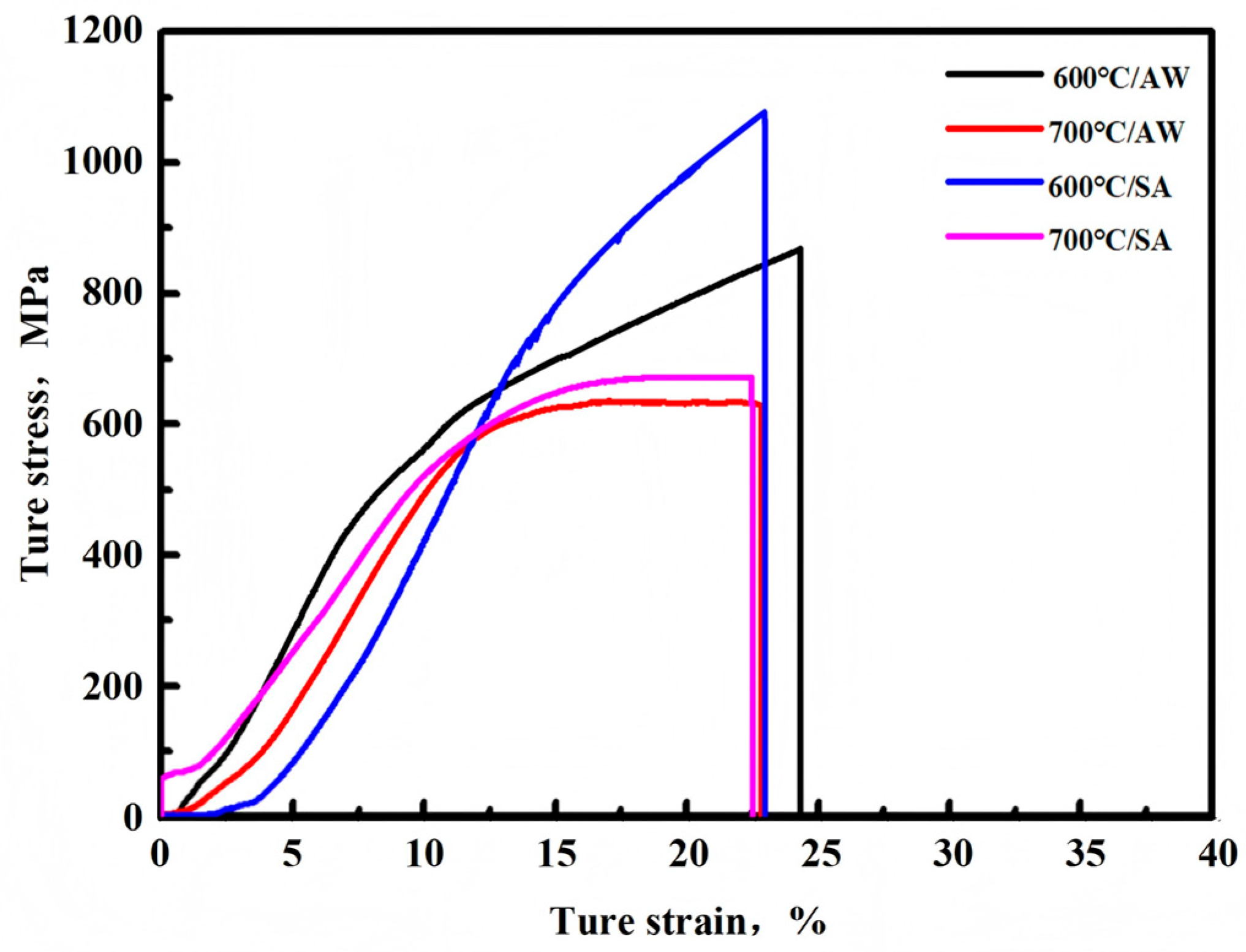
Figure 1. Metallographic determination of the initial melting temperature of the nitrogenous nickel-based deposited metal: (a) 1100 °C/1 h, (b) 1105 °C/1 h, (c) 1110 °C/1 h, (d) 1115 °C/1 h, (e) 1120 °C/1 h, (f) 1130 °C/1 h.
Crystals 15 00509 g001
Figure 2. Typical tensile true stress–strain curves at 600 and 700 °C.
Crystals 15 00509 g002
Figure 3. XRD pattern of nitrogen-containing nickel-based deposited metal.
Crystals 15 00509 g003
Figure 4. SEM morphology of fracture longitudinal section of tensile specimen at 600 °C. (a) AW sample, (b) SA sample.
Crystals 15 00509 g004
Figure 5. TEM bright field image of precipitates in the longitudinal section of the fracture surface of the tensile specimen.(a) M23C6, (b) γʹ phase.
Crystals 15 00509 g005
Figure 6. SEM morphology of fracture longitudinal section of tensile specimen at 700 °C. (a) AW sample, (b) SA sample.
Crystals 15 00509 g006
Figure 7. Tensile fracture characteristics of the nitrogen-containing nickel-based deposited metal at 600 °C. (ad) AW sample, (eh) SA sample.
Crystals 15 00509 g007
Figure 8. Tensile fracture characteristics of the deposited metal at 700 °C. (ad) AW sample, (eh) SA sample.
Crystals 15 00509 g008
Figure 9. BF-TEM images showing deformation microstructures of the nitrogen-containing nickel-based deposited metal. (a) 600 °C/AW, (b) 600 °C/SA, (c) 700 °C/AW, (d) 700 °C/SA.
Crystals 15 00509 g009
Table 1. Tensile performance at 600 °C and 700 °C (AW: as-welded state, SA: solution and aging state).
SampleAW/600 °CSA/600 °CAW/700 °CSA/700 °C
Yield strength (σs/MPa)426.5535.4443.2541.7
Elongation (EL)24.7%23.8%23.5%22.8%
Table 2. Energy spectrum analysis of precipitates at various temperatures (atomic fraction, at%).
SamplePositionNiFeCrNbWCMoTiN
AW/600 °C140.924.725.10.93.10.71.50.52.6
22.71.52.326.13.741.53.95.812.5
323.612.119.114.26.32.614.66.80.7
462.21.65.115.31.23.61.79.00.3
AW/700 °C142.120.227.10.83.90.51.90.43.1
22.81.52.523.14.441.63.76.215.2
323.214.221.113.64.82.412.57.40.8
461.92.74.815.10.72.71.810.20.1
SA/600 °C145.122.822.51.23.10.31.70.42.6
22.61.42.125.83.941.23.15.214.7
363.11.45.215.31.23.11.49.20.1
42.11.92.524.63.841.33.36.214.3
SA/700 °C139.823.128.91.32.40.31.10.22.9
22.71.32.725.23.741.23.35.414.5
363.21.34.815.41.33.21.49.30.1
44.01.860.32.27.213.19.71.40.3
Disclaimer/Publisher’s Note: The statements, opinions and data contained in all publications are solely those of the individual author(s) and contributor(s) and not of MDPI and/or the editor(s). MDPI and/or the editor(s) disclaim responsibility for any injury to people or property resulting from any ideas, methods, instructions or products referred to in the content.

