Article

Mechanistic Decoupling of Giant Electrostrain and Piezoelectric Coefficients at the Morphotropic Phase Boundary in PMN-30PT Single Crystals

1
School of Mechanical Engineering, Qilu University of Technology (Shandong Academy of Sciences), Jinan 250353, China
2
Sichuan Province Key Laboratory of Information Materials and Devices Application, College of Optoelectronic Engineering (Chengdu IC Valley Industrial College), Chengdu University of Information Technology, Chengdu 610225, China
3
Beijing Advanced Innovation Center for Materials Genome Engineering, University of Science and Technology Beijing, Beijing 100083, China
*
Authors to whom correspondence should be addressed.
Crystals 2025, 15(5), 471; https://doi.org/10.3390/cryst15050471
Submission received: 10 April 2025 / Revised: 30 April 2025 / Accepted: 15 May 2025 / Published: 16 May 2025
(This article belongs to the Section Polycrystalline Ceramics)

Abstract

The morphotropic phase boundary (MPB) with multiphase coexistence serves as a critical region for piezoelectric materials, but the individual contributions of various microscopic mechanisms to the overall electromechanical response remains a challenge for further subdivision. Here, we systematically investigate the microscopic origins of outstanding piezoelectricity in <001>-oriented Pb(Mg1/3Nb2/3)O3-30PbTiO3 (PMN-30PT) single crystals and quantitatively identify the dominant factors for giant electrostrain and ultrahigh piezoelectric coefficient. Large electrostrain arises predominantly from polarization rotation within the easily distorted monoclinic phase and the high-energy-barrier monoclinic-to-tetragonal phase transition, enabled by a synergistic interplay of broad electric field adaptability and high strain sensitivity. In contrast, the peak piezoelectric coefficient (d33 > 2100 pC/N) is attributed to the low-energy-barrier rhombohedral-to-monoclinic phase transition, which facilitates polarization rotation. Furthermore, the critical yet distinct roles of monoclinic phase compared to piezoelectric and electrostrain have been confirmed. By the quantitative segmentation of various microscopic factors, this work provides fundamental insights into the design of high-performance piezoelectrics.

1. Introduction

Piezoelectric materials, serving as the cornerstone of modern transducer technologies, enable critical electromechanical energy conversion through their unique ability to generate charges under external stress (d33) or deformation (electrostrain) under an external electric field [1,2,3,4,5]. The discovery of enhanced functional properties at morphotropic phase boundaries (MPBs) with coexisting ferroelectric phases marked a revolutionary advancement in piezoelectric engineering. Seminal studies on PbZr1−xTixO3 (PZT) ceramics, demonstrated exceptional d33~300 pC/N at the rhombohedral-tetragonal (R-T) phase boundary, establishing MPB engineering as a cornerstone of materials design [6,7,8]. Subsequent innovations achieved comparable enhancements through MPB strategies [9,10,11,12,13,14,15,16]. For example, Liu et al. reported d33 = 620 pC/N in BaTiO3-based ceramics via polymorphic phase boundary (PPB) design [9], while Narayan et al. demonstrated 1.3% electrostrain in BiFeO3−PbTiO3−LaFeO3 pseudoternary ceramics through cubic-tetragonal MPB-mediated ferroelastic switching [17]. These breakthroughs fundamentally arise from reduced energy barriers for polarization rotation and domain reconfiguration at multiphase interfaces.
Notably, a critical limitation persists in polycrystalline systems where d33 and electrostrain exhibit intrinsic trade-offs [3,16,17,18,19,20,21,22,23], suggesting distinct mechanistic origins for these parameters, despite their frequent conflation in previous work. This dichotomy stands in stark contrast to relaxor-based single crystals near MPBs, where concurrent enhancement of both properties becomes achievable [24,25,26,27,28]. The landmark work by Park et al. on <001>-oriented PMN-PT and PZN-PT single crystals revealed unprecedented d33 = 2400 pC/N and 1.7% electrostrain, attributed to anisotropic polarization rotation and electric field-induced R-T phase transitions [24]. The mechanistic framework further evolved with identification of metastable monoclinic (M) phases at MPBs [29,30], sparking ongoing debates about dominant mechanisms. While some models emphasize how the M-phase’s expanded polarization orientation space enables low-energy rotation pathways [7,8,31], first-principles calculations by Cohen et al. propose polarization rotation along R-M-T trajectories as the primary driver in relaxor ferroelectrics [32].
This complex interplay reveals that morphotropic phase boundaries (MPBs) host multiple ferroelectric phases that undergo dynamic interconversion and mutual constraints under external stimuli (temperature, electric field, and stress), resulting in intricate evolution of microscopic mechanisms [33,34,35,36]. The fundamental origins of superior piezoelectric performance in such systems remain contentious.
In this study, we systematically investigate the microscopic underpinnings of exceptional piezoelectricity in <001>-oriented Pb(Mg1/3Nb2/3)O3-30PbTiO3 (PMN-30PT) single crystals, quantitatively distinguishing the dominant mechanisms governing giant electrostrain and ultrahigh piezoelectric coefficients. This work can offers fundamental insights into the design of high-performance piezoelectrics.

2. Materials and Methods

The 0.7Pb(Mg1/3Nb2/3)Ti0.3O3-0.3PbTiO3 single crystal rods were commercially purchased from SICCAS High Technology Corporation. The rods were cut along the (001) plane into cubes with dimensions of 5 mm (length) × 5 mm (width) × 1.5 mm (height). Ag electrodes were applied on both sides of the sample for the pre-poling treatments and electrical property measurements.
The temperature dependence of permittivity for the single crystal was measured using an LCR meter (Keysight E4980A, Keysight, Santa Rosa, CA, USA) after pre-polarization treatment for 30 min under a [001] direction electric field of E = 2 kV/cm at room temperature by a DC power supply (Trek 677B). This low polarizing electric field can ensure that the single crystal is in the R phase and with ordered dipole arrangement [37,38,39]. The polarization was measured at different temperatures by a ferroelectric analyzer (TF2000E, aixACCT, Aachen, Germany). In order to study the quantitative contribution of various physical processes, the electric field dependence of permittivity and electrostrain was simultaneously measured by the capacitance–voltage measurement (CVM) of the ferroelectric analyzer, which excitation signal is a continuously changing triangular shaped base waveform of low frequency (1 Hz) with a superimposed high frequency small signal voltage (1000 Hz, 30 V).
The electric field dependence of the permittivity was calculated using the following formula:
ε = Cd/ε0X
where ε is the permittivity, C is the measured capacitance, X is the plate area of the single crystals, d is the sample thickness, and ε0 is the vacuum relative permittivity (8.85 × 10⁻¹² F/m).
The power (Pt) and the energy (Et)were calculated by
Pt = Vt × It
Et = Et−1 + Pt × t
where Vt is the instantaneous testing voltage (V), It is the instantaneous polarization current (A), and t is the time.
The temperature dependence of piezoelectric constant (d33) of was characterized by a Piezo reader (GDPT-900, Beijing JKZC Science and Technology Development Co., Ltd., Beijing, China). The enthalpy change (ΔH) was characterized by a modified differential scanning calorimeter (DSC 250, TA Instruments, New Castle, DE, USA) with a DC power supplier (Trek 677B).

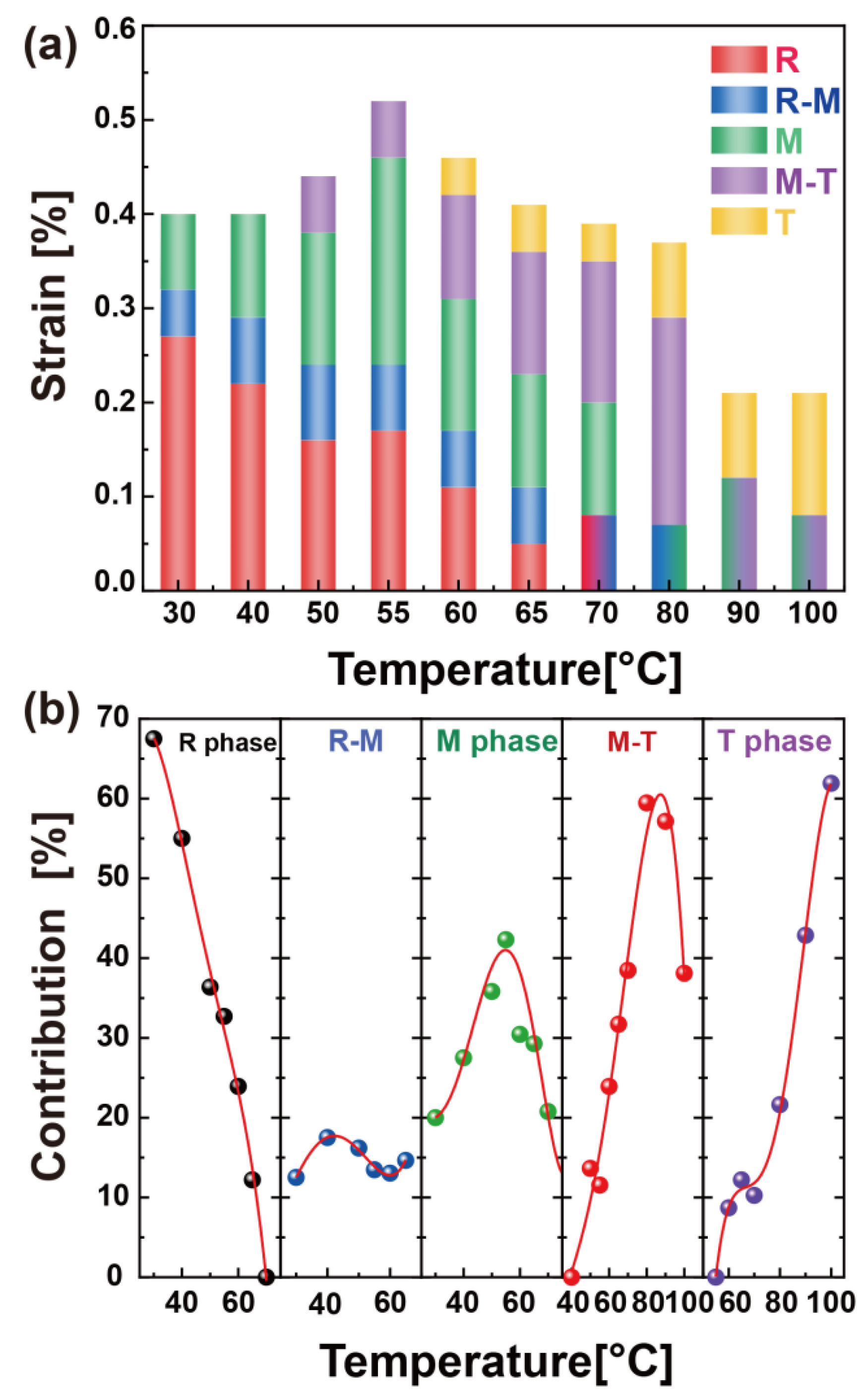
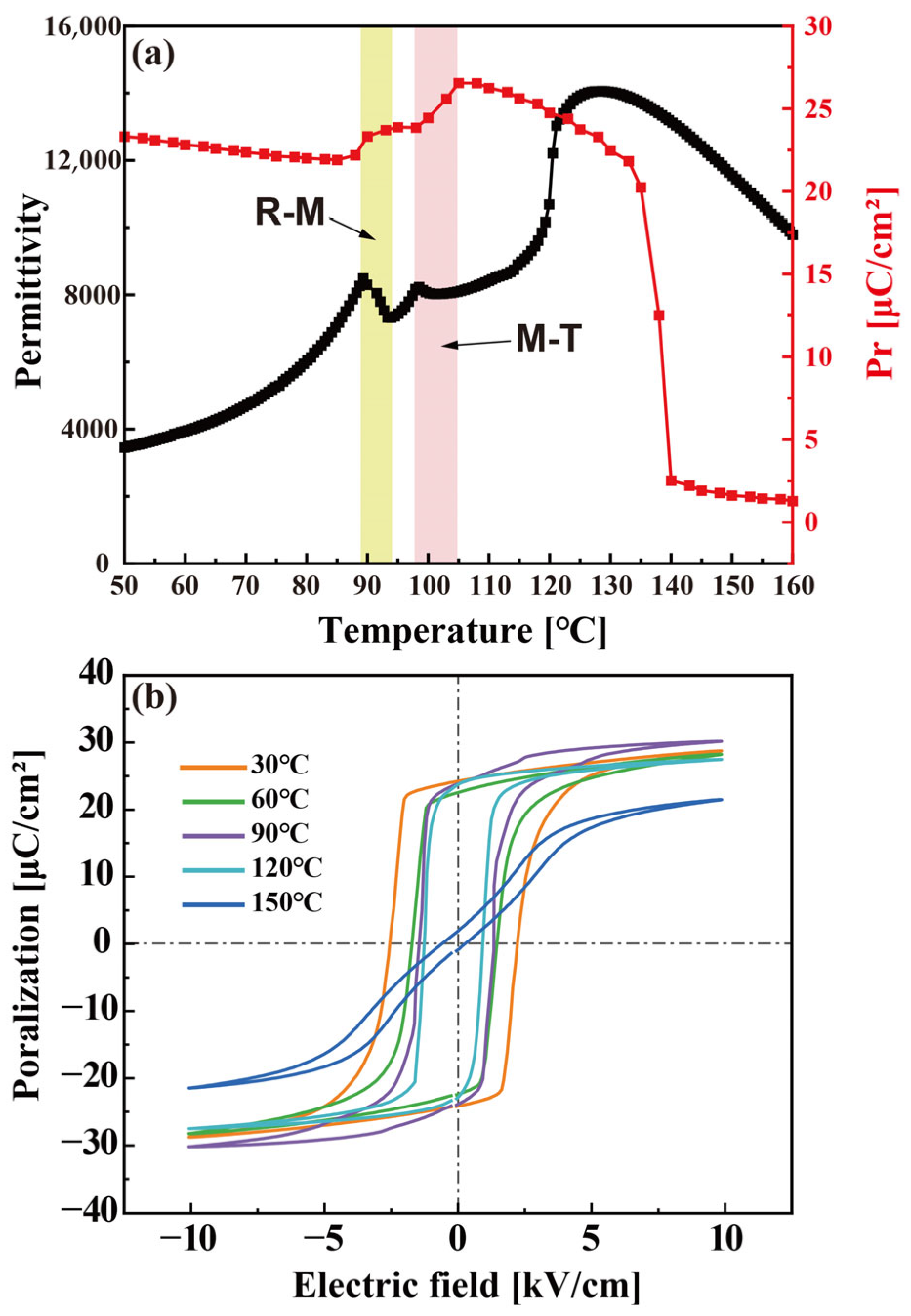
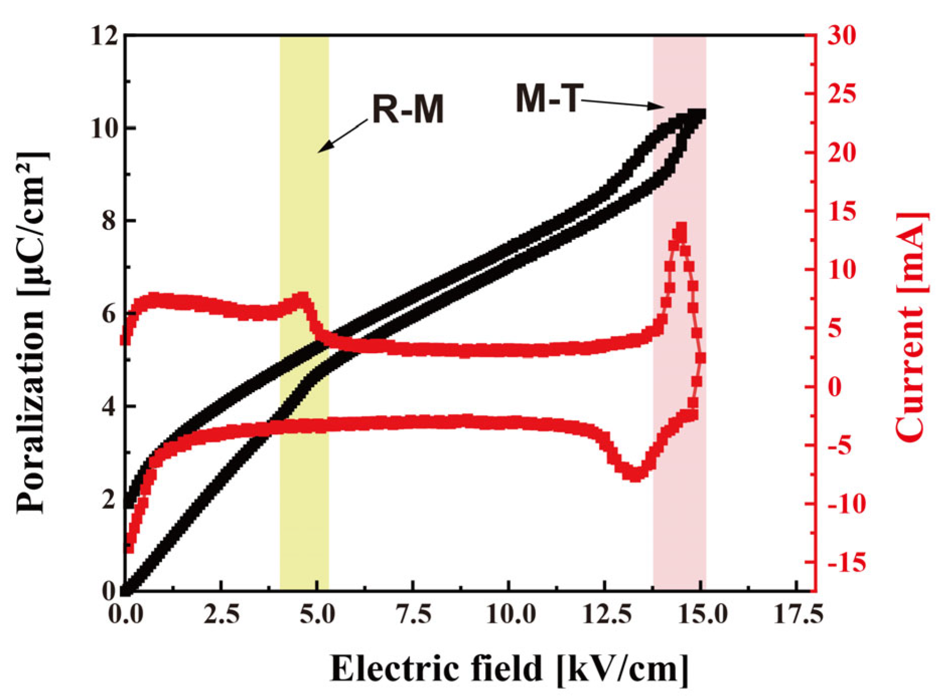
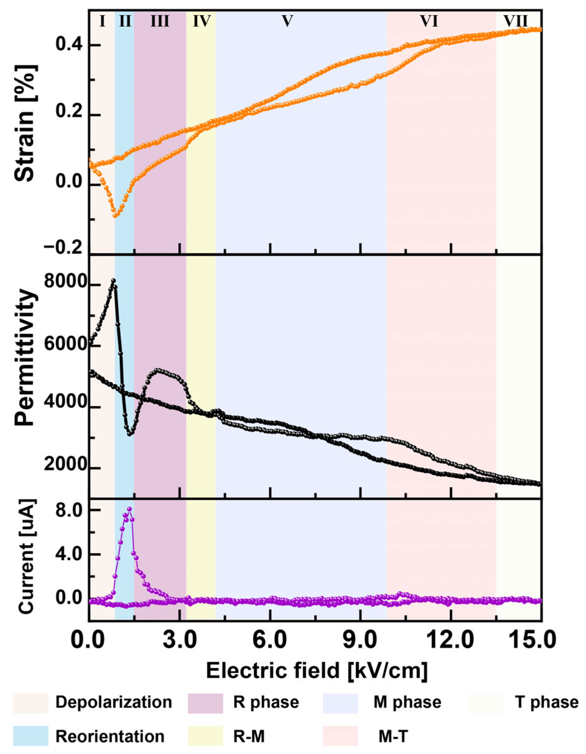
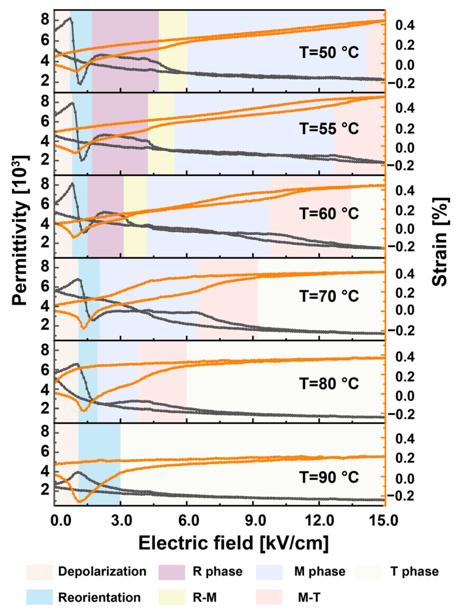
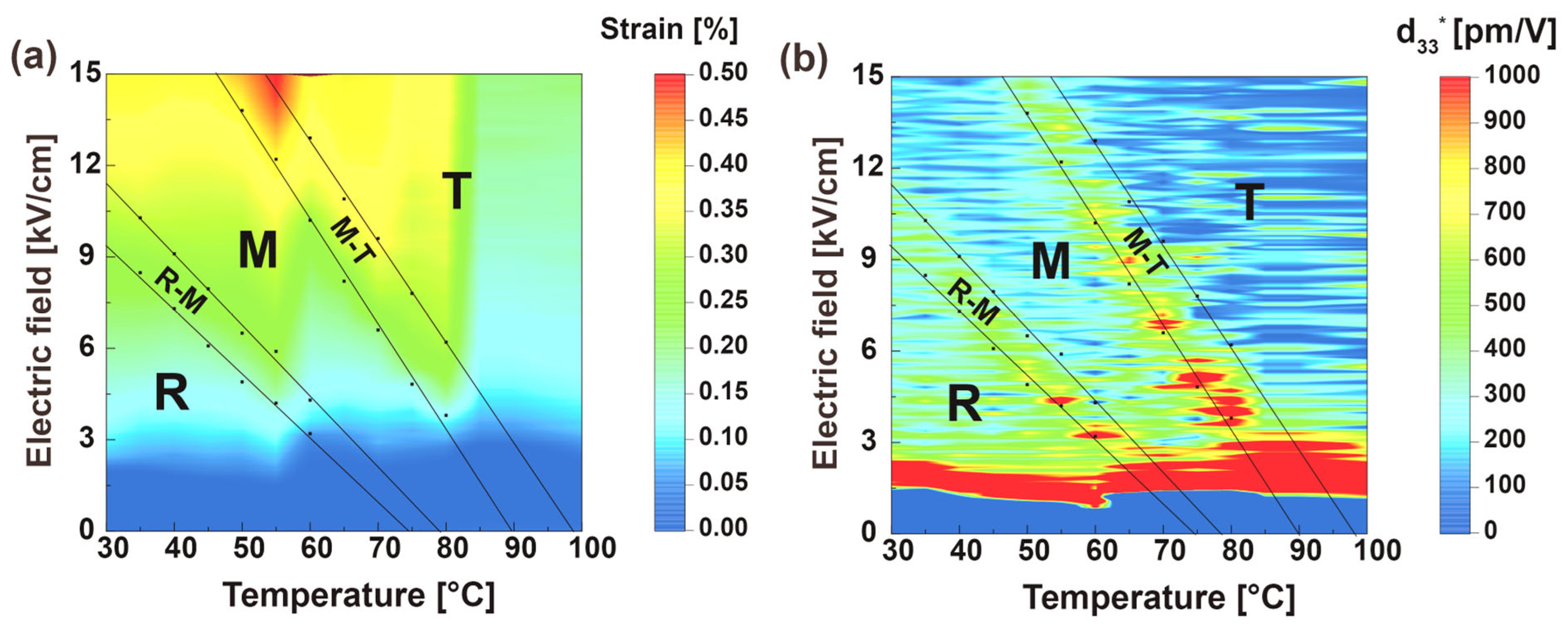
3. Results and Discussion

The commercially obtained <001>-oriented PMN-30PT single crystal adopts a rhombohedral (R) phase at room temperature, its phase structure has been characterized in our previous work [40]. Figure 1a presents the temperature-dependent permittivity of the pre-poled crystal, revealing two distinct anomalies in the low-temperature regime alongside the well-documented high-temperature T-C (cubic) transition. These dielectric singularities correlate systematically with stepwise enhancements in remnant polarization (Pr, the corresponding hysteresis loops are presented in Figure 1b). Such coordinated dielectric and ferroelectric responses strongly support the existence of an intermediate metastable phase during the low-temperature structural evolution from the rhombohedral (R) to tetragonal (T) symmetry. Based on a large number of prior experimental and theoretical results, the intermediate phase has been confirmed to be the monoclinic (M) phase [7,8,30,33,41,42,43]. The three characteristic dielectric peaks can thus be conclusively assigned to sequential phase transitions: R-M at 89 °C, M-T at 97 °C, and T-C above 130 °C.
Notably, analogous multistep transitions emerge under electric-field stimuli. As demonstrated in Figure 2, the polarization rotation trajectory during electric-field-driven R-to-T transformation exhibits two discontinuous jumps in polarization current, accompanied by two peaks in the corresponding current–voltage curve. These features correspond to electric field induced R-M and M-T phase transitions.
This work establishes the M phase as an intrinsic intermediary in both thermally and electrically activated R-T transitions, contrasting with prior reports that overlooked its stability [7,8,27,35,36,42,43,44]. The observed phase transition mechanisms processes are intertwined and highly dependent on the coupling effect of electric-field and temperature, which renders the mechanism complex.
In order to study the quantitative contribution of various physical processes in <001>-oriented PMN-30PT single crystal, the electric-field dependence of permittivity was simultaneously measured with the electrostrain by Capacitance–Voltage Measurement (CVM), as shown in Figure 3. Compared with traditional testing methods such as hysteresis loops and Piezoelectric testing module in ferroelectric analyzers, the CVM can simultaneously provide richer real-time testing information and performance precisely due to its high sensitivity to domain switching and phase transitions. Figure 3 shows the CVM results of <001>-oriented PMN-30PT single crystal at room temperature, where (a)–(f) represent the diagram of the electric field applied by the C-V measurement module, the dielectric constant (calculated using Formula 1 from the measured capacitance), dielectric loss, inverse piezoelectric coefficient (d33*, displacement measured in parallel to the electrical excitation field), polarization current, and electrostrain as a function of electric field, respectively. The variations in dielectric constant, dielectric loss, and inverse piezoelectric coefficient reflect the changes in microscopic mechanisms under small electric field disturbances, while polarization current and electrostrain represent domain switching and phase transitions under large applied bias voltages. For example, when the applied bias field is small, the material undergoes non-180° reversible domain switching, which can exhibit significant changes under small perturbing electric fields. This leads to an increase in the dielectric constant, loss, and inverse piezoelectric coefficient with increasing bias field, while the strain curve shows negative strain. As the field intensity further increases, the single crystal undergoes 180° domain switching, resulting in a sharp decrease in dielectric constant and loss, a change in the inverse piezoelectric coefficient from negative to positive, and the generation of polarization current, while the strain transitions from negative to positive. This indicates that 180° domain switching has little effect on the electrostrain, and also suggests that, in this stage, besides 180° domain switching, there are partial non-180° domain switches from in-plane a/b domains to c domains. This non-180° domain switching is the main reason for the strain transition from negative to zero. During the depolarization and re-polarization processes, the strain variations cancel each other out. At the phase transition point, the transition hinders the continuity of reversible domain switching, leading to a significant reduction in dielectric constant, loss, and inverse piezoelectric coefficient, while the strain increases.
Based on the differences in the electrical response due to domain switching and phase transitions under perturbing electric fields and the base electric field, the polarization path induced by the electric field can be precisely divided into seven contributing regions dominated by different mechanisms. Figure 4 presents the real-time variations in strain, permittivity, and polarization current under the increasing DC electric fields in the <001> PMN-30PT single crystal at a typical temperature of 60 °C, where the R-M-T polarization path is fully displayed. The electrostrain curve exhibits a series of inflection points, which provide signatures to distinguish the physical processes. Notably, the high-sensitivity permittivity measurements (reflecting polarization change rates under AC modulation) provide enhanced resolution for identifying transition thresholds compared to strain monitoring alone. Based on both the electrostrain and permittivity results, seven contributing regions for different physical mechanisms are clearly distinguished in the complete electromechanical process, as shown in Figure 5.
From 0 to 0.8 kV/cm (Region I in Figure 4), the permittivity increases monotonically, and the sample shrinks along the Z direction (the direction of the electric field), i.e., a negative electrostrain, as shown in Figure 5a. This corresponds to a part of polarization switching from the initial -c domain to the in-plane a or b domain, i.e., a depolarization process, where the negative strain is induced by a decreased polarization along the Z axis. If the applied electric field is removed, the sample will revert to its original size, and the polarization vector returns to the -Z axis [45]. The initial regime exhibits monotonic permittivity increase accompanied by negative electrostrain, characteristic of a reversible depolarization reorientation process. Complete strain recovery upon field removal confirms the absence of permanent structural modification in this low-field region.
From 0.8 to 1.6 kV/cm (Region II Figure 4), a sharp permittivity decrease coincides with a prominent polarization current peak, signaling irreversible 180° domain switching activation from c− to c+. The 180° domain switching cannot change the electrostrain [45]. Therefore, the strain change from −0.08% to 0 (Figure 5b) in this region originates from non-180° domain switching, which occurs in the opposite direction to Region I with equivalent strain magnitude. At this point, all polarization directions are aligned with the electric field, indicating reorientation. When the electric field further increases from 1.6 to 3.2 kV/cm (Region III Figure 4), the permittivity turns from rising to falling due to DC field suppression of polarization dynamics. The linear positive electrostrain development with constant 473 pm/V slope (Figure 5c), which indicates the electric-field-induced polarization rotation in the R phase.
Region IV (3.2–4.3 kV/cm): Nonlinear strain acceleration (with a maximum strain rate of 764 pm/V) and permittivity collapse. The abrupt changes in dielectric and strain properties indicate the presence of electric-field-induced structural changes, namely the R-M phase transition [37]. As the electric field increases further, the sample successively experiences polarization elongation in the M phase (slope of 241 pm/V, as shown in Figure 5e), the phase transition from M to T phase (maximum slope of 484 pm/V, as shown in Figure 5f), and polarization elongation in the T phase (slope of 110 pm/V, as shown in Figure 5g). In the M or T single-phase region, the process exhibits similar features to that in the R phase region, while the M-T phase transition is comparable to the R-M phase transition.
This comprehensive analysis identifies three characteristic mechanisms under a bipolar electrical stimulation: (i) non-180° domain switching under reverse polarization (Regions I and II), (ii) polarization vector rotation within individual R, M, and T phase regions (Regions III, V and VII), and (iii) field-driven phase transition processes (Regions IV and VI). Figure 5h summarizes the electrostrain generated by each physical mechanism, with the inset showing the schematic diagrams of the respective mechanisms. During the depolarization and reorientation processes, the strain magnitudes are equal but in opposite directions, so the sum of the strains from these two processes is zero, and their impact on the total strain can be neglected. The total strain primarily originates from polarization rotation and phase transitions induced by the electric field. It is evident that, at 60 °C, the strain magnitudes in each region follow the order: M > M-T > R-M > R > T.
Figure 6 illustrates the evolution of these mechanisms under coupled electric field and temperature. In the testing temperature range, the depolarization and reorientation of polarization switching always exist and the critical fields are almost steady at Ede= ~1.2 kV/cm and Ere= ~2.1 kV/cm. At a low temperature of 40 °C, only the R and M phase, along with their transition, are present. With the increasing temperature, these three regions gradually shift toward lower electric-fields, while the M-T transition and the T phase region emerge above 55 °C. As the temperature increases further, sequential disappearance of the R phase, R-M phase transition, and M phase occurs, accompanied by enhanced T phase dominance.
Through systematic categorization of the various mechanisms illustrated in Figure 6, an electric field–temperature (E-T) phase diagram has been constructed in Figure 7. The R-M and M-T phase transitions exhibit extended electric field–temperature coexistence spans, corresponding to negative-slope phase boundaries with linearly decreasing critical fields as temperature increases, which is consistent with previous reports [37]. Notably, the MPB induced by field–temperature coupling resolves into three distinct regimes: R-M phase transition, intermediate M phase stabilization, and M-T phase transition. Subdividing the MPB region provides an efficient approach to further clarify how the MPB contributes to the ultrahigh electrostrain and piezoelectricity. After projecting both the electrostrain and the inverse piezoelectric coefficient under electric fields onto the phase diagram, as shown in Figure 7a,b, it can be observed that, within the 0–1.5 kV/cm range, the inverse piezoelectric coefficient exhibits negative values, corresponding to the depolarization process of the single crystal. In the range of 1.5–3.0 kV/cm, the inverse piezoelectric coefficient is exceptionally high, corresponding to the re-polarization process. After the depolarization and re-polarization processes are completed, the electrostrain of the single crystal is essentially around 0. When the electric field strength is low (3.0–9.0 kV/cm), the peak electrostrain appears within the R-M and M-T phase transition regions. At the same time, the highest peak of the inverse piezoelectric coefficient consistently occurs in the R-M and M-T phase transition regions. At higher electric field strengths, the peak electrostrain only appears near the M-T phase transition, with the maximum electrostrain occurring at 55 °C. Compared to the R-M phase transition, the M-T phase transition spans a wider electric field range, which facilitates obtaining greater electrostrain. Furthermore, although the inverse piezoelectric coefficient of the intermediate M phase is relatively low, the broader electric field range allows for considerable electrostrain generated by polarization tilt within the M phase.
Figure 8a illustrates the thermally activated evolution of electrostrain under E = 15 kV/cm, including the strain contributions (statistical method shown in Figure 5) of different regions in Figure 6. According to Equation (4), the contribution ratios (η) of different mechanisms are quantitatively described, as shown in Figure 8b.
η = ΔS/Smax
where
η—Contribution ratio of different physical mechanisms to strain;
ΔS—electrostrain generated by different physical mechanisms;
Smax—Total strain of the single crystal under electric field E = 15 kV/cm.
Before the emergence of MPB, the polarization rotation in the R phase serves as the primary factor for the total electrostrain at low temperatures. For example, it accounts for 68% of the total positive electrostrain at 30 °C, as shown in Figure 8b. At low temperature, the polarization elongation in the R phase can be performed over a wide electric-field range, which makes its contribution on the strain larger. When the temperature increases, the strain slope of R phase still increases (as shown in Figure 9a), but the corresponding electric field span decreases sharply, so that its contribution on the strain sharply decreases. When the temperature increases to 55 °C, all polarization processes, except for the polarization rotation in the T phase, contribute to the electrostrain, where the polarization rotation in the M phase (~43%) serve as the most significant contributor to the electrostrain. Although the strain slope induced by polarization rotation in the M phase is smaller than that of neighboring phase transitions, its broader effective electric-field range generates greater electrostrain. When the temperature further increases, the M-T phase transition with both high strain slope and wide electric-field span plays the dominant role (~60%) in the total electrostrain at 80 °C. When the temperature is higher than 90 °C, the intermediate M phase and the M-T phase transition disappear gradually, so that the total electrostrain is dominated by the polarization elongation in T phase, but the magnitude drops significantly, which indicates that the contribution from T phase is not significant.
Figure 8. (a) Quantitative description of various mechanisms contributing to the electrostrain; (b) temperature dependence of respective contributions of various mechanisms for positive electrostrain.
Crystals 15 00471 g008
As shown in Figure 9a, The electrostrain rate hierarchy (phase transitions > polarization rotation within single phase), quantitatively demonstrates the critical role of phase coexistence in achieving superior electromechanical performance. The strain slope exhibits significantly higher values in the R-M and M-T phase transition regions compared to adjacent single-phase regions. This enhancement arises because interphase structural transformations generate greater electrostrain rate than dipole displacement associated with polarization rotation. Figure 9b shows the temperature dependence of the actual piezoelectric constant (weak piezoelectric signal under stress, d33) of the pre-polarized <001> PMN-30PT single crystal. According to the electric-field–temperature phase diagram and the dielectric measurements, the R-M phase transition region produces a d33 peak of 2460 pC/N, but the M-T phase transition does not produce any peak, as shown in Figure 9b. To further study the influence of phase transitions on d33 under multi-fields of electric field and temperature, the actual piezoelectric coefficient d33 was measured immediately after the sample was poled under different electric fields at different temperatures, as shown in Figure 9c. The maximum d33 always occurs in the R-M phase transition region, the peak gradually moves to lower temperatures when the pre-poling electric-field increases, and the trend is generally consistent with the changes in the R-M phase transition region in the E-T phase diagram.
In order to clarify the origins of different piezoelectric performance in the R-M and M-T phase regions, the power, energy consumption and the enthalpy change (∆H) are quantitatively characterized at 55 °C. Figure 9d,e present the electric-field-dependent of the power and energy profiles, respectively. Within the single ferroelectric R or M phase regime, the power exhibits a steady increase with rising electric field strength. Notably, abrupt changes emerge in the power curves at the R-M and M-T phase transition boundaries, where the peak power dissipation reaches approximately 0.008 W and 0.03 W, respectively. As depicted in Figure 9e, the energy consumption under cyclic electric fields provides a quantitative measure of the phase transition energetics: the R-M transition requires approximately 0.016 J of electrical energy, while the M-T transition demands approximately 0.057 J. From the perspective of electrocaloric effects [37,44,46], the R-M and M-T phase transitions undergo an enthalpy change of −0.017 J/g and −0.061 J/g, which agrees well with the changes in free energy. The electrical energy consumption and the enthalpy change of the M-T phase transition are 3 times those of the R-M phase, which is consistent with the previous calculation of the free energy barrier by Cohen et al. [32].
Quantitative analysis of energy characteristics in R-M and M-T phase transitions reveals distinct potential barrier profiles. The R-M transition exhibits a lower energy barrier, whereas the M-T transition demonstrates a substantially higher energy barrier. Under applied stress conditions, the mechanical energy provided by stress exceeds the R-M energy barrier, enabling reversible phase transformation between R and M phases. This energy-accessible transition facilitates polarization vector rotation through enhanced switching probabilities, thereby inducing an ultrahigh piezoelectric coefficient (d33) in the R-M phase coexistence region. In contrast, the high M-T energy barrier creates an insurmountable energy threshold under equivalent stress conditions, suppressing phase transformation dynamics between M and T phases. Consequently, the M-T transition fails to contribute to d33 enhancement, as evidenced by the absence of piezoelectric response peaks in this regime [27,38]. These findings establish that among electric field- and temperature-induced polarization rotation mechanisms, the R-M phase transition and its associated coexistence region serve as the predominant contributors to giant d33 performance, governed by their flat energy landscape characteristics.
Although piezoelectric coefficient (d33) and electrostrain (or d33*) are conventionally treated as interchangeable parameters in piezoelectric systems, our findings reveal fundamentally different dominant mechanisms underlying these properties, as systematically demonstrated in Table 1. For the piezoelectricity, the R-M phase transition is always the dominant factor. The R-M phase transition region can be regarded as an electric-field-induced MPB with a flat free energy profile, and the low energy barrier of R-M phase transition provides more possibility of polarization direction, both of which induce the high d33. For the electrostrain, the polarization elongation in the R phase, in the M phase and the M-T phase transition successively play the dominant role with the increasing temperature because the electrostrain can be regarded as a product effect of strain rate and electric-field span. Due to respective determinants, different strategies should be implemented for materials designs towards high piezoelectricity and large electrostrain. This finding explains why high piezoelectric coefficients and giant electrostrictive strains generally cannot coexist in most materials.
These results further confirm the critical yet distinct roles of the M phase in piezoelectric responses. For the d33, the M phase reduces the energy barrier between R and T phases, flattening the R-M phase boundary energy landscape. This explains why d33 peaks exclusively emerge on the R phase side of the MPB in the PMN-xPT single crystal system. For the electrostrain, the M phase broadens the electric field span of R-T transitions and enhances the strain rates through phase transition activation, thereby enabling superior electrostrain responses in <001>-oriented ferroelectric single crystals.

4. Conclusions

In summary, we systematically studied the microscopic origins of outstanding piezoelectricity in <001>-oriented PMN-30PT single crystals and quantitatively identified the distinct mechanistic origins of the giant electrostrain and ultrahigh d33. Large electrostrain arises predominantly from polarization rotation within the easily distorted monoclinic phase and the high-energy-barrier monoclinic-to-tetragonal phase transition, enabled by a synergistic interplay of broad electric field adaptability and high strain sensitivity. In contrast, the peak piezoelectric coefficient (d33 > 2100 pC/N) is attributed to the low-energy-barrier rhombohedral-to-monoclinic phase transition, which facilitates polarization rotation. This work further confirms the critical yet distinct roles of the M phase in piezoelectric responses. By clarifying the key factors for electrostrain and piezoelectric constant, this work provides a deeper insight into the physical origins for the design of high-performance piezoelectrics at the MPB.

Author Contributions

Writing—original draft, R.Y. and J.L. (Jianting Li); Methodology, R.Y. and J.L. (Jianting Li); Investigation, S.L.; Writing—review and editing, J.L. (Jianting Li), W.-F.R. and Y.B.; Funding acquisition, J.L. (Jianting Li) and W.-F.R.; Data curation, J.L. (Jianting Li); Conceptualization, J.L. (Junjie Li).; Formal analysis, Y.Y. All authors have read and agreed to the published version of the manuscript.

Funding

This work was supported by the National Natural Science Foundation of China (NO. 12174210, 52402149), the Natural Science Foundation of Shandong Province (NO. ZR2022QE078) and the Basic Research Project of Qilu University of Technology (NO. 2024RCKY020). Li also acknowledges the Guangdong Provincial Key Laboratory of Electronic Functional Materials and Devices (NO. EFMD2022013M).

Data Availability Statement

The original contributions presented in the study are included in the article, further inquiries can be directed to the corresponding author.

Conflicts of Interest

The authors declare no conflicts of interest.

References

  1. Zheng, T.; Wu, J.; Xiao, D.; Zhu, J. Recent development in lead-free perovskite piezoelectric bulk materials. Prog. Mater. Sci. 2018, 98, 552–624. [Google Scholar] [CrossRef]
  2. Hao, J.; Li, W.; Zhai, J.; Chen, H. Progress in high-strain perovskite piezoelectric ceramics. Mater. Sci. Eng. R Rep. 2019, 135, 1–57. [Google Scholar] [CrossRef]
  3. Lv, X.; Zhu, J.; Xiao, D.; Zhang, X.-X.; Wu, J. Emerging new phase boundary in potassium sodium-niobate based ceramics. Chem. Soc. Rev. 2020, 49, 671–707. [Google Scholar] [CrossRef] [PubMed]
  4. Acosta, M.; Novak, N.; Rojas, V.; Patel, S.; Vaish, R.; Koruza, J.; Rossetti, G.A.; Rödel, J. BaTiO3-based piezoelectrics: Fundamentals, current status, and perspectives. Appl. Phys. Rev. 2017, 4, 041305. [Google Scholar] [CrossRef]
  5. Gao, Z.; Lei, Y.; Li, Z.; Yang, J.; Yu, B.; Yuan, X.; Hou, Z.; Hong, J.; Dong, S. Artificial piezoelectric metamaterials. Prog. Mater. Sci. 2025, 151, 101434. [Google Scholar] [CrossRef]
  6. Jaffe, B.S.; Roth, R.S.; Marzullo, S. Piezoelectric Properties of Lead Zirconate-Lead Titanate Solid-Solution Ceramics. J. Appl. Phys. 1954, 25, 809–810. [Google Scholar] [CrossRef]
  7. Liu, H.; Chen, J.; Fan, L.; Ren, Y.; Pan, Z.; Lalitha, K.V.; Rödel, J.; Xing, X. Critical Role of Monoclinic Polarization Rotation in High-Performance Perovskite Piezoelectric Materials. Phys. Rev. Lett. 2017, 119, 017601. [Google Scholar] [CrossRef]
  8. Fan, L.; Chen, J.; Ren, Y.; Pan, Z.; Zhang, L.; Xing, X. Unique Piezoelectric Properties of the Monoclinic Phase in Pb (Zr,Ti)O3 Ceramics: Large Lattice Strain and Negligible Domain Switching. Phys. Rev. Lett. 2016, 116, 027601. [Google Scholar] [CrossRef]
  9. Liu, W.; Ren, X. Large Piezoelectric Effect in Pb-Free Ceramics. Phys. Rev. Lett. 2009, 103, 257602. [Google Scholar] [CrossRef]
  10. Ma, C.; Guo, H.; Beckman, S.; Tan, X. Creation and Destruction of Morphotropic Phase Boundaries through Electrical Poling: A Case Study of Lead-Free (Bi1/2Na1/2)TiO3-BaTiO3 Piezoelectrics. Phys. Rev. Lett. 2012, 109, 107602. [Google Scholar] [CrossRef]
  11. Liu, X.; Tan, X. Giant Strains in Non-Textured (Bi1/2Na1/2)TiO3-Based Lead-Free Ceramics. Adv. Mater. 2016, 28, 574–578. [Google Scholar] [CrossRef] [PubMed]
  12. Zhang, M.H.; Thong, H.C.; Jiang, B.; Zhang, N.; Zhao, C.; Wu, Z.; Zhou, T.; Wu, C.; Yao, F.; Bi, K.; et al. Field-Induced Polarization Rotation in Order–Disorder (K,Na)NbO3-Based Ferroelectrics. Adv. Mater. 2024, 37, 2413587. [Google Scholar] [CrossRef] [PubMed]
  13. Wang, J.; Wang, S.; Li, X.; Li, L.; Liu, Z.; Zhang, J.; Wang, Y. High piezoelectricity and low strain hysteresis in PMN–PT-based piezoelectric ceramics. J. Adv. Ceram. 2023, 12, 792–802. [Google Scholar] [CrossRef]
  14. Liu, H.; Zhang, Q.; Luo, H.; Zhu, J. Direct observations of electric-field-induced domain switching and phase transition in 0.95Na0.5Bi0.5TiO3-0.05BaTiO3 single crystals using in situ transmission electron microscopy. Appl. Phys. Lett. 2022, 120, 072901. [Google Scholar] [CrossRef]
  15. Li, T.; Liu, C.; Shi, P.; Liu, X.; Kang, R.; Long, C.; Wu, M.; Cheng, S.; Mi, S.; Xia, Y.; et al. High-Performance Strain of Lead-Free Relaxor-Ferroelectric Piezoceramics by the Morphotropic Phase Boundary Modification. Adv. Funct. Mater. 2022, 32, 2202307. [Google Scholar] [CrossRef]
  16. Yin, X.; Chen, C.; Fan, Z.; Qin, M.; Zeng, M.; Lu, X.; Zhou, G.; Gao, X.; Chen, D.; Liu, J.-M. Coexistence of multiple morphotropic phase boundaries in strained La-doped BiFeO3 thin films. Mater. Today Phys. 2021, 17, 100345. [Google Scholar] [CrossRef]
  17. Narayan, B.; Malhotra, J.S.; Pandey, R.; Yaddanapudi, K.; Nukala, P.; Dkhil, B.; Senyshyn, A.; Ranjan, R. Electrostrain in excess of 1% in polycrystalline piezoelectrics. Nat. Mater. 2018, 17, 427–431. [Google Scholar] [CrossRef]
  18. Nie, X.; Jing, R.; Yang, Y.; Yan, Y.; Laletin, V.; Shur, V.; Wang, G.; Jin, L. Optimized electrostrain with minimal hysteresis at the MPB in BNT-based ceramics. J. Eur. Ceram. Soc. 2025, 45, 117073. [Google Scholar] [CrossRef]
  19. Muleta, G.J.; Adhikary, G.D.; Ranjan, R. Structural aspects of the ferroelectric, weak-field piezoelectric, and electrostrain responses in Sr, Nb modified Na0.5Bi0.5TiO3-K0.5Bi0.5TiO3. Acta Mater. 2025, 288, 120825. [Google Scholar] [CrossRef]
  20. Lin, J.; Lv, F.; Hong, Z.; Liu, B.; Wu, Y.; Huang, Y. Ultrahigh Piezoelectric Response Obtained by Artificially Generating a Large Internal Bias Field in BiFeO3–BaTiO3 Lead-Free Ceramics. Adv. Funct. Mater. 2024, 34, 2313879. [Google Scholar] [CrossRef]
  21. Xu, K.; Li, J.; Lv, X.; Wu, J.; Zhang, X.-X.; Xiao, D.-Q.; Zhu, J. Superior Piezoelectric Properties in Potassium–Sodium Niobate Lead-Free Ceramics. Adv. Mater. 2016, 28, 8519–8523. [Google Scholar] [CrossRef] [PubMed]
  22. Jing, R.; Zhang, L.; Hu, Q.; Alikin, D.O.; Shur, V.Y.; Wei, X.; Zhang, L.; Liu, G.; Zhang, H.; Jin, L. Phase evolution and relaxor to ferroelectric phase transition boosting ultrahigh electrostrains in (1−x)(Bi1/2Na1/2)TiO3-x(Bi1/2K1/2)TiO3 solid solutions. J. Mater. 2022, 8, 335–346. [Google Scholar] [CrossRef]
  23. Li, F.; Jin, L.; Xu, Z.; Zhang, S. Electrostrictive effect in ferroelectrics: An alternative approach to improve piezoelectricity. Appl. Phys. Rev. 2014, 1, 011103. [Google Scholar] [CrossRef]
  24. Zhang, S.; Li, F.; Jiang, X.; Kim, J.; Luo, J.; Geng, X. Advantages and challenges of relaxor-PbTiO3 ferroelectric crystals for electroacoustic transducers—A review. Prog. Mater. Sci. 2015, 68, 1–66. [Google Scholar] [CrossRef]
  25. Zheng, L.; Lu, X.; Shang, H.; Xi, Z.; Wang, R.; Wang, J.; Zheng, P.; Cao, W. Hysteretic phase transition sequence in 0.67Pb(Mg1/3Nb2/3)O3−0.33PbTiO3 single crystal driven by electric field and temperature. Phys. Rev. B. 2015, 91, 184105. [Google Scholar] [CrossRef]
  26. Li, F.; Cabral, M.J.; Xu, B.; Cheng, Z.; Dickey, E.C.; Lebeau, J.M.; Wang, J.; Luo, J.; Taylor, S.; Hackenberger, W.; et al. Giant piezoelectricity of Sm-doped Pb(Mg1/3Nb2/3)O3-PbTiO3 single crystals. Science 2019, 364, 264–268. [Google Scholar] [CrossRef]
  27. Park, S.-E.; Shrout, T.R. Ultrahigh strain and piezoelectric behavior in relaxor based ferroelectric single crystals. J. Appl. Phys. 1997, 82, 1804–1811. [Google Scholar] [CrossRef]
  28. Li, J.; Li, J.; Wu, H.; Zhou, O.; Chen, J.; Lookman, T.; Su, Y.; Qiao, L.; Bai, Y. Influence of Phase Transitions on Electrostrictive and Piezoelectric Characteristics in PMN-30PT Single Crystals. ACS Appl. Mater. Interfaces 2021, 13, 38467–38476. [Google Scholar] [CrossRef]
  29. Noheda, B.; Cox, D.E.; Shirane, G.; Park, S.E.; Cross, L.E.; Zhong, Z. Polarization Rotation via a Monoclinic Phase in the Piezoelectric 92% PbZn1/3Nb2/3O3-8% PbTiO3. Phys. Rev. Lett. 2001, 86, 3891–3894. [Google Scholar] [CrossRef]
  30. Ye, Z.; Noheda, B.; Dong, M.; Cox, D.; Shirane, G. Monoclinic phase in the relaxor-based piezoelectric/ferroelectric Pb(Mg1/3Nb2/3)O3−PbTiO3 system. Phys. Rev. B. 2001, 64, 184114. [Google Scholar] [CrossRef]
  31. Guo, R.; Cross, L.E.; Park, S.-E.; Noheda, B.; Noheda, B.; Cox, D.E.; Shirane, G. Origin of the high piezoelectric response in PbZr1-xTixO3. Phys. Rev. Lett. 1999, 84, 5423. [Google Scholar] [CrossRef] [PubMed]
  32. Fu, H.; Cohen, R.E. Polarization rotation mechanism for ultrahigh electromechanical response in single-crystal piezoelectrics. Nature 2000, 403, 281–283. [Google Scholar] [CrossRef] [PubMed]
  33. Davis, M.; Damjanovic, D.; Setter, N. Electric-field-, temperature-, and stress-induced phase transitions in relaxor ferroelectric single crystals. Phys. Rev. B. 2006, 73, 014115. [Google Scholar] [CrossRef]
  34. Liu, Y.; Xia, J.; Finkel, P.; Moss, S.D.; Liao, X.; Cairney, J.M. Real-time observation of stress-induced domain evolution in a [011] PIN-PMN-PT relaxor ferroelectric single crystal. Acta Mater. 2019, 175, 436–444. [Google Scholar] [CrossRef]
  35. Webber, K.; Zuo, R.; Lynch, C. Ceramic and single-crystal (1–x)PMN–xPT constitutive behavior under combined stress and electric field loading. Acta Mater. 2008, 56, 1219–1227. [Google Scholar] [CrossRef]
  36. Schader, F.H.; Rossetti, G.A.; Luo, J.; Webber, K.G. Piezoelectric and ferroelectric properties of <001>C Pb(In1/2Nb1/2)O3-Pb(Mg1/3Nb2/3)O3-PbTiO3 single crystals under combined thermal and mechanical loading. Acta Mater. 2017, 126, 174–181. [Google Scholar] [CrossRef]
  37. Li, J.; Yin, R.; Su, X.; Wu, H.-H.; Li, J.; Qin, S.; Sun, S.; Chen, J.; Su, Y.; Qiao, L.; et al. Complex phase transitions and associated electrocaloric effects in different oriented PMN-30PT single crystals under multi-fields of electric field and temperature. Acta Mater. 2020, 182, 250–256. [Google Scholar] [CrossRef]
  38. Rajan, K.; Shanthi, M.; Chang, W.; Jin, J.; Lim, L. Dielectric and piezoelectric properties of [001] and [011]-poled relaxor ferroelectric PZN–PT and PMN–PT single crystals. Sens. Actuators A Phys. 2007, 133, 110–116. [Google Scholar] [CrossRef]
  39. Zhao, X.; Fang, B.; Cao, H.; Guo, Y.; Luo, H. Dielectric and piezoelectric performance of PMN–PT single crystals with compositions around the MPB: Influence of composition, poling field and crystal orientation. Mater. Sci. Eng. B. 2002, 96, 254–262. [Google Scholar] [CrossRef]
  40. Zhang, Y.; Gong, W.; Li, Z.; Li, J.; Li, C.; Chen, J.; Yang, Y.; Bai, Y.; Rao, W.-F. Two Consecutive Negative Electrocaloric Peaks in <001>-Oriented PMN-30PT Single Crystals. Crystals. 2024, 14, 458. [Google Scholar]
  41. Wu, H.; Cohen, R.E. Electric-field-induced phase transition and electrocaloric effect in PMN-PT. Phys. Rev. B. 2017, 96, 054116. [Google Scholar] [CrossRef]
  42. Xu, G.; Luo, H.; Xu, H.; Yin, Z. Third ferroelectric phase in PMNT single crystals near the morphotropic phase boundary composition. Phys. Rev. B. 2001, 64, 020102. [Google Scholar] [CrossRef]
  43. Fang, F.; Yang, W.; Luo, X. [101]-Oriented Pb(Mg1/3Nb2/3)O3–PbTiO3 Single Crystals Under Electric Loadings: Polarization Rotation Linking MB, O, and R Phases. J. Am. Ceram. Soc. 2010, 93, 3916–3920. [Google Scholar] [CrossRef]
  44. Liao, L.; Shan, D.; Lei, C.; Pan, K.; Li, J.; Liu, Y. Revealing the mechanisms of electrocaloric effects by simultaneously direct measuring local electrocaloric and electrostrain under ambient conditions. Acta Mater. 2024, 278, 120264. [Google Scholar] [CrossRef]
  45. Dou, J.; Li, J.; Li, J.; Zhang, H.; Yang, Y.; Bai, Y.; Rao, W.-F. Simultaneous enhancement of the electrocaloric effect and electrostrain via exploiting the reversible polarization rotation. Ceram. Int. 2023, 49, 7094–7098. [Google Scholar] [CrossRef]
  46. Li, J.; Qin, S.; Bai, Y.; Li, J.; Qiao, L. Flexible control of positive and negative electrocaloric effects under multiple fields for a giant improvement of cooling capacity. Appl. Phys. Lett. 2017, 111, 093901. [Google Scholar] [CrossRef]
Figure 1. (a) Temperature dependence of permittivity (black curve) and remnant polarization (Pr, red curve) for the pre-poled <001>-oriented PMN-30PT single crystal; (b) bipolar hysteresis loops of <001>-oriented PMN-30PT single crystal at different temperatures.
Crystals 15 00471 g001
Figure 2. Hysteresis loops (black curve) and polarization current (red curve) for the pre-poled <001>-oriented PMN-30PT single crystal at 60 °C.
Crystals 15 00471 g002
Figure 3. The C-V test results of <001>-oriented PMN-30PT single crystal at room temperature: (a) schematic diagram of the electric field applied by the Capacitance–Voltage (C-V) measurement module; (b) permittivity electric field curve; (c) dielectric loss-electric field curve; (d) inverse piezoelectric constant-electric field strength curve; (e) polarization current-electric field curve; (f) electric strain electric field strength curve. The basic electric field increased from 0 to 15 kV/cm with a frequency of 1 Hz, while the AC disturbance small signal size was 30 V with a frequency of f = 1000 Hz.
Crystals 15 00471 g003
Figure 4. Electric field dependence of electrostrain, permittivity and polarization current in <001> PMN-30PT single crystal at 60 °C.
Crystals 15 00471 g004
Figure 5. Electrostrain in different physical process of <001>-oriented PMN-30PT single crystal at 60 °C: (a) depolarization process; (b) reorientation process; (c) R-phase polarization tilt; (d) R-M phase transition region; (e) M-phase polarization tilt; (f) M-T phase transition region; (g) polarization tilt within T; (h) comparison of electrostrain generated by different physical mechanisms.
Crystals 15 00471 g005
Figure 6. Electric field dependence of electrostrain, permittivity and polarization current in <001> PMN-30PT single crystal at different temperature.
Crystals 15 00471 g006
Figure 7. (a) Electrostrain and (b) electric-field-induced inverse piezoelectric constant d33* = dS/dE in the electric field–temperature phase diagram for <001> PMN-30PT single crystals. The symbols are experimental points obtained from the permittivity and electrostrain measurements in Figure 6, and the lines are linear fits.
Crystals 15 00471 g007
Figure 9. (a) Strain slope in different regions; (b) temperature dependence of actual piezoelectric coefficient d33 of the pre-polarized <001> PMN-30PT single crystal and (c) its variation for different poling electric-fields; (d) the electrostrain curve and the corresponding power and (e) the corresponding energy consumption under E = 15 kV/cm at 55 °C, as well as (f) the enthalpy change.
Crystals 15 00471 g009
Table 1. Respective contribution analysis for piezoelectricity and electrostrain.
PropertyPiezoelectricityElectrostrain
Dominant factor
R-M phase transition
Polarization elongation in R phase
Polarization elongation in M phase
M-T phase transition
Conditions
Low fields
High fields
Requirements
Flat thermodynamic energy profile
Wide electric field span and large energy barrier
Disclaimer/Publisher’s Note: The statements, opinions and data contained in all publications are solely those of the individual author(s) and contributor(s) and not of MDPI and/or the editor(s). MDPI and/or the editor(s) disclaim responsibility for any injury to people or property resulting from any ideas, methods, instructions or products referred to in the content.

