Article

In Situ Observation of Microwave Sintering-Induced Directional Pores in Lithium Cobalt Oxide for Vertical Microchannel Electrodes

CAS Key Laboratory of Mechanical Behaviour and Design of Materials, Department of Modern Mechanics, CAS Center for Excellence in Complex System Mechanics, University of Science and Technology of China, Hefei 230027, China
*
Author to whom correspondence should be addressed.
Crystals 2025, 15(4), 368; https://doi.org/10.3390/cryst15040368
Submission received: 12 March 2025 / Revised: 7 April 2025 / Accepted: 9 April 2025 / Published: 17 April 2025
(This article belongs to the Special Issue Electrode Materials in Lithium-Ion Batteries)

Abstract

:
As an efficient energy storage solution, lithium-ion batteries (LIBs) play a crucial role in the electric vehicle sector, driving innovation and development in the automotive industry. One common strategy to enhance energy density is to manufacture thicker electrodes. However, the pore distribution in thicker electrodes is often suboptimal, with elongated and tortuous pathways impeding charge transport. Optimizing the pore structure in electrodes is essential for fabricating high-performance batteries. In this study, we performed microwave sintering on lithium cobalt oxide materials and observed the three-dimensional evolution of pores during the sintering process using synchrotron radiation computed tomography (SR-CT).We discovered that pore evolution exhibits directional characteristics. Further analysis revealed that the electromagnetic loss of particles is related to the direction of the electric field, which is the reason for the directional behavior of pore evolution. This research could provide a new potential approach for the fabrication of advanced electrode materials by using electric field control during the battery manufacturing process to align pores vertically, thereby improving both the energy density and charge–discharge rate of the battery.

1. Introduction

As one of the most promising energy storage systems, lithium-ion batteries are the most widely used type of battery in transportation, electronic communications, medicine, and various other fields. Lithium batteries demand higher energy density and power density for long mileage and quick charging [1,2,3]. Increasing the electrode thickness to increase the proportion of active materials in batteries is a common strategy for enhancing battery energy density [4,5]. However, thicker electrodes would impede ion transmission efficiency due to extended pore paths and increased tortuosity, reducing electrode power density. Additionally, increasing the electrode thickness can decrease mechanical stability, resulting in electrolyte cracking or delamination in the battery [6,7,8]. A promising approach is eliminating conductive agents and binders from electrode materials and directly sintering them to achieve high-density electrodes [9,10]. Sintered electrodes exhibit superior mechanical strength compared to conventional ones and effectively increase the proportion of active materials [11,12,13]. Nonetheless, there is an inherent trade-off between the high density and high porosity of sintered electrodes. Increased electrode density inevitably reduces porosity, thereby diminishing ion transport efficiency [14,15].
Recent studies have indicated that optimizing the electrode microstructure can enhance ion transport efficiency [16,17,18]. Among these microstructure parameters, electrode tortuosity stands out as a critical parameter influencing battery performance. Various approaches, such as stencils and magnetic field control, have been employed to create directional microchannels aimed at minimizing tortuosity [19]. Using sintered electrodes with microchannels poses challenges due to limitations inherent in traditional electrode preparation methods. The microchannels significantly increase electrode porosity, resulting in a lower actual energy density compared to traditional electrodes [20]. Therefore, the main current challenge is how to reduce electrode tortuosity by controlling pore space distribution while maintaining a certain porosity level [21].
In this study, we conducted microwave sintering of lithium cobalt oxide electrodes. During the preparation process, the direction of pores evolution was controlled by the electric field. Ultimately, this forms directionally interconnected pores to reduce the tortuosity of electrodes. During the sintering process, vertical connectivity decreases to 59% of its initial state, while horizontal connectivity decreases to 72% of its initial state, indicating that transverse connectivity is significantly better preserved. Synchrotron radiation imaging technology enabled the observation of three-dimensional interconnected pore evolution during the sintering process.
We found that pore evolution exhibited directional characteristics, with vertical pores shrinking and closing more rapidly, while horizontal pores were selectively protected. To elucidate the evolution mechanism, further analysis revealed that the electromagnetic losses of particles correlate with the direction of the electric field, which causes directional pores evolution. The study provides insights into preparing high-performance advanced electrode materials with various anisotropic properties.

2. Materials and Methods

2.1. Lithium Cobalt Oxide Materials

The lithium cobalt oxide particles initially came in a powdered form, purchased from Jiewei Power Industry Co., Ltd., Tianjin City, China, with particle sizes ranging between 10 and 15 μm. The particles were placed into a quartz glass tube with a length of 2 mm and a diameter of 1 mm to create the sample.

2.2. Sample Sintering

The microwave sintering system operates at a frequency of 2.45 GHz with an output power range of 0 to 3 kW, generating a single-mode standing wave pattern in the microwave resonant cavity. Figure 1 shows the microwave sintering equipment. Samples are positioned vertically at the location of the maximum electric field in the microwave sintering cavity. The microwave resonant cavity has openings on all sides (top, bottom, front, and back): X-ray penetration of samples through front and back apertures. The samples are placed on a sintering boat, with the drive shaft connected above the boat and linked to the rotating table below through a hole, allowing the sample to rotate along with the turntable during the sintering process.

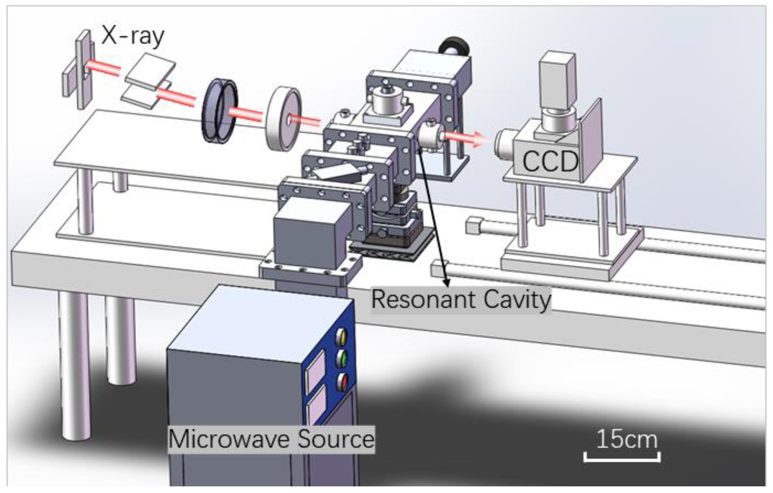
2.3. Synchrotron Radiation CT Imaging

This experiment was conducted at the BL09b beamline of the Shanghai Synchrotron Radiation Facility (SSRF), Shanghai, China. High-speed tomographic imaging of the sintering process was achieved through independent operations, including high-speed rotation of the turntable and camera projection capture. The sample rotates at a constant speed of 180 rpm under the drive of gas-bearing turntable bearings. The camera has an image size of 2048 × 2048 pixels, a spatial resolution of 1.8125 μm/pixel. The sample is imaged every 1° as it rotates 180° for each state, with an interval time of 167 ms between each CT state. Using SR-CT to irradiate the sample primarily aims at measuring the absorption of X-rays as they pass through the sample. This allows for the reconstruction of the internal density distribution within the sample based on varying absorption characteristics.

2.4. Pore Extraction and Skeletonization Procedure

To study the microstructural evolution of lithium cobalt oxide, reconstruction algorithms were used to generate three-dimensional images of the samples at different time points [22]. Firstly, tomographic images were obtained using filtered back projection algorithms [23], and then these images were binarized and assembled into three-dimensional structures. As shown in Figure 2A, the light-colored areas represent lithium cobalt oxide, while the gray areas denote pores between particles. In Figure 2B, the gray areas indicate interconnected pores that bridge the upper and lower surfaces of the electrode. Using a topological thinning algorithm, skeleton lines were extracted that maintain the same connected components, channels, and pores as the original object [24]. These skeleton lines lie along the axes of the pores, with a line width of one pixel, as depicted in Figure 2C (brown-colored regions represent skeleton lines of interconnected pores). Intersection points where three or more skeleton lines meet are identified as skeleton nodes, as shown in Figure 2D (brown-colored regions denote skeleton nodes). After removing skeleton nodes from the entire skeleton network, segmented skeleton parts in different orientations reflecting the connectivity characteristics of the pores are obtained. Segments of the skeleton in different orientations are connected via nodes to form an overall skeleton network reflecting the main axes of the pores, as illustrated in Figure 2E (red areas represent horizontally oriented skeleton) and Figure 2F (blue areas represent vertically oriented skeleton). Classification is made based on the orientation: Pores oriented from 0° to 45° are classified as horizontal pores, while those from 45° to 90° are classified as vertical pores. This approach enables the analysis of the evolving pore structure in lithium cobalt oxide electrodes, providing insights into connectivity patterns and directional characteristics during the sintering process.

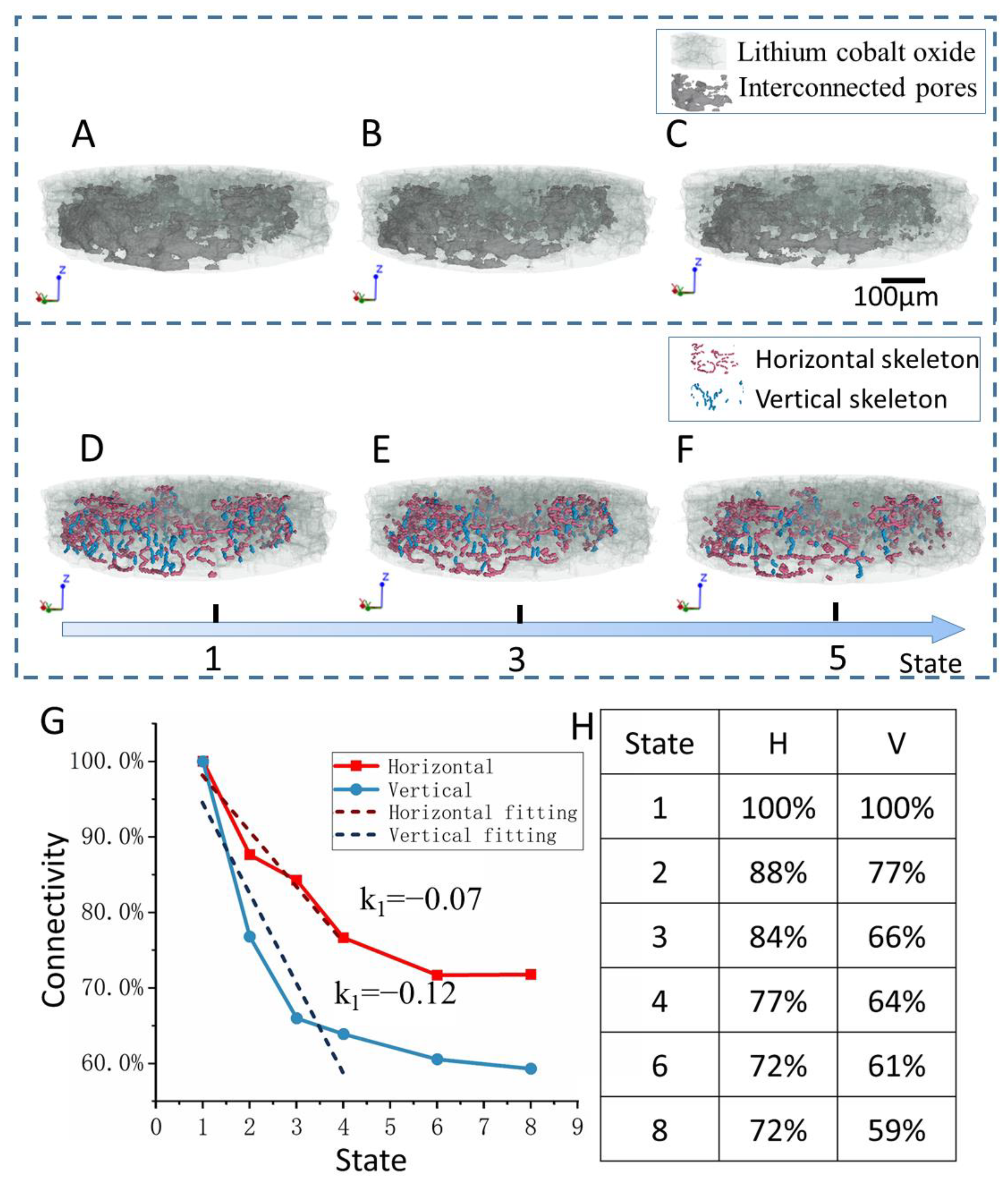
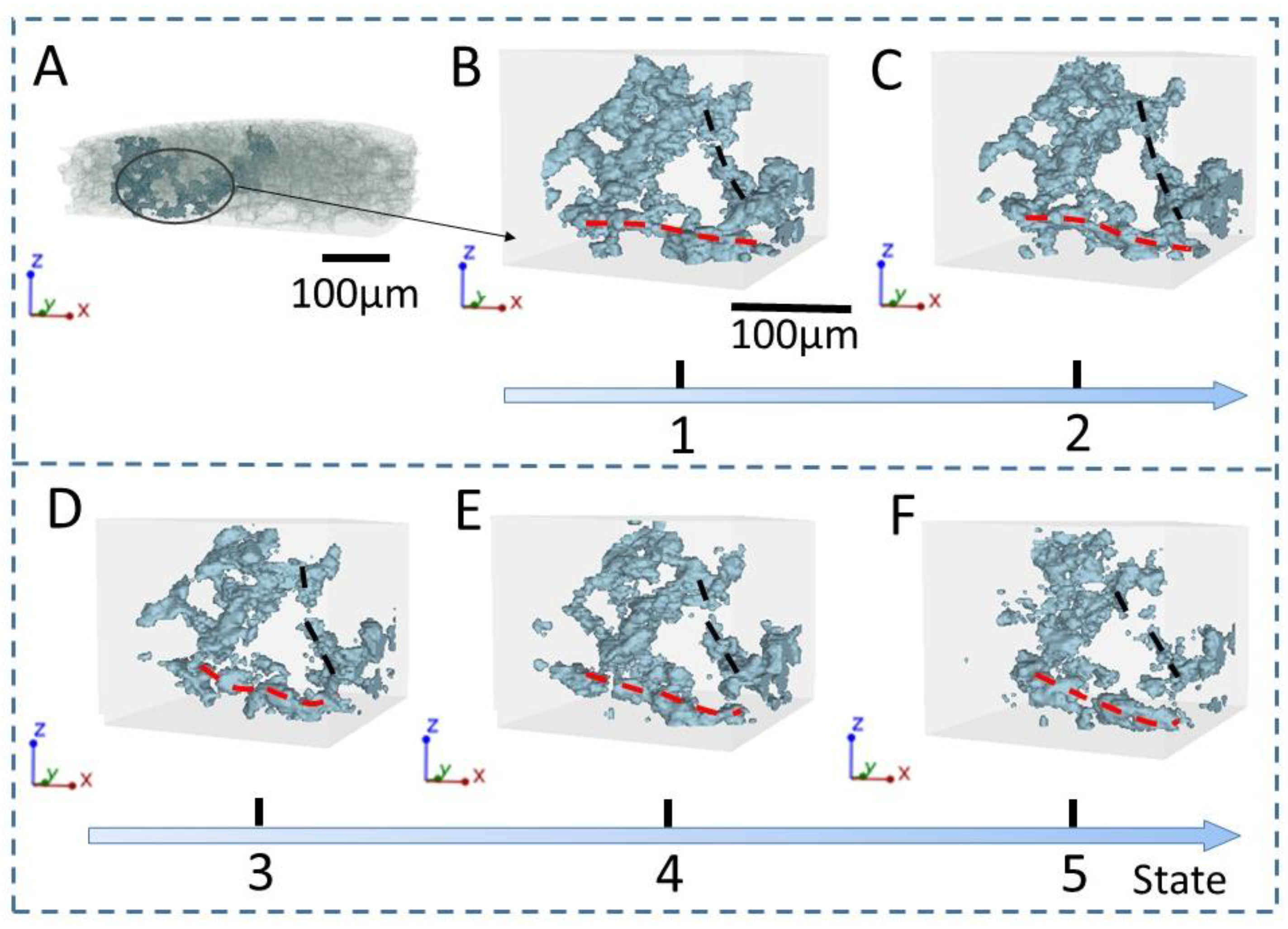
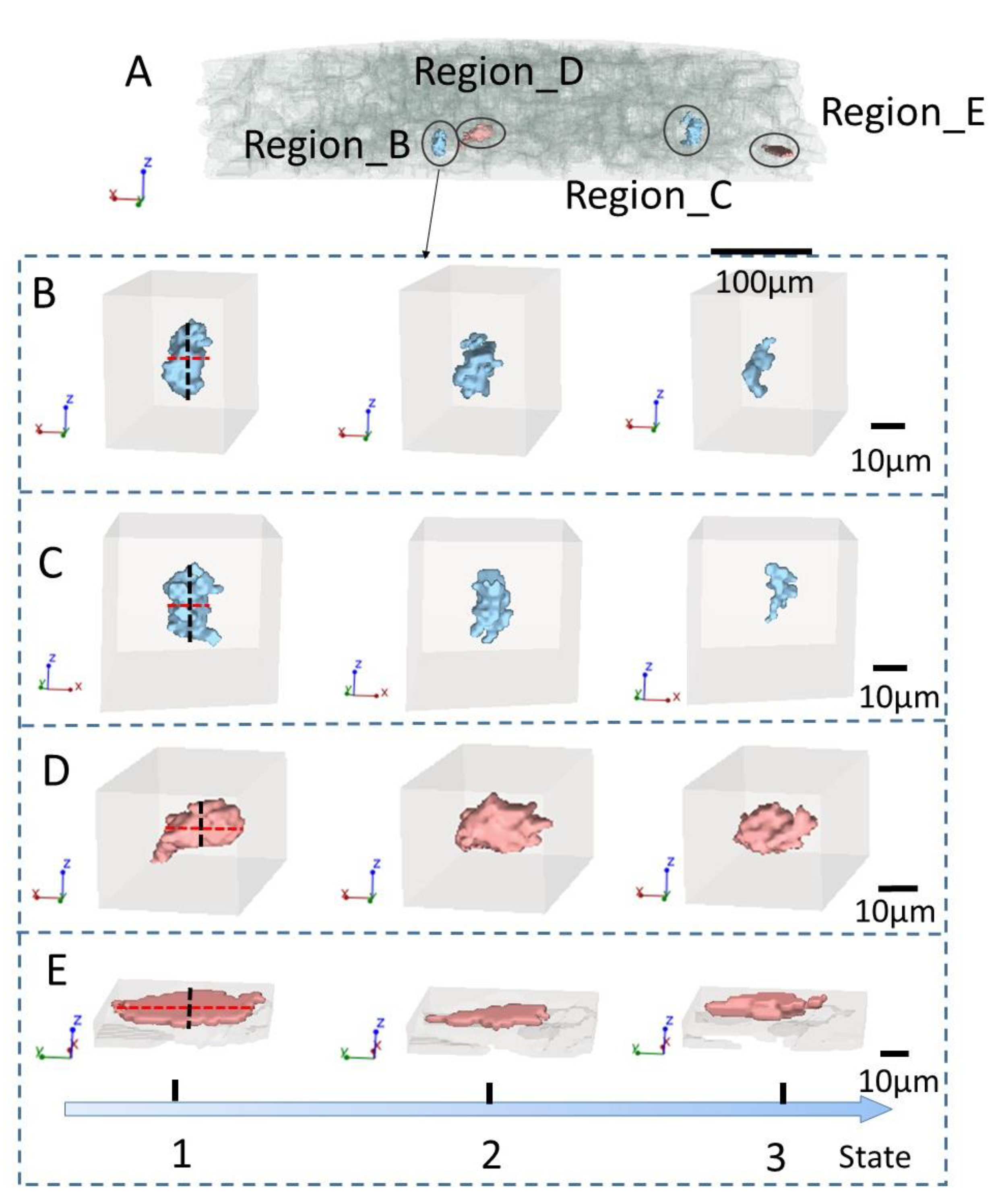
3. Results and Discussion

As is well known, interconnected pores within electrodes serve as crucial channels for ion transport in electrolytes [25,26]. Through synchrotron radiation experiments, we have obtained three-dimensional evolution images of electrode samples during microwave sintering and quantitatively characterized the evolution of interconnected pores. Figure 3A–C depict the three-dimensional images of samples at the initial, intermediate, and final stages of sintering, where light-colored regions represent electrode materials and dark-colored regions represent interconnected pores. The size of the interconnected pores is large in the initial state, connecting the top and bottom of the electrode. As the sintering experiment progressed, by the intermediate state, the necks between particles gradually grew, leading to a reduction in pore size. The interconnected pores began to fracture, with some transforming into isolated pores, thereby reducing connectivity. As the process advanced from the intermediate state to the end of sintering, the isolated pores rapidly shrank, causing the interconnected pore regions to disappear locally. Some of the interconnected pores transformed into new isolated pores, further diminishing connectivity. Through topological refinement, the interconnected pore structure was skeletonized to extract the pore centerlines. This method effectively preserved the topological structure of the pore space and visually represented the characteristics of pore connectivity [27]. Figure 3D–F display the three-dimensional skeleton images of interconnected pores at the initial, intermediate, and final stages of sintering. In these figures, the red parts represent the horizontal skeleton, and the blue parts represent the vertical skeleton. Horizontal skeletons are well preserved during the sintering process, while vertical skeletons tend to disappear more.
Through image observations, we noted that the horizontal connectivity of the electrode is better maintained than the vertical connectivity. Therefore, we further quantified connectivity by measuring the lengths of horizontal and vertical skeletons. Figure 3G shows the evolution curves of horizontal and vertical connectivity over time, where the red curve represents horizontal connectivity and the blue curve represents vertical connectivity. State 1 indicates the initial stage, and state 8 indicates the final stage, with each state separated by 668 ms. Connectivity decreases sharply in the early stages of sintering and gradually slows down in the later stages. For the first four stages, performing linear regression shows that the slope of the fitted line for horizontal connectivity is −0.07, while for vertical connectivity, it is −0.12. Table H presents numerical values depicting the temporal evolution of horizontal and vertical connectivity. Horizontal connectivity decreases to 77% after four states and gradually declines to 72% by the final state, whereas vertical connectivity decreases to 77% by the second state and further drops to 59% by the final state. It can be seen that the rate of decrease in vertical connectivity during the early stages of sintering and its final decrease proportion are both higher than those of horizontal connectivity. Through the observation of three-dimensional evolution images of interconnected pores and statistical analysis of connectivity in both orientations, we conclude that microwave sintering can selectively preserve the orientation of pore connectivity.
To further illustrate the directional evolution features, we enlarged a local area of interconnected pores. From Figure 4A, a specific region was selected and magnified, and Figure 4B–F show the evolution images of this area. Figure 4B represents the initial state of this region, where light-colored parts depict lithium cobalt oxide electrode material and green parts indicate interconnected pores. Red dashed lines and black dashed lines, respectively, mark a pair of interconnected pore regions with similar morphology and volume in the horizontal and vertical orientations. As sintering progressed, the pore volume in Figure 4C gradually reduced in this area. In Figure 4D,E, regions with smaller pore volume in the vertical direction began to disappear, resulting in a decrease in vertical connectivity. Figure 4F shows the final state of this region, where the volume of vertically interconnected pores has significantly decreased compared to the initial state, leading to a rapid decline in vertical connectivity, while the volume of horizontally interconnected pores has only slightly reduced. Observing the evolution of this local area reveals that vertical pores disappear more during the evolution process, while horizontal pores maintain their overall structure, thus preserving better horizontal connectivity.
According to classical electromagnetic theory, for a standard circular pore, the electric field intensity at the interface between the pore and the material is given by [27] as follows:
E r R , θ = 3 ϵ 2 2 ϵ 1 + ϵ 2 E cos θ
E θ R , θ = 3 ϵ 1 2 ϵ 1 + ϵ 2 E sin θ
where E r is the axial component of the interface electric field intensity, E θ is the tangential component of the interface electric field intensity, θ = 0 ° is the direction of the electric field, R is the pore radius, E is the intensity of the external electric field, ϵ 1 and ϵ 2 are the relative permittivities of the material and air, respectively. For lithium cobalt oxide particles, ϵ 1 = 96 , and for air, ϵ 2 = 1 . The electric field intensity is primarily determined by the tangential component E θ , which increases with increasing θ ; θ = 90° corresponds to the direction of maximum electric field intensity. The electromagnetic loss in lithium cobalt oxide particles promotes the growth of sintering necks, which is the cause of pore evolution. The spatial heterogeneity of the electric field results in the directional evolution of the pores. To elucidate the mechanism of pore evolution, further research is needed on the influence of electromagnetic fields on the neck growth during sintering.
The growth of sintering necks depends on the interaction between the microwave field and the particles [28,29]. To study the evolution mechanism, we established a particle–electric field model and employed numerical simulation methods [30]. Figure 5A illustrates the particle–electric field model, where four lithium cobalt oxide particles are initially placed. Sintering necks (S-1, S-2, S-3, S-4) between the particles were labeled: S-1 and S-2 were parallel to the vertical electric field direction, while S-3 and S-4 were perpendicular.
Microwave sintering of lithium cobalt oxide particles relies on the electromagnetic power dissipation occurring within the material, where the absorbed electromagnetic power is converted into thermal energy for sintering the material [31]. To obtain the electromagnetic power distribution on the particle surfaces, finite element simulations were conducted. A cubic domain of 1 mm × 1 mm × 1 mm was created under the same experimental conditions: vertical electric field strength of 25,000 V/m at a microwave frequency of 2.45 GHz. The electromagnetic field was treated as a static electric field to solve for the instantaneous electromagnetic power loss distribution. The lithium cobalt oxide particles, with relative permittivity ϵ = 96 relative permeability μ = 1 , and conductivity σ = 2 × 10 3 . The air in other regions had ϵ = 1 , μ = 1 , and σ = 0 .
Figure 5B shows the electromagnetic power loss on the particle surfaces in the microwave field, with the maximum occurring at the neck regions. As sintering time increases, sintering necks between particles begin to form and grow. Influenced by the electric field direction, perpendicular sintering necks (S-3 and S-4) exhibit electromagnetic focusing, converting electromagnetic power loss into heat and significantly promoting the growth of perpendicular sintering necks.
The greater growth of perpendicular sintering necks compared to parallel ones leads to the predominantly horizontal contraction of pores. Figure 5C illustrates the evolution of vertical pores, where the gray parts represent particles and the blue parts represent vertical pores. The smaller horizontal dimensions of vertical pores result in rapid volume reduction due to horizontal contraction. Figure 5D illustrates the evolution of horizontal pores, with gray parts representing particles and red parts representing horizontal pores. Horizontal pores have larger dimensions in the horizontal plane, and their volume decreases to a certain extent due to horizontal contraction. Horizontal contraction has a significantly greater impact on the volume reduction in vertical pores than on horizontal pores.
Through simulation, it was observed that the maximum electromagnetic power loss consistently occurs at the two sintering necks perpendicular to the electric field direction. Horizontal sintering necks grow significantly, while vertical pores disappear rapidly.
The anisotropic growth rate of sintering necks during the same sintering time is the reason for the directional evolution of pores. To further demonstrate the directional evolution differences in pore evolution, four local regions were selected, and the characteristics of isolated small pores in different directions were analyzed.
Figure 6A illustrates a three-dimensional distribution of isolated pores in the electrode. Figure 6B–E illustrate the evolution images of local isolated pores: B and C represent vertical pores, while D and E represent horizontal pores. The major axis of vertical pores is indicated by black dashed lines, directed within the vertical plane, and the minor axis by red dashed lines, directed within the horizontal plane. The minor axis undergoes rapid contraction during evolution, leading to a rapid decrease in the volume of vertical pores. The major axis of horizontal pores lies within the horizontal plane, and the minor axis within the vertical plane. The major axis undergoes contraction during evolution but does not result in a significant reduction in pore volume. Significant growth of horizontal sintering necks causes rapid contraction of vertical pores, while horizontal pores exhibit slow contraction and maintain good connectivity in the horizontal direction.
On the basis of in situ SR-CT, the directional evolution of pores in lithium cobalt oxide was captured, and the evolution mechanism was discussed. Vertical pores shrink rapidly, while horizontal pores are better preserved. The electric field intensity is greater at the sintering neck in the direction perpendicular to the electric field, which accelerates material diffusion and leads to faster vertical pore shrinkage. As Figure 7 shows, under the influence of an electric field during microwave sintering, the pores in lithium cobalt oxide would become more and more directional, which is benefit for the trade-off between the high density and high porosity of sintered electrodes. Hence, this research could provide a potential method for fabricating normal-size electrodes with both high density and high ion transport efficiency, suitable for use in batteries.

4. Conclusions

In conclusion, we used microwave sintering to process lithium cobalt oxide materials and observed the directional evolution of pores using SR-CT. Microwave radiation induces electromagnetic losses on the particle surfaces, converting electromagnetic energy into thermal energy and leading to material diffusion between particles, which forms sintering necks and reduces pore volume. SR-CT, with its high flux and resolution (1.8125 μm/pixel) and short inter-CT state interval (167 ms), revealed that pore shrinkage is directional: vertical pores shrink rapidly, while horizontal pores are better preserved. Simulations indicate that the electric field distribution on the particle surfaces affects pore evolution, with increased field strength perpendicular to the electric field accelerating material diffusion and resulting in faster vertical pore shrinkage. This suggests that the electric field influences pore orientation, offering a potential method for fabricating electrodes with vertical microchannels.

Author Contributions

L.W.: Validation, Investigation; Y.X.: Investigation; Y.L.: Validation, Investigation; X.W.: Editing. All authors have read and agreed to the published version of the manuscript.

Funding

This research was supported by the National Natural Science Foundation of China (no. 12027901 and no. 12041202) and the Synchrotron Radiation Joint Fund of the University of Science and Technology of China (KY2090000059 and KY2090000054).

Data Availability Statement

Please be informed that restrictions apply to the datasets presented in this article as they are part of ongoing studies which have not yet been published. To ensure the integrity and priority of these upcoming publications, we are unable to publicly release these specific datasets at this time. Requests for access to the datasets should be directed to the corresponding author. Each request will be considered on a case-by-case basis after evaluating all relevant factors, including the status of related research works and any applicable restrictions.

Acknowledgments

The authors would like to thank Zhongliang Li and Guohao Du for their help with the experiment at the BL09b beam line of SSRF.

Conflicts of Interest

The authors declare no competing financial interests.

References

  1. Eng, A.Y.S.; Soni, C.B.; Lum, Y.; Khoo, E.; Yao, Z.; Vineeth, S.K.; Kumar, V.; Lu, J.; Johnson, C.S.; Wolverton, C.; et al. Theory-Guided Experimental Design in Battery Materials Research. Sci. Adv. 2022, 8, eabm2422. [Google Scholar] [CrossRef] [PubMed]
  2. Kumar, D.; Rizwan, M.; Panwar, A.K. Advanced Intelligent Approach for State of Charge Estimation of Lithium-Ion Battery. Energy Sources Part A Recovery Util. Environ. Eff. 2023, 45, 10661–10681. [Google Scholar] [CrossRef]
  3. Nuhu, B.A.; Adun, H.; Bamisile, O.; Mukhtar, M. Ti-Fe-Si/C Composites as Anode Materials for High Energy Li-Ion Batteries. Energy Sources Part A Recovery Util. Environ. Eff. 2022, 44, 5154–5171. [Google Scholar] [CrossRef]
  4. Wu, J.; Zhang, X.; Ju, Z.; Wang, L.; Hui, Z.; Mayilvahanan, K.; Takeuchi, K.J.; Marschilok, A.C.; West, A.C.; Takeuchi, E.S.; et al. From Fundamental Understanding to Engineering Design of High-Performance Thick Electrodes for Scalable Energy-Storage Systems. Adv. Mater. 2021, 33, 2101275. [Google Scholar] [CrossRef]
  5. Arnot, D.J.; Mayilvahanan, K.S.; Hui, Z.; Takeuchi, K.J.; Marschilok, A.C.; Bock, D.C.; Wang, L.; West, A.C.; Takeuchi, E.S. Thick Electrode Design for Facile Electron and Ion Transport: Architectures, Advanced Characterization, and Modeling. Acc. Mater. Res. 2022, 3, 472–483. [Google Scholar] [CrossRef]
  6. Yang, X.; Doyle-Davis, K.; Gao, X.; Sun, X. Recent Progress and Perspectives on Designing High-Performance Thick Electrodes for All-Solid-State Lithium Batteries. eTransportation 2022, 11, 100152. [Google Scholar] [CrossRef]
  7. Chen, Y.; Zhao, B.; Yang, Y.; Cao, A. Toward High-Areal-Capacity Electrodes for Lithium and Sodium Ion Batteries. Adv. Energy Mater. 2022, 12, 2201834. [Google Scholar] [CrossRef]
  8. You, J.; Deng, L.; Wang, W.; Li, Y.; Meng, S.; Cao, Y.; Zhang, B.; Xu, Z. Cyclosulfate Additive Inhibits Li Dendrite Disorder Growth to Achieve Stable Cycles of Li Metal Battery. Energy Sources Part A Recovery Util. Environ. Eff. 2024, 46, 13125–13135. [Google Scholar] [CrossRef]
  9. Jeong, H.; Lim, S.-J.; Chakravarthy, S.; Kim, K.H.; Lee, J.; Heo, J.S.; Park, H. Three-Dimensional Cathode with Periodically Aligned Microchannels for Improving Volumetric Energy Density of Lithium-Ion Batteries. J. Power Sources 2020, 451, 227764. [Google Scholar] [CrossRef]
  10. Tong, H.; Liu, J.; Qiao, Y.; Amardeep, A.; Song, X. Microstructure and Electrochemistry Performance of the Composite Electrode Prepared by Spark Plasma Sintering. J. Eur. Ceram. Soc. 2023, 43, 419–427. [Google Scholar] [CrossRef]
  11. Elango, R.; Nadeina, A.; Cadiou, F.; De Andrade, V.; Demortière, A.; Morcrette, M.; Seznec, V. Impact of Electrode Porosity Architecture on Electrochemical Performances of 1 Mm-Thick LiFePO4 Binder-Free Li-Ion Electrodes Fabricated by Spark Plasma Sintering. J. Power Sources 2021, 488, 229402. [Google Scholar] [CrossRef]
  12. Kim, K.H.; Jeong, H.; Lee, H.C.; Shon, J.K.; Park, J.; Park, H.-Y. Stable Cycling of High-Density Three-Dimensional Sintered LiCoO2 Plate Cathodes. J. Power Sources 2022, 551, 232223. [Google Scholar] [CrossRef]
  13. Huang, F.; Zhao, Q.; Yang, J.; Zhang, H.; Huo, W.; Xu, F. Spherical Mesophase Soft Carbon Materials with Micro-Nano Composite Structure and Their Applications in Lithium-Ion Batteries. Energy Sources Part A Recovery Util. Environ. Eff. 2018, 40, 1675–1680. [Google Scholar] [CrossRef]
  14. Li, S.; Wang, K.; Zhang, G.; Li, S.; Xu, Y.; Zhang, X.; Zhang, X.; Zheng, S.; Sun, X.; Ma, Y. Fast Charging Anode Materials for Lithium-Ion Batteries: Current Status and Perspectives. Adv. Funct. Mater. 2022, 32, 2200796. [Google Scholar] [CrossRef]
  15. Ma, J.; Sung, J.; Hong, J.; Chae, S.; Kim, N.; Choi, S.-H.; Nam, G.; Son, Y.; Kim, S.Y.; Ko, M.; et al. Towards Maximized Volumetric Capacity via Pore-Coordinated Design for Large-Volume-Change Lithium-Ion Battery Anodes. Nat. Commun. 2019, 10, 475. [Google Scholar] [CrossRef]
  16. Lu, L.-L.; Lu, Y.-Y.; Zhu, Z.-X.; Shao, J.-X.; Yao, H.-B.; Wang, S.; Zhang, T.-W.; Ni, Y.; Wang, X.-X.; Yu, S.-H. Extremely Fast-Charging Lithium Ion Battery Enabled by Dual-Gradient Structure Design. Sci. Adv. 2022, 8, eabm6624. [Google Scholar] [CrossRef]
  17. Cao, Q.; Gao, Y.; Pu, J.; Zhao, X.; Wang, Y.; Chen, J.; Guan, C. Gradient Design of Imprinted Anode for Stable Zn-Ion Batteries. Nat. Commun. 2023, 14, 641. [Google Scholar] [CrossRef]
  18. Mypati, O.; Pawar, R.M.A.; Sengupta, I.; Mani Sharma, V.; Majumder, S.B.; Pal, S.K.; Srirangam, P. The Synthesis of Novel Porous Graphene Anodes for Fast Charging and Improved Electrochemical Performance for Lithium-Ion Batteries. Energy Sources Part A Recovery Util. Environ. Eff. 2022, 44, 4349–4363. [Google Scholar] [CrossRef]
  19. Ju, Z.; King, S.T.; Xu, X.; Zhang, X.; Raigama, K.U.; Takeuchi, K.J.; Marschilok, A.C.; Wang, L.; Takeuchi, E.S.; Yu, G. Vertically Assembled Nanosheet Networks for High-Density Thick Battery Electrodes. Proc. Natl. Acad. Sci. USA 2022, 119, e2212777119. [Google Scholar] [CrossRef]
  20. Ju, Z.; Checko, S.; Xu, X.; Calderon, J.; Raigama, K.U.; Takeuchi, K.J.; Marschilok, A.C.; Takeuchi, E.S.; Yu, G. Densified Vertically Lamellar Electrode Architectures for Compact Energy Storage. Proc. Natl. Acad. Sci. USA 2023, 120, e2308009120. [Google Scholar] [CrossRef]
  21. Chen, J.; Chen, M.; Chen, H.; Yang, M.; Han, X.; Ma, D.; Zhang, P.; Wong, C.-P. Wood-Inspired Anisotropic Hydrogel Electrolyte with Large Modulus and Low Tortuosity Realizing Durable Dendrite-Free Zinc-Ion Batteries. Proc. Natl. Acad. Sci. USA 2024, 121, e2322944121. [Google Scholar] [CrossRef] [PubMed]
  22. Willemink, M.J.; de Jong, P.A.; Leiner, T.; de Heer, L.M.; Nievelstein, R.A.J.; Budde, R.P.J.; Schilham, A.M.R. Iterative Reconstruction Techniques for Computed Tomography Part 1: Technical Principles. Eur. Radiol. 2013, 23, 1623–1631. [Google Scholar] [CrossRef] [PubMed]
  23. Geyer, L.L.; Schoepf, U.J.; Meinel, F.G.; Nance, J.W.; Bastarrika, G.; Leipsic, J.A.; Paul, N.S.; Rengo, M.; Laghi, A.; De Cecco, C.N. State of the Art: Iterative CT Reconstruction Techniques. Radiology 2015, 276, 339–357. [Google Scholar] [CrossRef] [PubMed]
  24. Lee, T.C.; Kashyap, R.L.; Chu, C.N. Building Skeleton Models via 3-D Medial Surface Axis Thinning Algorithms. CVGIP Graph. Models Image Process. 1994, 56, 462–478. [Google Scholar] [CrossRef]
  25. Chen, X. 3D-Printed Hierarchical Pillar Array Electrodes for High-Performance Semi-Artificial Photosynthesis. Nat. Mater. 2022, 21, 811–818. [Google Scholar] [CrossRef]
  26. Yeon, J.S.; Gupta, N.; Bhattacharya, P.; Park, H.S. A New Era of Integrative Ice Frozen Assembly into Multiscale Architecturing of Energy Materials. Adv. Funct. Mater. 2022, 32, 2112509. [Google Scholar] [CrossRef]
  27. Lacava, F. Classical Electrodynamics: From Image Charges to the Photon Mass and Magnetic Monopoles; Undergraduate Lecture Notes in Physics; Springer International Publishing: Cham, Switzerland, 2022. [Google Scholar] [CrossRef]
  28. Masin, B.; Ashok, K.; Sreemoolanadhan, H. Microwave Hybrid Sintering of 0.95(Mg0.95Zn0.05)TiO3-0.05CaTiO3 Ceramics and Its Microwave Dielectric Properties. J. Eur. Ceram. Soc. 2022, 42, 4974–4979. [Google Scholar] [CrossRef]
  29. Ramarao, S.D.; Kiran, S.R.; Murthy, V.R.K. Structural, Morphological and Microwave Dielectric Studies on Microwave Sintered ZnWO4 Ceramic Compounds. Ceram. Int. 2023, 49, 23075–23081. [Google Scholar] [CrossRef]
  30. Wang, L.; Shen, L.; Li, Y.; Wang, Y.; Xiao, Y.; Zhang, X.; Xu, F.; Hu, X. In Situ SR-CT Experimental Study on the Directional Sintering of High-Temperature Superconductor YBCO Materials in the Microwave Fields. Acta Metall. Sin. (Engl. Lett.) 2022, 35, 67–77. [Google Scholar] [CrossRef]
  31. Qin, M.; Zhang, L.; Wu, H. Dielectric Loss Mechanism in Electromagnetic Wave Absorbing Materials. Adv. Sci. 2022, 9, 2105553. [Google Scholar] [CrossRef]
Figure 1. Microwave sintering system.
Crystals 15 00368 g001
Figure 2. Extraction of interconnected pore structures: (A) lithium cobalt oxide and all pores; (B) lithium cobalt oxide with extracted interconnected pores; (C) pore skeleton; (D) pore skeleton classification; (E) horizontal skeleton; (F) vertical skeleton.
Crystals 15 00368 g002
Figure 3. Structural evolution of interconnected pores: (A) 3D image of the initial state of pores; (B) 3D image of the intermediate state of pores; (C) 3D image of the final state of pores; (D) 3D image of the initial state of pore skeletons; (E) 3D image of the intermediate state of pore skeletons; (F) 3D image of the final state of pore skeletons; (G) Diagram of connectivity evolution; (H) Table of connectivity evolution.
Crystals 15 00368 g003
Figure 4. Local connectivity pore evolution image. (A) Local pore magnification image; (B) 3D image of State 1; (C) 3D image of State 2; (D) 3D image of State 3; (E) 3D image of State 4; (F) 3D image of State 5.
Crystals 15 00368 g004
Figure 5. Particle–field model. (A) Schematic diagram of particles and electric field; (B) Simulation results of electromagnetic loss in particles; (C) Schematic diagram of longitudinal pore evolution; (D) Schematic diagram of transverse pore evolution.
Crystals 15 00368 g005
Figure 6. Local evolution image of isolated pores: (A) local pore magnification image; (B) 3D evolution diagram of horizontal pore 1; (C) 3D evolution diagram of horizontal pore 2; (D) 3D evolution diagram of vertical pore 1; (E) 3D evolution diagram of vertical pore 2.
Crystals 15 00368 g006
Figure 7. A potential method for fabricating electrodes with directional pores for both high density and high ion transport efficiency: (A) electromagnetic field distribution diagram of the microwave cavity; (B) schematic diagram of pores before sintering; (C) schematic diagram of pores after sintering.
Crystals 15 00368 g007
Disclaimer/Publisher’s Note: The statements, opinions and data contained in all publications are solely those of the individual author(s) and contributor(s) and not of MDPI and/or the editor(s). MDPI and/or the editor(s) disclaim responsibility for any injury to people or property resulting from any ideas, methods, instructions or products referred to in the content.

