Article

Revisiting the Relation Between Magnesium and Heterogeneous Nucleation of Spheroidal Graphite

Chair of Metallurgy, Institut für Technologien der Metalle, Universität Duisburg Essen, Friedrich-Ebert-Str. 12, 47119 Duisburg, Germany
*
Author to whom correspondence should be addressed.
Crystals 2025, 15(4), 347; https://doi.org/10.3390/cryst15040347
Submission received: 20 March 2025 / Revised: 1 April 2025 / Accepted: 2 April 2025 / Published: 7 April 2025

Abstract

:
This research presents an innovative method for revisiting heterogeneous nucleation in the formation of spheroidal graphite during the production of ductile cast iron. This study incorporates controlled melting at a temperature of 1200 °C, followed by a rapid cooling process, to increase the likelihood of revealing and subsequently observing the graphite nuclei. Given the slow dissolution rate of spheroidal graphite, this sequence produces finer graphite nodules associated with residual graphite that has partially dissolved. Furthermore, the investigation explores diverse configurations of treatment agents to reexamine their effects during the nucleation of nodular graphite. The findings revealed that the graphite nucleus comprised oxides, sulfides, carbides, nitrides, and carbo-nitrides, confirming the reliability of the approach considered in this study. Additionally, the research highlights the crucial role of magnesium in the nucleation of nodular graphite structures. Several mechanisms are expected to be used in conjunction with distinct treatment agents. It involves segregation and solubility dynamics, desulfurization and deoxidation, and inclusions as heterogeneous nucleation sites.

1. Introduction

Ductile iron (SGI) has emerged as an exceptionally versatile material and has thus received increased attention for its diverse application in various technical sectors. Notably, according to the World Foundry Organization (WFO) [1], the production volume of SGI over the last five decades has experienced more notable and pronounced growth than gray cast iron (LGI) has. However, despite its reliability and continuous advancements since its discovery in 1938 [2], the discourse surrounding the nucleation and growth process of spheroidal graphite has not reached a consensus. Following the subsequent patents in 1949 in which molten iron was treated with cerium [3] or magnesium [4], this lack of clarity regarding the establishment of SGI signifies the necessity for comprehensive and additional elucidations.
Considering the two major forms of nucleation, the homogeneous nucleation of graphite during the solidification of cast iron is intriguingly debatable. In general, although significant undercooling (200–230 °C) [5,6,7] might be needed, some results suggest that the availability of crystalline carbon (Cn cluster) could provide an effective nucleus. The idea was based on the formation of a carbon-rich region given the state of molten iron as a colloidal system [6,7], as indicated by increasing viscosity [8] along with elevated carbon content. Furthermore, it was experimentally observed that using graphite-bearing charge/return [9,10] and carbide [11,12] materials during the preparation and treatment of molten iron could enhance the formation of carbon-rich zones and increase the nucleation potential. Hence, a nonmetallic core is not always necessary for graphite nucleation, as supported in [13,14,15].
Conversely, given the industrial case of molten iron, which is never a pure Fe-C-Si alloy but instead contains a particular concentration of impurities, prevailing arguments propose that the heterogeneous mechanism is preferable. In this context, at least two primary proposals are involved in the heterogeneous nucleation of nodular graphite. The first idea argues that graphite nucleates at the interface of magnesium bubbles and molten iron [16,17]. Another perspective suggests that it occurs at the interface of nonmetallic inclusions and molten metal [18,19]. The latter view has garnered more significant support from researchers upon the use of diverse examination methods. However, it is crucial to note that despite the massive number of samples investigated by Alonso et al. [20], there is no definitive assertion that all graphite has a nonmetallic core, underscoring the complexity of the nucleation process.
Considering heterogeneous nucleation involving inclusions, numerous studies have revealed that oxides [21,22], sulfides [23,24], carbides [25,26], nitrides [27,28], or carbo-nitrides [29,30] can function as nuclei for nodular graphite, where their compounds can encompass single- [31,32], double- [33,34], or triple-stage [35] nucleation. Furthermore, the chemical composition of molten metal related to the treatment process could also influence the chemical composition of the nuclei [36]. Nonetheless, given the diverse potential configurations of nuclei resulting from the production sequences applied to molten ductile iron, the necessity of these configurations during the nucleation and growth of nodular graphite remains unclear. Despite extensive research on the role of nonmetallic nuclei in graphite formation, no definitive conclusion has been reached regarding whether a specific composition, form, or configuration is absolutely necessary to facilitate both nucleation and subsequent growth. Additionally, there is no consensus on the influence of magnesium during the nucleation process, as conflicting perspectives persist regarding its affinity for oxygen and sulfur, as well as its precise role in the precipitation of graphite.
Therefore, this study aims to revisit and identify various nonmetallic particles found as potential nonmetallic cores of nodular graphite structures and to reexamine the interplay between various treatment agents on graphite precipitation in cast iron, including the role of magnesium addition in nodular graphite nucleation. To achieve this, two alternative methodologies are introduced that enhance the investigation of graphite structures and their associated nonmetallic nuclei. Those two methods are currently overlooked; however, the forthcoming results indicate their efficiency and benefits for both laboratory experiments and industrial applications. The first method is a partial dissolution technique proposed to enhance the likelihood of directly accessing and analyzing the core of graphite nodules, thereby facilitating the observation of their nonmetallic nuclei. Meanwhile, the second approach offers a novel, small-scale method for evaluating the nucleation potential of various treatment agents, facilitating a more efficient and accelerated research process while ensuring reliable results.

2. Materials and Methods

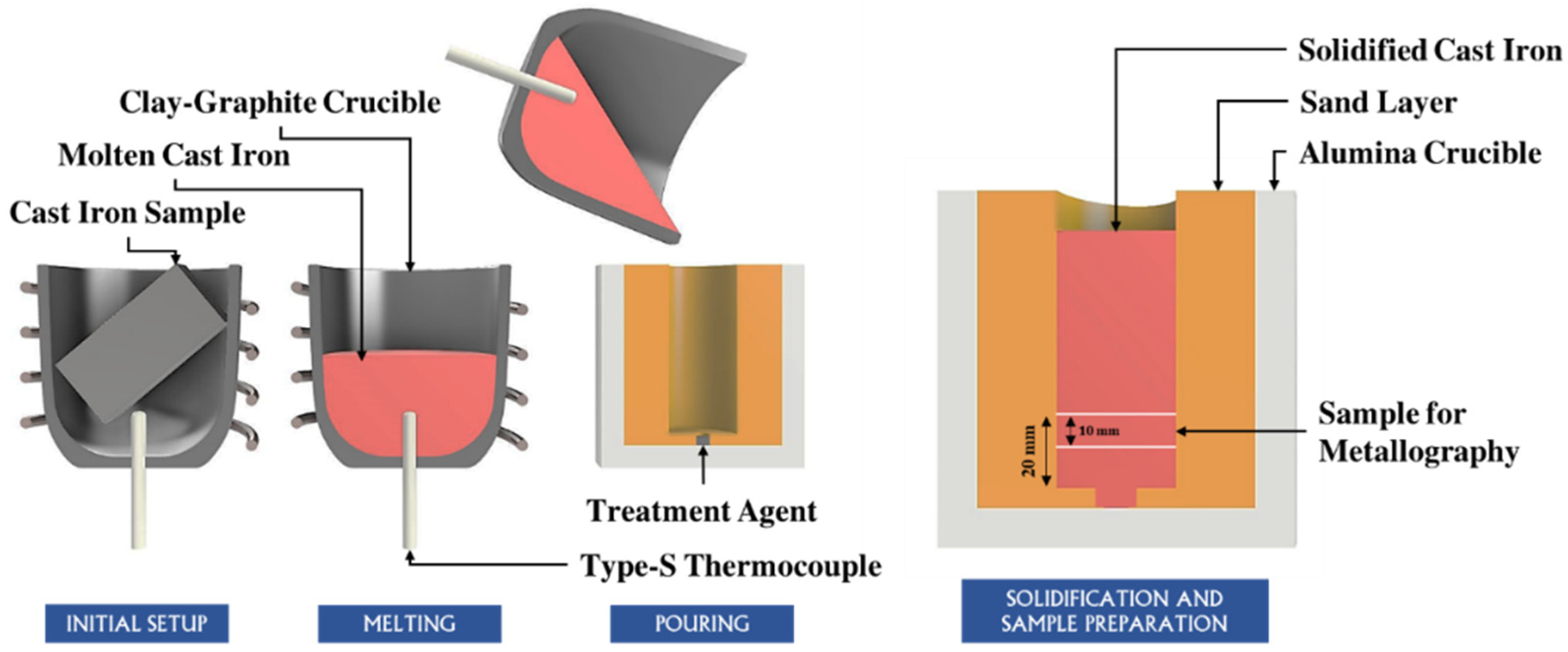
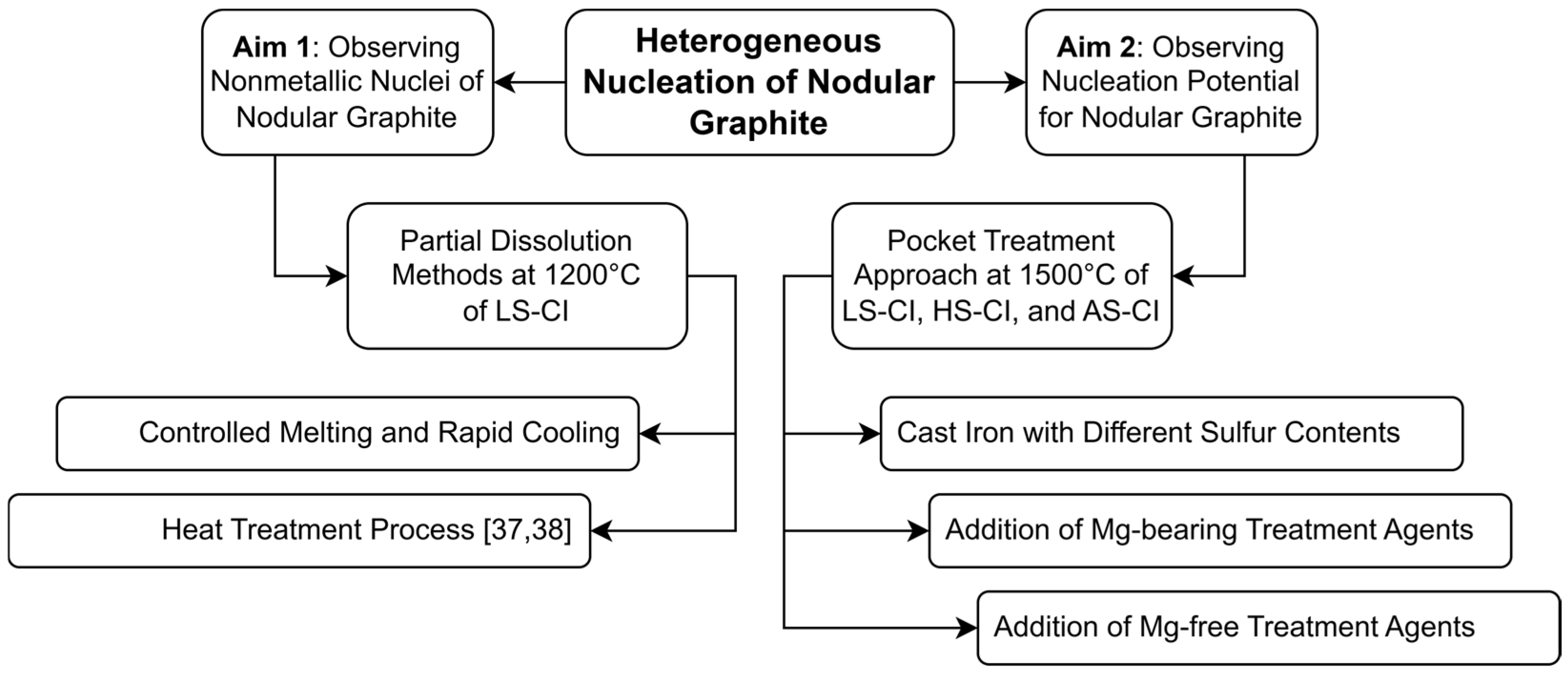
Following the objectives of this study, two distinct experimental setups were implemented, as indicated in Figure 1. The first approach employed controlled melting trials, in which the partial dissolution of the pre-existing nodular graphite structure in SGI return material was induced to enhance the detection of graphite nuclei. On the other hand, the second approach is the pocket treatment trials. This approach involved preparing base iron by re-melting different cast iron samples and casting them into a prepared sand-layered alumina-based crucible containing predetermined amounts of various treatment agents. Both methodologies are discussed in detail in the subsequent sections.

2.1. Observation of the Nuclei of Nodular Graphite (Controlled Melting Trials)

As part of the preliminary investigation, a reassessment of the nodular graphite nuclei was carried out. Cast iron samples coded as LS-CI (low sulfur cast iron) were employed in this section, representing an SGI return material with chemical composition as listed in Table 1.
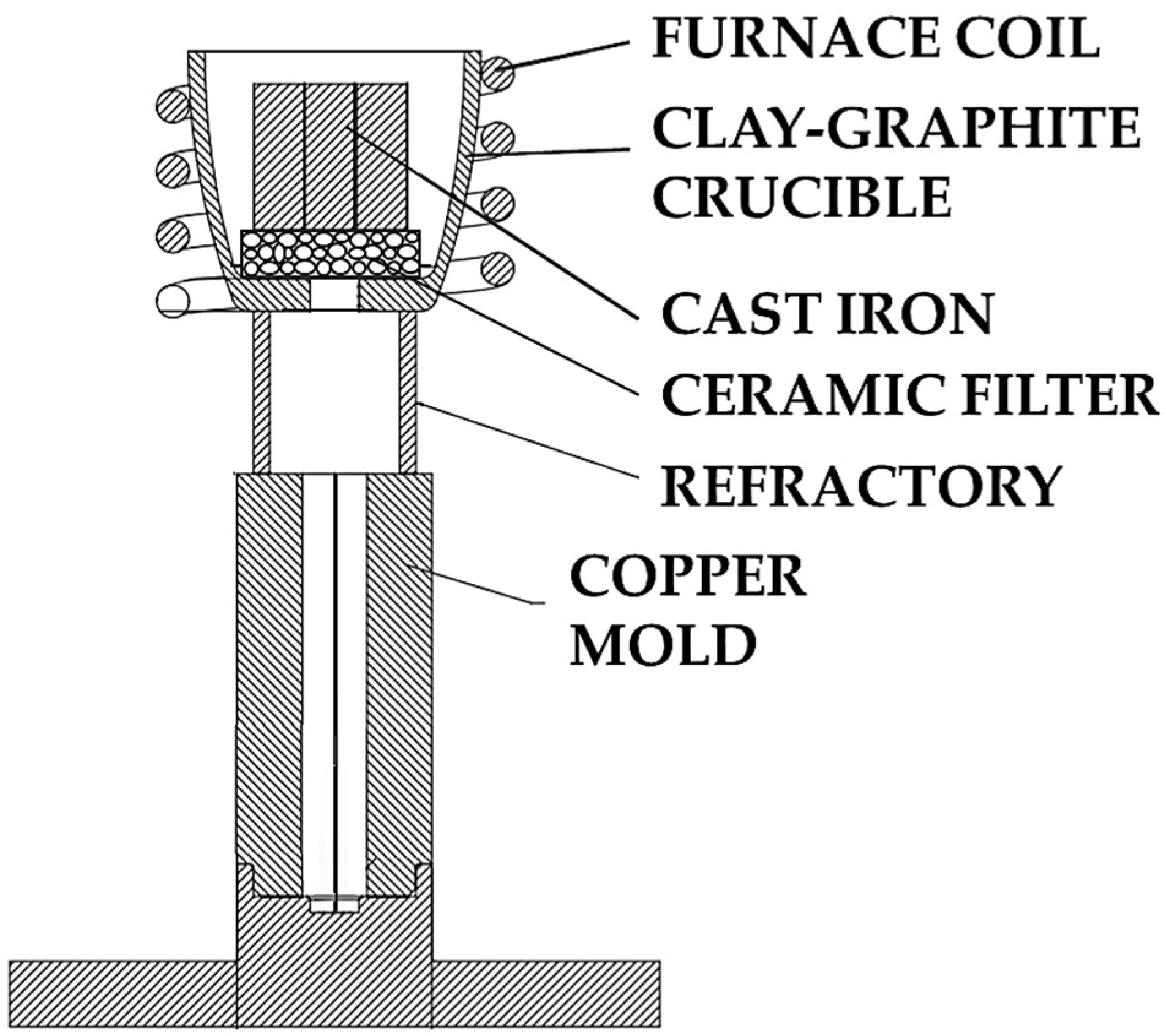
The detailed construction of the experiment in controlled melting trials is provided in Figure 2. Based on the illustration, the trial involved around 100 g of LS-CI, which was melted in a clay-graphite crucible using an induction furnace in atmospheric conditions. This crucible was equipped with a base opening yet secured by a ceramic filter. As the temperature increased and the liquid phase began to form, molten LS-CI flowed through the filter channels and dripped into a copper mold located beneath the melting system. Controlled by a type-S thermocouple, the temperature was maintained at approximately 1200 °C to retain a significant number of residual nodular graphite. The reason for the selection of this controlled temperature to produce smaller nodular graphite due to incomplete or partial dissolution is provided in a separate dedicated report [37,38]. Subsequently, the produced samples (re-solidified cast iron in a copper mold) were prepared for metallographic analysis using a light microscope coupled with a scanning electron microscope with X-ray dispersive spectroscopy (SEM/EDS). Residual graphites from the previous exploration in [37,38] were also incorporated as supplementary samples investigated in the present study to increase the number of observed graphite nuclei.

2.2. Effect of Treatment Agents on Graphite Nucleation (Pocket Treatment Trials)

In addition to LS-CI, this section incorporates two additional cast iron samples to explore the effects of different treatment agents on graphite nucleation. The second cast iron sample (desulfurized cast iron or HS-CI) is produced using a cupola furnace and subjected to varying degrees of lime-based desulfurization, which explains the range of its sulfur content provided in Table 1. Any further details about the implementation and applicability of this alternative desulfurization operation are provided in dedicated reports [39,40]. Furthermore, the third sample (alloyed cast iron or AS-CI) is a prepared cast iron sample created by re-melting ARMCO pure iron, FeSi75, and graphite in proportional quantities to achieve a chemical composition comparable to SGI. Together with LS-CI and HS-CI, the chemical composition of AS-CI is also available in Table 1.
As illustrated in Figure 3, for one pocket treatment trial, approximately 400 g of the cast iron sample was melted in a clay-graphite crucible using an induction furnace in atmospheric conditions. Immediately after reaching the designated pouring temperature, the molten cast iron was swiftly poured into a cylindrical cast cavity (diameter of 25 mm) in a double-layered mold comprising a sand-layered alumina crucible. In this instance, the explored melting-pouring temperature was 1500 °C. In addition, FeSiMg6, FeSi75, FeSi-CeLa, SiC, Ca, CaSi, CaC2, Mg-AlSn, and NiMg15 were utilized as treatment agents positioned at the bottom of the mold to address the effects of various variables on nodular graphite nucleation, including different sulfur content and magnesium addition.
It is worth noting that the procedure employed in this experiment differs from conventional production on SGI. In contrast to the standard industrial practice of magnesium treatment and the inoculation process of the base molten iron, the process sequence considered in the present experiment only directly treats the base molten iron with the designated treatment agents mentioned previously in a pocket treatment. Despite the contrast in the treatment process compared to the conventional procedure, the forthcoming results indicate that the formation of observable nodular graphite can still be achieved. Hence, after the complete solidification, metallography observations of the graphite structures were conducted on the sectioned sample from the solidified cast iron, as also graphically indicated in Figure 3.

3. Experimental Results

3.1. Chemical Composition of the Nonmetallic Nuclei in the Residual Nodular Graphite Structures After Controlled Melting Trials

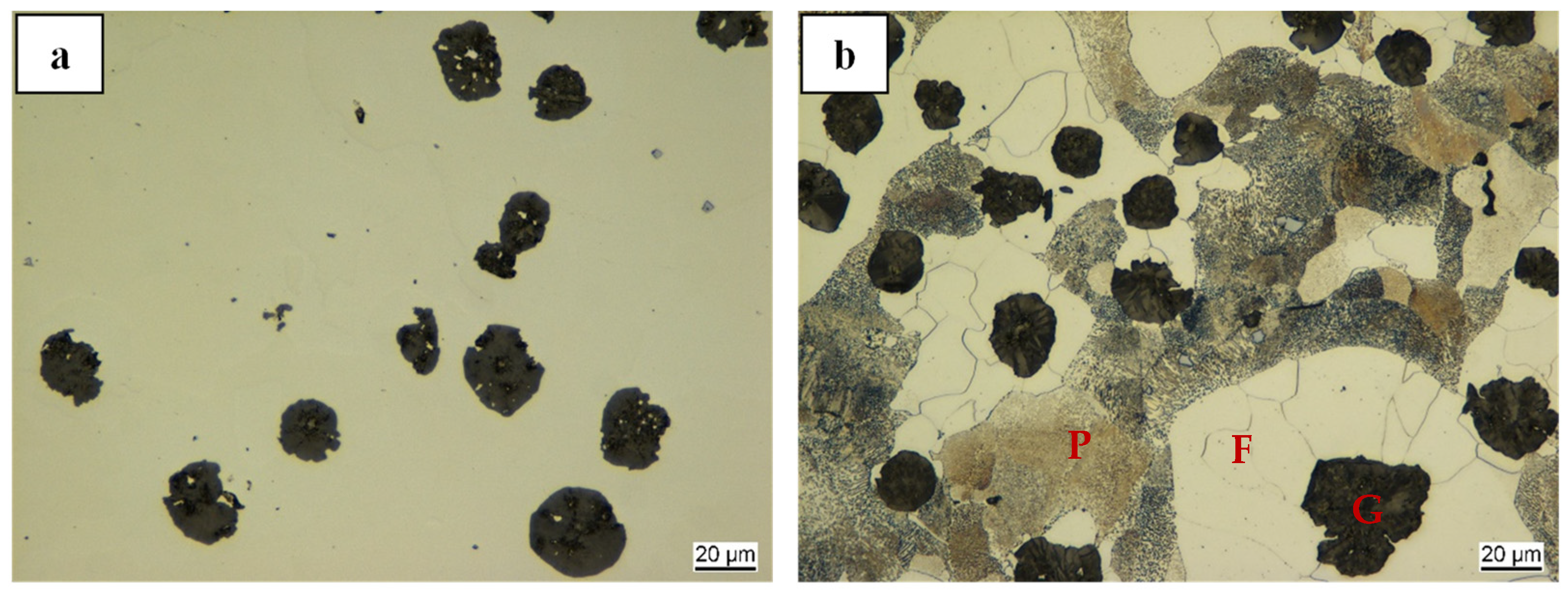
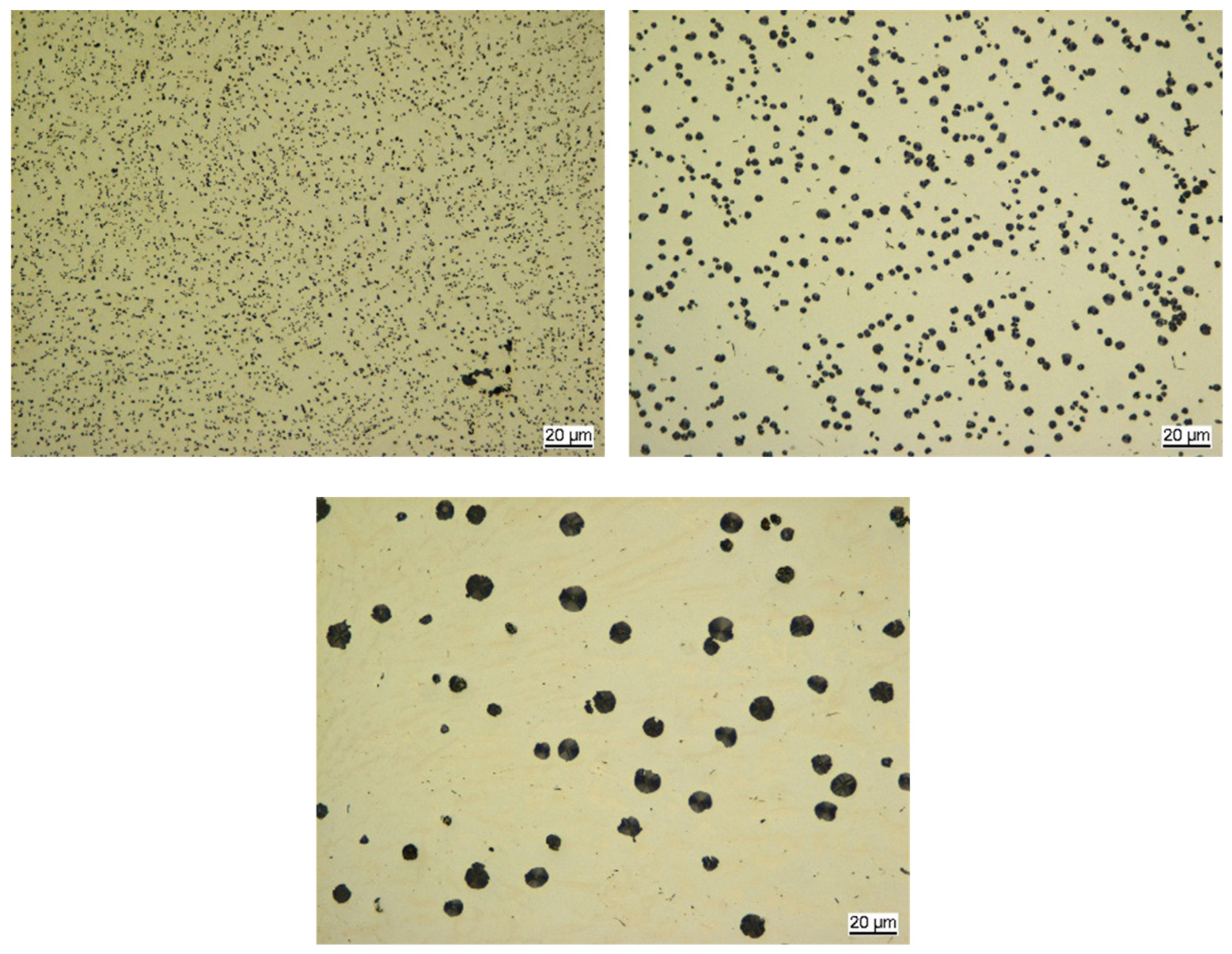
As documented in Figure 4, the as-received LS-CI (before the melting process) exhibited a spheroidal graphite structure with an average diameter of approximately 20 µm surrounded by an iron matrix comprising a pearlite-ferrite configuration. Following the controlled melting process at 1200 °C, a reduction in nodule size was observed, as depicted in Figure 5. Their dimensions range from 10 µm to fine nodules less than 500 nm in diameter. Nonetheless, because of specific technical considerations, graphite larger than 5 µm was preferred, already reaching a substantial 75% reduction in diameter. One reason is the considered investigation approach, which starts with cursory elemental mapping before delving into the chemical analysis of the nuclei.
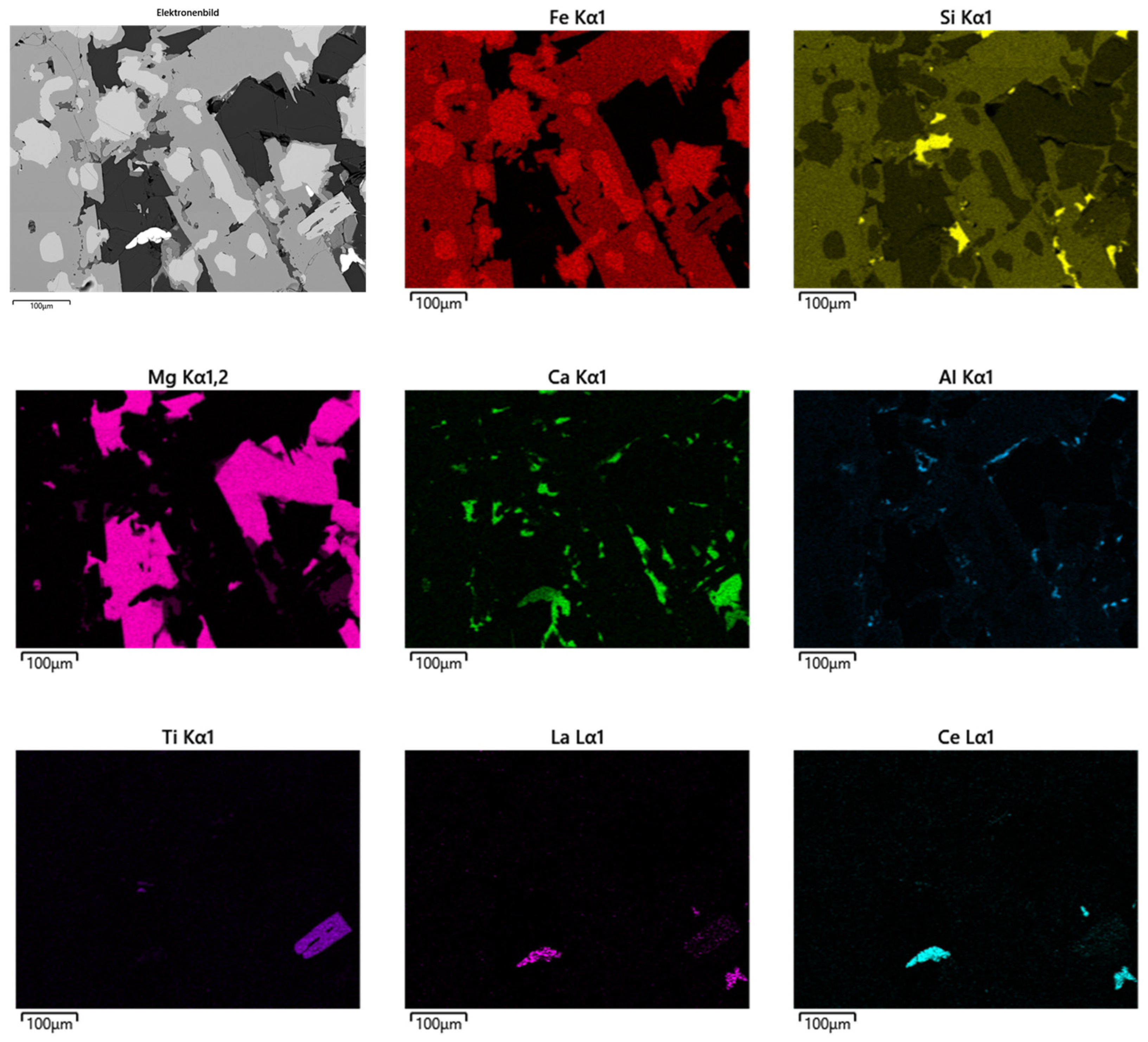
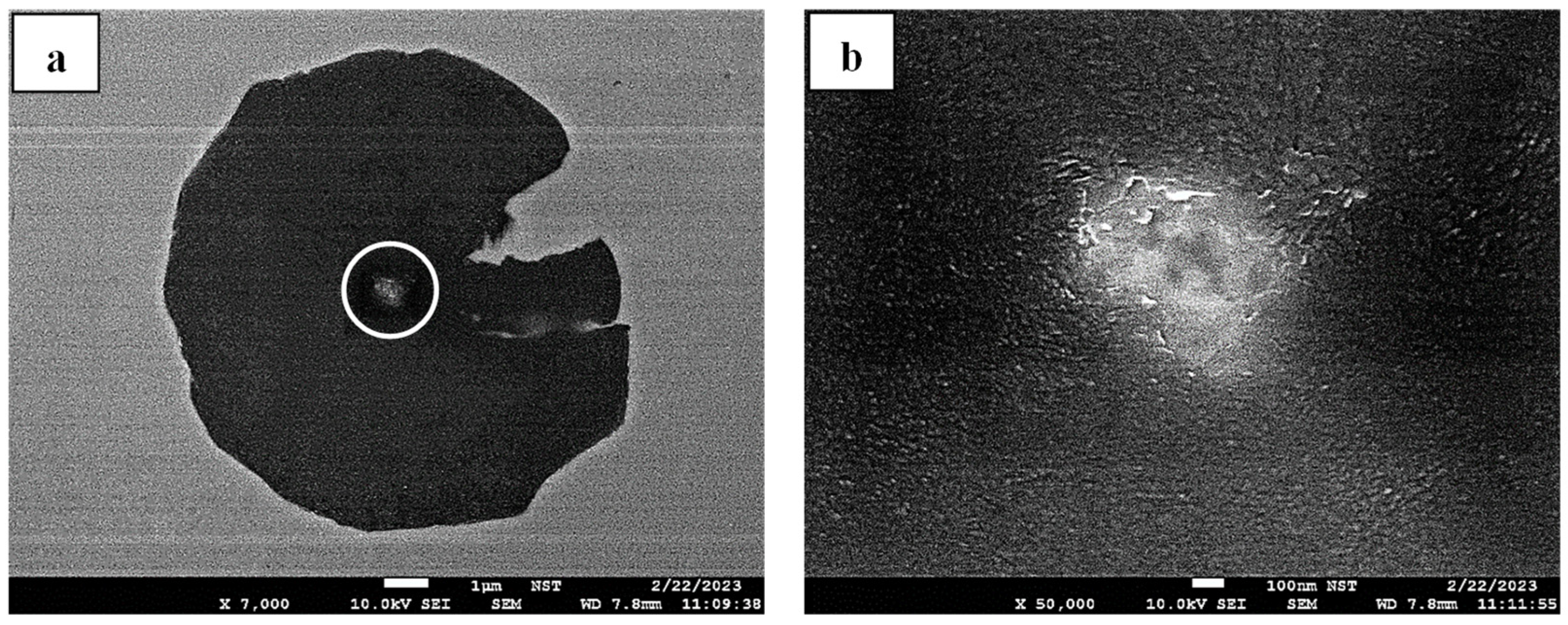
Several nonmetallic inclusions have been exposed based on the preparatory observation of partially dissolved residual nodular graphite. According to the chemical analysis in Table 2 corresponding to the measurement points in Figure 6, the inclusions consisted of oxides, sulfides, or (carbo-) nitrides. Moreover, in addition to Fe, C, and Si, which are the primary alloying elements of LS-CI, other components could also be detected in the inclusion. These elements, including Mg, Al, Ca, P, Ce, and La, are available as commercial treatment agents for casting ductile cast iron (FeSiMg6), as shown in Figure 7. Based on this initial positive result, subsequent data enrichment of graphite nuclei from controlled melting trials and graphite dissolution studies was conducted. Accordingly, the inclusions can be categorized into oxy-sulfide, carbo-nitride, or complex-compound configurations.
The chemical analysis of various oxy-sulfide configurations found within or affixed to residual graphite is summarized in Table 3. As depicted in Figure 8, a well-preserved spheroid containing a predominant Mg-O system has been identified, coupled with a minor detection of Si and Al. A comparable system can also be implicated in concurrently identifying increasing sulfur concentrations, as documented in Figure 9. Furthermore, a higher sulfur content can also be detected in the center of the distorted graphite, as Ca, Ce, and La were measured in the respective structures, as provided in Figure 10a. In another case, a certain level of Ti can also be perceived following a notable amount of N, as substantiated in Figure 10b.
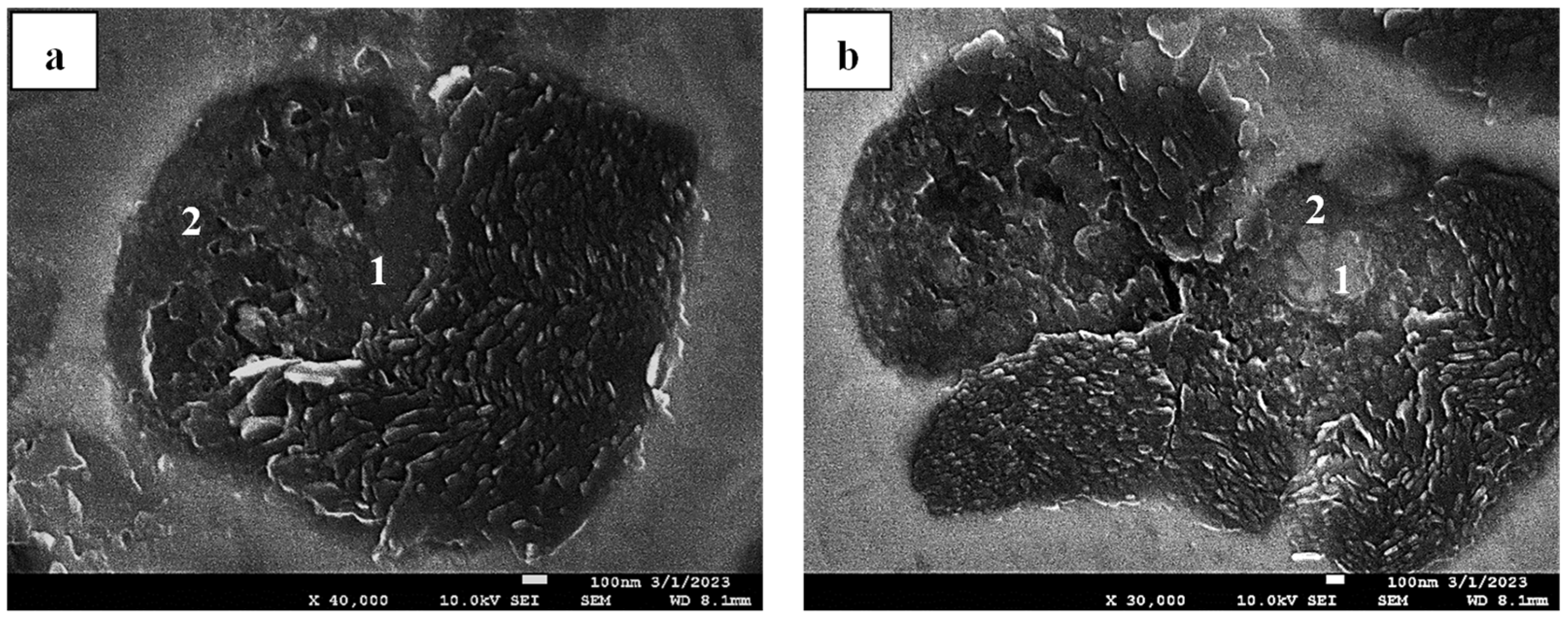
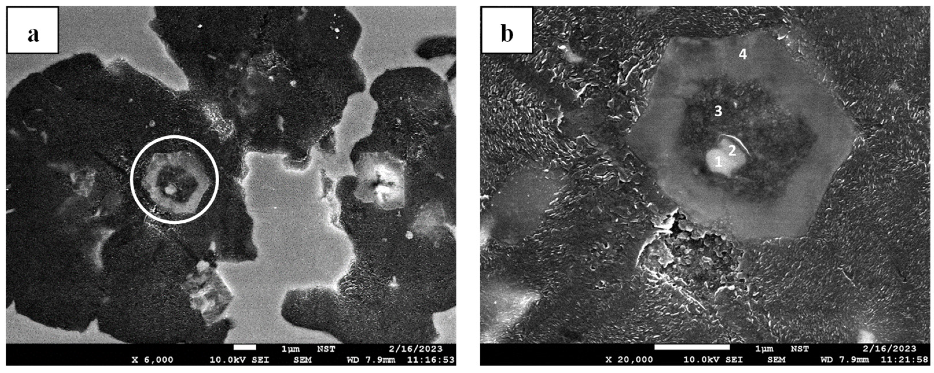
The establishment of carbides and nitrides as inclusions found in residual nodular graphite was also detected in simple configurations or complex compounds, as they coexisted with the oxy-sulfide system. Table 4 indicates a possible Si-C system to construct a nucleus in the residual graphite nodule documented in Figure 11a. Furthermore, a simple nitride compound is also substantiated in Figure 11b, which is also the most frequent configuration found in the boundary of this study. As detailed in Figure 12, this nitride structure located in the center of the graphite nodule was attached to the residual graphite structure, and it was expected to contain an Mg-Si-N configuration with a minor amount of Al, as listed in Table 4.
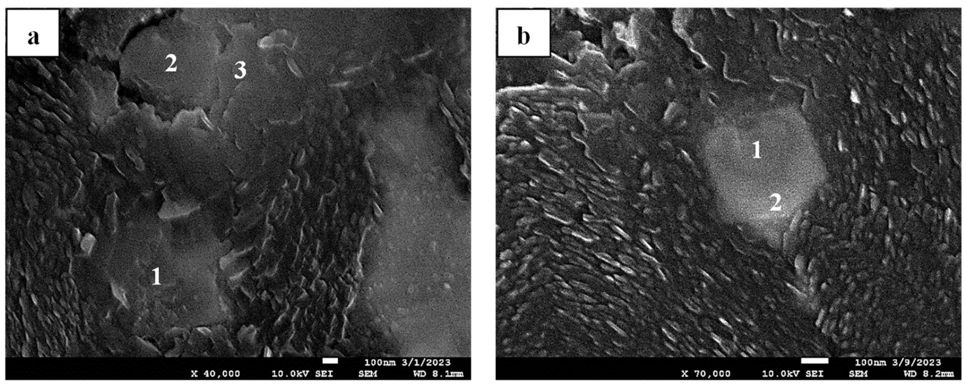
In addition to simple carbide and nitride inclusions, complex compounds were also detected within the residual graphite. Table 5 indicated that the oxy-sulfide could coexist with the carbo-nitride configuration. As representatively documented in Figure 13, a staged nuclei system is substantiated. Chemical analysis revealed that an oxide with a Ti-N configuration forms the core, where an oxy-sulfide and Mg-Si-N system acts as a covering layer before the graphite structure grows on it.
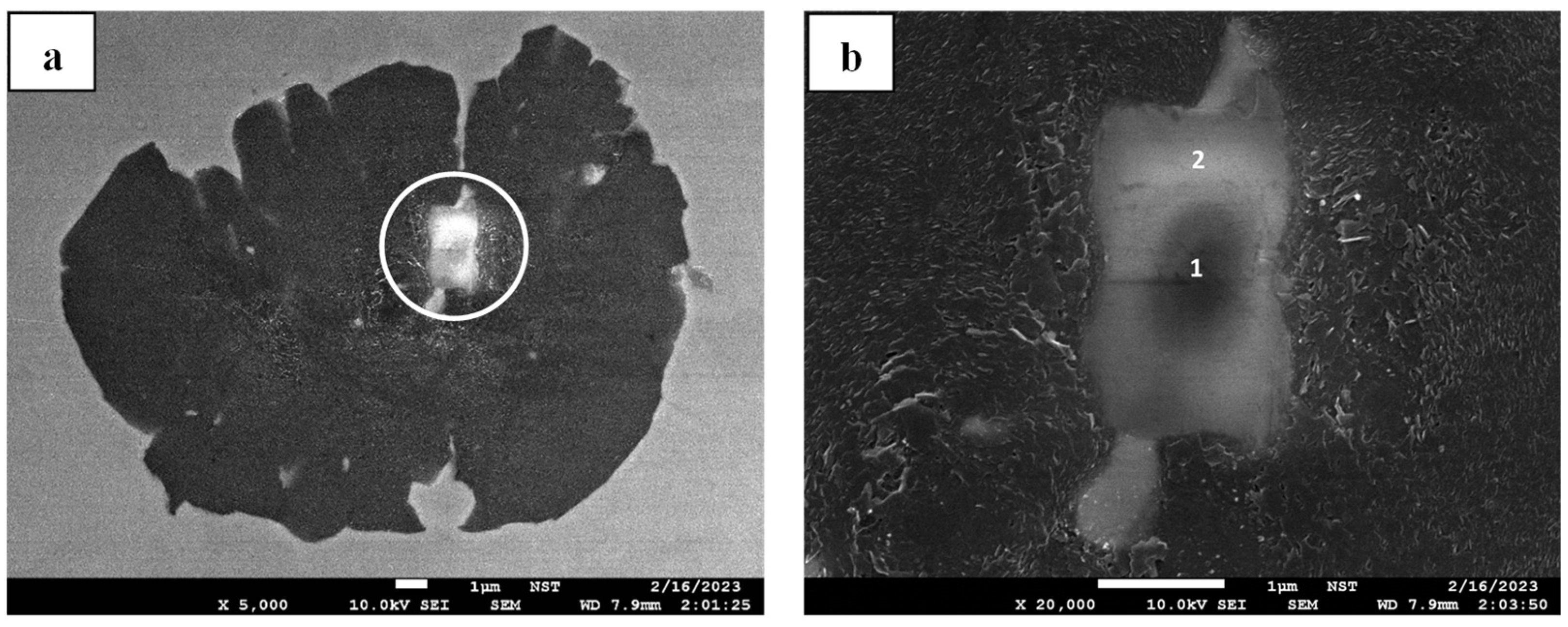
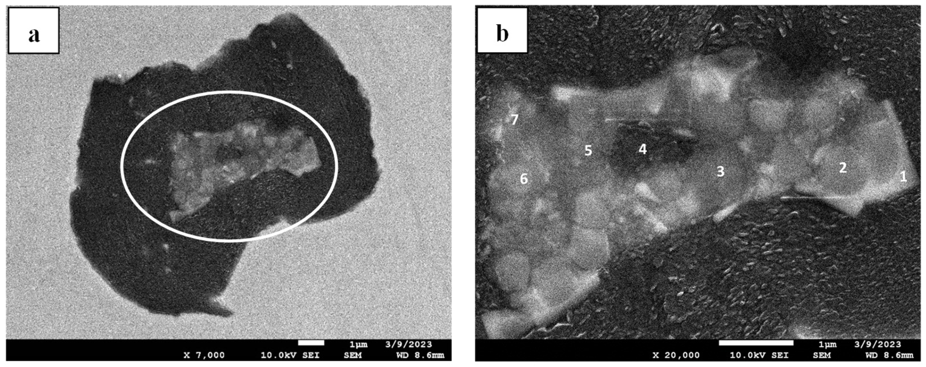
In another case documented in Figure 14, a complex compounding system is proposed based on several oxy-sulfide and carbo-nitride systems. Listed in Table 5, considering the measurement point, especially Figure 14b 1 and 2, a trace of possible oxides and oxy-sulfides involving Mg could be expected to coexist with nitride and carbo-nitride associated with Ti. Furthermore, an increasing proportion of the oxy-sulfide system can be observed as the measurement point moves toward the center (Figure 14b 3 to 6). Particularly in Figure 14b 5 and 7, notable concentrations of Al and Ti are measured, indicating the possible complex formation of Al-O and Ti-C, respectively. Notably, it is worth mentioning that the graphite structure grows on those inclusions regardless of their different chemical compositions.

3.2. Effect of the Various Treatment Agents During Pocket Treatment Trials on the Nucleation of the Graphite Structure

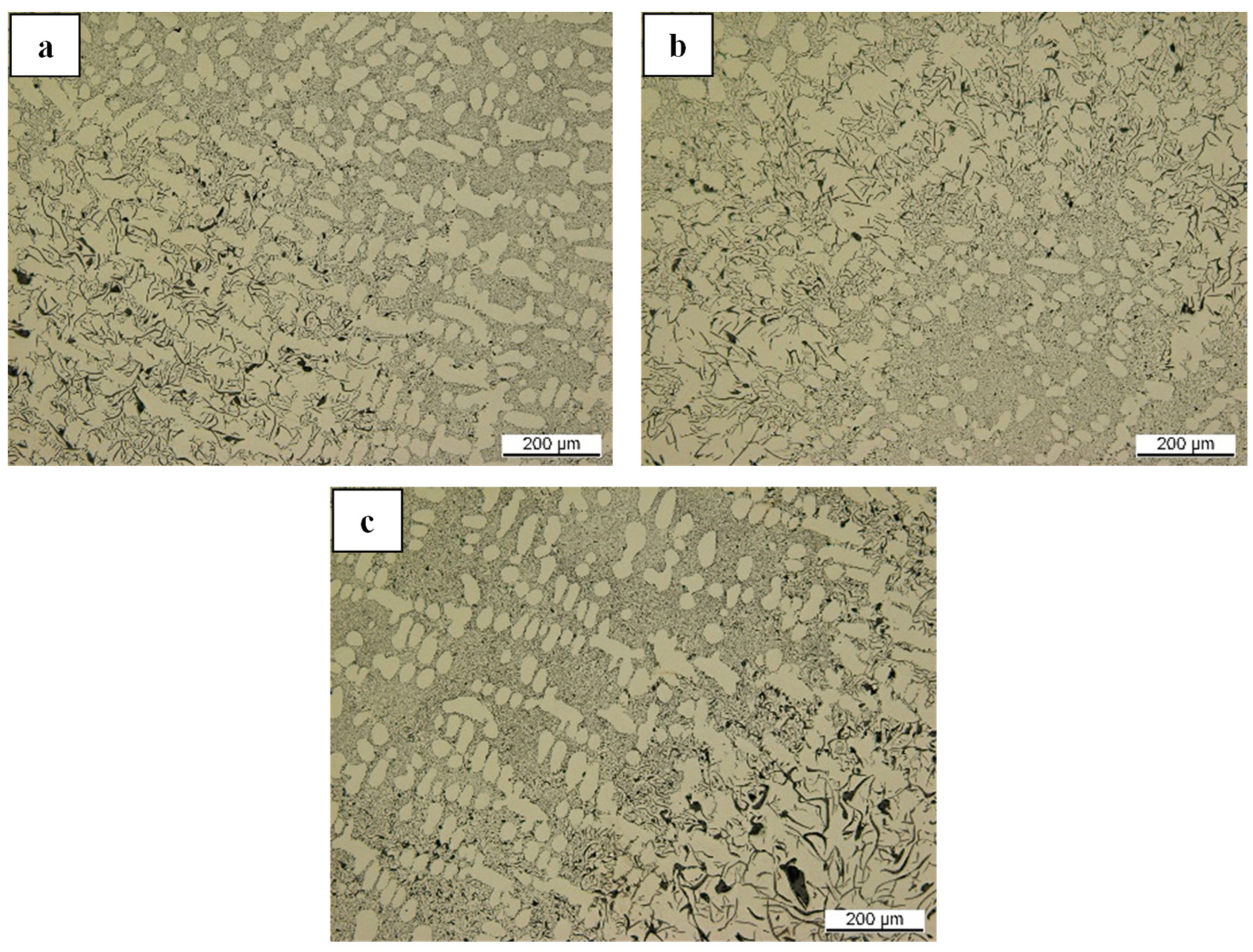
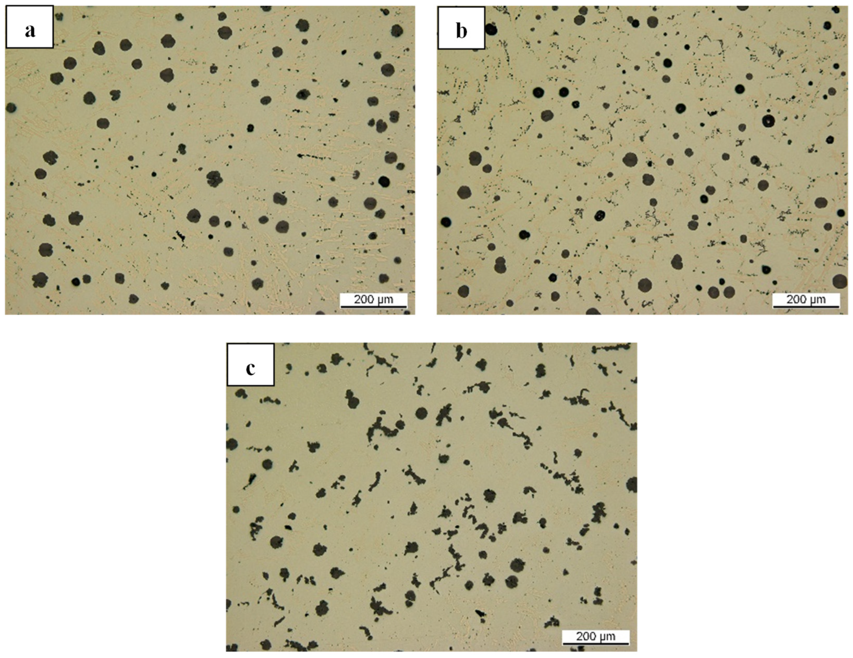
Following the setup illustrated in Figure 3, an initial identification was carried out where no treatment agent was placed on the base of the crucible. As shown in Figure 15, all the samples melted and cast at 1500 °C have no nodular graphite structure and instead exhibit predominantly undercooled lamellar graphite. This reference is essential considering the original structure and characteristics of LS-CI, HS-CI, and AS-CI.
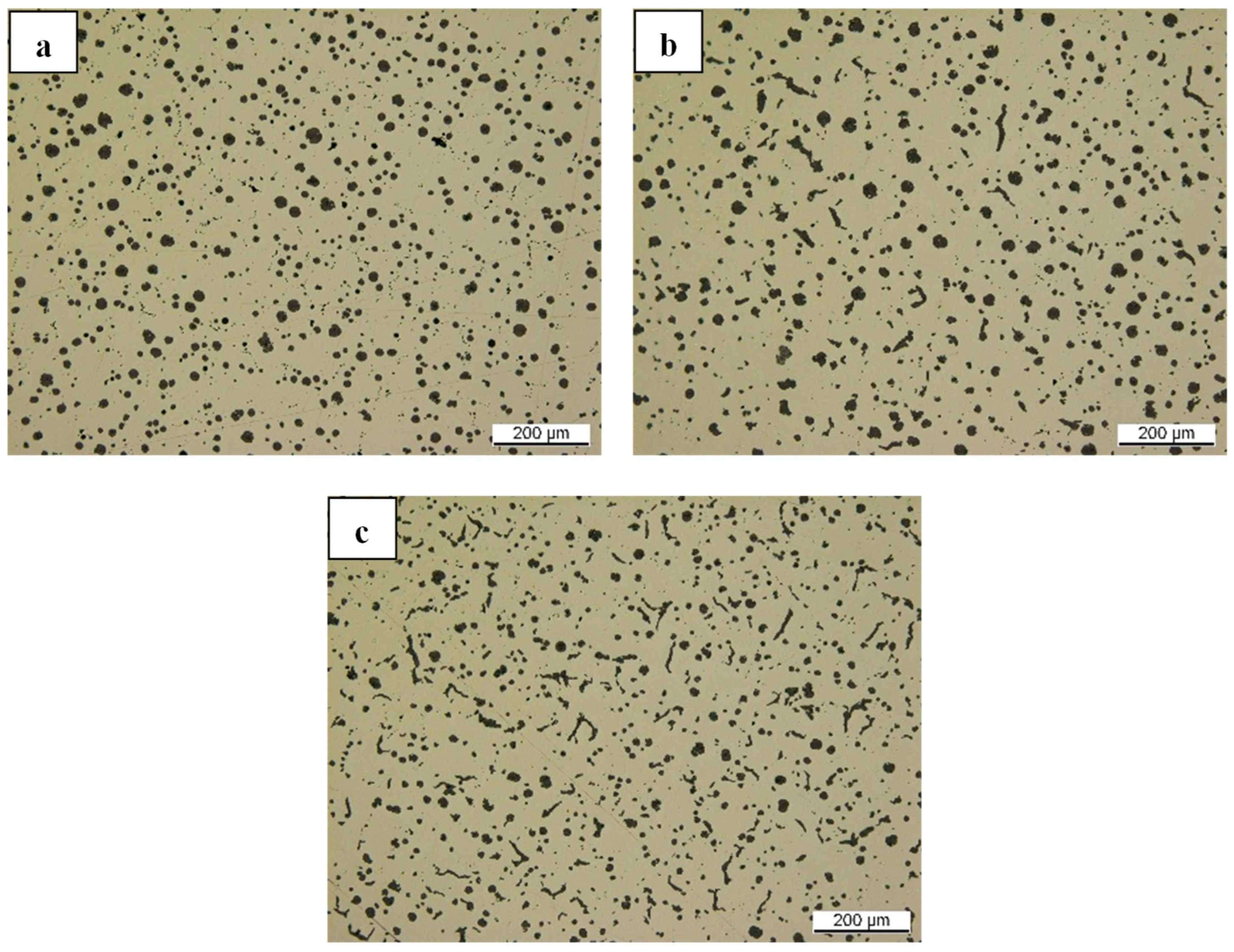
Nodular graphite can eventually be observed in the cast iron samples once 10 g of FeSiMg6 is used as a pocket treatment agent. Specifically, as shown in Figure 16a and Figure 17a, both LS-CI and HS-CI possess 100% spheroidal graphite, although their nodule sizes are not uniform. Furthermore, based on the observation in Figure 16, the graphite nodularity decreases with the reduced amount of FeSiMg6 introduced during the pocket treatment. A similar effect could also be observed in Figure 17 for increasing the remaining sulfur content. It is indicated that the count of spheroidal graphite decreases, followed by the formation of vermicular and, eventually, lamellar graphites.
A certain degree of graphite nodularity could also be observed if Mg-bearing materials and FeSi-CeLa were used as pocket treatment agents. As shown in Figure 18, round spheroidal graphite solidified, mainly if 5 g of Mg-AlSn or NiMg15 was used. Although some nodules were documented as 5 g of FeSi-CeLa was utilized, vermicular graphite structures were also established. Additionally, in contrast to the results for FeSiMg6, the cast iron matrix depicted in Figure 18 indicates the formation of a white iron (carbide) structure.
Based on the observation results in Figure 17, which indicate the effect of the remaining sulfur content, Ca-bearing materials were utilized as pocket treatment agents. However, as documented in Figure 19, no nodular graphite can be identified after using 5 g of CaSi as a pocket treatment agent. Comparable behavior was also recognized in other experiments that used 5 g of Ca or CaC2 as treatment agents for all samples. Like CaSi, using another silicon-bearing material (10 g of FeSi75) as a pocket treatment agent also delivered no nodulizing effect, as indicated in Figure 20. A similar result of predominantly lamellar graphite formation was also shown if 10 g of SiC was utilized as a pocket treatment agent within the boundary of a similar experimental setup in Figure 3.

3.3. Effect of Nonmetallic Inclusion on the Graphite Structure upon Pocket Treatment

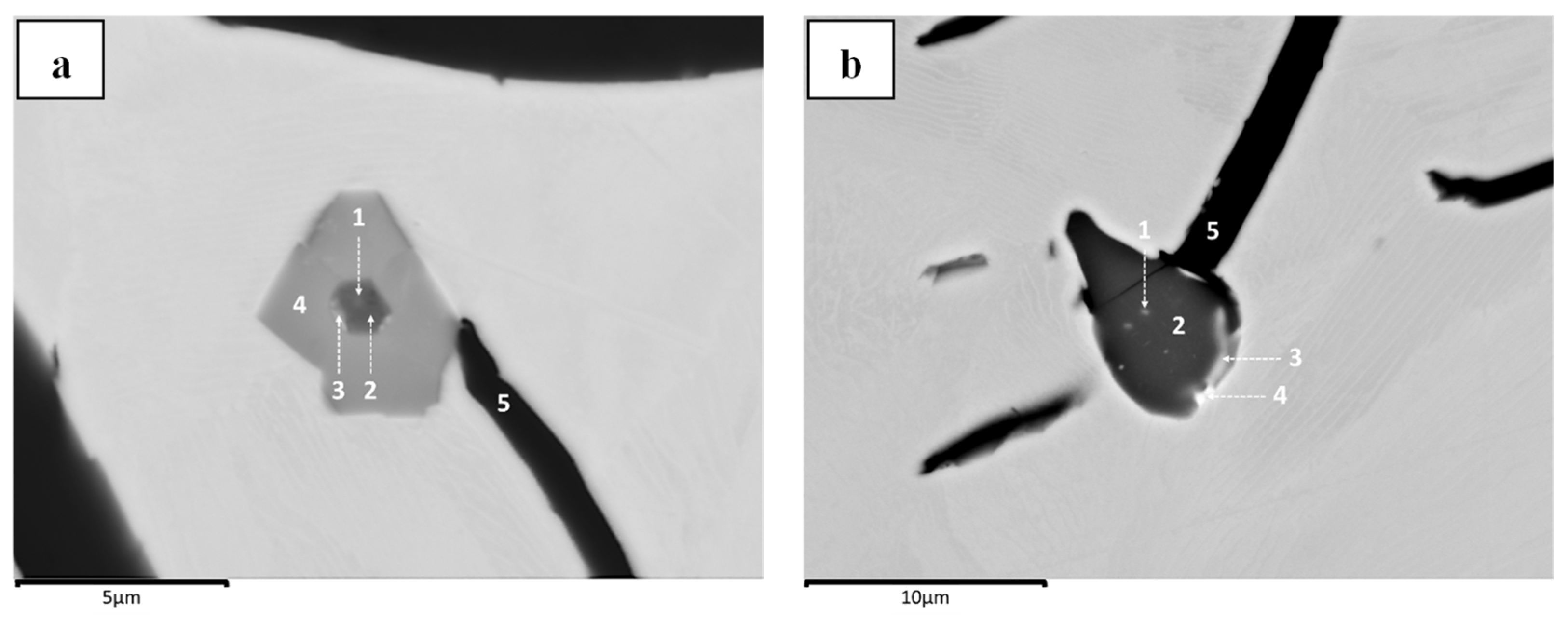
In addition to the microstructure analysis of the graphite morphology related to the treatment agents, the intriguing behavior of graphite nucleation on nonmetallic inclusions was also revealed. As shown in Figure 21a,b as detailed observations of LS-CI in Figure 15a and HS-CI in Figure 17c, respectively, lamellar graphite is observed to grow heterogeneously on inclusions with the chemical compositions documented in Table 6 and Table 7, respectively.
Based on the analysis in Table 6, a possible configuration of the Mg-O-S core covered with a Ti-N configuration is suggested. In another case, Table 7 shows a mixture of Mn-S and Mg-S inclusion systems where minor sulfides of Ce and La were also detected. Notably, the origin of Mg in both samples is distinguishable (as residual compared to an addition). Yet, both were insufficient to induce nodular graphite formation.
In the case of varying the sulfur content provided in Figure 17, the number of graphite nodules increases with decreasing sulfur content. This change in the sulfur content was also observed to influence the chemical composition of the inclusion, where no significant involvement of manganese was detected. As summarized in Table 8, based on detailed observations of nodular graphite nucleated on the HS-CI in Figure 17b, distinct configurations of Mg-containing inclusions were revealed, as depicted in Figure 22. In addition to those Mg-bearing inclusions, several Al-containing oxides were also captured, which were also associated with the nucleation of the graphite structure. As shown in Figure 23, despite having an identical morphology with an approximately Al-O composition, the graphite structures that grow on those inclusions do not necessarily follow similar behaviors.

4. Discussion

4.1. The Interplay Between Inclusions, Liquid Composition, and Graphite Development

As shown in Figure 8, detecting an Mg-O-based system in the center of a well-preserved graphite nodule suggests that this nodular graphite nucleated heterogeneously. However, this establishment of Mg-O alone does not guarantee that the nucleated graphite grows as nodular graphite. As captured in Figure 10b and Figure 21a, distinct graphite morphologies of nodular and lamellar graphite are captured, respectively, despite possessing a comparable composition of nonmetallic compounds as their heterogeneous nucleation sites by exhibiting a certain extent of Mg-O and Ti-N configurations. In this context, despite originating from a similar LS-CI sample, the examination in Figure 21a resulted from the re-melting process at 1500 °C (in Figure 15a) instead of at 1200 °C for controlled dissolution (as in Figure 10b); hence, significant fading of the remaining magnesium (measured at less than 30 ppm) is highly anticipated. Based on these findings, it is suggested that graphite nucleation should not always immediately start with the availability of the Mg-O nonmetallic system since it can also provide a nucleation site for another compound before (or parallel with) graphite nucleation.
Moreover, although nonmetallic inclusions might induce or trigger graphite nucleation, the abovementioned results reaffirm that the concentration of magnesium in molten iron has a more pivotal role in determining the nucleation and growth of nodular graphite, as further amplified in Figure 16, which aligns well with [41,42]. On the other hand, it is also essential to note that the residual dissolved magnesium concentration is related to the dissolved oxygen content in molten cast iron [43]; thus, the presence of Mg-O should be attributed to the oxidation of magnesium. This formation is crucial because only the Mg-O system established during the process can preferably serve as an effective graphite nucleation site since the direct introduction of MgO particles has been industrially proven to be a disadvantage [44].
The residual sulfur concentration could also influence the remaining dissolved magnesium in molten cast iron [45]. However, it is worth noting that the desulfurization reaction to MgS can proceed just after a specific low level of dissolved oxygen has been attained [46]. In the context of nucleation, this reaction will produce the Mg-S inclusion system, which could serve as an effective nucleation site for graphite as either a dominant compound (Figure 22b) or coexist with Mg-O (Figure 9). As already explored in the Mg-O system, solely establishing the Mg-S inclusion system could not determine whether the graphite would nucleate on its surface. Concurrently, assuming that graphite nucleation has started, it does not necessarily mean that a nodular graphite structure will develop, as shown in Figure 21b, where a lamellar graphite structure grows instead.
Given the circumstances of the abovementioned observed sample (HS-CI with 0.1 wt.% S with 10 g of FeSiMg6 as a pocket treatment agent captured in Figure 17c), the formation of the Mg-S system is expected to occur early during solidification [47]. However, no graphite nucleation was directly started, and sulfide formation consisting of Mg-Mn was preferred because of the limited amount of magnesium compared to sulfur content. This sulfide facilitates the nucleation and growth of lamellar graphite, amplifying the results documented in [48]. Furthermore, this sulfide system also provides a nucleation site for an oxy-sulfide containing Ce and La originating from FeSiMg6, as suggested in [36]. Hence, as depicted in Figure 17, enhancing the previous results documented in [49,50], achieving certain low levels of sulfur and oxygen is crucial for promoting the growth of nodular graphite.
Despite the anticipated low solubility limit in molten cast iron [51,52], the introduction of magnesium-bearing materials should be followed by a dissolution process if the dissolved oxygen and sulfur concentrations are maintained at lower levels than the critical thresholds. Considering that FeSiMg6 was utilized, the introduction of Mg involves the dissolution of Mg2Si, which has a melting point of ca. 1100 °C [53]. In this instance, the graphite is expected to be able to start its nucleation at an early stage of dissolution, as indicated in Figure 22c, where high Mg and Si contents are detected.
On the other hand, this inhomogeneous dispersion could also induce nitridation of Mg2Si, producing the core structure shown in Figure 6b. This nitrogen interaction arises from the decreasing solubility with increasing concentrations of carbon and silicon [54,55], which could be triggered by segregation associated with FeSi dissolution. Moreover, since the silicon content increases, the solubility of carbon decreases [56] and might be, to a certain extent, favorable for graphite nucleation on MgSiN2, forming the structure depicted in Figure 12. Similarly, since FeSi has no direct nodularization effect, as shown in Figure 20, which strengthens previous findings in [23,57], the nucleated graphite could only eventually develop into a nodular structure because of the low oxygen and sulfur concentrations coupled with a sufficient dissolved magnesium concentration in molten cast iron.

4.2. The Importance of Inclusion and Magnesium to the Growth of Nodular Graphite

Since the composition of inclusions varies despite originating from one iron sample, it is suggested that no definite format is required for graphite nucleation. This case is supported by the fact that the graphite structure can nucleate on a single system based on magnesium (Figure 8), silicon (Figure 11a), and cerium (Figure 6c), as well as start congruently with the nucleation chain as in staged (Figure 13), compound (Figure 10a) and complex (Figure 14) configurations. The formation of this variance also suggests that either inhomogeneity or segregation was involved in inclusion formation, as supported by the results of Figure 22. In this case, three different inclusions were found in one similar sample of HS-CI in Figure 17b. These chemical compositions should be thermodynamically chronological (A1: Mg-O system first—then B2: Mg-S format—and eventually C3: Mg-Si) yet detected as a coexistence.
The findings of this study also substantiate that there is no direct relationship between the composition or morphology of inclusions and the growth of nodular graphite. In addition to the case explored earlier, despite being revealed as a nucleus in Figure 11a, the utilization of SiC as a pocket treatment agent showed no nodularization effect, which is analogous to the direct involvement of MgO. In the case of morphology, as highlighted in Figure 23, despite the similar nucleus shape as a predominant Al-O system was established, the associated graphite developed toward a different structure (coexists in one similar HS-CI in Figure 17b). Accordingly, it is suggested that the (local) liquid composition plays a pivotal role in the nucleation and growth of nodular graphite, which might be associated with the availability of dissolved magnesium, sulfur, and oxygen.
The role of magnesium in promoting the nucleation and growth of nodular graphite can also be observed as other Mg-bearing materials have been utilized. As indicated in Figure 18a,b, where Mg-AlSn and NiMg15 were employed, respectively, nodular graphite was established despite having a white iron matrix structure, as shown in Figure 24a,b. This carbide formation could be associated with Mg-overtreatment, as demonstrated in [58]. In this case, it is induced by either excessive addition or more efficient dissolution than FeSiMg6, as delineated in [59]. However, magnesium is not the only available alternative to produce nodular graphite, as revealed in Figure 18c. In this case, FeSi-CeLa (ca. 17 wt.% Ce and 14 wt.% La) was utilized as a pocket treatment agent without the involvement of magnesium. Compared with Mg-AlSn and NiMg15, the cast iron matrix also indicates a carbide system, as depicted in Figure 24c. These instances are congruently related to the possible excessive addition of Ce and La, which is also reported to be responsible for the observed deteriorated graphite structures, as provided in [60].
Calcium is also assumed as an element that promotes the nodularization of graphite in cast iron. Compared with magnesium, calcium has a high affinity for oxygen and sulfur and is thus commonly employed in deep desulfurization in the iron industry [61,62,63]. The solubilities of both magnesium and calcium in iron at 1600 °C are significantly low, ranging from 0.023 to 0.059 wt.% [51,52] and 0.024 to 0.046 wt.% [64,65,66], respectively. However, despite the resemblance in characteristics, no convincing nodularization effect can be observed, as shown in Figure 19, including by employing Ca and CaC2 in a similar trial setup (melting at 1500 °C and a pocket treatment).
In fact, there are only two published reports related to the nodularization process of SGI using CaSi [67,68] and one for Ca [69]. Based on the reported utilization of CaSi, a certain amount of Mg was measured in the CaSi employed in the studies; thus, distinguishing the effects of Mg or Ca given the total amount of approximately 5 to 10 wt.% introduced into the molten iron is unclear. Considering only the Ca-metal reported in [69], the expected quality of graphite nodularity was proven unattained. Moreover, the charge materials used during the investigation were pure Fe, metallic Si, and graphite, thus questioning the role of Ca since a similar approach was able to produce a treatment-free nodular graphite structure in cast iron [70], which will be explored in the next section.

4.3. Theoretical Dynamics in the Nucleation and Growth of Nodular Graphites

Based on the current results, two prerequisites are needed to produce commercial SGI: a low concentration of sulfur and oxygen coupled with the addition of magnesium or cerium-lanthanum. Since Mg, Ce, and La react with sulfur and oxygen during the treatment process, it is relatively easy to conclude that these metals act only as scavengers of surface-active elements, as proposed by Jung et al. [71]. In this context, the results of the present study suggest that they might not be utterly true since the use of Ca-bearing materials did not result in positive nodularity. Accordingly, a direct role of Mg, Ce, and La should also be expected during the growth of nodular graphite. Notably, heterogeneous nucleation cannot be perceived as indirect, as once proven by Dhindaw and Verhoeven [72] in the vacuum melting of synthetic Fe-C-Si alloys. Based on their report, nodular graphite can form at a specific cooling rate if high-purity iron is used, but this is not the case when ultrahigh-purity iron is utilized.
Consequently, it is convincing that the cause of nodular graphite establishment in synthetic Fe-C-Si alloys is, to a certain extent, comparable with that in commercial SGI, as revealed in the present study, particularly in explaining the role of Mg, Ce, and La. As key findings provided in [70,71,72], a high cooling rate and superheating are necessary to ensure the formation of nodular graphite in a carbide-containing cast iron matrix. These two factors are also known in foundry practice to be correlated with high undercooling, thus increasing the chill tendency, carbide formation, and carbon supersaturation degree of molten iron [73,74]. This carbon supersaturation as a determining factor in the growth of nodular graphite, as reported in [75], could be the intersection between synthetic and commercial SGI. As indicated in Figure 24, spheroidal graphite within a carbide-containing matrix associated with an excessive introduction of Mg, Ce, and La is also identified. It is correlated with the characteristics of those elements as carbide former, and their addition increases the degree of undercooling [58,76], contrasting with Ca, which tends to act as a graphitizer [69]. Accordingly, the supplementary role of Mg, Ca, and La in commercial SGI might be associated with increasing the degree of carbon supersaturation coupled with low sulfur and oxygen concentrations.
Despite the rational resonance between both phenomena in synthetic and commercial SGI regarding carbon supersaturation, further empirical investigations are necessary to describe precisely the mechanism of this complex and dynamic interaction. The hypothetical explanation might be related to the carbon solubility and activity since those factors are correlated with the dissolved sulfur and oxygen concentrations [77,78]. Furthermore, since carbide formation is involved, it is also conventionally known that the carbide stabilizers reduce the activity of carbon [79] as well as carbon equivalent (CE) [80] in molten iron, which might not be the case for Mg, Ce, and La. Specifically for Mg, the shift in the CE value and saturation degree is substantiated by a review of several experimental results provided in [81], which suggests that adding Mg during the treatment of molten iron displaces the liquidus line to the left. This shift would change the measured liquidus temperature, which is typically associated with an increasing CE. Since the solubility of Mg in austenite is negligible, the lowering liquidus temperature at the hypoeutectic composition indicates that the bulk of molten cast iron solidifies in supercooled circumstances, known as constitutional undercooling.
5. Conclusions

Based on the results revealed in the present study, the following conclusions could be drawn related to the nucleation and growth of nodular graphite in cast iron:
  • The alternative experimental approaches employed in this study were reliable for observing the nonmetallic nuclei of the graphite structure and effectively observing the established graphite structure related to variations in the treatment agents.
  • The graphite structure nucleated heterogeneously, but no such definite system of nonmetallic structure is required. In commercial SGI, the nucleus can be an oxy-sulfide, a carbo-nitride, or a complex compound between the two.
  • There was no direct correlation between the chemical composition or morphology of nonmetallic inclusions and the growth of the graphite structure. It is also indicated that graphite development is highly dependent on the chemical composition of molten iron, especially the establishment of any local segregation.
  • Low sulfur and oxygen concentrations are undoubtedly necessary, but the involvement of magnesium is not always obligatory in establishing nodular graphite. Nonetheless, it does not mean and is proven that the role of magnesium is not limited to being only a scavenger of those surface-active elements.
  • Another possible pivotal role of magnesium, including cerium and lanthanum, could be related to its behavior as a carbide stabilizer for enhancing carbon supersaturation in molten iron, thus increasing the driving force of nodular graphite formation.

Author Contributions

I.A.: conceptualization, methodology, formal analysis, investigation, data curation, writing—original draft, visualization. S.R.: methodology, validation, investigation, resources, data curation. J.K.: methodology, investigation, resources, writing—review and editing, visualization. M.G.: methodology, resources, supervision, project administration. R.D.: conceptualization, methodology, formal analysis, resources, writing—review and editing, supervision. All authors have read and agreed to the published version of the manuscript.

Funding

The authors acknowledge support from the Open Access Publication Fund of the University of Duisburg-Essen.

Data Availability Statement

The original contributions presented in this study are included in the article. Further inquiries can be directed to the corresponding authors.

Acknowledgments

The authors would like to acknowledge Max Frei, Martin Dehnen, and Roland Schmechel from the Institute of Technology for Nanostructures (NST), Universität Duisburg-Essen, for their support and assistance during the SEM/EDS data collection.

Conflicts of Interest

All the authors certify that they have no conflicts of interest to declare.

References

  1. World Foundry Organisation. Census of World Casting Production in Modern Casting; World Foundry Organisation: Kington, UK, 2017. [Google Scholar]
  2. Adey, C. Verfahren zur Herstellung von Grauguss Höherer Festigkeit. Germany Patent DRP Aktz. G98 710 VI/18b, 18 September 1939. [Google Scholar]
  3. Morrogh, H. Nodular Cast Iron and the Manufacture Thereof. U.S. Patent US2488511A, 15 November 1949. [Google Scholar]
  4. Millis, K.D.; Gagnebin, A.P.; Pilling, N.B. Cast Ferrous Alloy. U.S. Patent US2485760A, 25 October 1949. [Google Scholar]
  5. Hollomon, J.H.; Turnbull, D. Nucleation. Prog. Met. Phys. 1953, 4, 333–388. [Google Scholar] [CrossRef]
  6. Stefanescu, D.M. Cast Iron. In ASM Handbook Volume 15: Casting; ASM International: Novelty, OH, USA, 1988; pp. 168–181. [Google Scholar]
  7. Riposan, I.; Chisamera, M.; Stan, S. Enhanced Quality in Electric Melt Grey Cast Irons. ISIJ Int. 2013, 53, 1683–1695. [Google Scholar] [CrossRef]
  8. Krieger, W.; Trenkler, H. Die Deutung der Schmelzstrukturen von Eisen-Kohlenstoff- und Eisen-Nickel-Legierungen aus dem Viskositätsverhalten. Arch. Eisenhüttenwesen 1971, 42, 175–184. [Google Scholar] [CrossRef]
  9. Loper, C.R., Jr.; Shirvani, S.; Witter, T.H. Graphite Inoculants for Gray Cast Iron. MRS Online Proc. Libr. 1984, 34, 89–98. [Google Scholar] [CrossRef]
  10. Frost, J.M.; Stefanescu, D.M. Melt Quality Assessment of SG Iron through Computer-Aided Cooling Curve Analysis. AFS Trans. 1992, 100, 189–199. [Google Scholar]
  11. Fredriksson, H. Inoculation of Iron-base Alloys. Mater. Sci. Eng. 1984, 65, 137–144. [Google Scholar] [CrossRef]
  12. Semleit, T.; Adhiwiguna, I.; Wijaya, J.; Deike, R. Investigation of Silicon Carbide Dissolution Behavior in Molten Cast Iron under Specific Consideration of the Formation of Reaction Layers. Giess. Spec. 2021, 1, 46–53. [Google Scholar]
  13. Dhindaw, B.; Verhoeven, J.D. Inverse Chill and Nodular Graphite Formation in Synthetic Cast Irons Melted and Cast under Vacuum. Trans. Jpn. Inst. Met. 1983, 24, 71–80. [Google Scholar]
  14. Stefanescu, D.M.; Alonso, G.; Larranaga, P.; Suarez, R. On the Stable Eutectic Solidification of Iron-Carbon-Silicon Alloys. Acta Mater. 2016, 103, 103–114. [Google Scholar] [CrossRef]
  15. Hara, T.; Kitagawa, T.; Kuroki, K.; Saikawa, S.; Terayama, K.; Ikeno, S.; Matsuda, K. Morphologies of Some Graphites in Ductile Cast Irons. Mater. Trans. 2014, 55, 1500–1505. [Google Scholar]
  16. Yamamoto, S.; Chang, B.; Kawano, Y.; Ozaki, R.; Murakami, Y. Mechanism of Nodularization of Graphite in Cast Irons Treated with Magnesium. Met. Sci. 1978, 12, 239–246. [Google Scholar] [CrossRef]
  17. Itofuji, H. Study of Voids in Chilled Samples of Magnesium Treated Irons. Int. J. Cast Met. Res. 2004, 17, 220–228. [Google Scholar]
  18. Jacobs, M.H.; Law, T.J.; Melford, D.A.; Stowell, M.J. Basic Process Controlling the Nucleation of Graphite Nodules in Chill Casting Iron. Met. Technol. 1974, 1, 490–500. [Google Scholar]
  19. Francis, B. Heterogeneous Nuclei and Graphite Chemistry in Flake and Nodular Cast Irons. Metall. Trans. A 1979, 10, 21–31. [Google Scholar]
  20. Alonso, G.; Larranaga, P.; De la Fuente, E.; Stefanescu, D.M.; Natxiondo, A.; Suarez, R. Kinetic of Nucleation and Growth of Graphite at Different Stages of Solidification for Spheroidal Graphite Iron. Int. J. Met. Cast. 2017, 11, 14–26. [Google Scholar]
  21. Qing, J.; Lekakh, S.; Xu, M.; Field, D. Formation of Complex Nuclei in Graphite Nodules of Cast Iron. Carbon 2021, 171, 276–288. [Google Scholar]
  22. Deike, R.; Smaha, B.; Maqbool, S. Was macht Magnesium bei der Magnesiumbehandlung. Giesserei 2021, 9, 33–39. [Google Scholar]
  23. Cochard, V.; Harding, R.A.; Campbell, J.; Herold, R. Inoculation of Spheroidal Graphite Cast Iron. Adv. Mater. Res. 1997, 4–5, 277–284. [Google Scholar]
  24. Igarashi, Y.; Okada, S. Observation and Analysis of the Nucleus of Spheroidal Graphite in Magnesium-treated Ductile Iron. Int. J. Cast Met. Res. 1998, 11, 83–88. [Google Scholar] [CrossRef]
  25. Alonso, G.; Stefanescu, D.M.; Larranaga, P.; De la Fuente, E.; Aguado, E.; Suarez, R. Solidification of Superfine Graphite Iron Revealed by Interrupted Solidification Experiments. Int. J. Cast Met. Res. 2016, 29, 258–265. [Google Scholar]
  26. Michels, L.; Pires, A.J.F.; Riberio, C.A.S.; Kroka, B.; Hoel, E.G.; Ott, E.; Hartung, C. Effect of Holding Time on Populations of Microparticles in Spheroidal Graphite Irons. Metall. Mater. Trans. B 2022, 53, 836–847. [Google Scholar]
  27. Solberg, J.K.; Onsoien, M.I. Nuclei for Heterogeneous Formation of Graphite Spheroids in Ductile Cast Iron. Mater. Sci. Technol. 2001, 17, 1238–1242. [Google Scholar]
  28. Laffont, L.; Pugliara, A.; Hungria, T.; Lacaze, J. STEM Observation of a Multiphase Nucleus of Spheroidal Graphite. J. Mater. Res. Technol. 2020, 9, 4665–4671. [Google Scholar]
  29. Stefanescu, D.M.; Alonso, G.; Larranaga, P.; De la Fuente, E.; Suarez, R. Reexamination of Crystal Growth Theory of Graphite in Iron-Carbon Alloys. Acta Mater. 2017, 139, 109–121. [Google Scholar]
  30. Michels, L.; Cygan, B.; Pawlyta, M.; Jezierski, J.; Götz, A.; Akola, J. Graphite Nucleation on (Al,Si,Mg)-Nitrides: Elucidating the Chemical Interactions and Turbostratic Structures in Spheroidal Graphite Cast Irons. Carbon 2024, 220, 118484. [Google Scholar]
  31. Tartera, J.; Llorca-Lsern, N.; Marsal, M.; Puig, M.; Espanol, M. Confocal Microscope Observation of Graphite Morphology. Int. J. Cast Met. Res. 1999, 11, 459–464. [Google Scholar]
  32. Stefanescu, D.M.; Crisan, A.; Alonso, G.; Larranaga, P.; Suarez, R. Growth of Spheroidal Graphite on Nitrid Nuclei: Disregistry and Crystallinity During Early Growth. Metall. Mater. Trans. A 2019, 50, 1763–1772. [Google Scholar]
  33. Jacobs, M.H.; Law, T.J.; Melford, D.A.; Stowell, M.J. Identification of Heterogeneous Nuclei for Graphite Spheroids in Chill-Cast Iron. Met. Technol. 1976, 3, 98–107. [Google Scholar]
  34. Celis, M.M.; Domenges, B.; Hug, E.; Lacaze, J. Analysis of Nuclei in a Heavy-Section Nodular Iron Casting. Mater. Sci. Forum 2018, 925, 173–180. [Google Scholar]
  35. Skaland, T.; Grong, O.; Grong, T. A Model for the Graphite Formation in Ductile Cast Iron: Part I. Inoculation Mechanisms. Metall. Trans. A 1993, 24, 2321–2345. [Google Scholar]
  36. Nakae, H.; Igarashi, Y. Influence of Sulfur on Heterogeneous Nucleus of Spheroidal Graphite. Mater. Trans. 2002, 43, 2826–2831. [Google Scholar]
  37. Adhiwiguna, I.; Nobakht, N.; Deike, R. Nodular Graphite Dissolution and Nucleus Observation: High-Temperature Dynamics of Ductile Iron Recycling. Metals 2024, 14, 915. [Google Scholar] [CrossRef]
  38. Adhiwiguna, I.B.G.S. Role of Magnesium in the Production of Nodular Graphite Cast Iron: An Assessment on Reaction Mechanism and Sustainable Substitute. Ph.D. Thesis, Universität Duisburg Essen, Duisburg, Germany, 2025. [Google Scholar]
  39. Adhiwiguna, I.B.G.S.; Karagülmez, G.; Keskin, O.; Deike, R. Investigation on Applicability of Lime as Desulfurization Agent for Molten Cast Iron. Steel Res. Int. 2025, 96, 2400416. [Google Scholar]
  40. Adhiwiguna, I.; Vellayadevan, K.; Tekneci, Y.; Walz, M.; Algermissen, D.; Deike, R. Algermissen and R. Deike. Industrial Ecotechnological Assessment of Lime as a Sustainable Substitute for Desulfurization of Cast Iron. J. Sustain. Metall. 2024, 10, 797–809. [Google Scholar]
  41. Dawson, S. Process Control for the Production of Compacted Graphite Iron. In Proceedings of the 106th AFS Casting Congress, Kansas City, MO, USA, 4–7 April 2002. [Google Scholar]
  42. Hernando, J.C.; Domeij, B.; Gonzalez, D.; Amieva, J.M.; Dioszegi, A. New Experimental Technique for Nodularity and Mg Fading Control in Compacted Graphite Iron Production on Laboratory Scale. Metall. Mater. Trans. A 2017, 48, 5432–5441. [Google Scholar]
  43. Mampaey, F.; Habets, D.; Seutens, F. The Use of Oxygen Activity Measurement to Determine Optimal Properties of Ductile Iron during Production. Giessereiforschung 2008, 60, 2–19. [Google Scholar]
  44. Sheng, D.; Li, S.-J.; Lu, Y.-M.; Lin, X.-Y.; Chen, S.-C. Critical Content of MgO in Spheroidisers. J. Iron Steel Res. Int. 2006, 13, 1–4. [Google Scholar]
  45. Han, Q.; Zhou, D.; Xiang, C. Determination of Dissolved Sulfur and Mg-S, Mg-O Equilibria in Molten Iron. Steel Res. 1997, 68, 9–14. [Google Scholar]
  46. Yang, J.; Kuwabara, M.; Sakai, T.; Uchida, N.; Liu, Z.; Sano, M. Simultaneous Desulfurization and Deoxidation of Molten Steel with in Situ Produced Magnesium Vapor. ISIJ Int. 2007, 47, 418–426. [Google Scholar]
  47. Zhang, T.-S.; Wang, D.-Y.; Jiang, M.-F. Effect of Magnesium on Evolution of Oxide and Sulphide in Liquid Iron at 1873K. J. Iron Steel Res. Int. 2014, 21, 1073–1080. [Google Scholar]
  48. Stefan, E.; Chisamera, M.; Riposan, I.; Stan, S. Graphite Nucleation Sites in Commercial Grey Cast Irons. Mater. Proc. 2021, 45, 4091–4095. [Google Scholar] [CrossRef]
  49. Suarez, O.M.; Kendrick, R.D.; Loper, C.R., Jr. Late Sulfur Inoculation of Spheroidal Graphite Cast Irons. Int. J. Cast Met. Res. 2003, 16, 1–6. [Google Scholar] [CrossRef]
  50. Bazdar, M.; Abbasi, H.R.; Yaghtin, A.H.; Rassizadehghani, J. Effect of Sulfur on Graphite Aspect Ratio and Tensile Properties in Compacted Graphite Irons. J. Mater. Process. Technol. 2009, 209, 1701–1705. [Google Scholar] [CrossRef]
  51. Zhang, X.; Han, Q.; Chen, D. Dissolution Equilibrium of Magnesium Vapor in Liquid Iron. Metall. Trans. B 1991, 22B, 918–921. [Google Scholar] [CrossRef]
  52. Mikhailov, G.G.; Samoilova, O.V.; Makrovets, L.A.; Smirnov, L.A. Thermodynamic Modeling of Isotherms of Oxygen Solubility in Liquid Metal of the Fe-Mg-Al-O System. Steel Transl. 2019, 49, 522–527. [Google Scholar] [CrossRef]
  53. Nayeb-Hashemi, A.; Clark, J.B. The Mg-Si (Magnesium-Silicon) System. Bull. Alloy Phase Diagr. 1984, 5, 584–592. [Google Scholar] [CrossRef]
  54. Maekawa, S.; Nakagawa, Y. Solubility of Nitrogen in Liquid Iron and Effect of Carbon, Silicon and Manganese on the Solubility. Tetsu-to-Hagane 1960, 46, 748–753. [Google Scholar] [CrossRef]
  55. Jang, J.-M.; Kim, D.-H.; Paek, M.-K.; Pak, J.-J. Nitrogen Solubility in Cast Iron Containing C, Si and Mn. ISIJ Int. 2018, 58, 1185–1190. [Google Scholar] [CrossRef]
  56. Ahn, S.H.; Kim, Y.H.; Shin, J.-P.; Lee, Y.E. Thermodynamic Assessment of Liquid Fe-Si-C System by Unified Interaction Parameter Model. ISIJ Int. 2014, 54, 750–755. [Google Scholar] [CrossRef]
  57. Fras, E.; Lopez, H.F.; Podrzucki, C. The Influence of Oxygen on the Inoculation Process of Cast Iron. Int. J. Cast Met. Res. 2000, 13, 107–121. [Google Scholar] [CrossRef]
  58. Suarez, R.; Sertucha, J.; Larranaga, P.; Lacaze, J. Active Mg Estimation using Thermal Analysis: A Rapid Method to Control Nodularity in Ductile Cast Iron Production. Metall. Mater. Trans. B 2016, 47, 2744–2753. [Google Scholar]
  59. Fesenko, M.A.; Fesenko, A.M. In-Mould Graphitizing, Spheroidizing, and Carbide Stabilizing Inoculation of Cast Iron Melt. Prog. Phys. Met. 2020, 21, 83–101. [Google Scholar]
  60. Stefanescu, D.M.; Loper, C.R., Jr. Effect of Lanthanum and Cerium on the Structure of Eutectic Cast Iron. Am. Foundrymen’s Soc. Trans. 1981, 89, 425–436. [Google Scholar]
  61. Ototani, T.; Kataura, Y. Deoxidation and Desulfurization of Liquid Steel with Calcium Complex Alloys. Trans. ISIJ 1972, 12, 334–342. [Google Scholar]
  62. Numata, M.; Higuichi, Y. Effect of Changes in Sulfur and Oxygen Concentration on Change in Nitrogen Concentration in Liquid Steel during CaO-CaSi Powder Blowing under Reduced Pressure. ISIJ Int. 2012, 52, 2019–2025. [Google Scholar] [CrossRef]
  63. Bulko, B.; Molnar, M.; Demeter, P.; Cervenka, M.; Trefa, G.; Mochnacka, M.; Baricova, D.; Hubatka, S.; Fogaras, L.; Sabik, V. Deep Steel Desulfurization Practice. Trans. Indian Inst. Met. 2022, 75, 2807–2816. [Google Scholar] [CrossRef]
  64. Ototani, T.; Kataura, Y.; Degawa, T. Calcium Deoxidation and Aluminium Desulphurization of Liquid Iron and Liquid Iron Alloy with a Lime Crucible. Tetsu-to-Hagane 1975, 61, 2167–2181. [Google Scholar]
  65. Song, B.; Han, Q. Equilibrium of Calcium Vapor with Liquid Iron and the Interaction of Third Elements. Metall. Mater. Trans. B 1998, 29B, 415–420. [Google Scholar] [CrossRef]
  66. Berg, M.; Lee, J.; Sichen, D. Study on the Equilibrium Between Liquid Iron and Calcium Vapor. Metall. Mater. Trans. B 2017, 48B, 1715–1720. [Google Scholar] [CrossRef]
  67. Kusakawa, T. Effects of Calcium Silicide on Cast Iron (I). Tetsu-to-Hagane 1952, 38, 376–382. [Google Scholar]
  68. Imasogie, B.I.; AAfonja, A.; Ali, J.A. Properties of As-Cast and Heat-Treated Nodular Graphite Cast Irons, Melts Treated with CaSi-CaF2 Alloy. Scand. J. Metall. 2001, 30, 91–102. [Google Scholar] [CrossRef]
  69. Maruyama, M.; Chida, H. Effects of Calcium on the Cast Iron Molten under Vacuum. J. Jpn. Foundrymen’s Soc. 1958, 30, 880–886. [Google Scholar]
  70. Doi, M.; Nishi, S.; Ueda, Y. Formation of Inverse Chill and Spheroidal Graphite in High Purity Cast Iron. J. Jpn. Foundrymen’s Soc. 1973, 45, 871–877. [Google Scholar]
  71. Jung, S.; Ishikawa, T.; Nakae, H. Critical Conditions for Formation of Spheroidal Graphite. Mater. Sci. Eng. A 2008, 476, 350–356. [Google Scholar]
  72. Dhindaw, B.; Verhoeven, J.D. Nodular Graphite Formation in Vacuum Melted High Purity Fe-C-Si Alloys. Metall. Trans. A 1980, 11, 1049–1057. [Google Scholar]
  73. Neacsu, E.L.; Riposan, I.; Cojocaru, A.M.; Stan, S.; Stan, I. Carbide to Graphite Transition Control by Thermal Analysis in Grey Cast Irons. Metals 2020, 10, 933. [Google Scholar] [CrossRef]
  74. Patterson, W.; Ammann, D. Beitrag zur Kristallisation des lamellaren Eisen–Graphit–Entektikume in Gusseisen. Giess. Techn.–Wiss. Beih. 1959, 23, 1245–1247. [Google Scholar]
  75. SSubramanian, V.; Purdy, G.R. Graphite Morphology Control in Cast Iron. Mater. Res. Soc. Symp. Proc. 1985, 34, 47–56. [Google Scholar]
  76. Onsøien, M.I.; Grong, Ø.; Skaland, T.; Jørgensen, K. Mechanism of Graphite Formation in Ductile Cast Iron Containing Rare Earth Metals. Mater. Sci. Technol. 1999, 15, 253–259. [Google Scholar]
  77. Morris, J.P.; Buehl, R.C. The Effect of Carbon on the Activity of Sulfur in Liquid Iron. J. Miner. Met. Mater. Soc. 1950, 2, 317–322. [Google Scholar]
  78. Banya, S.; Matoba, S. Activity of Carbon and Oxygen in Liquid Iron. Tetsu-to-Hagane 1963, 13, 1922–1930. [Google Scholar] [CrossRef] [PubMed]
  79. Kagawa, A.; Okamoto, T. Coefficients for Equilibrium Partition of A Third Element between Solid and Liquid in Iron-Carbon base Ternary Alloys and Their Relation to Graphitization during Iron-Carbon Eutectic Solidification. J. Mater. Sci. 1984, 19, 2306–2318. [Google Scholar] [CrossRef]
  80. Neumann, F.; Schenck, H.; Patterson, W. Einfluss der Eisenbegleiter auf Kohlenstofflöslichkeit, Kohlenstoffaktivität und Sättigungsgrad im Gusseisen; Westdeutscher: Köln und Opladen, Germany, 1966. [Google Scholar]
  81. Stefanescu, D.M. Analysis of the Rationale and Accuracy of the Use of Carbon Equivalent and Thermal Analysis in the Quality Control of Cast Iron. Int. J. Met. Cast. 2022, 16, 1057–1078. [Google Scholar] [CrossRef]
Figure 1. Flow chart of the experimental design considered in the present study.
Crystals 15 00347 g001
Figure 2. Experimental setup of controlled melting of the LS-CI sample.
Crystals 15 00347 g002
Figure 3. Experimental setup of pocket treatment of molten cast iron.
Crystals 15 00347 g003
Figure 4. Original microstructure of LS-CI in (a) as-polished and (b) nital-etched conditions under a light microscope observation with 500× magnification—P: pearlite, F: ferrite, G: graphite.
Crystals 15 00347 g004
Figure 5. Size spectrum of graphite nodules in different regions in LS-CI after controlled melting at <1200 °C—observed under a light microscope at 500× magnification.
Crystals 15 00347 g005
Figure 6. Nonmetallic inclusion detected within residual nodular graphites after a controlled melting trial—chemical composition of the notations refers to Table 2.
Crystals 15 00347 g006
Figure 7. Elemental mapping result of the commercial treatment agent FeSiMg6 in cast iron production.
Crystals 15 00347 g007
Figure 8. Structure of (a) residual graphite nodule with a trace of an (b) oxide nucleus—chemical composition of the notations refers to Table 3.
Crystals 15 00347 g008
Figure 9. Structure of residual graphite with a trace of oxy-sulfide nuclei—chemical composition of the notations refers to Table 3.
Crystals 15 00347 g009
Figure 10. Structure of residual graphite with a trace of oxy-sulfide nuclei coexisting with (carbo-) nitride—chemical composition of the notations refers to Table 3.
Crystals 15 00347 g010
Figure 11. Structure of residual graphite with a trace of (a) carbide and a (b) nitride nuclei—chemical composition of the notations refers to Table 4.
Crystals 15 00347 g011
Figure 12. Structure of (a) residual graphite nodule with a trace of a (b) nitride nucleus [37]—chemical composition of the notations refers to Table 4.
Crystals 15 00347 g012
Figure 13. Structure of (a) residual graphite modules with a trace of a (b) staged nucleus—chemical composition of the notations refers to Table 5.
Crystals 15 00347 g013
Figure 14. Structure of (a) residual graphite nodule with a trace of a (b) complex nucleus—chemical composition of the notations refers to Table 5.
Crystals 15 00347 g014
Figure 15. Graphite structures of (a) LS-CI, (b) HS-CI, and (c) AS-CI without involving treatment agents—observed under a light microscope at 100× magnification.
Crystals 15 00347 g015
Figure 16. Graphite structures of LS-CI with (a) 10, (b) 5, and (c) 2.5 g of FeSiMg6 as the treatment agent—observed under a light microscope at 100× magnification.
Crystals 15 00347 g016
Figure 17. Graphite structures of HS-CI containing (a) 0.002, (b) 0.04, and (c) 0.1 wt.% S with 10 g of FeSiMg6 as the treatment agent—observed under a light microscope at 100× magnification.
Crystals 15 00347 g017
Figure 18. Graphite structures of AS-CI with 5 g (a) Mg-AlSn, (b) NiMg15, and (c) FeSi-CeLa as treatment agents—observed under a light microscope at 100× magnification.
Crystals 15 00347 g018
Figure 19. Graphite structures of (a) LS-CI, (b) HS-CI, and (c) AS-CI with 5 g of CaSi as the treatment agent—observed under a light microscope at 100× magnification.
Crystals 15 00347 g019
Figure 20. Graphite structures of (a) LS-CI, (b) HS-CI, and (c) AS-CI with 10 g of FeSi75 as the treatment agent—observed under a light microscope at 100× magnification.
Crystals 15 00347 g020
Figure 21. Mg-modified inclusions as nucleation sites for lamellar graphite structures captured in (a) untreated LS-CI in Figure 15a and (b) HS-CI with 0.1 wt.% S in Figure 17c—chemical composition of the notations refers to Table 6 and Table 7, respectively.
Crystals 15 00347 g021
Figure 22. Mg-containing nonmetallic inclusions in the center of graphite nodules in HS-CI with 0.04 wt.% S in Figure 17b—chemical composition of the notations refers to Table 8.
Crystals 15 00347 g022
Figure 23. Al-containing oxide inclusions (in white circle) as possible heterogeneous nuclei of graphite structures in HS-CI with 0.04 wt.% S in Figure 17b.
Crystals 15 00347 g023
Figure 24. Matrix configuration in nital-etched conditions of AS-CI with 5 g of (a) Mg-AlSn, (b) NiMg15, and (c) FeSi-CeLa as treatment agents—observed under a light microscope at 200× magnification—P: pearlite, L: ledeburite, F: ferrite, G: graphite.
Crystals 15 00347 g024
Table 1. Initial chemical composition (wt.%) of cast iron samples.
CSiSMnMgFe
LS-CI3.4–3.62.1–2.3<0.0050.1–0.20.03–0.0493–94
HS-CI3.3–3.62.2–2.50.1–<0.0040.5–0.6<0.00593–94
AS-CI3.5–3.62.0–2.2<0.0090.05–0.1<0.00593–94
Table 2. Chemical composition (wt.%) of inclusions in residual graphite pointed in Figure 6.
Nr.CONSMgPFeSiAlCaCeLa
a155.9--0.2616.1-10.016.80.960.11--
a247.3-20.80.1613.0-5.112.90.760.07--
b365.4--0.053.6-26.84.00.17---
b437.8---5.9-50.45.70.30---
b554.9-23.70.108.1-5.27.70.32---
c658.810.8---0.233.20.2--26.8-
c763.08.1---0.402.50.1--25.50.48
Table 3. Chemical composition (wt.%) of oxy-sulfide nuclei in residual graphite.
NucleiCONSMgTiFeSiAlCaCeLa
Figure 8b49.320.4--20.12.26.41.50.2---
Figure 9a 131.422.9-2.512.8-30.3-----
Figure 9a 213.410.3-3.46.5-66.4-----
Figure 9b 134.925.4-6.518.1-15.1-----
Figure 9b 232.814.9-9.410.1-30.81.30.9---
Figure 10a 137.019.42.31.127.74.76.81.2----
Figure 10a 232.426.3-8.424.5-2.74.30.70.6--
Figure 10a 338.55.2-13.64.3-6.40.41.42.312.115.7
Figure 10b 158.317.4-0.714.55.03.4-0.8---
Figure 10b 253.311.27.90.27.714.05.20.20.3---
Table 4. Chemical composition (wt.%) of carbide and nitride nuclei in residual graphite.
NucleiCONSMgTiFeSiAl
Figure 11a32.10.4----0.966.6-
Figure 11b21.7-28.30.0622.60.171.624.21.3
Figure 12b 111.4-31.2-22.1-1.233.11.0
Figure 12b 216.9-30.6-20.1-2.229.30.9
Table 5. Chemical composition (wt.%) of the compounding nuclei in the residual graphite.
NucleiCONSMgTiFeSiAl
Figure 13b 129.39.47.2-4.85.534.46.13.3
Figure 13b 228.412.38.6-7.213.016.68.75.2
Figure 13b 336.015.49.40.248.4-6.216.87.4
Figure 13b 451.72.221.10.189.0-1.813.11.0
Figure 14b 139.511.813.9-5.026.92.6-0.3
Figure 14b 241.025.93.50.5016.410.31.50.30.6
Figure 14b 351.324.9-1.574.31.87.11.57.5
Figure 14b 464.915.71.31.206.61.37.30.61.3
Figure 14b 527.732.9-1.6516.4-9.91.210.3
Figure 14b 649.425.6-1.6616.7-4.50.71.6
Figure 14b 766.79.71.00.396.412.33.0-0.6
Table 6. Chemical composition (wt.%) of Mg-modified nitride as a nucleation site for lamellar graphite.
NucleiCONSMgTiFeMnCaCe
Figure 21a 1-20.46.73.013.945.85.10.40.51.6
Figure 21a 23.3-8.97.18.660.07.21.10.9-
Figure 21a 34.6-12.14.84.258.75.90.30.83.8
Figure 21a 4--16.80.20.465.312.6---
Figure 21a 554.5----0.444.8---
Table 7. Chemical composition (wt.%) of Mg-modified sulfide as a nucleation site for lamellar graphite.
NucleiCOSMgFeMnAlCaCeLa
Figure 21b 111.8-36.417.33.627.3--2.51.2
Figure 21b 29.8-36.017.88.927.8----
Figure 21b 36.8-17.812.343.79.9-0.13.35.3
Figure 21b 45.63.414.19.543.46.54.00.14.58.1
Figure 21b 580.2-0.1-19.10.2----
Table 8. Chemical composition (wt.%) of Mg-containing nuclei in graphite nodules pointed in Figure 22.
Nr.COSMgFeSiAlCa
a165.812.41.82.510.10.37.1-
b279.1-8.86.45.50.1-0.2
c375.6-0.48.63.29.42.8-
Disclaimer/Publisher’s Note: The statements, opinions and data contained in all publications are solely those of the individual author(s) and contributor(s) and not of MDPI and/or the editor(s). MDPI and/or the editor(s) disclaim responsibility for any injury to people or property resulting from any ideas, methods, instructions or products referred to in the content.