Review

Fly Ash-Supported Photocatalysts: Synthesis, Applications, and Advances in Modification Technology

1
School of Civil Engineering and Transportation, Guangzhou University, Guangzhou 510006, China
2
School of Civil Engineering, Putian University, Putian 351100, China
3
Engineering Research Center of Disaster Prevention and Mitigation of Southeast Coastal Engineering Structures (JDGC03), Fujian Province University, Putian 351100, China
4
Fujian Nanyu Engineering Construction Co., Ltd., Putian 351100, China
*
Authors to whom correspondence should be addressed.
Crystals 2025, 15(3), 223; https://doi.org/10.3390/cryst15030223
Submission received: 15 January 2025 / Revised: 18 February 2025 / Accepted: 20 February 2025 / Published: 26 February 2025
(This article belongs to the Special Issue Advances in Nanocomposites: Structure, Properties and Applications)

Abstract

:
Fly ash, a primary solid waste product of coal combustion, poses severe threats to human health and the environment due to its massive accumulation. Leveraging the modified porous structure and engineered adsorptive properties of fly ash, its integration with nano-photocatalytic materials can achieve dispersion and stabilization of the photocatalyst, significantly enhancing photocatalytic activity while enabling a synergistic effect between adsorption and photocatalysis. This paper focuses on the issue of agglomeration in semiconductor photocatalytic materials and briefly reviews the preparation methods and applications of modified fly ash-supported photocatalytic materials from both domestic and international perspectives in recent years. Initially, the properties and modification techniques of fly ash are analyzed, with a special emphasis on three methods for preparing fly ash-based photocatalytic composites: the sol-gel method, hydrothermal synthesis, and liquid-phase precipitation. A comparative analysis of the advantages and disadvantages of these three methods is conducted. Furthermore, the performance of the materials and the positive impacts of fly ash-composite photocatalysts are analyzed in terms of applications such as the degradation of pollutants in water, the degradation of NOx and VOCs gaseous pollutants, self-cleaning properties, and CO2 reduction capabilities. These analyses indicate that fly ash primarily serves as an adsorbent and carrier in these applications. However, as a carrier, fly ash possesses a limited number of active sites, and its modification technology is not yet fully mature. Additionally, research in this area is still in the experimental stage and has not transitioned to engineered production. Therefore, there is a need for continuous improvement in fly ash modification techniques. Furthermore, additional research should be conducted on functional building materials loaded with fly ash-supported photocatalytic materials to enhance their practicality.

1. Introduction

China, as the largest producer and consumer of coal globally, will continue to rely heavily on coal in its energy mix as its primary energy source for an extended period. According to statistics, China’s total annual coal consumption reached 2.93 billion tons. Fly ash, one of the most significant bulk solid wastes generated from coal combustion, is characterized by its high production volume and complex composition [1]. The production of fly ash has reached 781 million tons. The long-term storage of fly ash not only occupies vast amounts of land but also causes severe pollution to aquatic bodies, the atmosphere, soil, and other ecological environments, posing potential threats to human health. Therefore, the high-value utilization and recycling of fly ash is of utmost urgency.
Photocatalysis is a process that utilizes light energy for material conversion, involving chemical reactions under the combined action of light and catalysts [2,3]. It can be understood as the reverse reaction of photosynthesis, offering advantages such as low energy consumption, mild reaction conditions, and no secondary pollution. It is used for the degradation of organic and inorganic pollutants and holds great significance in addressing issues such as energy shortages and environmental degradation [4]. However, photocatalytic materials are mostly micro/nano-sized particles, prone to agglomeration, difficult to recycle, and may generate secondary pollution. Research has shown that selecting porous materials as carriers for photocatalysts can achieve dispersion and stabilization of the catalysts. Fly ash particles have potential applications in ion exchange, catalysis, and other fields [5,6]. In addition, recent studies have demonstrated that plasmonic metallic nanoparticles (e.g., Au, Ag), when integrated with carbon-based supports (e.g., graphene, carbon nanotubes), synergistically enhance light absorption and charge separation in semiconductor photocatalysts, thereby boosting their efficiency under visible-light irradiation [7,8].
In recent years, scholars have conducted in-depth research on topics related to the modification of photocatalytic materials using fly ash as a carrier. This paper reviews the recent advancements in research on fly ash-supported photocatalysts. By understanding the basic principles of photocatalysis for pollutant degradation and combining the properties of fly ash, the feasibility of using it as a carrier for photocatalysts is analyzed. Three methods for preparing fly ash-supported photocatalytic materials are introduced: the sol–gel method, hydrothermal synthesis, and liquid-phase precipitation. By elucidating the application research of fly ash-supported photocatalytic materials in various aspects, the achievements and future challenges faced in using fly ash as a photocatalyst carrier are summarized.

2. Properties of Fly Ash and Its Modification Methods

2.1. Properties of Fly Ash

Fly ash, a solid waste produced by thermal power plants and coal-fired boilers, exhibits properties closely related to the coal type and source, leading to significant variations [9]. Resembling cement in appearance, fly ash ranges in color from milky white to gray-black (reflecting its carbon content), with porous honeycomb-like particles that possess certain adsorptive properties [10,11]. It primarily includes CFB ash (from circulating fluidized bed boilers) and PC ash (from pulverized coal boilers). CFB ash features a rough surface and loose structure, while PC ash has a smooth surface and dense structure. Table 1 and Table 2 present the physical and chemical properties of fly ash.
Fly ash boasts a porous spherical particle structure and pozzolanic properties, along with numerous other advantages such as stable physicochemical properties, low cost, low density, high-temperature resistance, and a large specific surface area [13,14]. Specifically, fly ash microspheres exhibit a spectrum of morphological characteristics, which can be categorized into several distinct types based on their structural and compositional attributes. These include cenospheres, which are hollow spheres with smooth or textured surfaces and varying degrees of shell porosity; perforated globules, which feature surface or subsurface voids; plerospheres, composite particles encapsulating smaller secondary particulates; dermaspheres, spheres embedded with fine mineral crystallites; foamy spheres, characterized by reticulated, network-like structures with high internal porosity; dense microspheres, solid and non-porous particles; and ferrospheres, magnetic iron-rich microspheres. This morphological diversity underscores the complexity of fly ash as a heterogeneous material, necessitating meticulous characterization for specific applications.
Furthermore, the pozzolanic behavior of coal fly ash (CFA) is systematically defined. This classification categorizes CFA into two classes based on chemical composition and functional properties. Class F fly ash, derived from anthracite or bituminous coal combustion, is characterized by a SiO2 + Al2O3 + Fe2O3 content of at least 70%. It predominantly exhibits pozzolanic activity and requires a calcium source, such as portlandite, to form cementitious compounds. In contrast, Class C fly ash, produced from lignite or sub-bituminous coal, has a SiO2 + Al2O3 + Fe2O3 content of at least 50% and an elevated CaO content typically ranging from 15 to 30%. Class C ash demonstrates dual functionality, exhibiting both pozzolanic reactivity and intrinsic hydraulic cementitious properties due to its higher free lime content. This classification framework serves as a guide for selecting fly ash for construction applications. Where Class C is often preferred for its self-cementing capabilities, Class F requires alkaline activation.
Henceforth, the intricate porous architecture coupled with the essential chemical constituents, inclusive of SiO2, Al2O3, Fe2O3, and various other oxides, of fly ash qualifies it as an exemplary substrate for nano-photocatalysts. This serves to provide ample adsorption loci for contaminants, stabilize the catalyst nanoparticles, and augment the photogenerated charge separation dynamics via its unique electronic characteristics. Consequently, these attributes elevate the migration efficiency of electrons, thereby underpinning the suitability of fly ash as a superior support material for nano-photocatalysts in practical applications.

2.2. Modification Methods of Fly Ash

Fly ash possesses excellent physicochemical properties and a large specific surface area, qualifying it as a carrier. However, unmodified fly ash exhibits low surface activity, making it difficult to directly load catalysts. Therefore, research has shown that various modification techniques can activate fly ash, stimulate active surfaces, create porous surfaces with high active sites, disrupt its internal structure, and enhance its adsorption performance.

2.2.1. Physical Modification

Physical modification methods primarily involve altering the particle size of fly ash or damaging its internal structure through mechanical external forces, thereby increasing its specific surface area and exposing more active sites, significantly improving its adsorption performance. Common physical modification methods include mechanical grinding, high-temperature modification, and ultrasonic dispersion [15,16]. Mechanical grinding primarily involves applying external mechanical energy to disrupt the vitreous structure of fly ash, causing internal lattice distortions, breaking Si-O and Al-O bonds, and increasing defects, thereby increasing the specific surface area of fly ash and enhancing its ion exchange capacity. High-temperature modification involves using high temperatures to dry fly ash, exposing more pores and disrupting its internal structure, releasing active sites such as Si and Al, and improving adsorption performance. However, excessive roasting time or temperature can cause the pore structure of fly ash to collapse, sinter its internal components, and reduce activity. Ultrasonic dispersion utilizes the cavitation effect produced by ultrasonic waves at the solid–liquid interface, causing small liquid bubbles to rapidly release tremendous energy in a short time, forming local high temperatures and pressures, thereby damaging the structure of fly ash, generating more pores, reducing particle size, increasing the specific surface area, and achieving the purpose of modification.

2.2.2. Chemical Modification

Chemical modification primarily involves reacting chemical reagents with fly ash to disrupt its internal glassy phase structure, increase surface porosity, and enhance its specific surface area. Common chemical modification methods encompass acid modification, alkali modification, surfactant modification, and cationic modification. In acid modification, hydrochloric acid and sulfuric acid are often used as modifiers, reacting with oxides in fly ash other than silicon, thereby increasing the spacing between Si-O and Al-O bonds and augmenting the specific surface area and porosity. Additionally, the acid solution reacts with impurities within the pores of fly ash, serving to clear and enlarge the pores and increase the specific surface area. Furthermore, acid-modified fly ash possesses a positive zeta potential on its surface, enabling it to adsorb negatively charged pollutants.
Alkali modification commonly employs NaOH, Na2CO3, NH3·H2O, Ca(OH)2, and other alkaline auxiliaries, reacting with SiO2 and Al2O3 in fly ash to disrupt its glassy network structure and surface protective film, activating internal silicon and aluminum, increasing porosity within the fly ash, and enhancing its specific surface area [17]. Simultaneously, hydroxyl groups in an alkaline environment are prone to decomposition, generating negative ions, rendering the modified fly ash surface negatively charged, and facilitating electrostatic interaction with positively charged pollutants, thereby improving adsorption effectiveness. Surfactant modification primarily involves modifying the surface to create target functional groups, firmly adsorbing pollutants onto the fly ash surface. Common modifiers include coupling agents and surfactants. Cationic modification primarily utilizes the principle of ion exchange, employing inorganic salt impregnation for modification. Common modifiers can be classified as potassium, iron, sodium, aluminum, and calcium types.

3. Fly Ash Supported Photocatalytic Materials

Photocatalytic semiconductor materials often exhibit severe agglomeration as their particle size decreases. Solidification, including film solidification and carrier solidification, can effectively address the issue of powder agglomeration. Among these, carrier solidification is the most common method, involving the loading of micro/nano-sized particles onto carriers with developed pore structures and large specific surface areas, such as activated carbon and carbon nanotubes. The characteristics of common photocatalytic materials are outlined in Table 2. In recent years, fly ash has been selected as a carrier for photocatalytic materials in numerous studies. On the one hand, fly ash can effectively adsorb pollutants, maintaining a high concentration of pollutants on the catalyst surface, which favors the enhancement of catalytic efficiency. On the other hand, degraded intermediates can also be adsorbed, thereby avoiding secondary pollution. This approach not only reduces research costs but also provides a new pathway for the resource utilization of fly ash, enabling the synergistic treatment of pollutants and achieving the goals of resource conservation, environmental protection, and waste-to-waste treatment.
Table 2. Common photocatalytic materials [18].
ItemsBand Gap/eVAdvantagesDisadvantages
TiO23.2Good chemical stability; strong anti-corrosion abilityOnly responds to ultraviolet light; high recombination rate of photogenerated carriers
ZnO3.2Good chemical stability; strong anti-corrosion abilityOnly responds to ultraviolet light; high recombination rate of photogenerated carriers
BiOF3.6Has a special stable crystal structure; has visible light response performance; high photocatalytic activityThe energy of visible light is low; high recombination rate of photogenerated carriers
BiOCl3.5Good chemical stability; has high-value visible light response performance; has photocatalytic activityHigh recombination rate of photogenerated carriers; low photocatalytic activity
BiOBr2.6Has good chemical stability; has visible light response performanceHigh recombination rate of photogenerated carriers
BiOI1.8–1.9Good chemical stability; alkaline; acid-resistant; non-toxic and harmless; no heavy metal pollutionHigh recombination rate of photogenerated carriers
α-Fe2O32.0–2.2Has good chemical stability; simple preparation methodLow specific surface area; low visible light utilization rate
g-C3N42.7Has good chemical stability; has visible light response performanceHigh recombination rate of photo-generated carriers; low specific surface area is low; low utilization rate of visible light

3.1. Overview of Photocatalytic Technology

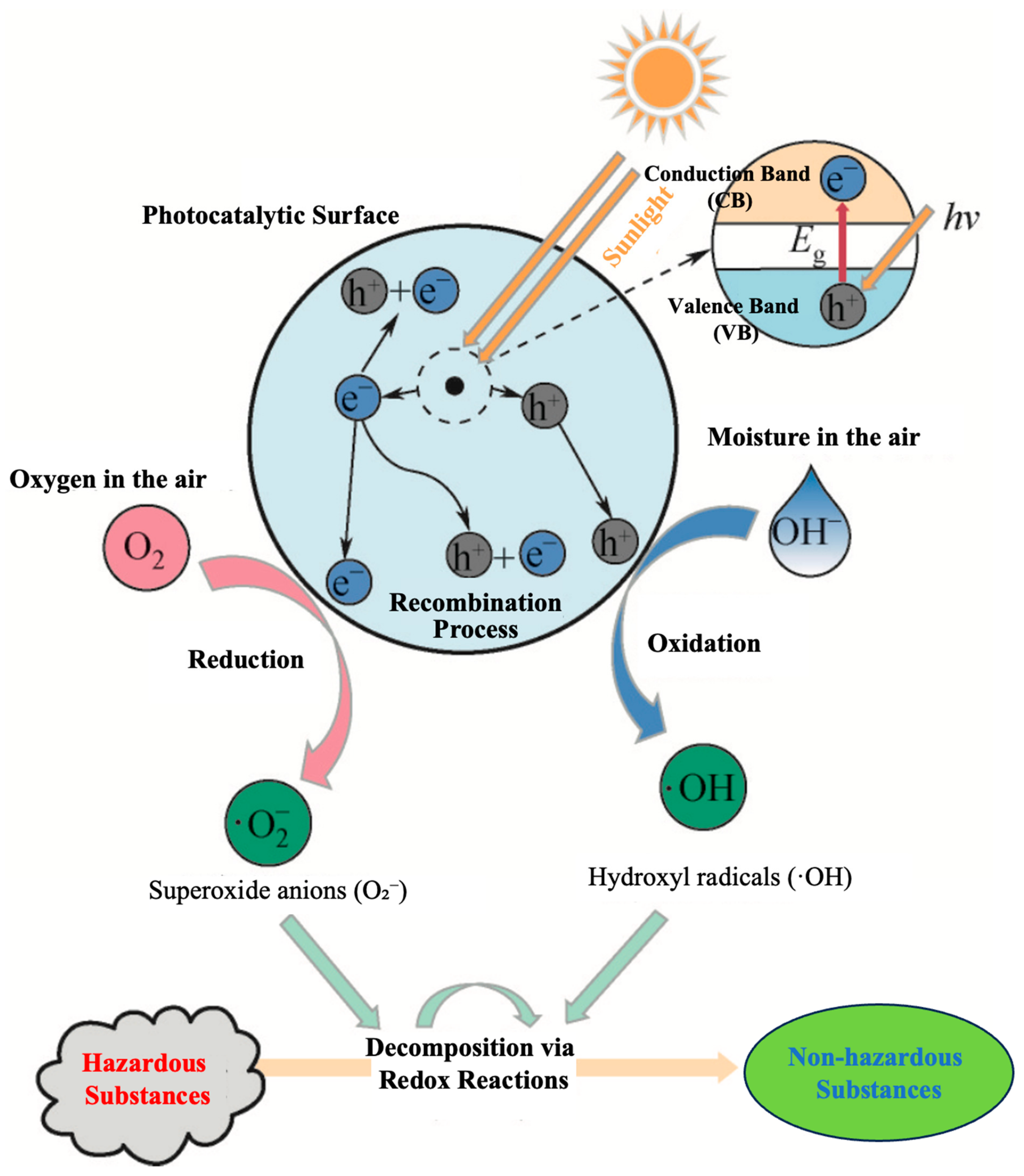
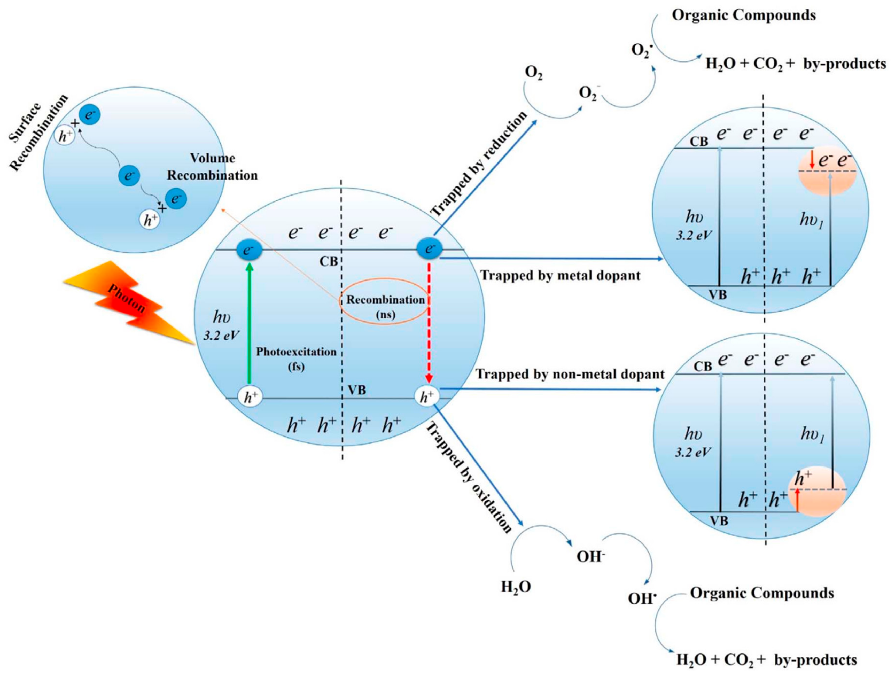
3.1.1. Mechanism of Photocatalytic Degradation

In 1972, Fujishima and Honda discovered that the surface of TiO2 could photo-decompose water under ultraviolet light irradiation, a phenomenon known as the “Honda–Fujishima Effect”, thereby opening the door to research on photocatalytic materials [18]. In 1976, a study found that TiO2 could degrade organic compounds into CO2 and H2O under illumination. Since then, semiconductor photocatalytic materials, represented by TiO2, have begun to develop. Semiconductor photocatalysis is an emerging green technology that can directly utilize solar energy to degrade environmental pollutants at room temperature and pressure. It has received extensive attention and research in recent decades due to its low energy consumption, simple operation, mild reaction conditions, and minimal secondary pollution.
Semiconductor crystals are formed by a large number of atoms bonding together. From the perspective of the atomic nucleus, the outermost energy band is known as the conduction band (CB), and the innermost energy band is known as the valence band (VB). The photocatalytic performance is closely related to the band structure of the catalyst material. Figure 1 illustrates the band structure distribution of semiconductors. Whether a photocatalytic material can react with pollutants adsorbed on its surface mainly depends on the potential of its valence band (VB) and conduction band (CB). The width of the forbidden energy between the valence band and the conduction band is called the band gap (Eg). The light absorption threshold λ of a semiconductor photocatalyst is related to its band gap Eg. A larger light absorption threshold λ corresponds to a smaller band gap Eg of the semiconductor photocatalyst, as shown in Equation (1).
E g = 1240 λ
When light with photon energy exceeding the bandgap value (hv > Eg) illuminates a photocatalyst, electrons in the valence band are excited to form photoelectrons (e), which then transition to the conduction band, leaving holes (h+) in the valence band. These photoelectrons (e) and holes (h+) migrate to the surface of the photocatalyst, thereby endowing the material surface with robust redox properties. These properties enable the oxidation and decomposition of pollutants. Simultaneously, the photoelectrons (e) migrating to the surface of the photocatalyst can reduce oxygen in the air to superoxide anions (·O2). The holes (h+) can oxidize water in the air to hydroxyl radicals (·OH). Hydroxyl radicals (·OH), possessing strong oxidizing properties, are the most crucial active species involved in the photocatalytic reaction, capable of rapidly and efficiently degrading a wide range of pollutants into small molecules such as CO2 and H2O. As illustrated in Figure 2, which depicts the mechanism of semiconductor photocatalysis, the reaction process is represented by Equations (2)–(8). In a more academic and detailed context, the photocatalytic process involves a series of complex reactions. Upon illumination, the electrons in the valence band absorb sufficient energy to overcome the bandgap and transition to the conduction band, creating a separation of charges. The migration of these charges to the surface of the photocatalyst triggers redox reactions, leading to the formation of reactive oxygen species (ROS), such as superoxide anions and hydroxyl radicals. These ROS are highly reactive and can attack pollutants, breaking down their chemical bonds and converting them into harmless or less harmful substances. The efficiency of the photocatalytic process depends on various factors, including the bandgap energy of the photocatalyst, the intensity and wavelength of the incident light, and the nature of the pollutants being degraded. Understanding and optimizing these factors is crucial for developing highly efficient photocatalysts for environmental remediation and other applications.
e + · O 2 · O 2
2 e + O 2 + 2 H + H 2 O 2
e + H 2 O 2 · O H + O H
O 2 + H 2 O 2 · O H + O H + O 2
H 2 O 2 2 · O H
h + + O H · O H
h + + H 2 O · O H + 2 H +

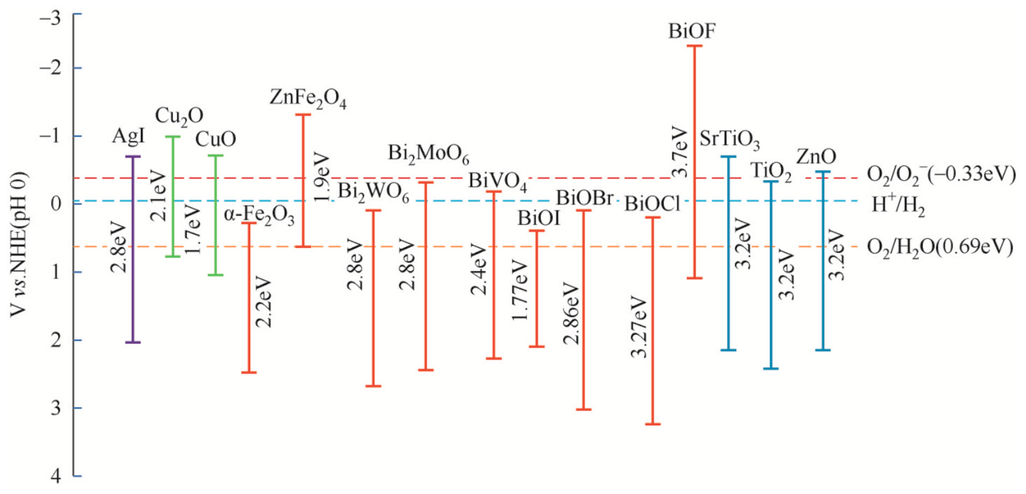
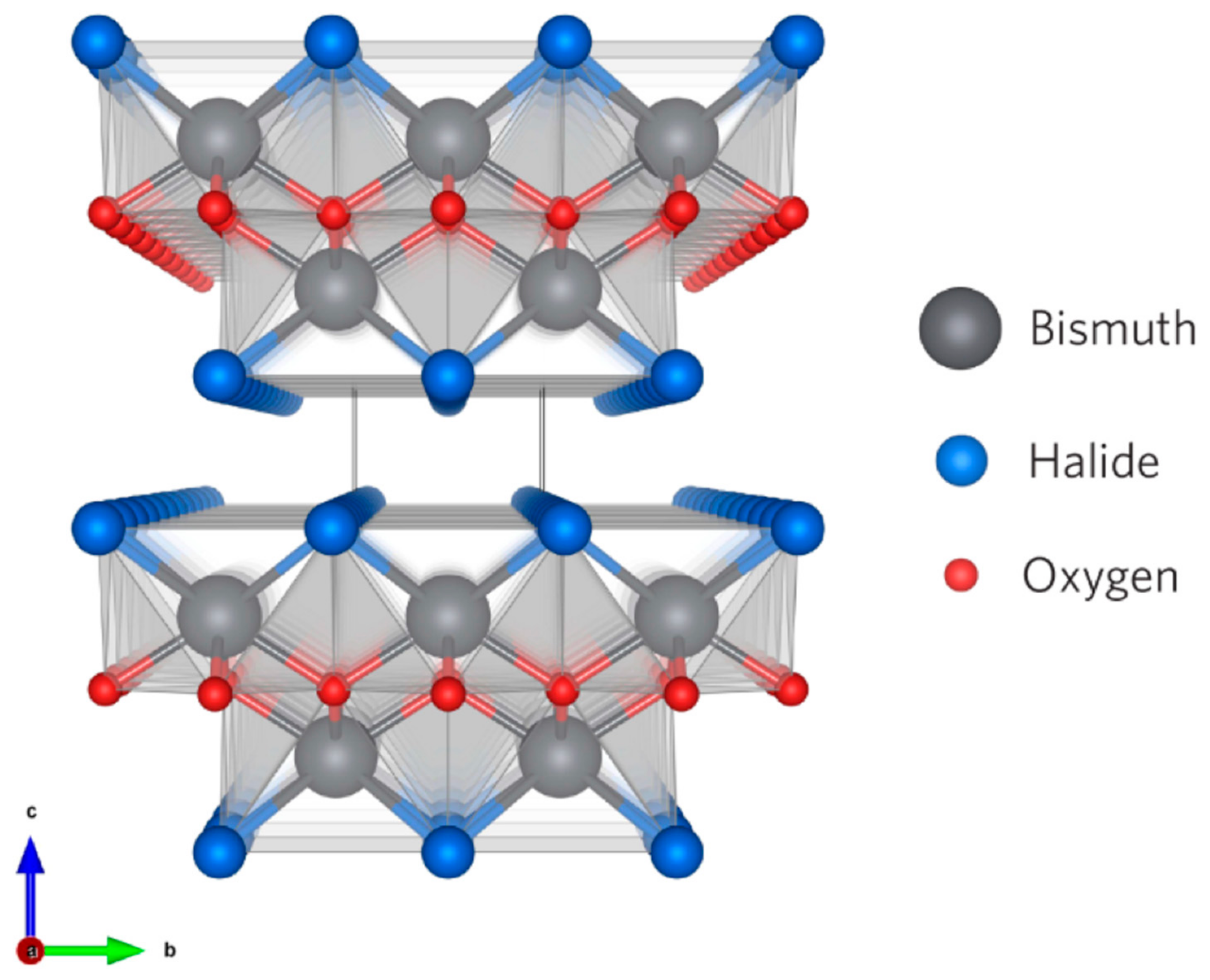
3.1.2. Common Photocatalytic Materials

Photocatalysis necessitates two primary components: photocatalytic semiconductor materials and light illumination. Common photocatalytic materials primarily encompass semiconductor compounds such as TiO2, ZnO, α-Fe2O3, g-C3N4, and bismuth-based compounds, as shown in Table 3. Among these, titanium dioxide (TiO2) exhibits non-toxicity advantages, strong redox potential, and chemical stability, leading to its widespread application. However, its relatively wide bandgap (Eg = 3.2 eV) results in a narrow light response range, primarily responding to ultraviolet (UV) light, thereby limiting its utilization of sunlight and exhibiting a high photogenerated carrier recombination rate [19].
Zinc oxide (ZnO), a traditional semiconductor photocatalytic material, is non-toxic, abundant, and easily obtainable. It possesses excellent photoelectric conversion performance and rapid light response capabilities, making it an optimal material for practical applications in environmental remediation, particularly in the degradation of organic pollutants in water. Nanoscale iron (III) oxide (α-Fe2O3) features a narrow bandgap (Eg = 2.0~2.2 eV), thermodynamic stability, non-toxicity, low cost, acid and alkali resistance, corrosion resistance, and good environmental compatibility. However, its photocatalytic activity is relatively weak when used alone, necessitating composition with other semiconductor materials to enhance its photocatalytic performance.
Graphitic carbon nitride (g-C3N4) belongs to the category of non-metal semiconductor photocatalytic materials. It is chemically stable, exhibits visible light response properties, possesses high photocatalytic active sites and good electron mobility, and is non-toxic and free from heavy metal contamination. Bismuth-based photocatalytic materials, due to the hybridization of O 2p and Bi 6s2 valence bands, exhibit high visible light photocatalytic activity. Among them, BiOX (X = F, Cl, Br, I), with its special lamellar structure as shown in Figure 3, belongs to the tetragonal crystal system and possesses high optical stability, making it a promising class of photocatalytic materials [20].
As a new generation of green, environmentally friendly, and economical materials, semiconductor photocatalytic materials have achieved tremendous success in research and application. However, several challenges remain: (1) Low Photocatalytic Quantum Efficiency: Due to the intrinsic Coulomb interaction of semiconductor materials, photogenerated electron–hole pairs migrating to the material surface recombine within a short period, significantly reducing their photocatalytic efficiency. (2) Low Utilization of Sunlight: Most photocatalytic materials possess wide bandgaps and only respond to UV light, which constitutes only 7% of sunlight. Therefore, the development of narrow bandgap semiconductor materials and the expansion of the visible light response range of wide bandgap materials to improve quantum utilization are urgent issues in current research. (3) Aggregation of Micro/Nanoscale Photocatalytic Materials: The catalytic activity of micro/nanoscale photocatalytic materials is related to their particle size, with smaller particles exhibiting higher catalytic activity. Therefore, photocatalytic materials are mostly in the form of micro/nanoscale particles, which are prone to aggregation during degradation processes. To address this issue, immobilization methods have been proposed.

3.2. Preparation Methods of Fly Ash-Supported Photocatalytic Materials

Literature reviews have revealed that the sol–gel, hydrothermal, and liquid-phase precipitation methods are commonly employed for the preparation of fly ash-based supported photocatalytic materials. Studies have indicated that the synthesis method significantly influences the electronic properties (such as morphology, crystallinity, and size) of the photocatalyst and its photocatalytic activity, as well as the removal mechanism of pollutants. A comparison of these three preparation methods is presented in Table 3.

3.2.1. Sol–Gel Method

The sol–gel method is a process that involves the formation of a solution, sol, gel, followed by drying and subsequent heat treatment to produce nanomaterials. The products prepared using the sol–gel method exhibit high purity, good quality, and ease of loading onto various carriers to form photocatalytic composites. This method offers advantages such as uniform reaction, low production cost, convenient modification, operation at low temperatures, easy control of stoichiometric ratios, and the ability to prepare thin films. Lu et al. [30] prepared TiO2-magnetic Fe3O4/fly ash photocatalytic composites using the sol–gel method and observed their morphology using scanning electron microscopy (SEM), as shown in Figure 4. Figure 4a depicts the spherical morphology (80–120 μm) of the fly ash with a rough surface, and no Fe and Ti elements were detected in the energy dispersive spectroscopy (EDS) elemental analysis. Figure 4b shows the morphology of the synthesized magnetic Fe3O4, which has a uniform size (approximately 250 nm) and spherical structure. Figure 4c presents the TiO2-magnetic Fe3O4/fly ash spheres (100–150 μm) with a relatively smooth and spherical structure. The presence of Fe and Ti elements in the EDS image indicates that TiO2-magnetic Fe3O4 has been successfully coated onto the surface of the floating fly ash spheres. Mühahid et al. [22,31] employed the sol–gel method to immerse porous ceramic samples in 20 mL of Ti-O polymer solution. After heat treatment at 500 °C, TiO2 was uniformly deposited on the surface of the porous ceramics. The average particle size was calculated approximately 98 nm, significantly increasing the surface area of the substrate and further enhancing its photocatalytic activity. However, during the calcination process, the thin film was prone to cracking, leading to agglomeration of the formed grains, which consequently affected the photocatalytic performance.

3.2.2. Hydrothermal Method

The hydrothermal method involves the chemical reaction of reactants in solution under high temperature and pressure conditions, typically occurring within a high-pressure, airtight reactor. In this process, precursors undergo nucleation and growth in the hydrothermal reaction medium, ultimately resulting in the formation of well-crystallized crystals. This method offers advantages such as excellent crystallinity, small size, good dispersion, and controllable crystal morphology. However, it demands specialized equipment, operates under high temperature and pressure conditions, and poses certain potential risks. Yang et al. [32] first pretreated fly ash through alkaline activation, as illustrated in Figure 5. Figure 5a depicts the untreated fly ash microspheres, which exhibit a smooth surface morphology resembling spherical glass beads. After alkaline activation, the growth and deposition of secondary zeolite phases altered the surface, as shown in Figure 5b, resulting in the development of abundant pore structures and the stacking of petal-like microspheres, which significantly enhanced the material’s specific surface area and adsorption capacity. TiO2/fly ash microspheres were prepared using the hydrothermal method, as shown in Figure 5c–e. SEM, High-Resolution Transmission Electron Microscopy (HRTEM), and X-ray Diffraction (XRD) analyses confirmed the formation of TiO2 composed of the anatase phase, with an average particle size of approximately 20 nm and indicated the successful coating of TiO2 nanoparticles on the surface of the fly ash microspheres. Nadeem et al. [27] employed the hydrothermal method to prepare CoFe2O4/fly ash photocatalytic composites. Analysis of the apparent morphology of the materials revealed that the CoFe2O4 particles exhibited an irregular cubic morphology with a rough surface. The composites demonstrated good dispersion, and the incorporation of fly ash improved the fractional size and enhanced the material’s performance.

3.2.3. Liquid-Phase Precipitation Method

The liquid-phase precipitation method involves selecting one or more soluble salts and preparing a solution according to a specific stoichiometric ratio based on the target material to be synthesized. A precipitating agent is then added to induce hydrolysis of the metal salts, resulting in the precipitation of the desired compounds. Subsequently, the precipitate undergoes dehydration or thermal decomposition to produce oxide powders. This method allows for the controlled synthesis of nanomaterials with uniform particle size, small dimensions, and well-defined crystal morphologies.
Lv et al. [33] employed titanium tetrachloride as the titanium source and urea as the precipitating agent to prepare N,S-co-doped TiO2/fly ash bead composites using a hydrolysis-precipitation method, followed by calcination at 500 °C for 2 h. Scanning Electron Microscopy (SEM) analysis of the materials, as shown in Figure 6, revealed that the fly ash beads were hollow with wall thicknesses ranging from 2 to 5 μm. After the hydrolysis-precipitation of the TiO2-loaded fly ash composites, a uniform TiO2 film formed on the surface of the samples. Following calcination at 500 °C for 2 h, fine cracks appeared on the film surface due to the significant difference in thermal expansion coefficients between the TiO2 film and the fly ash beads, resulting in a rougher surface compared to the undoped samples.
Andronic et al. [31] prepared TiO2-CuxS/fly ash ternary heterojunctions using a precipitation method. The resulting samples exhibited uniform particle sizes (200–500 nm) with aggregates of different shapes and sizes distributed on the surface. Energy-Dispersive Spectroscopy (EDS) analysis confirmed that the aggregates were TiO2-CuxS, which were uniformly distributed on the fly ash microspheres, maximizing the specific surface area of the samples and significantly enhancing the photocatalytic activity of the catalysts.

4. Application of Fly Ash-Supported Photocatalytic Materials

4.1. Degradation of Pollutants in Water

Water pollution is a pervasive issue in daily life, stemming primarily from domestic and industrial wastewater, with the latter serving as the primary source. Industrial wastewater contains a myriad of contaminants, including organic chemicals, salts, heavy metals, and radioactive elements, posing significant environmental hazards, particularly to groundwater and surface water resources, and severely impacting the ecosystem. Traditional water treatment methods, such as chemical precipitation, coagulation, and membrane filtration, exhibit certain limitations, including incomplete removal of pollutants and secondary pollution due to the introduction of chemical reagents. Consequently, advanced oxidation processes (AOPs) have been developed for the treatment of water pollutants. Among them, photocatalytic oxidation technology stands out as a typical representative, characterized by its eco-friendliness, thorough treatment, and ability to oxidize pollutants into small molecules like CO2 and H2O, thus gaining widespread application (see Table 4). Recently, fly ash has been reported to possess adsorptive properties, making it a low-cost adsorbent for removing pollutants from water. By integrating fly ash into photocatalytic technology, it simultaneously functions as both an adsorbent and a carrier, enabling the efficient removal of pollutants through the combined use of adsorption and photocatalysis.
Addressing the shortcomings of current photocatalytic technologies, various modification strategies have been employed to enhance the photocatalytic performance of materials, including semiconductor compositing, ion doping, noble metal deposition, photosensitization with sensitizers, and immobilization. Wang et al. [34] modified TiO2 using photosensitization with sensitizers and immobilization techniques, preparing a nano-TiO2-coated fly ash photocatalyst via the sol–gel method. On the one hand, polypyrrole (PPy) was used as a sensitizer for photosensitization, shifting the light response range of TiO2 towards the visible light region, enhancing electron–hole separation, and improving the photocatalytic performance of the material. On the other hand, the inexpensive and non-toxic fly ash spheres, with their rough surfaces, served as the substrate for nano-TiO2 particles, facilitating their dispersion on the surface. Using methylene blue and phenol as target degradants, after three cycles, the degradation efficiency decreased by only about 10%, which reduced aggregation during the reaction process and improved the recycling and regeneration performance of the photocatalytic material.
Kanakaraju et al. [38] modified fly ash with hydrochloric acid, sodium hydroxide, and deionized water, respectively, to load Cu-doped TiO2. As shown in Figure 7a,b, alkaline-modified fly ash exhibited the highest degradation efficiency for methyl orange, reaching 60%, with a removal rate of 30% already achieved at the end of the dark reaction, indicating significant adsorption during the reaction process and demonstrating the synergistic removal effect of adsorption–photocatalysis. Additionally, as shown in Figure 7c, gradual decolorization of methyl orange was observed as the degradation time increased. Furthermore, the light absorption rate of the photocatalyst gradually decreased over time due to the decreasing specific surface area and active sites of fly ash as methyl orange continued to be adsorbed, subsequently leading to reduced photocatalytic activity.

4.2. Degradation of Atmospheric Pollutants

4.2.1. Photocatalytic Degradation of NOx

The emissions from industrial coal combustion, biomass burning, and vehicular exhausts generate substantial quantities of nitrogen oxides (NOx, where x = 1, 2, with NO comprising 95% of the total). NOx serves as a pivotal precursor for the formation of secondary organic aerosols, which can lead to the occurrence of haze, contribute to the formation of acid rain and photochemical smog, and further result in the emission of secondary pollutants such as ozone, posing severe environmental hazards. Additionally, NOx poses strong irritation and damage to human skin and respiratory systems. Figure 8 illustrates a schematic representation of NOx emissions and their environmental impacts.
Currently, common methods for NOx degradation include physical adsorption, selective catalytic reduction (SCR), selective non-catalytic reduction (SNCR), and bio-absorption. However, these methods are primarily applicable to the treatment of high-concentration NOx in industrial waste gases and vehicular exhausts. Photocatalytic oxidation stands out as the most environmentally friendly, economical, and efficient technology for purifying low-concentration NOx in the air. This technique utilizes semiconductor photocatalytic materials to oxidize NOx in the air into non-toxic nitrates, consuming less energy compared to traditional methods and requiring no reductants or fuel gases. Both in terms of economic benefits and treatment efficiency, photocatalysis exhibits high feasibility.
The mechanism of photocatalytic removal of NO from flue gas involves the generation of photogenerated electrons (e−) and holes (h+) through photocatalytic oxidation, as exemplified in Equations (9)–(13). These reactive species, including ·O2, ·OH, and h+, oxidize NO, with NO2 and HNO3 as intermediates, ultimately producing non-toxic NO3−. A previous study prepared TiO2-loaded X-type zeolite using fly ash, where fly ash not only served as the carrier for the photocatalytic material but also participated in the reaction as a porous adsorbent [40,41]. They investigated the degradation effect on NO and achieved a NO removal rate of 75% after 30 min of photoreaction. Furthermore, they analyzed the influence of O2, initial NO concentration, and humidity on the degradation efficiency of NO. The results indicated that the presence of O2 enhanced the photocatalytic degradation efficiency of NO, primarily because O2 captures photogenerated electrons to produce radicals that react with NO. Simultaneously, O2 reacts with NO to generate NO2, and the co-adsorption of NO2 and NO on the catalyst surface significantly improves the NO removal rate. However, as the initial NO concentration and humidity gradually increase, the NO removal rate decreases. When the mass concentration exceeds 1027 mg/m3, the conversion of NO is solely related to the adsorption active sites on the catalyst surface, constituting a zero-order reaction. As humidity increases, the presence of water molecules competes with NO for adsorption on the catalyst surface, thereby affecting the conversion of NO. The application of solid waste in photocatalytic technology promotes the development and application of ecological blocks to address urban air pollution issues.
· O H + N O H N O 2
H N O 2 + · O H N O 2 + H 2 O
N O 2 + · O H H N O 3
N O + 2 H 2 O + 3 h + N O 3 + 4 H +
N O + · O 2 N O 3
Guo et al. [42] applied nano-TiO2 to the surface layer of concrete using mixing and spraying methods, respectively. By comparing the degradation effects of NOx under the two processes, the spray coating method allowed more TiO2 particles to be exposed to the sample surface, making it easier for them to receive ultraviolet (UV) radiation and thus be excited into more reactive substances, thereby achieving better NOx removal performance. Additionally, the study explored the influence of factors such as NO flow rate, initial NO concentration, UV intensity, and relative humidity on the NOx removal rate. Among them, UV intensity had a positive impact on the photocatalytic degradation rate, with the reaction rate increasing as the UV intensity on the catalyst surface increased. Meanwhile, studies have also shown that UV intensity has a similar effect on the degradation of other gaseous pollutants, all positively influencing photocatalytic activity. Xu et al. [42] incorporated TiO2 nanoparticles into fly ash-based concrete to degrade NOx in the atmosphere, achieving a synergistic effect of self-cleaning and air purification.

4.2.2. Photocatalytic Degradation of Volatile Organic Compounds (VOCs)

With the continuous advancement of society and the rapid development of the economy, the extraction and combustion of fossil fuels, vehicle emissions, and household decoration have generated substantial amounts of volatile organic compounds (VOCs), such as alcohols, aldehydes, ketones, olefins, and aromatic hydrocarbon compounds. These compounds pose severe threats to both the environment and human health. Notably, VOCs are not confined to their emission sources but can accumulate in soil, water, and air. Hence, the selection of green and efficient technologies for the degradation of VOCs is imperative.
The integration of adsorption and photocatalysis offers a promising solution. On the one hand, it facilitates the concentration of VOCs on the material surface, enhancing degradation efficiency. On the other hand, through the catalytic activity of photocatalysts, VOCs can be degraded into CO2 and H2O, achieving high removal efficiency at low cost while being environmentally friendly and avoiding secondary pollution. Figure 9 illustrates the mechanism of photocatalytic degradation of VOCs. Porous materials with large specific surface areas, such as activated carbon, graphene, and molecular sieves, are typically chosen as adsorbents to support photocatalytic materials. Xue et al. [43] produced semi-coke activated carbon (SAC) from semi-coke (SC) powder to support g-C3N4-Bi2WO6 photocatalytic composites, leveraging the synergistic effect of adsorption and photocatalysis for VOC degradation. The loading of SAC with a porous surface not only addresses the agglomeration issue of nano-photocatalytic materials during the reaction process, facilitating material recovery, but also reduces the bandgap energy of the photocatalytic composites, broadens the light response range, enhances carrier migration rates, and decreases the recombination rate of photogenerated electrons and holes, as depicted in Figure 10. Gao et al. [44] prepared TiO2-RGO/LDHs photocatalysts using reduced graphene oxide (RGO) and layered double hydroxides (LDHs) as substrates. Under simulated sunlight irradiation, the photocatalytic activity of these materials was evaluated using toluene, methanol, and ethyl acetate as model compounds. RGO expanded the light response range and inhibited the recombination of electron–hole pairs in titanium dioxide. LDHs provided additional hydroxide ions to accelerate the oxidation reaction, enabling better contact and reaction between radicals and pollutants. Currently, there is no research on the use of fly ash as a support for photocatalysts in the degradation of VOCs. However, fly ash, as a porous material with a large specific surface area and strong adsorption properties, can also be employed as an adsorbent in combination with photocatalysts for the synergistic degradation of VOCs, achieving the goal of waste treatment using waste materials.

4.3. Self-Cleaning Properties

In recent years, the design of photocatalytic building materials for self-cleaning, self-disinfection, and environmental pollution remediation has garnered significant attention. Leveraging the advantages of solar energy and rainwater as driving forces, a new frontier has been opened up for environmentally friendly building materials. Currently, the self-cleaning performance of photocatalytic materials is comprehensively evaluated by comparing their photocatalytic degradation efficiency and contact angles. The contact angle serves as an indicator of the wettability of the photocatalytic material surface; a contact angle greater than 90° indicates hydrophobicity, while one less than 90° suggests hydrophilicity. Thirumalai et al. [46] modified ZnO using coal-based solid waste fly ash, employing three dyes—Reactive Orange 4, Rhodamine B, and Trypan Blue—as target degradants to assess the self-cleaning performance of ZnO/fly ash. The mechanism is illustrated in Figure 11.
By comparing the contact angles of four samples, as shown in Figure 12a, the coating prepared with ZnO modified by fly ash exhibited the largest contact angle, reaching 98.9°, indicating a more hydrophobic surface with reduced wettability, contributing to the self-cleaning performance of the photocatalyst. Luévano-Hipólito et al. [47] developed self-cleaning coatings using fly ash and Bi-based photocatalysts. The self-cleaning effect of the photocatalytic coatings was evaluated using methylene blue aqueous solution as the target degradation pollutant. As shown in Figure 12b, the Bi2O2CO3 photocatalytic coating exhibited the best self-cleaning performance on concrete, with a degradation rate reaching 49%. The influence of curing time on the self-cleaning effect was also investigated, as illustrated in Figure 12c. The self-cleaning performance decreased with increasing curing time, primarily due to the absorption or radiation of transition metals in fly ash, which affected the photon mass transfer during the reaction. Additionally, changes in pore structure during the hydration process of the fly ash photocatalytic coating reduced its adsorption capacity for pollutants. However, the self-cleaning performance of the coating could be restored through washing with distilled water. Vega-Mendoza et al. [48] used fly ash as an alternative binder for manufacturing mortar coatings and prepared mortar coatings with α/β-Bi2O3 photocatalysts. Using methylene blue as the degradant, their self-cleaning efficiency was found to reach 31%.

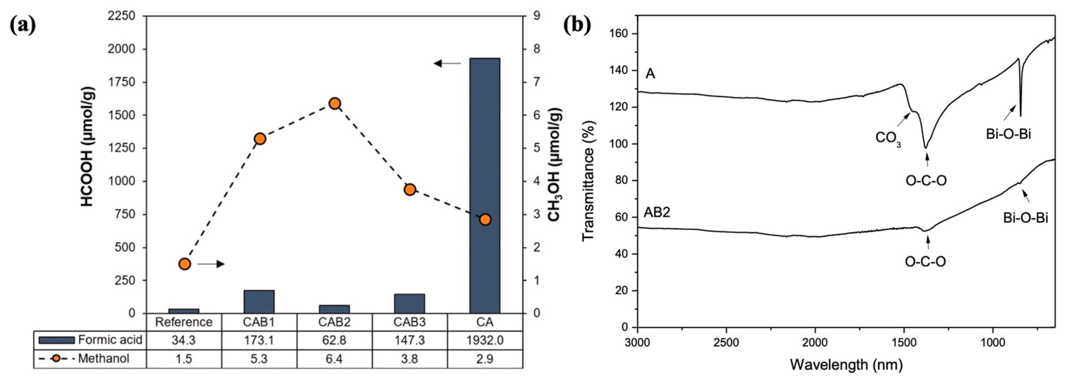
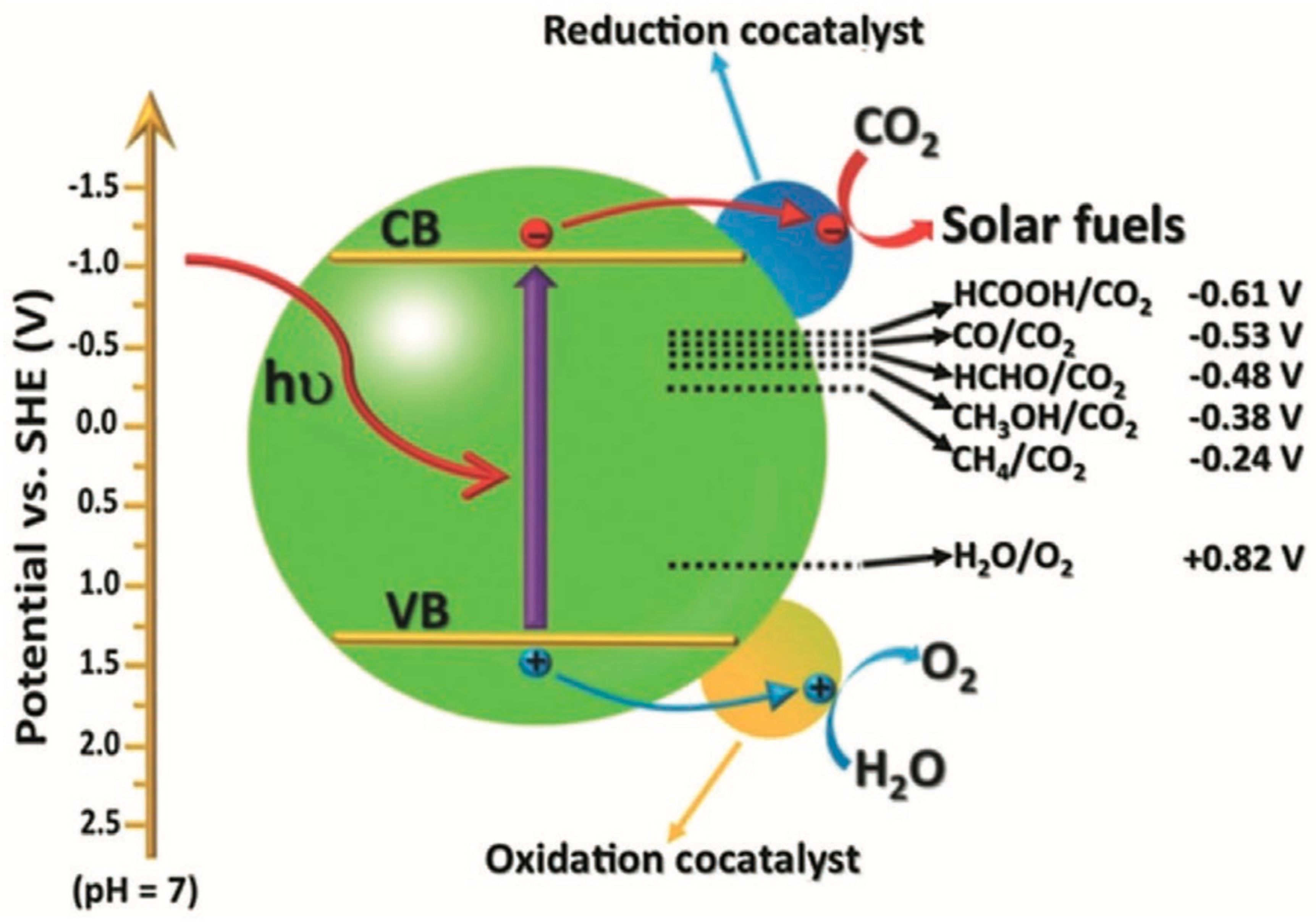
4.4. CO2 Reduction Performance

The escalating emissions of CO2 from the combustion of fossil fuels have exacerbated climate change through the greenhouse effect, making it imperative to enhance the capture and conversion efficiency of CO2. Utilizing sunlight as a driving force to convert CO2 into hydrocarbon fuels such as methanol and methane not only achieves carbon reduction but also provides a means for producing clean energy, thereby realizing sustainable resource utilization. Figure 13 illustrates the mechanism of photocatalytic CO2 conversion. However, single-semiconductor photocatalytic materials suffer from low carrier mobility, high recombination efficiency, and difficulties in recycling. Therefore, loading materials with porous properties is an effective means of modifying photocatalysts. Previous research prepared carbon quantum dots (C-CQDs) using Taixi anthracite coal as a raw material through a chemical oxidation method and loaded them onto g-C3N4 [49]. The addition of C-CQDs caused a redshift in the light response range of g-C3N4, enhancing photocatalytic activity and effectively increasing the yield of methanol synthesized through photocatalytic CO2 reduction, with a maximum of 28.69 μmol/(g·cat), approximately 2.2 times that of pure g-C3N4. Vega-Mendoza et al. [50] prepared α/β-Bi2O3 photocatalytic heterojunctions using three different methods, termed AB1, AB2, and AB3, respectively, with A representing the α-Bi2O3 photocatalyst. Fly ash was used as an alternative binder for manufacturing mortar coatings, and mortar coatings were prepared with α/β-Bi2O3 photocatalysts, termed CAB1, CAB2, CAB3, and CA, respectively.
The CO2 reduction effect of fly ash photocatalytic coatings was investigated. As shown in Figure 14a, with formic acid (HCOOH) and methanol (CH3OH) as the target products, CAB2 exhibited the highest methanol production from CO2 reduction, while CA showed the highest formic acid production. Studies revealed that α-Bi2O3 exhibited higher photocatalytic activity for formic acid production due to its better adsorption of CO2. As shown in the infrared spectrum in Figure 14b, α-Bi2O3 exhibited peaks related to the fixation of CO2 at 1386 cm−1, which are associated with the vibrational modes of carbonates and bicarbonate or carbamate groups, confirming the enhanced production of formic acid through higher CO2 adsorption on the surface of the photocatalytic material. Due to its porous structure, fly ash, when combined with photocatalytic materials in the degradation of pollutants, alleviates the problem of easy agglomeration during the reaction process through the loading of nano-photocatalysts and also increases the adsorption of pollutants, achieving efficient removal of pollutants. Additionally, fly ash contains a large amount of metal/non-metal oxides, which can form intermittent energy levels with photocatalytic materials, reducing bandgap energy and inhibiting the recombination efficiency of photogenerated electron–hole pairs, thereby significantly improving the photocatalytic activity of the material. Furthermore, photocatalytic materials have been incorporated into building materials prepared with fly ash as a filler component, such as concrete, although the effect is limited, and further improvements are needed.
Figure 14. α/β-Bi2O3/fly ash photocatalytic coating for CO2 reduction: (a) α/β-Bi2O3/fly ash photocatalytic coating reduces CO2 to solar fuel; (b) FTIR of the photocatalyst after adsorbing CO2 [51,52].
Crystals 15 00223 g014

5. Conclusions

The utilization of fly ash as a novel carrier for photocatalytic materials adheres to the principles of circular economy and provides a new pathway for the resource recovery of industrial by-products. Starting from the porous nature of fly ash, this paper analyzes the potential of fly ash as a carrier for photocatalysts in the preparation of photocatalytic composites, aiming to modify the photocatalysts through immobilization. Through the analysis of the degradation of pollutants in water, NOx, VOCs, self-cleaning properties, and CO2 reduction performance, it has been demonstrated that the application of fly ash in photocatalytic technology simultaneously fulfills the roles of both carrier and adsorbent. Additionally, fly ash has been used as a filler to prepare building materials with photocatalytic properties, albeit with limited effectiveness. Current research indicates that the incorporation of fly ash can enhance carrier mobility while inhibiting carrier recombination. However, the reaction mechanism remains unclear and requires further exploration using molecular simulation and other techniques. As a catalyst carrier, fly ash possesses a limited number of active sites. Therefore, it is necessary to fully utilize the active substances such as CaO and Fe2O3 in fly ash to improve its catalytic activity. Moreover, the conventional modification techniques for fly ash are not yet mature, resulting in uneven pore structures in the obtained porous fly ash materials. Hence, further research is needed on the modification methods of fly ash. Additionally, current research on fly ash-supported photocatalytic materials is still at the laboratory scale, far from meeting industrial demands. Issues such as low photocatalytic activity and degradation efficiency remain severe, especially in the degradation of gaseous pollutants. Effective modification of photocatalysts can be achieved through the combination of various techniques to further enhance their activity. Furthermore, most of the fly ash-based photocatalytic materials studied at this stage are in powder form. To improve their practical applicability, they could be prepared as practical macroscopic materials such as photocatalytic paints, tiles, mortars, and films.

Author Contributions

C.-G.L., X.-C.Z. and W.-C.L.: Carrying out the Measurements and Experiments, Draft Writing; C.-J.J. and X.-F.C.: Methodology, Reviewing, Project Administration, Funding Acquisition. All authors have read and agreed to the published version of the manuscript.

Funding

This project was funded by the Natural Science Foundation of Fujian under grant number [No. 2023J01999], the General Project of the Fujian Provincial Education and Scientific Research Program for Young and Middle-aged Teachers and Researchers (Social Sciences) [NO. JAS24117]; and the Startup Fund for Advanced Talents of Putian University with grant number [2024051]. Additionally, it received support from the Putian University Zixiao Scholars—Young Top Talent Program-2024 with grant number [2024174], and the Mulan River Comprehensive Governance Research Institute of Putian University with the project [No. ZX2024-12].

Data Availability Statement

The original contributions presented in this study are included in the article. Further inquiries can be directed to the corresponding author(s).

Acknowledgments

Special recognition goes to the Testing Technology Center for Materials and Devices of Tsinghua Shenzhen International Graduate School for their invaluable testing-related services. Also, the authors would like to express their sincere thanks to Wen-Cong Lin from Fujian Nanyu Engineering Construction Co., Ltd., Jian-Sheng Zheng from Fujian Zhongyong Construction Engineering Co., Ltd., and Guo-Hui Yan from Jinxi Holding Group Co., Ltd., all located in Putian 351100, China, for their invaluable assistance and support in the completion of this paper.

Conflicts of Interest

Author Wen-Cong Lin was employed by the company Fujian Nanyu Engineering Construction Co., Ltd. The remaining authors declare that the research was conducted in the absence of any commercial or financial relationships that could be construed as a potential conflict of interest.

References

  1. Jia, Z.; Wen, S.; Sun, Z. Current Relationship between Coal Consumption and the Economic Development and China’s Future Carbon Mitigation Policies. Energy Policy 2022, 162, 112812. [Google Scholar] [CrossRef]
  2. Chen, X.-F.; Jiao, C.-J. A Photocatalytic Mortar Prepared by Tourmaline and TiO2 Treated Recycled Aggregates and Its Air-Purifying Performance. Case Stud. Constr. Mater. 2022, 16, e01073. [Google Scholar] [CrossRef]
  3. Chen, X.-F.; Lin, S.-R.; Kou, S.-C. Effect of Composite Photo-Catalysts Prepared with Recycled Clay Brick Sands and Nano-TiO2 on Methyl Orange and NOx Removal. Constr. Build. Mater. 2018, 171, 152–160. [Google Scholar] [CrossRef]
  4. Ahmed, E.-S.A.E.; El-Sayed, B.A.; Mohamed, W.A.A.; Fahmy, A.; Helal, A. Recycling of Supported Nanocomposites for Hazardous Industrial Wastewater Treatment via Solar Photocatalytic Process. Egypt. J. Pet. 2021, 30, 29–35. [Google Scholar] [CrossRef]
  5. Wang, C.; Xu, G.; Gu, X.; Gao, Y.; Zhao, P. High Value-Added Applications of Coal Fly Ash in the Form of Porous Materials: A Review. Ceram. Int. 2021, 47, 22302–22315. [Google Scholar] [CrossRef]
  6. Sarbak, Z.; Kramer-Wachowiak, M. Porous Structure of Waste Fly Ashes and Their Chemical Modifications. Powder Technol. 2002, 123, 53–58. [Google Scholar] [CrossRef]
  7. Humayun, M.; Wang, C.; Luo, W. Recent Progress in the Synthesis and Applications of Composite Photocatalysts: A Critical Review. Small Methods 2022, 6, 2101395. [Google Scholar] [CrossRef]
  8. Paumo, H.K.; Tufa, L.T.; Gicha, B.B.; Molla, C.F.; Nguyen, H.; Tran, V.T.; Nwaji, N.; Hu, X.; Chen, H.; Lee, J. Plasmon-Enhanced Photo/Electrocatalysis: Harnessing Hetero-Nanostructures for Sustainable Energy and Environmental Applications. Appl. Phys. Rev. 2024, 11, 041336. [Google Scholar] [CrossRef]
  9. Mathapati, M.; Amate, K.; Durga Prasad, C.; Jayavardhana, M.L.; Hemanth Raju, T. A Review on Fly Ash Utilization. Mater. Today Proc. 2022, 50, 1535–1540. [Google Scholar] [CrossRef]
  10. Chen, X.-F.; Quan, C.-Q.; Jiao, C.-J. Experimental Study of Chloride Resistance of Polypropylene Fiber Reinforced Concrete with Fly Ash and Modeling. Materials 2021, 14, 4417. [Google Scholar] [CrossRef]
  11. Wang, D.; Shen, X.; Wang, Z.; Zhang, X.; Chen, X.-F. Effect of Quicklime Substitution for Cement on the Physical and Mechanical Properties of Autoclaved Fly Ash Aggregates via Hydrothermal Synthesis. Materials 2025, 18, 707. [Google Scholar] [CrossRef] [PubMed]
  12. Song, W.; Song, H.; Fan, Z. Research progress of fly ash in anticorrosive coatings. Prog. Chem. Ind. 2023, 42, 4894–4904. [Google Scholar]
  13. Yadav, V.K.; Gnanamoorthy, G.; Cabral-Pinto, M.M.S.; Alam, J.; Ahamed, M.; Gupta, N.; Singh, B.; Choudhary, N.; Inwati, G.K.; Yadav, K.K. Variations and Similarities in Structural, Chemical, and Elemental Properties on the Ashes Derived from the Coal Due to Their Combustion in Open and Controlled Manner. Environ. Sci. Pollut. Res. 2021, 28, 32609–32625. [Google Scholar] [CrossRef]
  14. Zhang, W.; Wang, S.; Ran, J.; Lin, H.; Kang, W.; Zhu, J. Research Progress on the Performance of Circulating Fluidized Bed Combustion Ash and Its Utilization in China. J. Build. Eng. 2022, 52, 104350. [Google Scholar] [CrossRef]
  15. Hussain, Z.; Chang, N.; Sun, J.; Xiang, S.; Ayaz, T.; Zhang, H.; Wang, H. Modification of Coal Fly Ash and Its Use as Low-Cost Adsorbent for the Removal of Directive, Acid and Reactive Dyes. J. Hazard. Mater. 2022, 422, 126778. [Google Scholar] [CrossRef]
  16. Orczykowski, W.; Bieliński, D.M.; Anyszka, R.; Pędzich, Z. Fly Ash from Lignite Combustion as a Filler for Rubber Mixes. Part I: Physical Valorization of Fly Ash. Materials 2022, 15, 4869. [Google Scholar] [CrossRef]
  17. Deng, X.; Qi, L.; Zhang, Y. Experimental Study on Adsorption of Hexavalent Chromium with Microwave-Assisted Alkali Modified Fly Ash. Water Air Soil Pollut. 2018, 229, 18. [Google Scholar] [CrossRef]
  18. Chakravorty, A.; Roy, S. A Review of Photocatalysis, Basic Principles, Processes, and Materials. Sustain. Chem. Environ. 2024, 8, 100155. [Google Scholar] [CrossRef]
  19. Kudo, A.; Miseki, Y. Heterogeneous Photocatalyst Materials for Water Splitting. Chem. Soc. Rev. 2009, 38, 253–278. [Google Scholar] [CrossRef]
  20. Ganose, A.M.; Cuff, M.; Butler, K.T.; Walsh, A.; Scanlon, D.O. Interplay of Orbital and Relativistic Effects in Bismuth Oxyhalides: BiOF, BiOCl, BiOBr, and BiOI. Chem. Mater. 2016, 28, 1980–1984. [Google Scholar] [CrossRef] [PubMed]
  21. Wang, B.; Li, Q.; Wang, W.; Li, Y.; Zhai, J. Preparation and Characterization of Fe3+-Doped TiO2 on Fly Ash Cenospheres for Photocatalytic Application. Appl. Surf. Sci. 2011, 257, 3473–3479. [Google Scholar] [CrossRef]
  22. Chen, X.-F.; Jiao, C.-J. Effect of Physical Properties of Construction Wastes Based Composite Photocatalysts on the Sulfur Dioxide Degradation: Experimental Investigation and Mechanism Analysis. Case Stud. Constr. Mater. 2022, 17, e01237. [Google Scholar] [CrossRef]
  23. Özcan, M.; Birol, B.; Kaya, F. Investigation of Photocatalytic Properties of TiO2 Nanoparticle Coating on Fly Ash and Red Mud Based Porous Ceramic Substrate. Ceram. Int. 2021, 47, 24270–24280. [Google Scholar] [CrossRef]
  24. Lin, L.; Huang, M.; Chen, D. BiOBr/BiOI Photocatalyst Based on Fly Ash Cenospheres with Improved Photocatalytic Performance. Molecules 2016, 21, 666. [Google Scholar] [CrossRef]
  25. Zhang, X.; Chen, W.; Lin, W.; Zheng, J.; Yan, G.; Chen, X. Enhanced Photocatalytic Activity in Photocatalytic Concrete: Synthesis, Characterization, and Comprehensive Performance Assessment of Nano-TiO2-Modified Recycled Aggregates. Catalysts 2024, 14, 711. [Google Scholar] [CrossRef]
  26. Wang, Z.; Luan, D.; Madhavi, S.; Hu, Y.; Lou, X.W.D. Assembling Carbon-Coated α-Fe2O3 Hollow Nanohorns on the CNT Backbone for Superior Lithium Storage Capability. Energy Environ. Sci. 2012, 5, 5252–5256. [Google Scholar] [CrossRef]
  27. Chen, X.-F.; Chen, W.-Z.; Zhang, X.-C.; Lin, W.-C.; Zheng, J.-S.; Yan, G.-H. Nano-TiO2-Enhanced Surface Functionalization of Recycled Concrete Aggregates for Improved Degradation Efficiency of Low-Concentration Sulfur Dioxide. Catalysts 2024, 14, 709. [Google Scholar] [CrossRef]
  28. Nadeem, N.; Yaseen, M.; Rehan, Z.A.; Zahid, M.; Shakoor, R.A.; Jilani, A.; Iqbal, J.; Rasul, S.; Shahid, I. Coal Fly Ash Supported CoFe2O4 Nanocomposites: Synergetic Fenton-like and Photocatalytic Degradation of Methylene Blue. Environ. Res. 2022, 206, 112280. [Google Scholar] [CrossRef]
  29. Li, X.; Han, J.; Liu, Y.; Dou, Z.; Zhang, T. Summary of Research Progress on Industrial Flue Gas Desulfurization Technology. Sep. Purif. Technol. 2022, 281, 119849. [Google Scholar] [CrossRef]
  30. Shi, T.; Hao, X.; Ma, J.; Liu, H.; Gai, G.; Zhang, Y. Preparation of Ag2O/TiO2/Fly-Ash Cenospheres Composite Photocatalyst. Mater. Lett. 2016, 183, 444–447. [Google Scholar] [CrossRef]
  31. Lu, Z.; Zhou, W.; Huo, P.; Luo, Y.; He, M.; Pan, J.; Li, C.; Yan, Y. Performance of a Novel TiO2 Photocatalyst Based on the Magnetic Floating Fly-Ash Cenospheres for the Purpose of Treating Waste by Waste. Chem. Eng. J. 2013, 225, 34–42. [Google Scholar] [CrossRef]
  32. Andronic, L.; Isac, L.; Cazan, C.; Enesca, A. Simultaneous Adsorption and Photocatalysis Processes Based on Ternary TiO2–CuxS–Fly Ash Hetero-Structures. Appl. Sci. 2020, 10, 8070. [Google Scholar] [CrossRef]
  33. Yang, L.; Wang, F.; Hakki, A.; Macphee, D.E.; Liu, P.; Hu, S. The Influence of Zeolites Fly Ash Bead/TiO2 Composite Material Surface Morphologies on Their Adsorption and Photocatalytic Performance. Appl. Surf. Sci. 2017, 392, 687–696. [Google Scholar] [CrossRef]
  34. Chen, X.-F.; Kou, S.-C. Sulfur Dioxide Degradation by Composite Photocatalysts Prepared by Recycled Fine Aggregates and Nanoscale Titanium Dioxide. Nanomaterials 2019, 9, 1533. [Google Scholar] [CrossRef]
  35. Chen, X.-F.; Jiao, C.-J. Effect of Construction Wastes on the Rheo-Physical Behavior of Photocatalytic Mortar. Case Stud. Constr. Mater. 2022, 16, e01049. [Google Scholar] [CrossRef]
  36. Wu, M.-C.; Wu, P.-Y.; Lin, T.-H.; Lin, T.-F. Photocatalytic Performance of Cu-Doped TiO2 Nanofibers Treated by the Hydrothermal Synthesis and Air-Thermal Treatment. Appl. Surf. Sci. 2018, 430, 390–398. [Google Scholar] [CrossRef]
  37. Patil, B.P.; Jayaram, R. V Photocatalytic Degradation of Reactive Dyes Using Flyash Supported Ag-TiO2 Photocatalysts. ChemistrySelect 2022, 7, e202104183. [Google Scholar] [CrossRef]
  38. Chuaicham, C.; Inoue, T.; Balakumar, V.; Tian, Q.; Ohtani, B.; Sasaki, K. Visible Light-Driven ZnCr Double Layer Oxide Photocatalyst Composites with Fly Ashes for the Degradation of Ciprofloxacin. J. Environ. Chem. Eng. 2022, 10, 106970. [Google Scholar] [CrossRef]
  39. Kanakaraju, D.; bin Ya, M.H.; Lim, Y.-C.; Pace, A. Combined Adsorption/Photocatalytic Dye Removal by Copper-Titania-Fly Ash Composite. Surf. Interfaces 2020, 19, 100534. [Google Scholar] [CrossRef]
  40. Antenozio, M.L.; Caissutti, C.; Caporusso, F.M.; Marzi, D.; Brunetti, P. Urban Air Pollution and Plant Tolerance: Omics Responses to Ozone, Nitrogen Oxides, and Particulate Matter. Plants 2024, 13, 2027. [Google Scholar] [CrossRef]
  41. Supelano García, I.; Palacio Gómez, C.A.; Weber, M.H.; Saavedra Gaona, I.M.; Castañeda Martínez, C.P.; Martínez Zambrano, J.J.; Rojas Sarmiento, H.A.; Munevar Cagigas, J.A.; Avila, M.A.; Rettori, C.; et al. Physicochemical Properties of Ti3+ Self-Doped TiO2 Loaded on Recycled Fly-Ash Based Zeolites for Degradation of Methyl Orange. Condens. Matter 2022, 7, 69. [Google Scholar] [CrossRef]
  42. Guo, M.-Z.; Ling, T.-C.; Poon, C.S. Photocatalytic NOx Degradation of Concrete Surface Layers Intermixed and Spray-Coated with Nano-TiO2: Influence of Experimental Factors. Cem. Concr. Compos. 2017, 83, 279–289. [Google Scholar] [CrossRef]
  43. Xu, M.; Clack, H.; Xia, T.; Bao, Y.; Wu, K.; Shi, H.; Li, V. Effect of TiO2 and Fly Ash on Photocatalytic NOx Abatement of Engineered Cementitious Composites. Constr. Build. Mater. 2020, 236, 117559. [Google Scholar] [CrossRef]
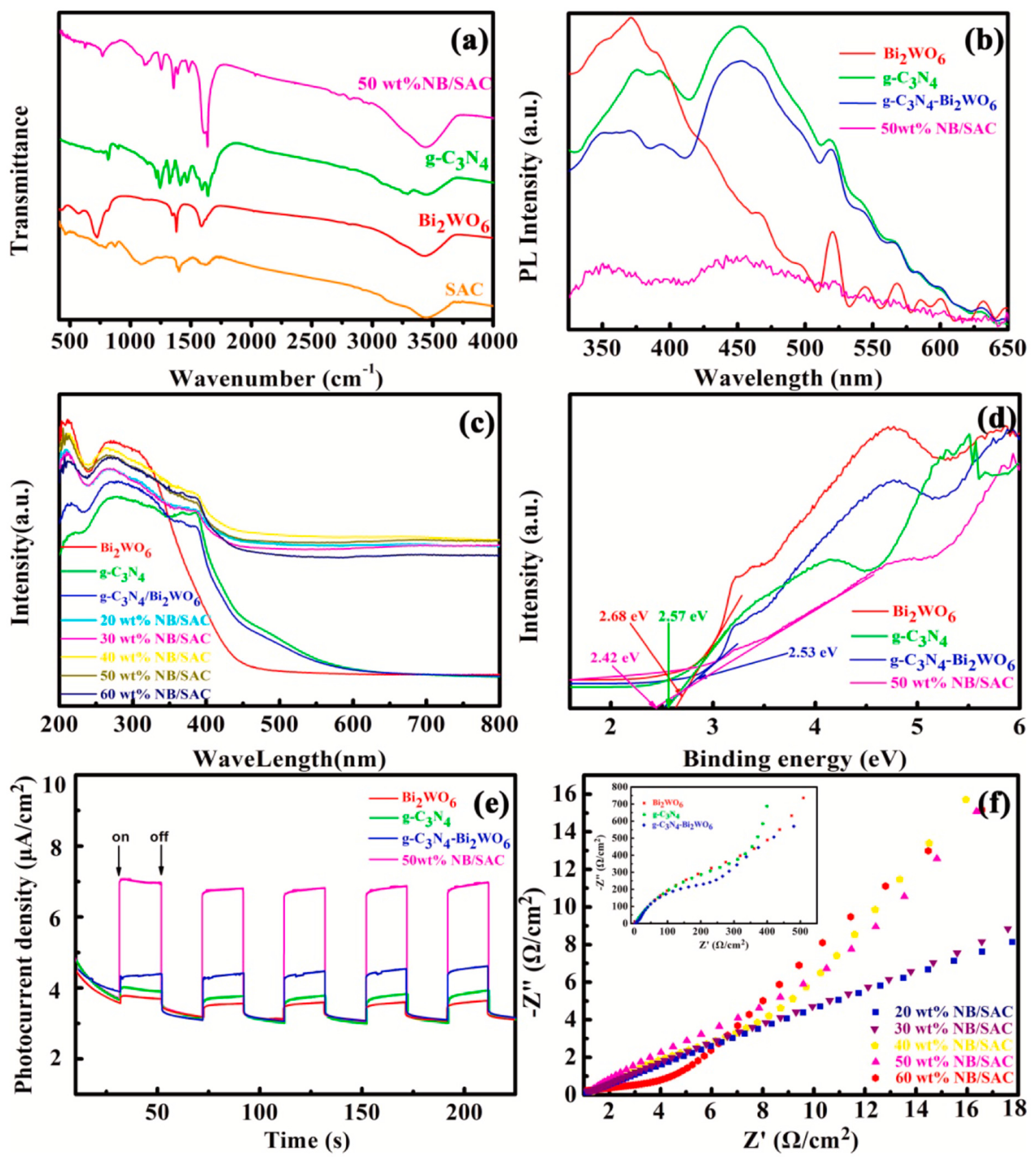
  44. Xue, J.; Shi, L.; Wang, P.; Cheng, W.; Long, M.; Sheng, M.; Bi, Q. Efficient Degradation of VOCs Using Semi-Coke Activated Carbon Loaded 2D Z-Scheme g-C3N4-Bi2WO6 Photocatalysts Composites under Visible Light Irradiation. Sep. Purif. Technol. 2023, 305, 122535. [Google Scholar] [CrossRef]
  45. Gao, X.; Zheng, K.; Zhang, Q.; Cao, X.; Wu, S.; Su, J. Self-Assembly TiO2-RGO/LDHs Nanocomposite: Photocatalysis of VOCs Degradation in Simulation Air. Appl. Surf. Sci. 2022, 586, 152882. [Google Scholar] [CrossRef]
  46. Shayegan, Z.; Lee, C.-S.; Haghighat, F. TiO2 Photocatalyst for Removal of Volatile Organic Compounds in Gas Phase—A Review. Chem. Eng. J. 2018, 334, 2408–2439. [Google Scholar] [CrossRef]
  47. Thirumalai, K.; Balachandran, S.; Swaminathan, M. Superior Photocatalytic, Electrocatalytic, and Self-Cleaning Applications of Fly Ash Supported ZnO Nanorods. Mater. Chem. Phys. 2016, 183, 191–200. [Google Scholar] [CrossRef]
  48. Luévano-Hipólito, E.; Torres-Martínez, L.M.; Cantú-Castro, L.V.F. Self-Cleaning Coatings Based on Fly Ash and Bismuth-Photocatalysts: Bi2O3, Bi2O2CO3, BiOI, BiVO4, BiPO4. Constr. Build. Mater. 2019, 220, 206–213. [Google Scholar] [CrossRef]
  49. Chen, X.; Zhang, X.; Chen, W.-Z. Advanced Predictive Modeling of Concrete Compressive Strength and Slump Characteristics: A Comparative Evaluation of BPNN, SVM, and RF Models Optimized via PSO. Materials 2024, 17, 4791. [Google Scholar] [CrossRef]
  50. Guo, J.; Fan, Y.; Qiao, C.; Ma, X.; Dong, X.; Zeng, H. Harnessing Coal and Coal Waste for Environmental Conservation: A Review of Photocatalytic Materials. Sci. Total Environ. 2024, 946, 174437. [Google Scholar] [CrossRef]
  51. Vega-Mendoza, M.S.; Luévano-Hipólito, E.; Torres-Martínez, L.M. Design and Fabrication of Photocatalytic Coatings with α/β-Bi2O3 and Recycled-Fly Ash for Environmental Remediation and Solar Fuel Generation. Ceram. Int. 2021, 47, 26907–26918. [Google Scholar] [CrossRef]
  52. Guo, R.; Wang, J.; Bi, Z.; Chen, X.; Hu, X.; Pan, W. Recent Advances and Perspectives of Core-Shell Nanostructured Materials for Photocatalytic CO2 Reduction. Small 2023, 19, 2206314. [Google Scholar] [CrossRef] [PubMed]
Figure 1. Band structure distribution of semiconductors [19].
Crystals 15 00223 g001
Figure 2. Mechanism diagram of semiconductor photocatalysis.
Crystals 15 00223 g002
Figure 3. Schematic diagram of the crystal structure of BiOX (X = F, Cl, Br, I) [20].
Crystals 15 00223 g003
Figure 4. SEM diagram and EDS of TiO2-magnetic Fe3O4/fly ash photocatalytic composites: (a) Schematic diagram of the morphology of coal fly ash and EDS; (b) Schematic diagram of the morphology of magnetic Fe3O4 and EDS; (c) Schematic diagram of the morphology of spherical TiO2-magnetic Fe3O4/coal fly ash and EDS [30].
Crystals 15 00223 g004
Figure 5. TiO2/zeolite fly ash microbeads: (a) SEM image of fly ash microspheres; (b) SEM image of alkali-activated fly ash microspheres; (c) SEM image of TiO2/alkali-activated fly ash microspheres; (d) HRTEM image of TiO2/alkali-activated fly ash microspheres; (e) XRD pattern of TiO2/alkali-activated fly ash microspheres; (f) relative intensity [32].
Crystals 15 00223 g005
Figure 6. SEM diagram of N, S co-doped TiO2/fly ash: (a) fly ash; (b) fly ash loaded with TiO2; (c) TiO2/coal fly ash calcined at 500 °C; (d) N, S co-doped TiO2/coal fly ash [33].
Crystals 15 00223 g006
Figure 7. Degradation efficiency of Cu–TiO2/Fly Ash Photocatalyst: (a) Photocatalytic degradation of methyl orange by Cu–TiO2/coal fly ash under UV light; (b) Photocatalytic degradation of methyl orange by Cu–TiO2/coal fly ash under UV light under visible light irradiation; (c) UV–Vis spectra evolution of methyl orange degradation with base-FA/Cu/TiO2 photocatalyst [38].
Crystals 15 00223 g007
Figure 8. Schematic diagram of NOx emissions and environmental impact [39].
Crystals 15 00223 g008
Figure 9. Reaction mechanism of photocatalytic degradation of VOCs [45].
Crystals 15 00223 g009
Figure 10. g-C3N4-Bi2WO6/SAC photocatalyst: (a) FT-IR spectra of 50 wt% NB/SAC, SAC, pure g-C3N4, and Bi2WO6. (b) Photoluminescence spectra. (c) UV–Vis diffuse reflectance spectra. (d) Evaluation of the band gap through the linear dependence of (Ahν)2 versus hν. (e) Photocurrent response of g-C3N4, Bi2WO6, g-C3N4-Bi2WO6, and 50 wt% NB/SAC samples. (f) EIS Nyquist plots [43].
Crystals 15 00223 g010
Figure 11. Mechanism diagram of photocatalytic self-cleaning reaction of ZnO/fly ash [46].
Crystals 15 00223 g011
Figure 12. Fly ash photocatalytic self-cleaning coating: (a) the contact angle of different samples; (b) the self-cleaning efficiency of the photocatalytic coating after 3 h of irradiation; (c) The self-cleaning efficiency at different curing times [46,47].
Crystals 15 00223 g012
Figure 13. Mechanism diagram of photocatalytic conversion of CO2 [50].
Crystals 15 00223 g013
Table 1. Primary physical properties of fly ash-based cementitious materials [12].
ParametersRangesAverage Values
Density/g·cm−31.9–2.92.1
Standard Consistency of Raw Ash/%27.3–66.748
Water Requirement/%89–130106
28-day Compressive Strength Ratio/%37–8566
Table 3. Comparison of Preparation Methods of Photocatalytic Materials.
Preparation MethodPhotocatalytic MaterialsTarget Degradation SubstancesDegradation EfficiencyAdvantages and DisadvantagesRef.
Sol-gel MethodFe3⁺–TiO2/coal fly ashMethylene BlueThe degradation rate increases by about 30% after adding coal fly ash.The reaction is simple and easy to control; the reaction is uniform; the film is prone to cracking; easy to agglomerate.[20]
TiO2–magnetic Fe3O4/coal fly ash microspheresEnrofloxacin Hydrochloride75.32% in 60 min.[21,22]
TiO2/coal fly ash porous ceramicsMethylene BlueAbout 50% in 240 min.
BiOBr–BiOI/coal fly ash-99% in 70 min.[23]
Cu–TiO2/coal fly ashMethyl Orange99.1% under visible light in 2 h; complete degradation under ultraviolet light.[24]
Hydrothermal MethodTiO2/coal fly ash beadsRhodamine B99% in 90 min.The sample has good properties (good crystallinity, small size, good dispersibility); the crystal form of particles can be controlled; high temperature and high pressure are required.[25]
ZnO/coal fly ashNitrogen Dye Active Orange 4, Rhodamine B, and Trypan Blue98% in 90 min.[26]
CoFe2O4/coal fly ashMethylene Blue99% in 60 min.[27]
TiO2/coal fly ash-based X–zeoliteNO75% in 60 min.[27]
Liquid-phase Precipitation MethodZnCr-layered double oxide/coal fly ashCiprofloxacin98% in 120 min.The preparation method is simple; the sample composition is uniform.[17]
N, S co-doped TiO2/coal fly ash microspheresMethyl Orange65% in 60 min.[28]
Ag2O–TiO2/FACsMethylene Blue100% in 30 min.[29]
TiO2–Cu4S/coal fly ashMethylene Blue99% in 360 min.
Table 4. Photocatalytic degradation of pollutants in water.
Photocatalytic MaterialsLight SourcePreparation MethodTarget Degradation Substances and Degradation EfficiencyRef.
PPy–TiO2/coal fly ashVisible lightSol–gel methodMethylene blue; 75% in 5 h, and still maintains about 70% after 4 cycles[34]
Cu–TiO2/coal fly ashUV/Visible lightSol–gel methodMethyl orange; 99.1% under visible light in 2 h, and complete degradation under UV light[24]
BiOBr–BiOI/coal fly ashBlue LED lightHydrothermal methodRhodamine B; 99% in 70 min, and still reaches 90% after 5 cycles[35]
Ag–TiO2/coal fly ashVisible lightSol–gel methodActive dyes; 85–95% in 3–4 h[36]
TiO2/coal fly ash microspheresVisible lightHydrothermal methodRhodamine B; 99% in 90 min[26]
ZnCr-layered double oxides/coal fly ashSimulated sunlightSimple precipitation methodCiprofloxacin; 98% in 120 min[37]
Disclaimer/Publisher’s Note: The statements, opinions and data contained in all publications are solely those of the individual author(s) and contributor(s) and not of MDPI and/or the editor(s). MDPI and/or the editor(s) disclaim responsibility for any injury to people or property resulting from any ideas, methods, instructions or products referred to in the content.

