Article

Regulating the Mechanical and Corrosion Properties of Mg-2Zn-0.1Y Alloy by Trace SiC with Different Morphologies

1
College of Materials Science and Engineering, Taiyuan University of Technology, Taiyuan 030024, China
2
Shanxi Key Laboratory of Magnesium Matrix Materials, Taiyuan University of Technology, Taiyuan 030024, China
*
Author to whom correspondence should be addressed.
Crystals 2025, 15(2), 166; https://doi.org/10.3390/cryst15020166
Submission received: 17 January 2025 / Revised: 1 February 2025 / Accepted: 4 February 2025 / Published: 8 February 2025
(This article belongs to the Special Issue Microstructure and Mechanical Properties of Alloys and Composites)

Abstract

:
Traditional magnesium structural materials are used widely due to their light weight; however, their corrosion resistance is poor. In order to address this problem and improve the strength simultaneously, SiCp-, SiCnp-, and SiCnw-reinforced Mg-2Zn-0.1Y (wt. %, MZY alloy) matrix composites (SiC/MZY composites) with the same contents (0.3 wt. %) were prepared and extruded at low temperature in this paper. The effects of SiC morphology on the microstructure, mechanical properties and corrosion resistance of MZY alloy were studied. The results show that the grain size can be refined by adding SiC reinforcement. Compared with the unreinforced MZY alloy, the strengths of the SiC/MZY composites were all improved, with a yield strength of more than 440 MPa and an ultimate tensile strength of more than 450 MPa. However, only the corrosion rate of the composites reinforced by submicron SiCp was improved significantly. The hydrogen evolution corrosion rate (PH) was reduced by 81% relative to the MZY alloy. This can be attributed to the decreased galvanic corrosion pairs, as well as the decreased potential difference between the second phase and the matrix in the SiCp/MZY composite. Additionally, a compact product film on the surface of the SiCp/MZY composite can also protect the matrix. The materials prepared in this study showed excellent strength and high corrosion resistance at relatively low cost, providing valuable insights and design ideas for the development and application of those materials in marine and offshore engineering applications.

1. Introduction

As the lightest metal structural material, Mg is widely used in the fields of transport and aerospace [1,2,3,4,5,6,7]. However, pure magnesium has poor mechanical properties and poor corrosion resistance in high-humidity or high-Cl-content environments. Its poor mechanical properties and corrosion resistance limit its industrial applications [8,9,10,11,12,13,14]. Its mechanical properties can be improved by alloying [15,16], while the corrosion resistance of Mg alloys is extremely poor, due to the large potential difference between the magnesium matrix and second phase. Therefore, how to achieve the simultaneous improvement of mechanical and corrosion properties is an urgent problem. As a common alloy, Mg–Zn alloy is inexpensive. Meanwhile, it is known that the addition of Zn can improve the mechanical properties and corrosion resistance of magnesium alloys, according to related research [17,18,19,20]. However, excessive Y content results in the presence of a great number of second phases in Mg–Zn–Y alloy, which is detrimental to corrosion resistance. Therefore, this study prepared an Mg-2Zn-0.1Y alloy by adding a low content of Zn (2 wt. %) and trace amounts of Y (0.1 wt. %). To refine the grains and increase the strength, the alloy was extruded at a low temperature.
The addition of reinforcements to alloys is an important method of modulating the microstructure to improve mechanical properties. Numerous studies [21,22,23,24,25] have shown that the addition of reinforcements improves the mechanical properties generally. As a commonly used reinforcement, SiC has a significant effect on the strength of composites; however, there are no systematic findings on its effect on corrosion performance. Sagar et al. [26] found that the corrosion rate of the composite with 15% SiC and 0.5% AlN particles in ZK60 was lower than that of the alloy, which was mainly due to the formation of a Si–O-rich surface film. Li et al. [27] found an increase of an order of magnitude in the corrosion current density with the addition of micron SiC, attributed to the increase in the number of interfaces caused by the addition of particles and the entrance of the corrosive solution. Singla et al. [28] found a decrease in the corrosion rate with the addition of nano-SiC to WE43, which is in accordance with the findings of Zakaria [29]. Zakaria found that reducing the size of SiC is favorable to corrosion rate reduction at room temperature. However, Esmaily et al. [30] found that a larger size of SiC is more favorable for corrosion resistance. Velavan et al. [31] also found that the addition of micron SiC particles improves the corrosion resistance of AZ61 due to the fact that SiC particles can prevent the migration of Mg2+ ions. According to the current study, the differences in the effects of SiC on corrosion performance are mainly due to the following reasons. SiC is beneficial to the formation of a dense surface film, and thus reduces the corrosion rate; however, the agglomeration of the reinforcement and the change of the second phase due to the difference in size and content leads to a change in the corrosion rate. Zhou et al. [32] added SiCnw to the coating and found that, benefiting from the unique morphology, the addition of SiCnw could prevent the corrosion solution from intruding effectively, thus reducing the corrosion rate. In summary, the sizes and morphologies of SiC reinforcements affect the corrosion performance of composites. However, there is no systematic study on the influence mechanism of SiC reinforcements with different morphologies and sizes on the corrosion performance of magnesium matrix composites.
Therefore, in this paper, the ultrasound-assisted semi-solid stir method was used to add three trace amounts (0.3 wt. %) of SiC reinforcements with different morphologies to Mg-2Zn-0.1Y (wt. %, MZY) alloy. The composites (SiCp/MZY, SiCnp/MZY, SiCnw/MZY) were prepared using submicron silicon carbide particles (SiCp, 0.5–0.7 μm), silicon carbide nanoparticles (SiCnp, 50–60 nm), and silicon carbide nanowires (SiCnw; D, 30–50 nm and L, 1–5 μm), respectively. This research aims to provide a new idea for developing magnesium matrix composites that achieve simultaneous improvements in mechanical and corrosion properties.

2. Experimental Procedures

2.1. Materials Preparation

The Mg-2Zn-0.1Y (wt. %) matrix alloy was composed of pure Mg (99.98%), pure Zn particles (99.999%), and Mg-30 wt. % Y master alloy. The three SiC reinforcements were submicron SiC particles (SiCp), SiC nanoparticles (SiCnp), and SiC nanowires (SiCnw). The compositions of the alloy and composites are shown in Table 1. The preparation process of the composites is shown in Figure 1. Firstly, pure Mg was melted at 750 °C. The melt was then cooled to 720 °C, at which point it was combined with pure Zn particles and the Mg–Y alloy. Following this, 0.3 wt. % SiC was added via semi-solid stirring. The melting was conducted under mixed CO2 and SF6 gases to prevent oxidation. After stirring for 10 min and ultrasonication for 10 min, the melt was cooled to 710 °C and then poured into a preheated steel mold. The composites (SiC/MZY) were produced using a pressure casting process. Before extrusion, the as-cast alloy and composites had to be homogenized (400 °C/8 h). The clean extruded blocks (30 mm × 30 mm × 60 mm) were then heated for 30 min and extruded into ϕ10 mm rods. The extrusion temperature was set as 140 °C, while the extrusion speed was set as 0.1 mm/s.

2.2. Microstructure Characterization

The observation surface of the samples was polished to make it scratch-free, then etched (3.5% nitric acid alcohol and 4% oxalic acid solution). Then, the microstructures of the alloy and composites were observed using an optical microscope (OM, 4XC, Shanghai Optics Instrument Factory inc., Shanghai, China) and a scanning electron microscope (SEM, LYRA3 TESCAN, TESCAN, Brno, Czech Republic). The phase compositions were analyzed with an X-ray diffractometer (XRD, DX-2700, Dandong Haoyuan, Dandong, China). The surface potentials of the alloy and SiCp/MZY were obtained using Kelvin probe force microscopy (KPFM, Dimension Icon, Bruker, Baden-Baden, Germany).

2.3. Tensile Test

The lengths of the tensile specimens were 70 mm with a cross-section of 6 mm × 2 mm. The tests were conducted using an MTS (E45.105) universal testing machine (MTS Systems (China) Co., Ltd., Shenzhen, China), wherein the load direction was aligned along the extruded direction. To ensure the repeatability of the results, three tests were completed for each material, and the average values were regarded as representative of the tensile performance.

2.4. Immersion Test

The same immersion method was used for both hydrogen evolution and weight loss tests. Firstly, the testing specimens were encapsulated, exposing the surface (10 mm × 10 mm). The average weight was then measured and recorded. Secondly, the testing specimens were immersed in 3.5 wt. % NaCl solution at 25 °C. Finally, the corrosion products were washed off in acid. Three samples of each material were prepared for immersion testing. The corrosion rates at 25 °C were obtained by use of Equations (1) and (2) [33].
P H 273 K = 2.088 × V H
where P H ( m m / y ) is the hydrogen evolution corrosion rate, and V H ( m L / c m 2 / d ) is the hydrogen escape rate.
P W = 2.1 × Δ W A · t
where P W ( m m / y ) is the weight loss corrosion rate, Δ W ( m g ) is the weight difference, A ( c m 2 ) is the surface area, and t ( d ) is the total time of immersion.

2.5. Electrochemical Test

The electrochemical test was conducted with an electrochemical workstation (CH660E) and a three-electrode cell. Specimens were sealed, exposing the surface (10 mm × 10 mm). The samples had to be immersed for 1800 s to obtain a stable open circuit potential (OCP). An EIS test was performed at steady OCP. Polarization tests were performed in the range of 1.9 V to 1.3 V relative to the OCP. The corrosion rate was calculated by use of Equation (3) [34]. Three samples were prepared for each material.
P i = 22.85 × i c o r r
where P i ( m m / y ) is the corrosion rate, and i c o r r ( m A / c m 2 ) is the current density.

3. Results

3.1. Microstructure

The OM images of MZY alloy and SiC/MZY composites with different morphologies extruded at 140 °C and 0.1 mm/s are shown in Figure 2. From the images, it can be observed that the microstructures of the alloy and composites are composed of a recrystallization (DRX) region and a non-recrystallization (unDRX) region. In addition, the OM results show the changes in grain size and DRX between the MZY alloy and SiC/MZY. The grains of the composites were fine, and the degree of recrystallization increased. The SiCnp/MZY composites showed the (significantly) highest degree of recrystallization, and the SiCnw/MZY composites had the finest grains.
SEM images of MZY alloy and SiC/MZY composites with different morphologies are shown in Figure 3. Dispersed precipitated phases are observed at the recrystallized grain boundaries. The EDS element analysis results of these precipitates are presented in Table 2. For the MZY alloy, the precipitated phase contains Mg and Zn elements, which can be confirmed as the MgZn2 in combination with XRD results (in Figure 4). In the SiC/MZY composites with different morphologies, fine phases precipitated along the grain boundaries are also identified as the MgZn2 phase. In addition, SiC reinforcements with different morphologies were found in the composites. In our previous study, the presence of SiC with different morphologies was confirmed by transmission electron microscopy (TEM), and the uniform distribution of SiC in the composites has also been confirmed [35]. The statistical results of grains and precipitated phases of MZY alloy and SiC/MZY composites are shown in Figure 5.

3.2. Mechanical Properties

The tensile properties of the MZY alloy and SiC/MZY composites with different morphologies are displayed in Figure 6. It is observed that the strength of SiC/MZY is significantly improved compared to that of the MZY alloy. The yield strength (YS) of all SiC/MZY composites exceeds 440 MPa, and the tensile strength (UTS) surpasses 450 MPa. Notably, the SiCnw/MZY composite exhibits the highest YS and UTS (YS ~495.5 MPa, UTS ~509.4 MPa). For the SiCp/MZY composite, the YS is ~446.6 MPa and the UTS is ~457.6 MPa.

3.3. Corrosion Behaviors

3.3.1. Hydrogen Evolution and Weight Loss

The hydrogen evolution volumes (HEV) of MZY alloy and SiC/MZY composites are given in Figure 7a. The total HEV of SiCp/MZY is the smallest, while the total HEVs of SiCnp/MZY and SiCnw/MZY composites are larger than that of the alloy. The hydrogen evolution rate (HER) curves of all specimens are given in Figure 7b. It can be observed that the HER of the SiCp/MZY composite is the smallest. Overall, the SiCp/MZY composite exhibits the lowest HEV and HER, indicating that the addition of trace amounts (0.3 wt. %) of SiCp particles can enhance the corrosion performance.
The PH calculated by Equation (1) for the hydrogen evolution test and Pw calculated by Equation (2) for the weight loss test are given in Figure 7c. It is evident that adding submicron SiCp significantly reduces the corrosion rate (PH), making it 81% lower than that of the alloy.

3.3.2. Electrochemical Impedance Spectra (EIS) Tests

The Nyquist plot (Figure 8a) and Bode plots (Figure 8b,c) of MZY alloy and SiC/MZY composites are given in Figure 8. The Nyquist plots consist of three semi-circular arcs. The high-frequency arc indicates the presence of an electric double layer between corrosion solution and sample surface [36]. The medium-frequency arc indicates the transport of cations from the sample surface to the solution through the oxide layer. The low-frequency arc signifies pitting corrosion due to Cl- ions penetrating the surface film. Larger capacitance loops in the medium and high frequencies indicate greater corrosion performance.
The Bode plot of the impedance is shown in Figure 8b. The corrosion properties of the samples are positively correlated with the impedance at low frequencies [37]. The Bode plot of the phase angle is given in Figure 8c. The higher phase angle peak at medium frequency indicates the better corrosion performance [38]. The EIS results indicate that the addition of submicron SiCp enhances the corrosion performance, which is consistent with the findings of the immersion test.
The equivalent circuit is given in Figure 8d, and the fitting parameters of each circuit element are listed in Table 3. Rs stands for the resistance of solution, Rct and CPE2 are charge transfer resistance and capacitance, Rf and CPE1 are surface film resistance and capacitance, and Rp represents polarization resistance [39]. RL represents inductance resistance while L represents inductance [40]. A smaller CPE2 value indicates a smoother or less porous oxide film on the sample surface, thereby more effectively inhibiting electrochemical corrosion between the electrolyte and the matrix [41]. According to Equation (4), the Rp can be calculated as an index for the comprehensive evaluation of corrosion performance. The larger the Rp value, the more corrosion-resistant the material is [42].
R p = R c t + R f

3.3.3. Potentiodynamic Polarization Measurements

The polarization curve is shown in Figure 9. The slope of the cathodic curve is larger than that of the anodic curve, indicating that cathodic hydrogen evolution predominates in the electrochemical corrosion [43]. There is an inflection point on the anodic curves of both the SiCp/MZY and the MZY alloys, which is the breakdown potential, Eb. This indicates the formation of a passivation film in the sample [44].
The corrosion potential (Ecorr), corrosion current density (icorr), and Tafel slope (βC) are shown in Table 4. The icorr reflects the corrosion resistance of the material [45]. The order of icorr is SiCp < MZY < SiCnp < SiCnw. The corrosion rate, Pi, calculated by Equation (3) is in agreement with the results of the immersion test. The values in Table 4 show that SiCp/MZY has the lowest icorr, indicating the highest corrosion resistance.

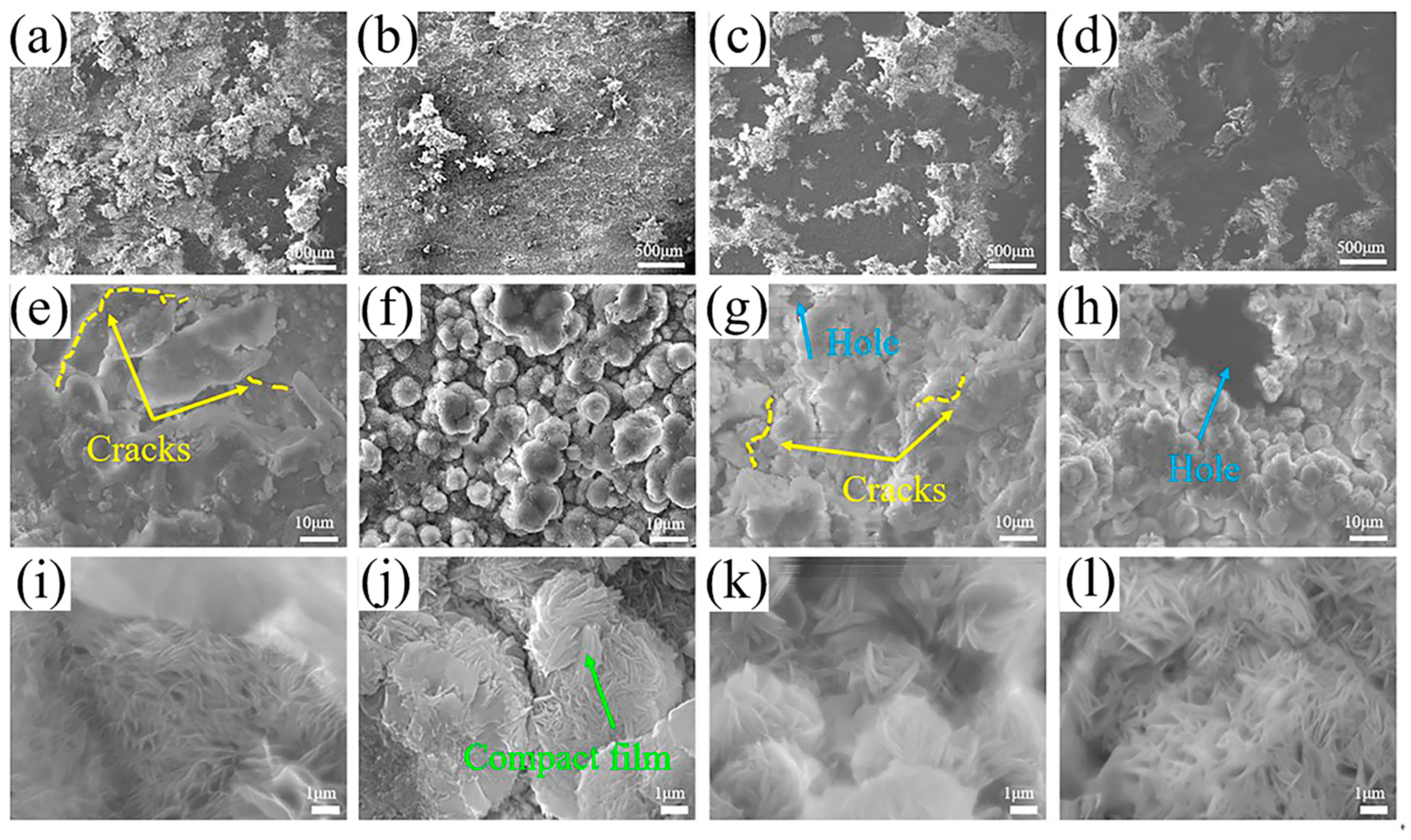
3.3.4. Corrosion Morphologies

The surface morphologies of the samples after immersion for 168 h are shown in Figure 10. From the macroscopic corrosion morphology, it can be observed that the surface of the SiCp/MZY composite remains relatively flat, indicating a uniform corrosion morphology. In contrast, the MZY alloy and SiCnp/MZY composite exhibit some large corrosion pits on surfaces, characterized by severe localized corrosion. The surface of the SiCnw/MZY composite is severely corroded.
At high magnification, the corrosion morphology of alloy reveals a large amount of MgZn2 phase and numerous pits. This indicates that during the corrosion process, the fine high-potential MgZn2 phases act as cathodes, while the surrounding low-potential magnesium matrix corrodes as the anode. As corrosion deepens, the pits grow. These pits are observed in the corrosion morphologies of alloy and composites (Figure 10i–l), which are corroborated by the presence of inductance in the impedance fitting circuit (Figure 10d). Additionally, during the extrusion process, there are non-recrystallized regions in the alloy and composites. According to a report, a large number of dislocations are present in the non-recrystallized regions [46]. These high-dislocation areas and their surroundings form galvanic corrosion pairs that are preferentially corroded. Therefore, the corroded surfaces of four specimens display longitudinal corrosion along the extrusion direction (Figure 10a–d).
The corrosion morphologies of the specimens after immersion for 168 h without removing the products are exhibited in Figure 11. Figure 11e–h reveal that the surface products of SiCnp/MZY and SiCnw/MZY composites have fallen off, and cracks have appeared on the product layer of the MZY alloy. These issues prevent the product film from adequately protecting the matrix. As shown in Figure 11i–l, the corrosion product films of MZY, SiCp/MZY, SiCnp/MZY, and SiCnw/MZY are composed of fibrous clusters. However, the surface films of MZY, SiCnp/MZY, and SiCnw/MZY are porous, with holes in the surface films of SiCnp/MZY and SiCnw/MZY composites. In contrast, the surface film of the SiCp/MZY composite is dense, providing better protection (Figure 11j).
The cross-sections of the MZY alloy and SiCp/MZY composite immersed for 1 day are given in Figure 12. It can be observed that the alloy matrix has deep cracks, indicating that the surface film offers limited protection. In contrast, the surface of the SiCp/MZY composite remains relatively flat, and the matrix is well protected from corrosion. The EDS results suggest that this improved protection may be due to the presence of SiC in the surface film.

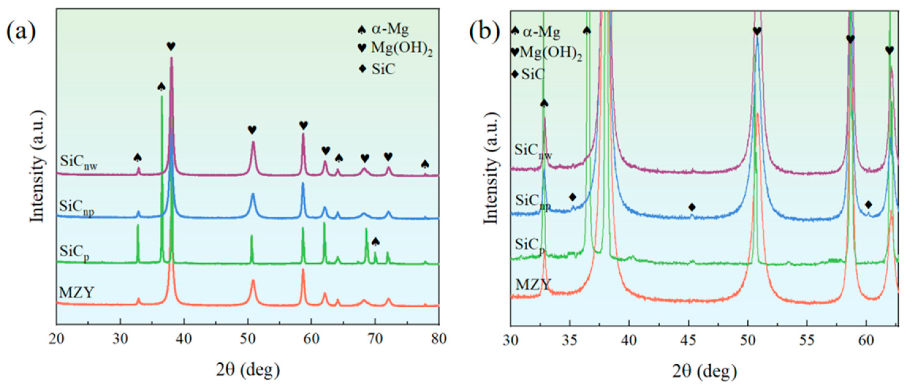
3.3.5. Corrosion Product

To explore the composition of products, samples were immersed for 168 h, and the products were collected. The XRD patterns of products are given in Figure 13. The following reactions occur in the immersion process of magnesium alloy:
Anodic   reaction :   M g M g 2 + + 2 e
Cathodic   reaction :   2 H 2 O + 2 e H 2 + 2 O H
The excess OH in the solution combined with Mg2+ to generate Mg(OH)2, which attached to the metal surface. As seen in Figure 13, the major component of the products was Mg(OH)2. The α-Mg peaks appearing in different samples indicate that α-Mg had fallen off during immersion.

3.3.6. KPFM Measurements

From Figure 14c, it can be observed that the potential difference between the MgZn2 phase and α-Mg in MZY is 0.036 V. In contrast, Figure 14f shows that this potential difference decreases to 0.028 V in the SiCp/MZY composite. The potential difference is a crucial factor causing galvanic corrosion [47,48]. It is noteworthy that SiC exhibits a greater negative potential compared to the second phase. However Lopez et al. [49] investigated the corrosion behavior of SiC in magnesium matrix composites, and found that SiC particles did not undergo microgalvanic corrosion with the Mg matrix. Tiwari et al. [50] confirmed that the potential difference between SiC particles and the Mg matrix had no significant effect on the corrosion rate via mixed potential theory and experimentation. Meanwhile, the content of SiC reinforcements added in this study is only 0.3 wt. %, so the galvanic corrosion between SiC and the Mg matrix is not considered in this paper. In summary, the reduced potential difference between the second phase and the matrix in the SiCp/MZY composite weakens galvanic corrosion. These observations highlight that the inclusion of SiCp reduces the potential difference within the composite, thus enhancing the corrosion resistance.

4. Discussion

4.1. Effect of SiC Morphologies on Mechanical Properties of MZY Alloy

As shown in Figure 5, SiC with different morphologies can promote dynamic recrystallization, resulting in grain refinement and an increased recrystallization rate. This effect is primarily due to the following factors arising during the dynamic recrystallization process: Firstly, SiC reinforcements can act as nucleation sites, leading to the formation of more recrystallized grains. Secondly, the numerous dispersed SiC reinforcements can inhibit grain growth, resulting in finer grains. It is worth noting that the degree of grain refinement varies among different morphologies of SiC, with nano-sized SiC being more effective in grain refinement than submicron SiC particles, and one-dimensional SiCnw being more effective in grain refinement than SiCnp particles. This indicates that the degree of grain refinement is related to the size and morphology of the reinforcements. Greer et al. [51] pointed out that the size of the reinforcements can significantly affect the rate of heterogeneous nucleation and alter the efficiency of grain refinement. In liquid metals, the critical condition for particles to promote heterogeneous nucleation is d > 2r, where d is the diameter of the particles and r is the critical radius for nucleation. Nucleation occurs when the particle sizes satisfy the critical nucleation conditions, a phenomenon known as the free growth model. The relationship between nucleation undercooling ΔTn and the size of reinforcements is described by equation:
Δ T n = 4 σ S L / Δ S ν d p
where σ S L is the solid–liquid interfacial energy, S ν is the melting entropy per unit volume, and d p is the diameter of the reinforcements. From this equation, it can be seen that increasing the size of the reinforcements effectively reduces the nucleation undercooling Δ T n . Since the composites in this paper are selected with the same matrix, σ S L and S ν are considered to be consistent. From Equation (7), it can be seen that the nucleation supercooling degree Δ T n of the composites decreases with the increase in the size of the SiC reinforcements. The smaller the supercooling degree, the faster the grain growth. The grain growth is mainly the result of grain boundary movement. According to Equation (8), it can be seen that the movement rate of the grain boundary is inversely proportional to the grain diameter.
d D d t = K D
where D represents the grain size at time “t”, and K is a constant. There is a critical grain size, D c . The equation for determining the critical grain size D c and particle diameter d is
D c d V
When the grain size exceeds the D c , the particles at the grain boundaries will limit the uniform growth of the grains. Nanoscale SiC ensures a greater inhibition of grain growth due to its small size and small D c . Therefore, compared to submicron SiC, nanoscale SiC has a smaller grain size.
As shown in Figure 14b, it can be observed that the sizes of precipitates in both MZY alloy and SiC/MZY composites show only slight differences, but the number of precipitated phases decreases significantly after adding SiC reinforcements. This is caused by the different morphologies of the SiC reinforcements. According to the thermodynamic and kinetic analyses of precipitates’ nucleation, for the formation of a spherical precipitated phase with a radius r, the free energy change ΔG of the system can be expressed by Equation (10),
Δ G = 4 3 π r 3 Δ G ν + 4 π r 2 γ
where r is the nucleation radius, Δ G ν is the change in volumetric free energy, and γ is the interfacial energy. Δ G exhibits a maximum value Δ G . The size corresponding to the Δ G is called the critical radius r . Let the derivative be 0, that is,
d Δ G d r = d ( 4 3 π r 3 Δ G ν + 4 π r 2 γ ) d r = 0
Therefore, the maximum value of the nucleation free energy Δ G and the critical radius r are given by
Δ G = 16 π r 3 3 Δ G ν 2
r = 2 γ Δ G ν
When SiC is added, the interfacial energy γ increases, leading to an increase in both Δ G and r . This indicates that the free energy required for precipitate nucleation increases, and the critical size for nucleation also becomes larger, making nucleation more difficult. According to nucleation kinetics, the nucleation rate (I) is expressed by Equation (14),
I = N ν e x p Δ G k T
where N is the number of available nucleation sites, ν is the atomic vibration frequency, k is the Boltzmann constant, and T is the absolute temperature. When ΔG increases, the nucleation rate I will significantly decrease. Therefore, according to Equations (12)–(14), the addition of SiC reinforcements results in an increase in the free energy and a decrease in the rate of nucleation, leading to a significant decrease in the amount of precipitates compared to the alloy. According to the nucleation thermodynamics of the precipitates, it is known that a reduction in Gibbs free energy of the matrix can promote the nucleation of precipitates [52]. Therefore, nucleation often occurs in regions where interface and strain energy can be reduced, such as dislocations and grain boundaries. From the above, it can be seen that SiCnw/MZY has significantly smaller grains with more grain boundaries. Therefore, the volume fraction of precipitates in SiCnw/MZY composites is relatively high compared to SiCp/MZY and SiCnp/MZY. The precipitated phase consists of two phases, nucleation and growth, with the growth phase being dominated by diffusion. The growth rate at the interface (spherical or circular) of the precipitated phase is given by Equations (15)–(17).
ν = d R d t = K R Δ G m
Δ G m = Δ G m Δ G T
Δ G T = 2 γ V m R
where K is the kinetic parameter, ΔGm is the phase transition driving force, ΔGT is the Gibbs–Thompson energy difference, and R is the nucleation radius. From the above, compared to submicron SiC particles, it is clear that nanoscale SiC has a larger interfacial energy and a larger nucleation radius, resulting in a smaller growth rate of the precipitated phase. Meanwhile, the presence of SiC reinforcements also limits the growth of the precipitated phase. For SiCp/MZY, the relatively small number of reinforcements weakens the growth-limiting effect. In contrast, the more numerous nano-sized SiCnp particles more effectively limit the growth of precipitates, resulting in variations in the sizes of precipitates.
From the above, the grain size is significantly refined with the addition of SiC, which enhances the strength through fine grain strengthening. Additionally, after extrusion, the non-recrystallization regions contain numerous dislocations, which cannot easily deform the regions, contributing to increased yield strength. However, the mechanisms of strength improvement vary with different morphologies of SiC. For SiCp/MZY, the relatively small number of reinforcements results in a lower degree of recrystallization and fewer second phases.
As shown in Figure 5, excellent mechanical properties (YS exceeding 440 MPa) were obtained for the composites by adding SiC reinforcements. The increase in YS is mainly due to the dynamic recrystallisation that occurs during the extrusion process and the dislocations contained in the deformation zone. However, the mechanisms of strength improvement vary with different morphologies of SiC. In the case of SiCp/MZY, the larger size of the reinforcements prevents the suppression of a dislocation motion. The lower degree of dynamic recrystallization results in a high number of dislocations compared to nanocomposites. Therefore, the increase in yield strength of SiCp/MZY mainly comes from the dislocation reinforcement caused by dislocations in the deformation zone. Therefore, the impact of submicron SiCp on yield strength primarily stems from the dislocation strengthening caused by the numerous dislocations in the non-recrystallization regions. The process of the strengthening of YS by dislocations is given in Equation (18),
σ d = f u n D R X e d M α G b ρ
where σ d is the YS of the unDRXed region, f u n D R X e d is the volume fraction of unDRXed region, M is the Taylor factor, α is 0.2, G is the Shear modulus, b is the Burger vector, and ρ is the density of dislocations in the unDRXed region.
For SiCnp/MZY, the small size of the nanoparticles leads to a pinning effect on dislocations, meaning the Orowan strengthening plays a significant role. Further, due to the high degree of recrystallisation, the enhancement in YS depends to a large extent on the Orowan strengthening. The equations for the increase in YS caused by Orowan strengthening are as follows:
σ O r a w a n = M · Δ τ O r a w a n
Δ τ O r a w a n = G b 2 π 1 ν 0.779 f v p 0.785 d p l n 0.785 d p b
where Δ τ O r a w a n is the shear stress, ν is the Poisson’s ratio of magnesium alloy (0.35), f v p is the volume fraction of precipitates and d p is the average size of precipitates.
For SiCnw/MZY, during the tensile testing, due to the significant strength difference between the matrix and the reinforcements and the good interfacial bonding, the external load is easily transferred from the matrix to the reinforcements with higher strength through the matrix–reinforcement interface. The load transfer is related to the length and cross-sectional area of the reinforcements, as well as the interfacial bond between the reinforcements and the matrix. For SiC particles, there is almost no load transfer strengthening. Since one-dimensional SiCnw has a large aspect ratio and can bear greater loads along the axial direction, the load transfer strengthening is particularly prominent in one-dimensional SiCnw. The increase in YS resulting from load transfer strengthening is described by the following equation:
σ L = σ m f ν l 2 d 1
where σ m is the YS of the matrix, f ν is the volume fraction of reinforcements, and l and d are the dimensions of the reinforcements parallel and perpendicular to the external load, respectively. The SiCnw reinforcements are distributed axially in parallel to the extrusion direction after extrusion, and the parallel and perpendicular load dimensions are the length and diameter of the reinforcements. Additionally, for SiCnw/MZY composites, the grain size is the smallest, resulting in the most significant increase in YS due to fine grain strengthening. The equation for fine grain strengthening is as follows:
Δ σ H a l l   P e t c h = f D R X e d · k m · d c o m 1 / 2
where Δ σ H a l l   P e t c h is the YS of the recrystallization region (MPa), f D R X e d is the volume fraction of the DRXed region, d c o m is the recrystallized grain size, and k m represents the Hall–Petch constant.
In summary, among the three composites, SiCnw/MZY benefits from a unique morphology that allows the fine grain strengthening to work in conjunction with the load transfer strengthening, and thus exhibits the highest strength. For SiCp/MZY and SiCnp/MZY, most of the increase in YS is dependent on fine grain strengthening. In addition to this, the YS of SiCnp/MZY benefits from Orowan strengthening due to the inhibition of the dislocation motion by small size particles, while SiCp/MZY benefits from the presence of a large number of dislocations in the deformation regions, which leads to an increase in YS.

4.2. Effect of SiC Morphologies on Corrosion Properties of MZY Alloy

As stated in Section 3.3, only the SiCp led to simultaneous improvements in mechanical and corrosion properties. The corrosion mechanism is illustrated in Figure 15. For SiCp/MZY, due to the reduced number of second phase regions and fewer unrecrystallized regions (in Figure 5), the number of galvanic coupling pairs within the composite is significantly reduced. Therefore, compared with the MZY alloy, in the initial stage of corrosion, there are fewer regions of preferential corrosion in SiCp/MZY. At the same time, since the potential difference between the MgZn2 and α-Mg in SiCp/MZY is smaller than that in the MZY alloy (in Figure 14), the corrosion driving force of the Mg matrix in SiCp/MZY is lower. The corrosion expansion is much slower for the same immersion time. Consequently, the corrosion rate of SiCp/MZY is significantly reduced compared to the alloy.
For SiCnw/MZY, a large number of non-recrystallization regions with numerous dislocations undergo galvanic corrosion with the surrounding matrix. Additionally, the nanometer-sized MgZn2 precipitates at the grain boundaries act as cathodes, accelerating the corrosion. Meanwhile, due to the small size and large number of SiCnw reinforcements, there are many interfaces between the reinforcements and the matrix. These interfaces contain numerous dislocations, which promote the corrosion. Therefore, the corrosion rate of SiCnw/MZY is greatly increased.
For SiCp/MZY and SiCnp/MZY, the sizes and numbers of precipitates are similar. However, the grain size of SiCnp/MZY is finer than that of SiCp/MZY. A linear negative correlation between corrosion rate and grain size has been reported for magnesium alloys with uniform organization. This is due to the reduction in high-energy regions such as grain boundaries [53]. In this paper, hot extrusion improved the uniformity of the microstructure, so SiCnp/MZY with finer grains exhibits a higher corrosion rate due to the presence of more grain boundaries. At the same time, the second phase is dispersed along the grain boundaries, and the matrix around the second phase undergoes galvanic corrosion, making the grain boundaries unable to act as a barrier to inhibit corrosion extension. Additionally, there are more interfaces between the SiCnp and the matrix compared to SiCp, leading to more corrosion-prone areas caused by the interfaces. As a result, the corrosion rate of SiCnp/MZY is relatively high due to the presence of more reinforcements and fine grains.
It is noteworthy that the surface film becomes denser with the addition of submicron SiCp (in Figure 11j). This improvement is attributed to the existence of SiC on the surface (in Figure 12). As seen in Table 3, the Rct values of the SiCp/MZY and SiCnp/MZY composites are higher than those of the alloy, indicating that charge transfer within the surface film of these composites is more difficult. This suggests that the addition of SiC particles can prevent corrosive ions from penetrating the Mg matrix. Equation (17) reflects the relationship between the thickness of the surface passivation film and the effective capacitance [54],
d = ε 0 × ε r / C
where d is the thickness of the passivation film, ε0 is the dielectric constant of air, εr is the dielectric constant of the passivation film, and C is the capacitance of the passivation film. Since all the products of alloy and composites are Mg (OH)2 (in Figure 12), the dielectric constant of the surface film is considered to be constant. From Table 3, it is evident that the passive film capacitance (CPE2) of the SiCp/MZY composite is smaller than that of the MZY alloy. According to Equation (11), it can be concluded that the surface film of the SiCp/MZY composite is thicker. A thicker passivation film indicates a better protective performance [55].
The process of surface film formation during corrosion for MZY alloy and SiCp/MZY composite is illustrated in Figure 16. For the MZY alloy, after a period of corrosion, a protective Mg (OH)2 film can eventually form on the alloy surface. However, by this time, extensive galvanic corrosion within the alloy will have already caused surface pits and metal loss. In contrast, for SiCp/MZY, the SiC particles on the composite surface provide nucleation sites for Mg (OH)2, accelerating the formation of the protective film. The lighter internal corrosion in the composite helps maintain a smooth surface. As the corrosion time increases, the Mg (OH)2 film on the surface gradually thickens, preventing corrosive ions from penetrating into the matrix and further protecting the matrix from corrosion.
However, from Table 3, it is evident that the surface film resistance, Rf, of the alloy is still higher than that of the SiCnp/MZY and SiCnw/MY composites. This may be due to the fact that the surface films on them are more prone to cracking (Figure 10g,h). With prolonged corrosion, the interface corrosion between reinforcements and α-Mg, as well as corrosion in the unrecrystallized regions, progresses both longitudinally and transversely. This exerts multidirectional pressure on the produced film, leading to cracks and significant metal loss. For the nano-SiC composites, the numerous interfaces with the matrix and the increased number of galvanic coupling pairs result in a surface film that is more prone to cracking and detachment, forming holes and thus lowering the Rf value compared to the alloy. In contrast, the SiCp/MZY composite, with fewer galvanic coupling pairs and interfaces, experiences less corrosion over the same immersion period. This results in less pressure on the surface film, allowing it to maintain better integrity. Therefore, the addition of submicron particle reinforcements provides better corrosion resistance than nano-sized reinforcements.

5. Conclusions

In this paper, the mechanical and corrosion properties of MZY alloy and SiC composites (SiCp/MZY, SiCnp/MZY and SiCnw/MZY) after extrusion were investigated. The influences of different SiC morphologies on the microstructure and properties of MZY were studied. The main conclusions are as follows:
(1)
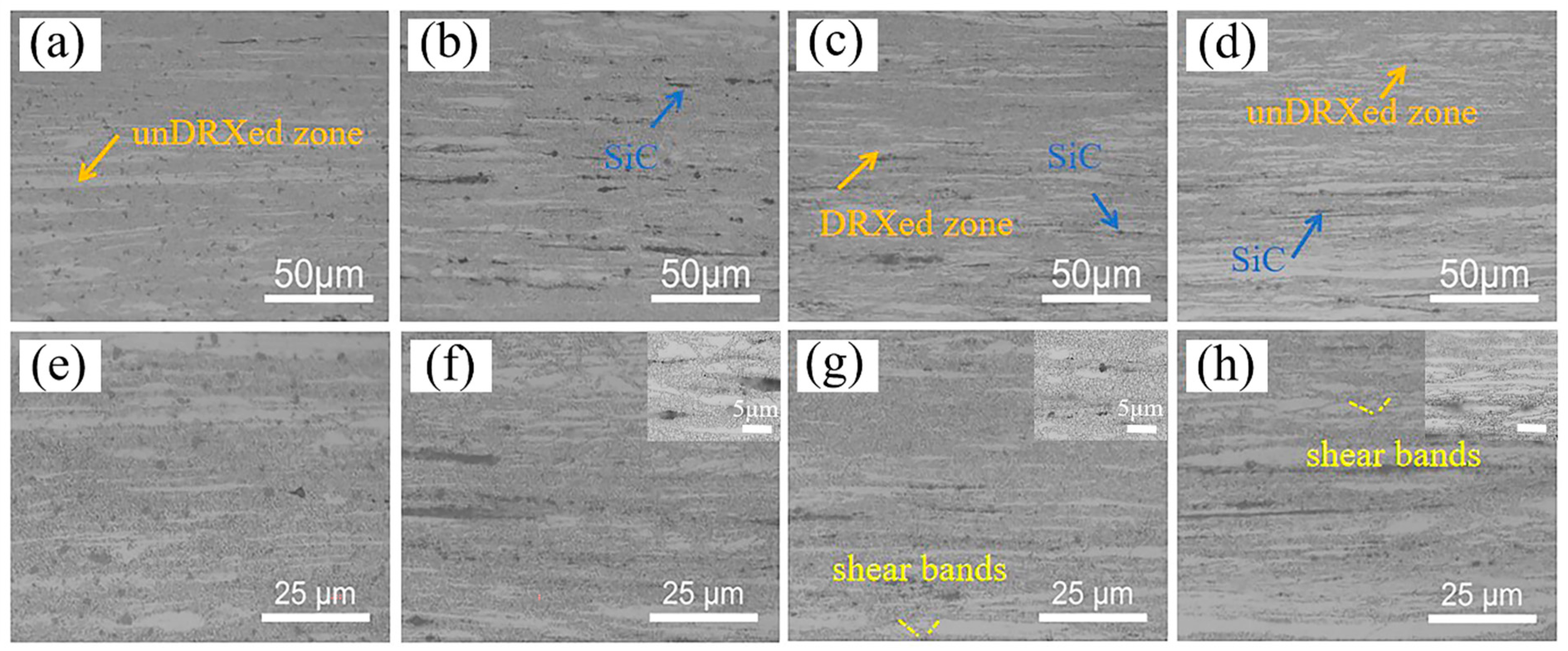
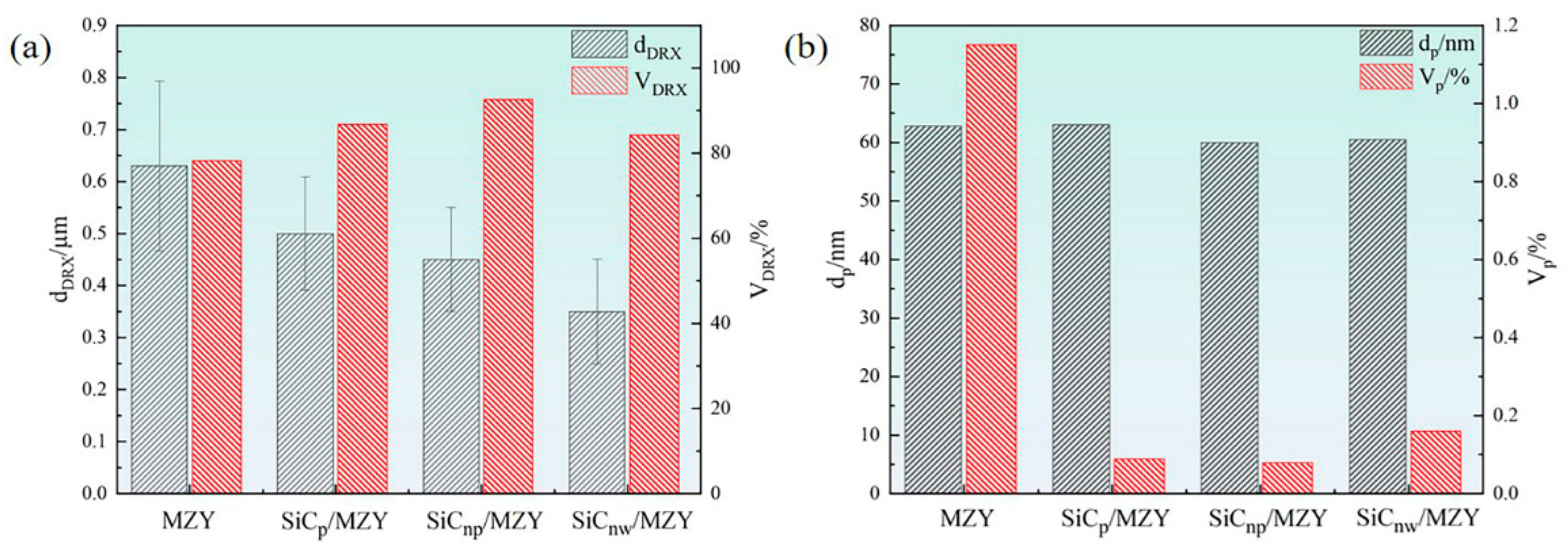
After extrusion, visible dynamic crystallization occurred in the alloy and composites, and the recrystallization degree of SiCnp/MZY was the highest, reaching 92.6%. The addition of SiC reduced the grain size and decreased the number of second phases significantly. The SiCnw/MZY composite had the finest grains and the SiCnp/MZY composite had the lowest number of second phases;
(2)
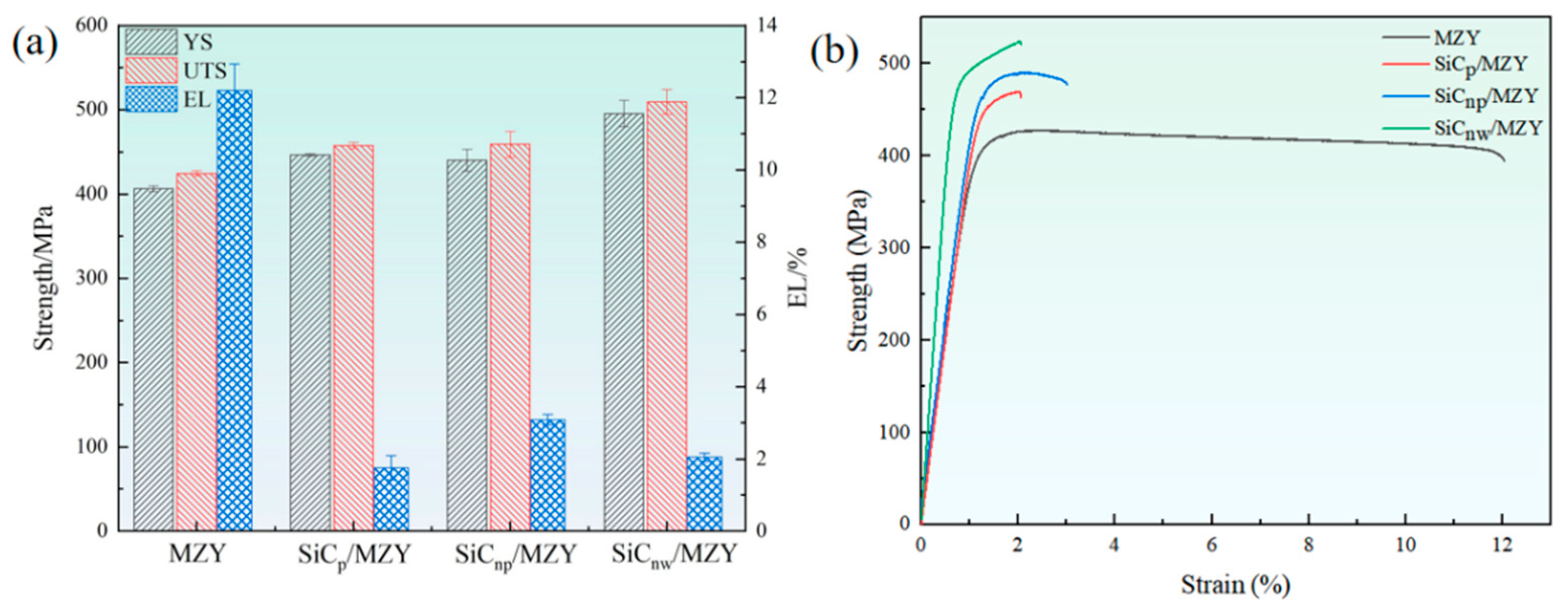
Compared with MZY, the strength of SiC/MZY was improved, with a YS of more than 440 MPa and an ultimate tensile strength of more than 450 MPa. SiCnw/MZY had the highest strengths, with YS and UTS values of ~495.5 MPa and ~509.4 MPa, respectively. For different composites, the SiC reinforcements promoted fine grain strengthening. However, SiCnw could improve the strength through load transfer due to its large aspect ratio. A large number of small SiCnp had a pinning effect on the dislocations, and improved the strength of the composites through Orowan strengthening. On the other hand, submicron SiCp with a larger size improved the strength through dislocations;
(3)
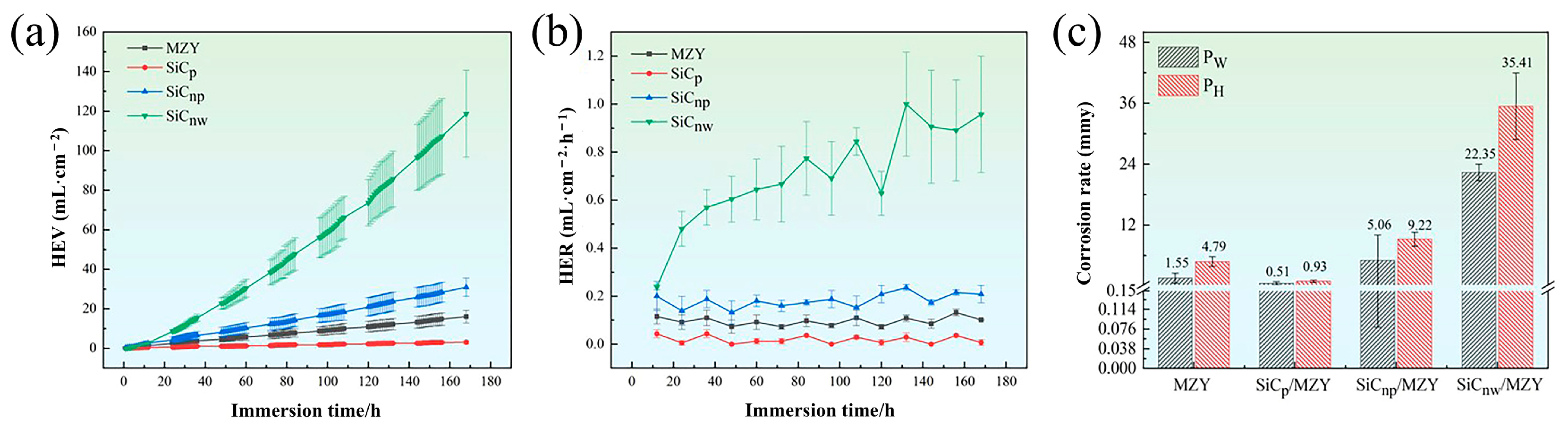
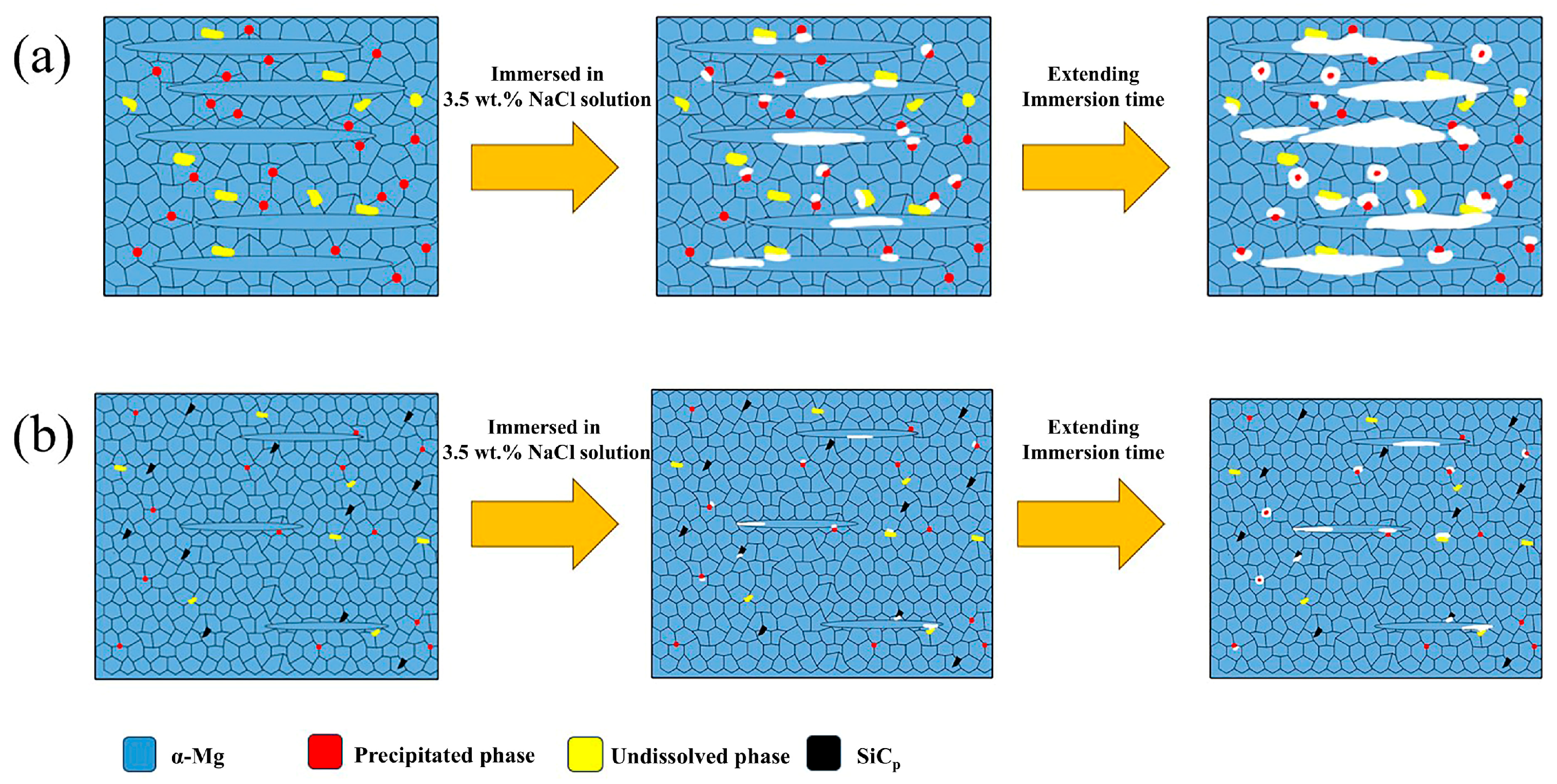
Compared with alloy, SiCp/MZY was benefited by the presence of few galvanic coupling pairs and reduced potential difference, resulting in a hydrogen evolution corrosion rate (PH) that was 81% lower than that of MZY alloy (PH 0.93 mm/y, PW 0.51 mm/y). On the other hand, SiCnp/MZY increased the corrosion rate due to the large number of reinforcements-to-matrix interfaces and high energy grain boundaries (PH 9.22 mm/y, PW 5.06 mm/y). The increase in second phase and the decrease in the recrystallization rate in SiCnw/MZY resulted in a faster corrosion rate (PH 35.41 mm/y, PW 22.35 mm/y) compared to SiCnp/MZY;
(4)
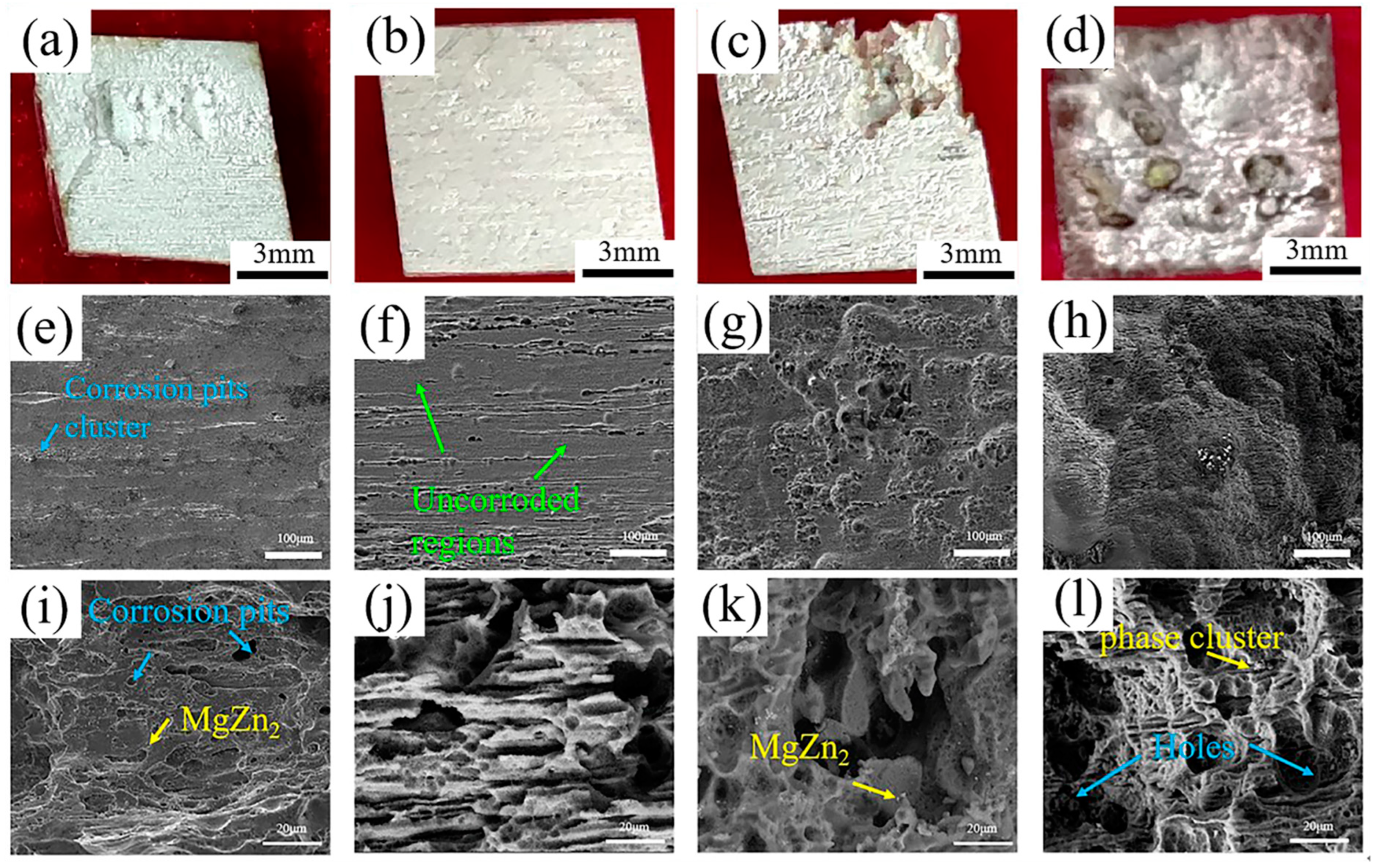
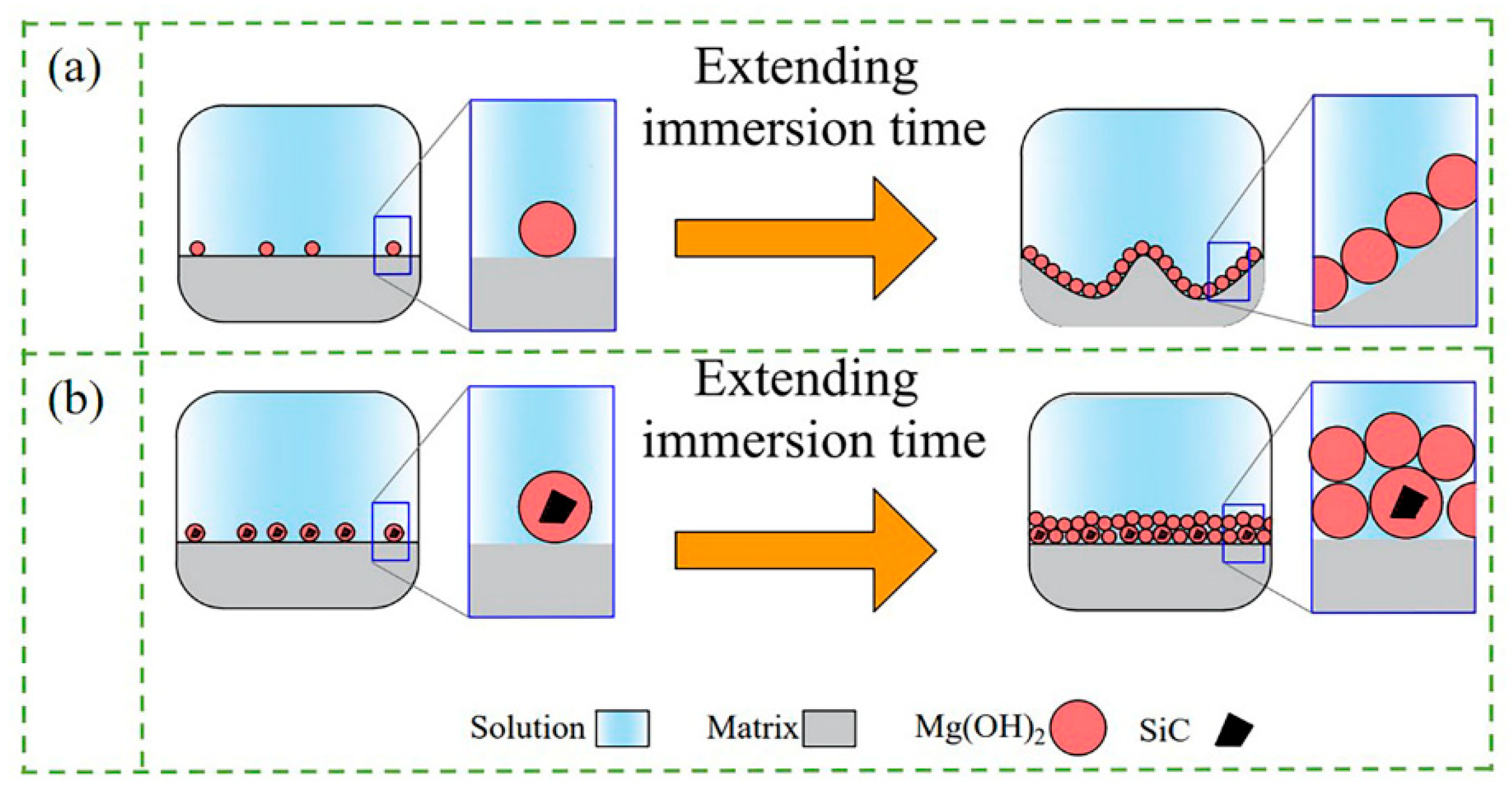
The presence of SiC particles on the composite surface prevented corrosive ions from entering the matrix, and provided nucleation sites for Mg(OH)2 to form a thicker protective film more rapidly. However, the protective films on the surfaces of SiCnp/MZY and SiCnw/MZY were more prone to cracking and further expansion with the extension of the corrosion time. The larger size of submicron SiCp could not only improve the formation of protective film, but also reduce the internal galvanic corrosion, which further ensured the integrity and protection of the surface film;
(5)
The high-strength and corrosion-resistant materials prepared by the semi-solid stirring method in this study exhibited excellent performance and relatively low cost. The combination of high strength, corrosion resistance, and cost-effectiveness makes these materials highly valuable for a wide range of marine and offshore engineering applications. This study provides valuable insights and design ideas for future material development and applications in these fields.

Author Contributions

F.G.: writing—review and editing, writing—original draft, methodology, investigation, data curation. K.N.: supervision, project administration, methodology, funding acquisition, conceptualization. K.D.: supervision, project administration. Y.L.: investigation, conceptualization. All authors have read and agreed to the published version of the manuscript.

Funding

This work was supported by the Fundamental Research Program of Shanxi Province (Grant numbers 202203021221088 and 202403021211064); the Fund Program for the Scientific Activities of Selected Returned Overseas Professionals in Shanxi Province (Grant No. 20230010); the Shanxi Provincial Science and Technology Major Special Project plan of “Taking the lead in unveiling the list” (Grant No. 202201050201012); the Research Project Supported by Shanxi Scholarship Council of China (Grant No. 2023-063); the National Natural Science Foundation of China (Grant numbers 52271109 and 52401162).

Data Availability Statement

The original contributions presented in this study are included in the article. Further inquiries can be directed to the corresponding author.

Conflicts of Interest

The authors declare that they have no known competing financial interests or personal relationships that could have appeared to influence the work reported in this paper.

References

  1. Kim, S.-H.; Lee, S.W.; Moon, B.G.; Kim, H.S.; Park, S.H. Variation in dynamic deformation behavior and resultant yield asymmetry of AZ80 alloy with extrusion temperature. J. Mater. Sci. Technol. 2020, 46, 225–236. [Google Scholar] [CrossRef]
  2. Guo, R.; Le, Q.; Zhou, W.; Wang, T.; Ren, L.; Jiang, Y.; Zou, Q.; Liao, Q.; Yu, F.; Aranas, C., Jr. Effect of SiCp on the microstructure and tensile properties of the Mg–3Y magnesium alloy. J. Mater. Res. Technol. 2023, 24, 4232–4241. [Google Scholar] [CrossRef]
  3. Lee, J.U.; Kim, S.-H.; Lee, D.H.; Kim, H.J.; Kim, Y.M.; Park, S.H. Variations in microstructure and bending formability of extruded Mg–Al–Zn–Ca–Y–MM alloy with precompression and subsequent annealing treatment conditions. J. Magnes. Alloys 2021, 10, 2475–2490. [Google Scholar] [CrossRef]
  4. Park, S.H.; Kim, S.-H.; Kim, Y.M.; You, B.S. Improving mechanical properties of extruded Mg–Al alloy with a bimodal grain structure through alloying addition. J. Alloys Compd. 2015, 646, 932–936. [Google Scholar] [CrossRef]
  5. Kim, S.-H.; Lee, J.U.; Kim, Y.J.; Jung, J.-G.; Park, S.H. Controlling the microstructure and improving the tensile properties of extruded Mg-Sn-Zn alloy through Al addition. J. Alloys Compd. 2018, 751, 1–11. [Google Scholar] [CrossRef]
  6. Kim, S.-H.; Park, S.H. Underlying mechanisms of drastic reduction in yield asymmetry of extruded Mg-Sn-Zn alloy by Al addition. Mater. Sci. Eng. A 2018, 733, 285–290. [Google Scholar] [CrossRef]
  7. Yang, J.; Heogh, W.; Ju, H.; Kang, S.; Jang, T.-S.; Jung, H.-D.; Jahazi, M.; Han, S.C.; Park, S.J.; Kim, H.S.; et al. Functionally graded structure of a nitride-strengthened Mg2Si-based hybrid composite. J. Magnes. Alloys 2024, 12, 1239–1256. [Google Scholar] [CrossRef]
  8. Xu, H.; Zhang, X.; Zhang, K.; Shi, Y.; Ren, J. Effect of extrusion on corrosion behavior and corrosion mechanism of Mg-Y alloy. J. Rare Earths 2016, 34, 315–327. [Google Scholar] [CrossRef]
  9. Luo, Y.; Deng, Y.; Guan, L.; Ye, L.; Guo, X.; Luo, A. Effect of grain size and crystal orientation on the corrosion behavior of as-extruded Mg-6Gd-2Y-0.2Zr alloy. Corros. Sci. 2020, 164, 108338. [Google Scholar] [CrossRef]
  10. Zhang, K.; Wang, C.; Wang, D.-W.; Li, M.-X.; Ma, Y.-L.; Hua, Z.-M.; Zhang, L.-Y.; Li, J.; Wang, H.-Y. Effects of solute redistribution during heat treatment on micro-galvanic corrosion behavior of dilute Mg-Al-Ca-Mn alloy. Corros. Sci. 2023, 213, 110971–110987. [Google Scholar] [CrossRef]
  11. Atrens, A.; Chen, X.; Shi, Z. Mg Corrosion-Recent Progress. Corros. Mater. Degrad. 2022, 3, 566–597. [Google Scholar] [CrossRef]
  12. AbdelGawad, M.; Usman, C.A.; Shunmugasamy, V.C.; Karaman, I.; Mansoor, B. Corrosion behavior of Mg-Zn-Zr-RE alloys under physiological environment-Impact on mechanical integrity and biocompatibility. J. Magnes. Alloy. 2022, 10, 1542–1572. [Google Scholar] [CrossRef]
  13. Song, J.; Chen, J.; Xiong, X.; Peng, X.; Chen, D.; Pan, F. Research advances of magnesium and magnesium alloys worldwide in 2021. J. Magnes. Alloy. 2022, 10, 863–898. [Google Scholar] [CrossRef]
  14. Atrens, A.; Shi, Z.; Mehreen, S.U.; Johnston, S.; Song, G.-L.; Chen, X.; Pan, F. Review of Mg alloy corrosion rates. J. Magnes. Alloys 2020, 8, 989–998. [Google Scholar] [CrossRef]
  15. Yang, Y.; Xiong, X.; Chen, J.; Peng, X.; Chen, D.; Pan, F. Research advances in magnesium and magnesium alloys worldwide in 2020. J. Magnes. Alloys 2021, 9, 705–747. [Google Scholar] [CrossRef]
  16. Prasad, S.V.S.; Verma, K.; Mishra, R.K.; Kumar, V.; Singh, S. The role and significance of Magnesium in modern day research-A review. J. Magnes. Alloys 2022, 10, 1–61. [Google Scholar] [CrossRef]
  17. Jin, Y.; Tian, L.; Huang, Z.; Wang, F. Improving the electrochemical corrosion resistance of a high-Ca heat-resistant magnesium alloy by enhancing the barrier effect of the cathodic phase skeleton. J. Alloys Compd. 2025, 1010, 177728. [Google Scholar] [CrossRef]
  18. Yu, F.; Peng, Y.; Liu, F.; Peng, P.; Zhang, C.; Long, S.; Zhang, J.; Yang, Q.; Dai, Q.; She, J.; et al. Synergistic optimization of mechanical properties and corrosion resistance in Sm-doped Mg-Gd-Zn-Zr biodegradable magnesium alloys. J. Rare Earths 2024. [Google Scholar] [CrossRef]
  19. Lin, Y.; Zhang, X.; Le, Q.; Wang, T.; Liao, Q.; Liu, L. Achieving the improvement of tensile properties and corrosion resistance of Mg-Gd-Sn-Y-Zn-Mn alloy by increasing the concentration of solute elements in nearly equal-amplitude. J. Alloys Compd. 2025, 1010, 178323. [Google Scholar] [CrossRef]
  20. Wan, D.Q.; Sun, Y.M.; Xue, Y.D.; Dong, S.Y.; Han, G.L.; Wang, Y.; Yang, F.; Tang, H.; Wang, Y.Y. Improvement in corrosion resistance of Mg97Zn1Y2 alloy by Zr addition. China Foundry 2024, 21, 634–640. [Google Scholar] [CrossRef]
  21. Patil, A.; Nartu, M.S.K.K.Y.; Ozdemir, F.; Banerjee, R.; Gupta, R.K.; Borkar, T. Enhancement of the mechanical properties of graphene nanoplatelet (GNP) reinforced nickel matrix nanocomposites. Mater. Sci. Eng. A 2021, 817, 141324. [Google Scholar] [CrossRef]
  22. Guo, Y.; Nie, K.; Deng, K.; Liu, Z.; Shi, Q. Strength-plasticity-matched (GNPs+GFs)/Mg–3Zn-0.1Ymagnesium matrix composites with high modulus through liquid-phase dispersion and multistep deformation. Compos. Commun. 2024, 45, 101774. [Google Scholar] [CrossRef]
  23. Xiao, L.; Liu, T.-T.; Chu, Y.; Song, B.; Zhao, J.; Chen, X.-H.; Zheng, K.-H.; Pan, F.-S. Effect of Ti Particles on the Microstructure and Mechanical Properties of AZ91 Magnesium Matrix Composites. Acta Metall. Sin. (Engl. Lett.) 2024, 37, 513–524. [Google Scholar] [CrossRef]
  24. Zhao, Y.; Wu, Z.; Guo, S.; Zhou, Z.; Miao, Z.; Xie, S.; Huang, R.; Li, L. Hyperbranched graphene oxide structure-based epoxy nanocomposite with simultaneous enhanced mechanical properties, thermal conductivity, and superior electrical insulation. Compos. Sci. Technol. 2022, 217, 109082. [Google Scholar] [CrossRef]
  25. He, H.; Fan, G.; Saba, F.; Tan, Z.; Su, Z.; Xiong, D.; Li, Z. Enhanced distribution and mechanical properties of high content nanoparticles reinforced metal matrix composite prepared by flake dispersion. Compos. Part B 2023, 252, 110514. [Google Scholar] [CrossRef]
  26. Sager, A.; Esen, I.; Ahlatçi, H.; Turen, Y. Characterization and corrosion behavior of composites reinforced with ZK60, AlN, and SiC particles. Eng. Sci. Technol. 2023, 41, 101389. [Google Scholar] [CrossRef]
  27. Yang, L.; Shi, X.-H.; Feng, G.-H.; Tian, X.-F.; Wang, J.-C.; Qi, L.-H. Effect of SiC doping on corrosion behavior of Cf/Mg composites. Ceram. Int. 2020, 46, 22564–22574. [Google Scholar] [CrossRef]
  28. Singla, S.; Kang, A.S.; Sidhu, T. Characterization and electrochemical corrosion behaviour of FSPed WE43/nano-SiC surface composite. Mater. Today Proc. 2020, 26, 3138–3144. [Google Scholar] [CrossRef]
  29. Zakaria, H.M. Microstructural and corrosion behavior of Al/SiC metal matrix composites. Ain Shams Eng. J. 2014, 5, 831–838. [Google Scholar] [CrossRef]
  30. Esmaily, M.; Mortazavi, N.; Svensson, J.; Halvarsson, M.; Jarfors, A.; Wessén, M.; Arrabal, R.; Johansson, L. On the microstructure and corrosion behavior of AZ91/SiC composites produced by rheocasting. Mater. Chem. Phys. 2016, 180, 29–37. [Google Scholar] [CrossRef]
  31. Velavan, K.; Palanikumar, K.; Dhanush, V.; Rajapandiyan, S.; Kumar, U.T.; Aishwarya, M. Corrosion and microstructure studies on magnesium alloy composite reinforced with mSiCp fabricated via powder metallurgy. Mater. Today Proc. 2023, 72, 2132–2138. [Google Scholar] [CrossRef]
  32. Zhou, Q.; Dai, X.; Zhang, X.; Liu, X.; Rao, J.; Zhang, Y.; Hou, Y. Core-shell Co-doped NiFe LDH@SiCnw nanocomposite towards efficiency microwave absorption with corrosion resistance. Appl. Surf. Sci. 2024, 655, 159633. [Google Scholar] [CrossRef]
  33. Lv, X.; Deng, K.; Wang, C.; Nie, K.; Shi, Q.; Niu, H. The corrosion resistance and discharge performance of as-extruded AZ91 alloy synergistically improved by the addition of submicron SiCp. Electrochim. Acta 2023, 441, 141843. [Google Scholar] [CrossRef]
  34. Sun, Y.; Wang, R.; Peng, C.; Cai, Z. Microstructure and corrosion behavior of as-extruded Mg-xLi-3Al-2Zn-0.2Zr alloys (x = 5, 8, 11 wt.%). Corros. Sci. 2020, 167, 108487. [Google Scholar] [CrossRef]
  35. Chen, Y.H.; Gao, X.Y.; Nie, K.B.; Li, Y.N.; Deng, K.K. Different effects of SiC dimensions on the microstructure and mechanical properties of magnesium matrix composites. Mater. Sci. Eng. A 2022, 847, 108487. [Google Scholar] [CrossRef]
  36. Vignesh, P.; Ramanathan, S.; Ashokkumar, M.; Sonar, T.; Ananthi, V. Microstructure, Mechanical, and Electrochemical Corrosion Performance of Ti/HA (Hydroxyapatite) Particles Reinforced Mg-3Zn Squeeze Casted Composites. Int. J. Met. 2023, 18, 1348–1360. [Google Scholar] [CrossRef]
  37. Luo, Y.; Huang, J.; Yu, X.; Xie, Y.; Zhang, J.; Yu, S.; Fan, D.; Liu, J. Surface microstructure and corrosion characterization of AZ31 magnesium alloys fabricated by laser surface-modification. J. Alloys Compd. 2024, 994, 174708. [Google Scholar] [CrossRef]
  38. Yin, S.; Duan, W.; Liu, W.; Wu, L.; Yu, J.; Zhao, Z.; Liu, M.; Wang, P.; Cui, J.; Zhang, Z. Influence of specific second phases on corrosion behaviors of Mg-Zn-Gd-Zr alloys. Corros. Sci. 2020, 166, 108419. [Google Scholar] [CrossRef]
  39. Gu, J.; Hu, Z.; Zhu, H.; Lu, D. Effect of laser cavitation peening on surface integrity and electrochemical corrosion behavior of magnesium alloy. Mater. Today Commun. 2024, 38, 107806. [Google Scholar] [CrossRef]
  40. Ren, Y.; Wan, T.; Xu, Y.; Zhang, K.; Zhang, M.; Li, J. Effects of stress aging treatment on the microstructure, mechanical properties and electrochemical corrosion behavior of Al-Zn-Mg-Cu alloy. J. Alloys Compd. 2024, 997, 174686. [Google Scholar] [CrossRef]
  41. Zhu, Y.-X.; Song, G.-L.; Wu, P.-P.; Zheng, D.-J.; Wang, Z.-M. A burnished and Al-alloyed magnesium surface with improved mechanical and corrosion properties. Corros. Sci. 2021, 184, 109395. [Google Scholar] [CrossRef]
  42. Zhang, C.; Wu, L.; Liu, H.; Huang, G.; Jiang, B.; Atrens, A.; Pan, F. Microstructure and corrosion behavior of Mg-Sc binary alloys in 3.5 wt.% NaCl solution. Corros. Sci. 2020, 174, 108831. [Google Scholar] [CrossRef]
  43. Feng, Y.-J.; Wei, L.; Chen, X.-B.; Li, M.-C.; Cheng, Y.-F.; Li, Q. Unexpected cathodic role of Mg41Sm5 phase in mitigating localized corrosion of extruded Mg-Sm-Zn-Zr alloy in NaCl solution. Corros. Sci. 2019, 159, 108133. [Google Scholar] [CrossRef]
  44. Wu, L.P. Potentiostatic preparation and in vitro characterization of functional hazenite conversion coatings on AZ31 magnesium alloy. Surf. Coat. Technol. 2024, 476, 130215. [Google Scholar] [CrossRef]
  45. Bahmani, A.; Shin, K.S. Controlling the microstructure and texture using multidirectional forging to develop a low corrosion rate Mg alloy. Corrosion 2020, 76, 750–765. [Google Scholar] [CrossRef]
  46. Li, W.; Nie, K.; Liu, Z.; Deng, K.; Li, Y.; Tong, X. Effect of hot extrusion on the microstructure and mechanical properties of SiCNWs/Mg-2Zn-0.1Y composite. Mater. Charact. 2022, 189, 111970. [Google Scholar] [CrossRef]
  47. Le, T.; Mao, P.; Hu, W.; Le, Q. The electrochemical corrosion behaviors and Mg-air battery anode performance of Mg–1Sn–1Ca-0.3Mn alloy with different grain size and Mg2Ca morphology. J. Power Sources 2024, 608, 234297. [Google Scholar] [CrossRef]
  48. Rahmati, M.; Zahrani, E.M.; Atapour, M.; Nezhad, A.N.; Hakimizad, A.; Alfantazi, A. In situ synthesis and electrochemical corrosion behavior of plasma electrolytic oxidation coating containing an osteoporosis drug on AZ31 magnesium alloy. Mater. Chem. Phys. 2024, 315, 128983. [Google Scholar] [CrossRef]
  49. Nunez-Lopez, C.; Habazaki, H.; Skeldon, P.; Thompson, G.; Karimzadeh, H.; Lyon, P.; Wilks, T. An investigation of microgalvanic corrosion using a model magnesium–silicon carbide metal matrix composite. Corros. Sci. 1996, 38, 1721–1729. [Google Scholar] [CrossRef]
  50. Tiwari, S.; Balasubramaniam, R.; Gupta, M. Corrosion behavior of SiC reinforced magnesium composites. Corros. Sci. 2007, 49, 711–725. [Google Scholar] [CrossRef]
  51. Greer, A.; Bunn, A.; Tronche, A.; Evans, P.; Bristow, D. Modelling of inoculation of metallic melts: Application to grain refinement of aluminium by Al–Ti–B. Acta Mater. 2000, 48, 2823–2835. [Google Scholar] [CrossRef]
  52. Li, W.-J.; Deng, K.-K.; Zhang, X.; Wang, C.-J.; Kang, J.-W.; Nie, K.-B.; Liang, W. Microstructures, tensile properties and work hardening behavior of SiCp/Mg-Zn-Ca composites. J. Alloys Compd. 2017, 695, 2215–2223. [Google Scholar] [CrossRef]
  53. Savaedi, Z.; Mirzadeh, H.; Aghdam, R.M.; Mahmudi, R. Effect of grain size on the mechanical properties and bio-corrosion resistance of pure magnesium. J. Mater. Res. Technol. 2022, 19, 3100–3109. [Google Scholar] [CrossRef]
  54. Hirschorn, B.; Orazem, M.E.; Tribollet, B.; Vivier, V.; Frateur, I.; Musiani, M. Constantphase-element behavior caused by resistivity distributions in films II, Applications. J. Electrochem. Soc. 2010, 157, 458. [Google Scholar] [CrossRef]
  55. Li, W.; Liu, K.; Wu, J.; Lian, Q.; Qiang, Y.; Pan, J.; Jin, Y. Numerical simulation of carbon steel atmospheric corrosion under varying electrolyte-film thickness and corrosion product porosity. NPJ Mater. Degrad. 2023, 7, 3. [Google Scholar] [CrossRef]
Figure 1. Schematic diagram of ultrasound-assisted semi-solid stirring casting and extrusion process.
Crystals 15 00166 g001
Figure 2. OM images of MZY alloy and SiC/MZY composites with different morphologies: MZY (a,e); SiCp/MZY (b,f); SiCnp/MZY (c,g); SiCnw/MZY (d,h).
Crystals 15 00166 g002
Figure 3. SEM images of MZY alloy and SiC/MZY composites with different morphologies: MZY (a,e); SiCp/MZY (b,f); SiCnp/MZY (c,g); SiCnw/MZY (d,h).
Crystals 15 00166 g003
Figure 4. XRD patterns of MZY alloy and SiC/MZY.
Crystals 15 00166 g004
Figure 5. Statistical results of DRXed grains and precipitates of MZY alloy and SiC/MZY: (a) the size and volume fraction of DRXed grains; (b) the size and volume fraction of precipitates.
Crystals 15 00166 g005
Figure 6. (a) The room-temperature tensile mechanical properties and (b) engineering strain–stress curves of MZY alloy and SiC/MZY composites with different morphologies.
Crystals 15 00166 g006
Figure 7. Hydrogen evolution volumes (a) and rates (b) and average corrosion rates (c) for MZY alloy and SiC/MZY composites immersed for 168 h.
Crystals 15 00166 g007
Figure 8. EIS plots of MZY and SiC/MZY: (a) Nyquist plot; (b,c) Bode plots; and (d) Equivalent circuit.
Crystals 15 00166 g008
Figure 9. Potentiodynamic polarization curve of MZY alloy and SiC/MZY composites.
Crystals 15 00166 g009
Figure 10. SEM images of the surfaces with removed products after immersion for 168 h: MZY (a,e,i), SiCp/MZY (b,f,j), SiCnp/MZY (c,g,k), SiCnw/MZY (d,h,l).
Crystals 15 00166 g010
Figure 11. SEM images of surfaces with corrosion products after immersion for 168 h: MZY (a,e,i), SiCp/MZY (b,f,j), SiCnp/MZY (c,g,k), SiCnw/MZY (d,h,l).
Crystals 15 00166 g011
Figure 12. Cross-sectional SEM images of MZY (ac), and SiCp/MZY (df) immersed for 1 day.
Crystals 15 00166 g012
Figure 13. (a) XRD pattern of corrosion products and (b) high-magnification pattern.
Crystals 15 00166 g013
Figure 14. Surface topographies (a,d), volt potential maps (b,e) and potential curve at the marking position (c,f) of MZY alloy and SiCp/MZY composite.
Crystals 15 00166 g014
Figure 15. Schematic diagrams for the corrosion mechanisms of MZY alloy (a) and SiCp/MZY composite (b).
Crystals 15 00166 g015
Figure 16. Schematic diagrams for the surface film formation of MZY alloy (a) and the SiCp/MZY composite (b) during the corrosion process.
Crystals 15 00166 g016
Table 1. The composition of MZY and SiC/MZY composites.
ZnYMgReinforcements
MZY2 wt. %0.1 wt. %Balance
SiCp/MZY2 wt. %0.1 wt. %Balance0.3 wt. %
SiCnp/MZY2 wt. %0.1 wt. %Balance0.3 wt. %
SiCnw/MZY2 wt. %0.1 wt. %Balance0.3 wt. %
Table 2. EDS results of MZY alloy and SiC/MZY composites with different morphologies.
PointsElements/at%Possible Compounds
MgZnYSiC
A98.11.9000MgZn2
B98.21.8000MgZn2
C97.82.2000MgZn2
D97.62.4000MgZn2
E0009.4590.55SiC
F93.10.801.54.6MgZn2, SiC
G77.50.708.413.4MgZn2, SiC
H00013.3586.65SiC
I99.310.69000MgZn2
J96.91.4001.7MgZn2
K85.60.704.69MgZn2, SiC
L00036.9363.07SiC
Table 3. EIS fitting results for MZY and SiC/MZY immersed in 3.5 wt. % NaCl solution.
Materials R S
(Ω)
C P E 1
( 10 5 S n Ω 1 c m 2 )
n 1 R c t
( Ω   c m 2 )
C P E 2
( 10 5 S n Ω 1 c m 2 )
n 2 R f
( Ω   c m 2 )
R L
( Ω   c m 2 )
L
(H)
R p
( Ω   c m 2 )
MZY7.570.790.96026.370.260.94335.32311.2431.961.69
SiCp/MZY7.781.710.91515160.210.77979.27550.213,4001595.27
SiCnp/MZY8.632.020.89631.050.36129.30122.4197.260.35
SiCnw/MZY6.832.130.9786.7220.990.9813.65845.4444.7410.38
Table 4. The values obtained from the polarization curves.
Materials E c o r r
(V vs. SCE)
β C
(mV/dec)
i c o r r
( μ A / c m 2 )
Corrosion Rate
(mm/y)
MZY−1.581−227.9 ± 0.3653.821.23
SiCp/MZY−1.583−197.9 ± 1.025.0760.11
SiCnp/MZY−1.558−269.9 ± 0.57117.42.68
SiCnw/MZY−1.574−275.8 ± 0.56277.86.34
Disclaimer/Publisher’s Note: The statements, opinions and data contained in all publications are solely those of the individual author(s) and contributor(s) and not of MDPI and/or the editor(s). MDPI and/or the editor(s) disclaim responsibility for any injury to people or property resulting from any ideas, methods, instructions or products referred to in the content.

