3.1. Microstructure
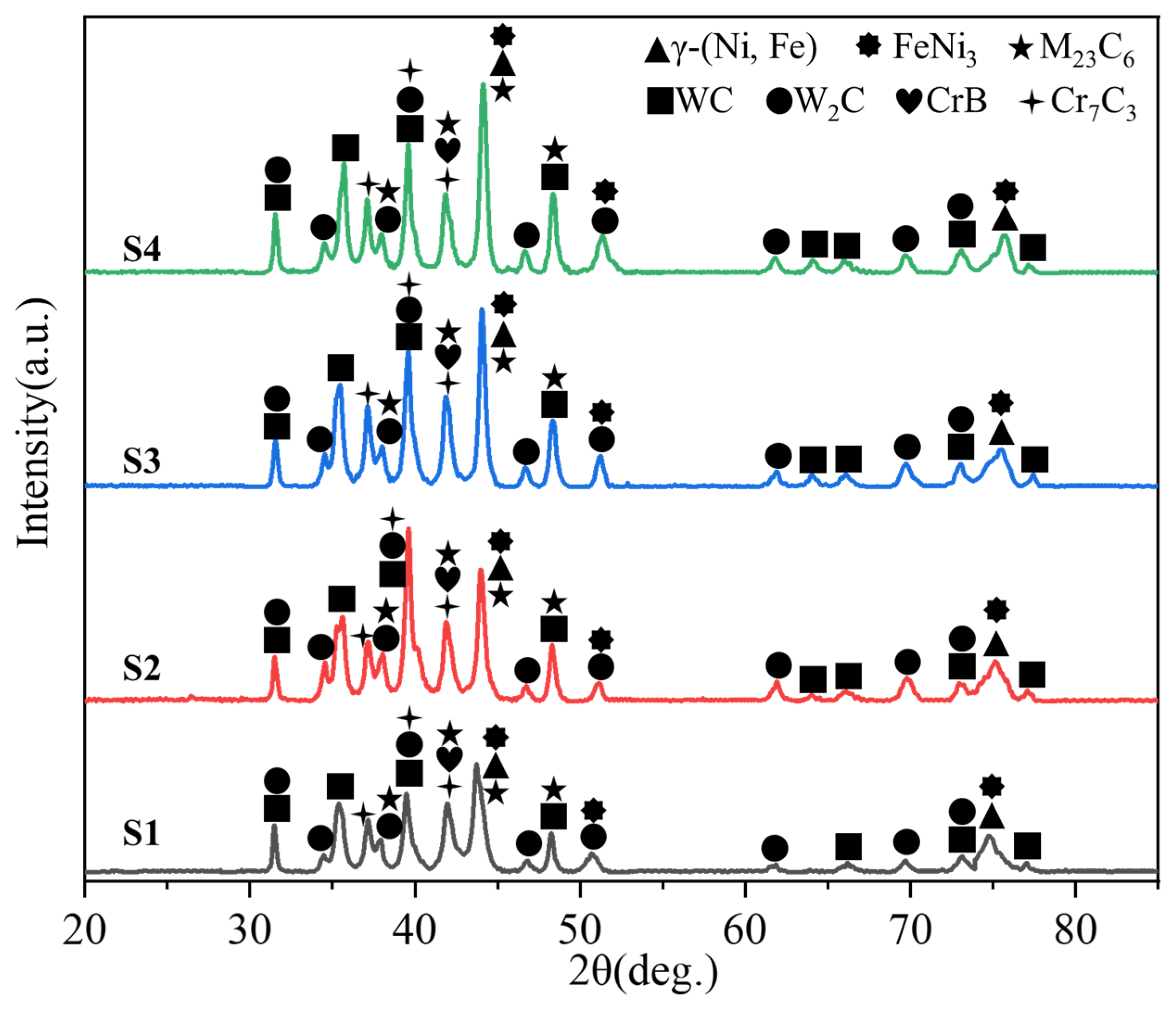
Figure 2 demonstrates the X-ray diffraction (XRD) patterns of Ni65A/WC composite coatings at different powers. The PDF cards for the different phases are as follows: WC-PDF#02-1055, W2C-PDF#02-1134, Cr7C3-PDF#11-0550, Cr23C6-PDF#35-0783, CrB-PDF#26-0420, FeNi3-PDF#88-1715, and γ(Ni, Fe)PDF#04-0850. At 800 W power, the XRD pattern shows that the diffraction peaks are of low intensity and the characteristic peaks of the enhanced phases are not significant. The diffraction peaks of matrix Ni and Fe were dominant and the peak width was large. This indicates that the melting pool temperature is insufficient and the reinforcing phase may not be fully involved in the reaction. Only some substances in the form of unreacted particles precipitated in the middle and lower layers of the coating, with uneven distribution. The grains in the melt-coated layer are coarse, resulting in poor densification. This leads to limited reinforcement of the coating and poor wear resistance. At 1200 W power, the XRD pattern shows significant enhancement in the intensity of diffraction peaks. The characteristic peaks of the reinforced and secondary phases are clear and the peak width decreases, indicating that the densification and homogeneity of the coating organisation are better. Under this power condition, the dissolution and distribution of the reinforcing phase were optimised significantly and a better metallurgical bond was formed with the substrate. At the same time, a moderate amount of secondary phase was generated. The performance of the coating was significantly improved under this condition. However, the dissolution of some reinforcing phases may prevent them from fully exerting their strengthening effect, which results in slightly inferior performance compared to higher power conditions. At 1600 W, the XRD pattern shows a weakening of the characteristic peaks of the reinforcing phase and a significant enhancement of the characteristic peaks of the secondary phase. The broadening of the matrix peaks indicates that the high power in the pool promotes a large amount of dissolution of the reinforced phase and re-precipitation of the secondary phase. At the same time, the grains of the cladding layer are significantly refined, and the effect of fine-crystal reinforcement is obvious. Although the high temperature may lead to a slight decrease in homogeneity in local areas, the redistribution and refinement of the reinforcing phase is better than that of the 1200 W power condition, resulting in a further improvement in overall performance. The wear resistance and hardness of the coatings were optimised at this time. At 2000 W power, the XRD pattern exhibits a significant decrease in diffraction peak intensity and a substantial increase in peak width. The characteristic peaks of the secondary phase dominate, the reinforcing phase may be completely dissolved, and the tissue coarsening is obvious. The excessively high melt pool temperature leads to an increase in tissue defects (e.g., holes and cracks) and a significant decrease in the uniformity and densification of the fusion-coated layer. The coating primarily consists of coarse-crystalline tissue and numerous secondary phases, resulting in a significantly weakened strengthening effect and the worst performance. For this reason, as the laser power was increased from 800 W to 1600 W, the dissolution, re-precipitation, and secondary phase generation processes of the reinforced phase were gradually optimised. The densification, homogeneity, and overall performance of the coating were significantly improved. The 800 W power of the molten pool energy is insufficient due to the enhanced phases precipitation and uneven distribution. Under the condition of 1200 W power, the dissolution and distribution of the reinforcing phase were improved. However, some underutilised reinforcing phases remain, and while performance improvement is significant, it is not optimal. 1600 W power further improves the dissolution and precipitation of enhanced phases, and the generation of secondary phases increases. At the same time, the grain refinement of the coating is obvious, meaning that the coating performance reaches the best level. At 2000 W power, the high melt pool temperature causes tissue coarsening and the number of simultaneous defects to increase. The reinforced phase is completely dissolved and it is difficult for the reinforcing effect to be exerted, and the performance decreases significantly. Therefore, the 1600 W power condition is the best choice to optimise the use of reinforcing phase, fine grain strengthening, and performance balance, while low power and too high power will lead to performance degradation.
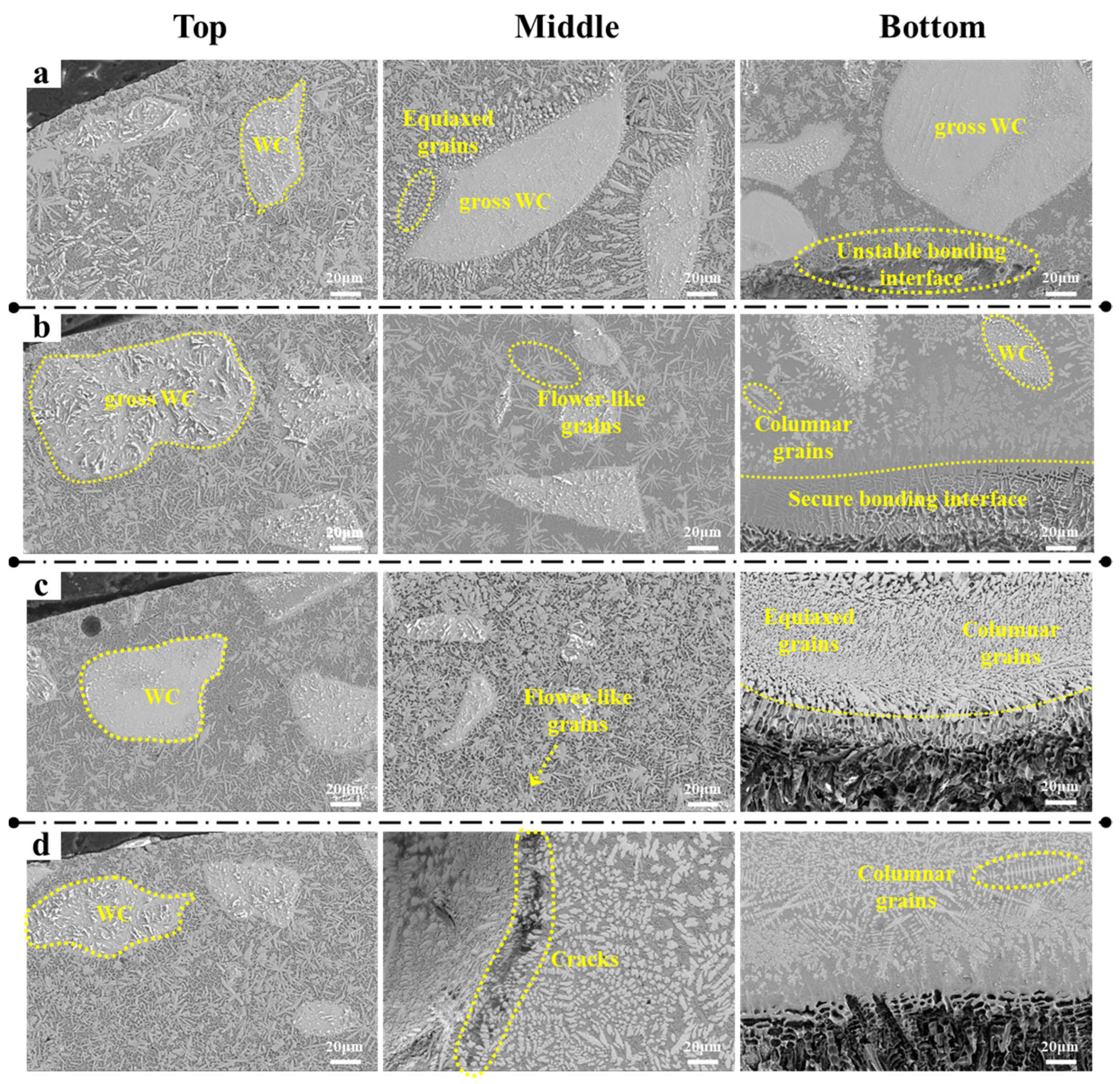
Figure 3 demonstrates the microstructure of the coating cross-section of the Ni65A/WC composite at different laser powers. As can be seen from the figure, the temperature of the molten pool in the top region is lower under the 800 W power condition. As a result, the reinforcing phase WC particles were not sufficiently dissolved in the pool melt and most of the particles were precipitated in the lower and middle layers of the coating. Due to the shortage of energy, the equiaxed crystals at the top are coarser, and the grain boundaries are indistinct. The particles were not uniformly distributed and high porosity was present. This phenomenon may be due to the poor fluidity of the melt pool, and the reinforcing phase could not be sufficiently diffused and uniformly distributed in the coating. The flower-like grains in the central region are sparsely distributed and have irregular grain boundaries. The reinforcing phase particles are partially concentrated in certain localised areas and the metallurgical bond with the substrate is weak. Under low-power conditions, the melt pool temperature is inadequate to provide sufficient driving force for redistributing the reinforcing phases. This resulted in the formation of significant inhomogeneities in the microstructure. The columnar crystals at the bottom are loosely arranged, and the grain size is large and without obvious direction. Since the reinforcing phase particles are mostly deposited in the bottom region, WC has a weak bonding interface with the substrate and cannot form a continuous and dense metallurgical bond [
30]. This indicates that the utilisation efficiency of the reinforcing phase is very low, and the mechanical properties of the coating are significantly limited under low-power conditions.
When the laser acting power is 1200 W, the temperature of the molten pool in the top region is moderate. The reinforcing phase particles can be partially dissolved and uniformly distributed in the coating, forming fine and regular equiaxed crystals. The grain boundaries are clear and the particles are uniformly distributed. This indicates that the moderate energy input improves the mobility and cooling rate of the melt pool, resulting in a significant increase in the organisational densification of the coating tip. At the same time, the porosity was significantly reduced. In the middle region, the flower-like grains are uniformly distributed and of moderate size, and the reinforcing phase particles are well dispersed and form a better reinforcing phase during the cooling process. This indicates that the partial decomposition of the reinforcing phase and the metallurgical bonding with the matrix resulted in a significant increase in grain boundary strength in the central region. At the same time, the tissue densification is good. This region is probably the part of the coating with the highest strength and wear resistance. The bottom columnar crystals are well aligned and fine-grained, and the bonding with the substrate interface is relatively tight. The moderate melt pool energy and fluidity ensure that the transition zone between the coating and the substrate is free of visible defects. The distribution of reinforcing phase particles here is also more uniform, effectively inhibiting the formation and expansion of cracks.
The equiaxed crystals in the apical region of sample S4 are significantly coarsened due to the excessively high melt pool temperature, resulting in the complete dissolution of the reinforcing phase particles and preventing the formation of effective reinforcing particles. This resulted in blurred grain boundaries and reduced densification. The excessive energy input triggered abnormal grain growth and structural degradation, indicating a significant decrease in the tissue-strengthening effect. The flower-like grains in the central region became coarse, and the grain boundaries were unclear, and the reinforcing phase failed to re-precipitate to form an effective reinforcing structure. Cracks and pores appeared in the organisation. This may be due to the grain growth and thermal stress concentration caused by prolonged heating at too high a temperature. The homogeneity and strength of the microstructure were further weakened. The arrangement of columnar crystals at the bottom is disordered and the grain size is significantly increased, and there are multiple cracks and delamination defects at the bonding interface with the matrix. The excessively high temperature leads to excessive mobility in the melt pool, which leads to compositional segregation. The reinforced phase particles are almost completely dissolved, leading to poor interface bonding and significantly reducing the overall mechanical properties of the coating [
31].
From the tissue evolution pattern of the coatings under different power conditions, it can be seen that the S1 specimen (800 W) failed to fully dissolve the reinforcing phase due to the insufficient melting pool temperature. The organisation of the coating is coarse and unevenly distributed, with pores at the top. The enhanced phase precipitation in the middle is uneven. The bottom bonding interface is poor, resulting in the lowest coating performance. Under S2 (1200 W) conditions, the melt pool temperature is moderate. The reinforcing phase is partially dissolved and uniformly distributed, forming fine equiaxial crystals, flower-like grains, and neat columnar crystals. The tissue densification was high and the properties were significantly improved. S3 (1600 W) further increased the melt pool temperature, and the reinforcing phase was completely dissolved and re-precipitated to form reinforcing particles, and the grains were significantly refined. The top, middle and bottom of this coating show excellent densification and homogeneity. S4 (2000 W), on the other hand, has a high melt pool temperature, resulting in grain coarsening, cracks and interface defects. The reinforcing phase was not redistributed after decomposition, and the densification and homogeneity of the coating decreased significantly, which resulted in the worst performance.
Under the 800 W power condition (
Figure 4), the insufficient melting pool temperature resulted in the formation of a clear dendritic structure of the coating, with coarse and strongly orientated grains. At the same time, the reinforcing phase WC particles were not sufficiently dissolved and exhibited deposition. The SEM morphology shows that the coating structure is rough and the reinforcing phase is not fully integrated with the substrate, resulting in poor overall densification. This leads to overall poor densification. Elemental distribution analysis shows that Ni and Fe are uniformly distributed as matrix elements. However, W and C in the reinforced phase show uneven distribution with high local concentrations. This indicates that the WC particles are not fully involved in the metallurgical reaction. In addition, the Cr element may have a slight enrichment phenomenon at the grain boundary. The insufficiency under low power conditions resulted in a coarsened and weakly bonded coating organisation, which is presumed to have poor mechanical properties. In particular, the hardness and wear resistance were poor. At 1200 W power with moderate melt pool temperature, the coating organisation was significantly optimised. It is primarily characterised by fine equiaxed crystals with uniform and regular grain arrangement. The reinforcing phase WC particles were partially dissolved and redistributed in the coating and were evenly dispersed inside the coating, which significantly improved the densification of the coating. SEM morphology showed that the surface of the coating was homogeneous with no obvious defects, and the reinforcing phase was well bonded with the substrate. The elemental distribution results show that Ni and Fe are stably and uniformly distributed, while W and C are also uniformly dispersed. The elemental distribution of Cr is stable and there is no grain boundary enrichment phenomenon. The results showed the optimisation of enhanced phase distribution and the enhancement of tissue densification under medium power conditions. The coating showed excellent performance in terms of hardness, wear resistance, and interfacial bond strength.
Under 1600 W power conditions, the coating exhibits a more refined microstructure, with fine equiaxed crystals dominating at the surface. SEM morphology shows that the reinforcing phase WC particles are completely dissolved in the high-temperature melt pool. During the cooling process, the grains re-precipitate uniformly as fine particles, resulting in a remarkable strengthening effect. The grain distribution in the middle region is relatively more uniform, and the dissolution and precipitation of the reinforcing phase reaches the best and most excellent state. A dense and tightly bonded microstructure is formed, and the bonding strength between grain boundaries is greatly improved. The columnar crystals in the bottom area are closely arranged, the grains are refined, and the bonding effect between the coating and the substrate is excellent. The interface transition is smooth without obvious defects. Elemental distribution analysis shows that Ni, Fe, and Cr are uniformly distributed, and W and C are also uniformly dispersed. This shows that the reinforcing phase is fully utilised. The higher power fine grain strengthening and the optimised distribution of reinforcing phases resulted in the best organisational densification and homogeneity of the coating. The hardness, wear resistance, and overall performance are presumed to be the best among the four groups of samples. At 2000 W, the high melt pool temperature had a significant negative effect on the coating organisation. Coarse equiaxial crystals appeared in the apical region, with blurred grain boundaries and obvious orientation. The reinforcing phase WC was completely dissolved but failed to precipitate uniformly, resulting in poor distribution of the reinforcing phase particles in the organisation and significant weakening of the strengthening effect. The flower-like grains in the middle region are coarsened with blurred grain boundaries, and SEM morphology reveals cracks and pores inside the coating. This indicates that the high temperature leads to a change in the concentration of thermal stresses and an increase in organisational instability. The columnar crystal arrangement in the bottom region is disordered, the grain size increases, and the interfacial bonding defects are obvious. Although the matrix elements Ni and Fe are uniformly distributed, the distribution of W and C in the reinforcing phase is uneven, with potential segregation phenomena. The role of the Cr element is weakened and cannot show the strengthening effect, and the overall densification and uniformity of the coating are greatly reduced. The grain coarsening and structural defects under excessively high power conditions result in a significant decrease in the hardness, wear resistance, and interfacial bonding strength of the coating, making its performance the worst among the four groups of samples.
Therefore, from the performance of the coating organisation and properties under different power conditions, the low power (800 W) resulted in uneven distribution of the reinforcing phase due to the insufficient melting pool temperature. The coating forms a coarse dendritic structure with poor densification and mechanical properties. The medium power (1200 W) coating is dominated by fine equiaxial crystals, and the reinforcing phase is uniformly dispersed after partial dissolution, resulting in better densification and uniformity of the coating. The performance is significantly improved. The higher-power (1600 W) coating has the best effect of fine crystal reinforcement. The reinforcing phase is completely dissolved and re-dispersed uniformly to form an optimised dense structure. The hardness and wear resistance are presumed to be at an optimum level. Too high power (2000 W) leads to grain coarsening, cracks and defects, and reduced utilisation of the reinforcing phase due to the high melt pool temperature. The homogeneity of the coating organisation and mechanical properties deteriorated. Therefore, medium-to-high power (1200 W–1600 W) is the key condition to achieve coating organisation optimisation and performance enhancement, with the 1600 W coatings showing the best performance.
3.2. Friction and Microhardness
Figure 5 demonstrates the cross-sectional hardness distribution curves (a) and the average microhardness values (b) of the laser fusion-coated coatings under different power conditions (S1, S2, S3, and S4). By analysing the effects of different power conditions on the hardness of the coating area (Coating), fusion zone (FZ/HAZ), and substrate (Substrate), the contributions of microstructure, densification, and enhanced phase distribution of the coatings to the hardness can be inferred for different process parameters. From the hardness distribution curve in
Figure 5a, it can be observed that S1 has a hardness of 236.5 HV in the Substrate region, and the hardness of the coating gradually increases. However, the curve is flat, and the maximum hardness is significantly lower than that of the other power conditions (about 353 HV). This indicates that under low power conditions, the melt pool temperature is insufficient and the reinforcing phase WC particles are not sufficiently decomposed and uniformly distributed. The densification and homogeneity of the coating are poor, the grains are large, and they lack the support of the reinforcing phase. As a result, the hardness of the coatings, although increased compared to the substrate, showed a limited strengthening effect. For S2, the hardness of the coatings increases rapidly until the surface hardness reaches approximately 375 HV, showing a significant hardening effect. The curve is smoother in the Coating zone and the hardness distribution is uniform. This indicates that the reinforcing phase WC is partially decomposed and uniformly dispersed in the coating under medium power conditions, forming a good metallurgical bond with the substrate. At the same time, the high melt mobility and rapid cooling promote the formation of fine grains, and the organisational homogeneity and densification of the coating are significantly improved. As a result, the hardness is significantly enhanced and uniformly distributed. The maximum hardness of the S3 coating is about 365 HV, which is slightly lower than that of S2. However, the distribution of hardness is more uniform, and the hardness gradient between the fusion zone and the coating is less variable. For this reason, the reinforcing phase WC was completely dissolved and re-precipitated into fine particles under higher power conditions, forming a uniformly distributed reinforcing phase. At the same time, the coating grains were significantly refined, which further enhanced the coating hardness. However, some areas may be slightly coarsened due to the high power, resulting in a slightly lower coating hardness than S2. The hardness of the S4 coating reached about 337 HV, which is significantly lower than that of S2 and S3, and the hardness distribution curve is not smooth and shows inhomogeneity. This shows that the high melt pool temperature under too high power conditions led to grain coarsening and complete decomposition of the reinforcing phase WC. However, it fails to precipitate uniformly and defects (e.g., pores and cracks) may appear in the coating, which significantly reduces the densification and hardness of the coating. In addition, the inhomogeneity of the microstructure leads to large fluctuations in hardness in the coating area, which weakens the overall strengthening effect of the coating.
By analysing the average microhardness histogram in
Figure 5b, it can be seen that there is a significant difference in the coating hardness under different power conditions. The average microhardness of the S1 specimen is 353.1 HV, representing an improvement over the hardness of the substrate. However, it is still the lowest hardness among the four groups of samples. The reason is that the melting pool temperature is insufficient, the reinforcing phase WC is not fully decomposed, and the densification and homogeneity of the coating are poor. The average microhardness of the S2 specimen is 375.4 HV, which is the highest among the four groups of specimens. The average microhardness of the S2 specimen is 375.4 HV, indicating that the utilisation rate of the reinforcing phase and the coating’s densification reach their optimal level under medium power conditions. The average microhardness of S3 is 365.2 HV, which is slightly lower than that of S2, but still significantly higher than that of S1 and S4. The strengthening effect of the reinforcing phase, which is completely dissolved and uniformly precipitated, is evident; however, the microstructure may be slightly coarsened in some areas due to the high power. The average microhardness of the S4 specimen is 337.8 HV, which is the second lowest among the four groups of coatings. It is much lower than S2 and S3. This indicates that grain coarsening and organisational defects (e.g., cracks and pores) under too high power conditions are the main reasons for the decrease in hardness. Also, the uneven precipitation of reinforcing phases further reduces the strengthening effect of the coatings.
From the hardness distribution curve and average microhardness analysis, it can be seen that the selection of power has a significant effect on the microstructure and hardness properties of the coating. Of note, 800 W (S1), due to the insufficient melting pool temperature, is responsible for the insufficient decomposition of the reinforcing phase, coarse grains, and poor densification, and thus, the hardness performance is the lowest. Moreover, 1200 W (S2) is the optimal condition, the reinforcing phase is uniformly dispersed, with fine grains, good densification, high hardness performance, and uniform distribution. The 1600 W (S3) coating fine crystal reinforcement effect is significant, but with local areas due to high temperature caused by slightly coarsened organisation. The 1600 W (S3) coating exhibits a significant fine-grain reinforcement effect; however, the organisation is slightly roughened in local areas due to the high temperature, resulting in hardness that is slightly lower than S2. The hardness is slightly lower than that of S2. 2000 W (S4) has a significant decrease in hardness due to grain coarsening and an increased number of defects caused by the high power. To summarise, 1200 W and 1600 W are the ideal power ranges for optimising the hardness properties of the coating.
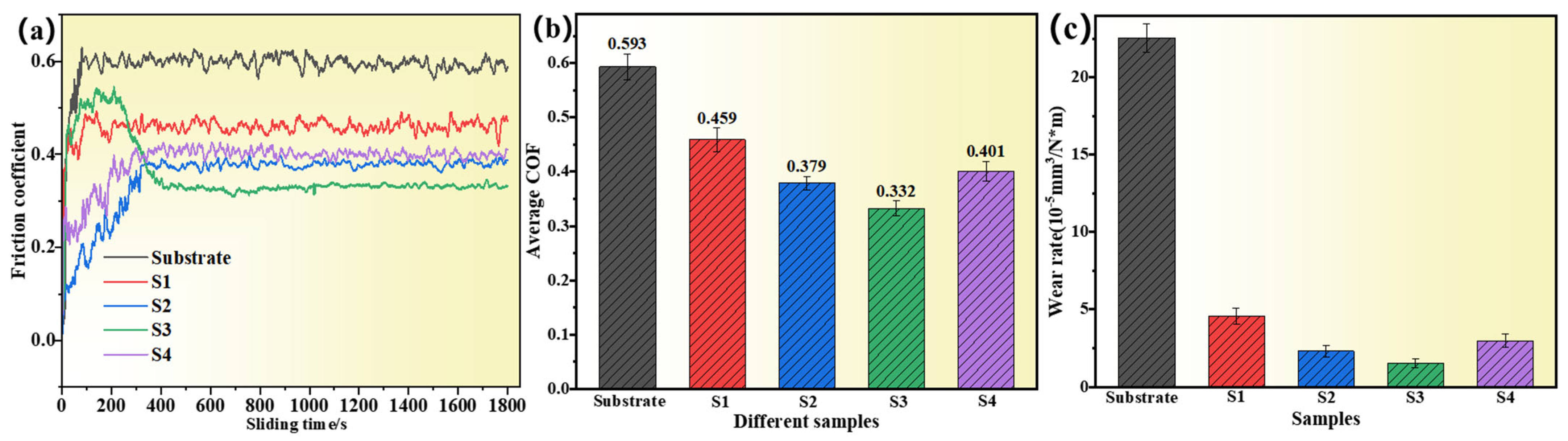
By analysing the sliding wear curves and the average coefficient of friction (COF) data during the static wear stabilisation stage for different specimens (S1, S2, S3, and S4) shown in
Figure 6, the effect of different laser power conditions on the wear resistance of the composite coatings can be deduced. Under the 800 W power condition, the molten pool temperature was insufficient, resulting in poor densification and homogeneity of the coating organisation. The reinforcing phase WC particles failed to dissolve sufficiently and showed local aggregation, with defects such as pores or microcracks potentially present in the coating. During the sliding wear process, the friction coefficient of S1 fluctuated initially and, after entering the stabilisation stage, remained at 0.459. Compared with the substrate (0.593), the friction coefficient was reduced. However, the enhancement was limited, and the wear process was less stable and showed a higher wear rate. The average coefficient of friction for static wear further verifies the limited improvement in wear resistance of S1. The poor performance was primarily due to the low power conditions failing to provide sufficient melt pool mobility and heat for the uniform dispersion of reinforcing phase particles. At 1200 W, the microstructure of the coating was significantly optimised, with the reinforcement phase WC particles partially dissolved and uniformly dispersed. Improved metallurgical bonding and reinforcing phases formed, and the densification and homogeneity of the coating were significantly enhanced. During the sliding wear process, the friction coefficient of S2 was significantly reduced to 0.379 and showed good curve stability, and the wear resistance of the coating was significantly enhanced. The static wear data showed a lower average coefficient of friction for S2. This indicates that the coating is optimised by the dissolution, uniform distribution, and microstructure densification of the enhanced phases under medium power conditions. A significant improvement in wear resistance was achieved. Thanks to the moderate melt pool temperature and uniform distribution of reinforcing phases, S2 exhibits excellent wear resistance. Friction and material loss were significantly reduced. It is one of the more desirable coatings in terms of performance.
At 1600 W laser power, the coating’s microstructure is further optimised, with an ideal melt pool temperature and fluidity. During cooling, the reinforced phase particles form a dense, well-distributed structure, while the coating grains are significantly refined. The lowest friction coefficient of 0.332 was observed for the S3 specimen during the sliding wear test. Notably, the friction curve of S3 initially increased and then decreased. This is attributed to the adhesion effect caused by local high temperature and pressure at the onset of friction, which temporarily elevated the friction coefficient. Over time, however, the coating surface stabilises into a slight plowing wear mechanism, resulting in a lower and more stable friction coefficient. From a mechanical and stress mechanics perspective, the 1600 W coating exhibited a low wear rate and friction coefficient during wear testing. This can be attributed to the high-strength support network formed by the reinforcing phase within the coating, which effectively disperses frictional stresses and minimises localised plastic deformation. Additionally, the dense coating structure enhances bonding between the hard phase and substrate, improving the overall mechanical stability. The refined grain structure and uniform distribution of the hard phases effectively inhibit crack propagation and reduce local stress concentrations, further enhancing the material’s mechanical properties.
At 2000 W, the excessive melt pool temperature caused the reinforcing phase WC particles to completely dissolve but failed to re-precipitate uniformly. The microstructure of the coating was coarsened and the uniformity was reduced. The friction coefficient of S4 during sliding wear is 0.401, which is slightly higher than that of S3, but it is still better than that of S1 and S2, and the curve stability is better. However, the wear resistance decreased. The average friction coefficient of static wear further indicates that the wear resistance of S4 is suboptimal. The main reason for this is that high power leads to grain growth and an increase in cracks, pores, and other defects in the organisation, which weakens the densification and wear resistance of the coating. Although high-power conditions still have a certain enhancement effect, the coating performance began to deteriorate significantly, as evidenced by reduced wear resistance and increased material loss.
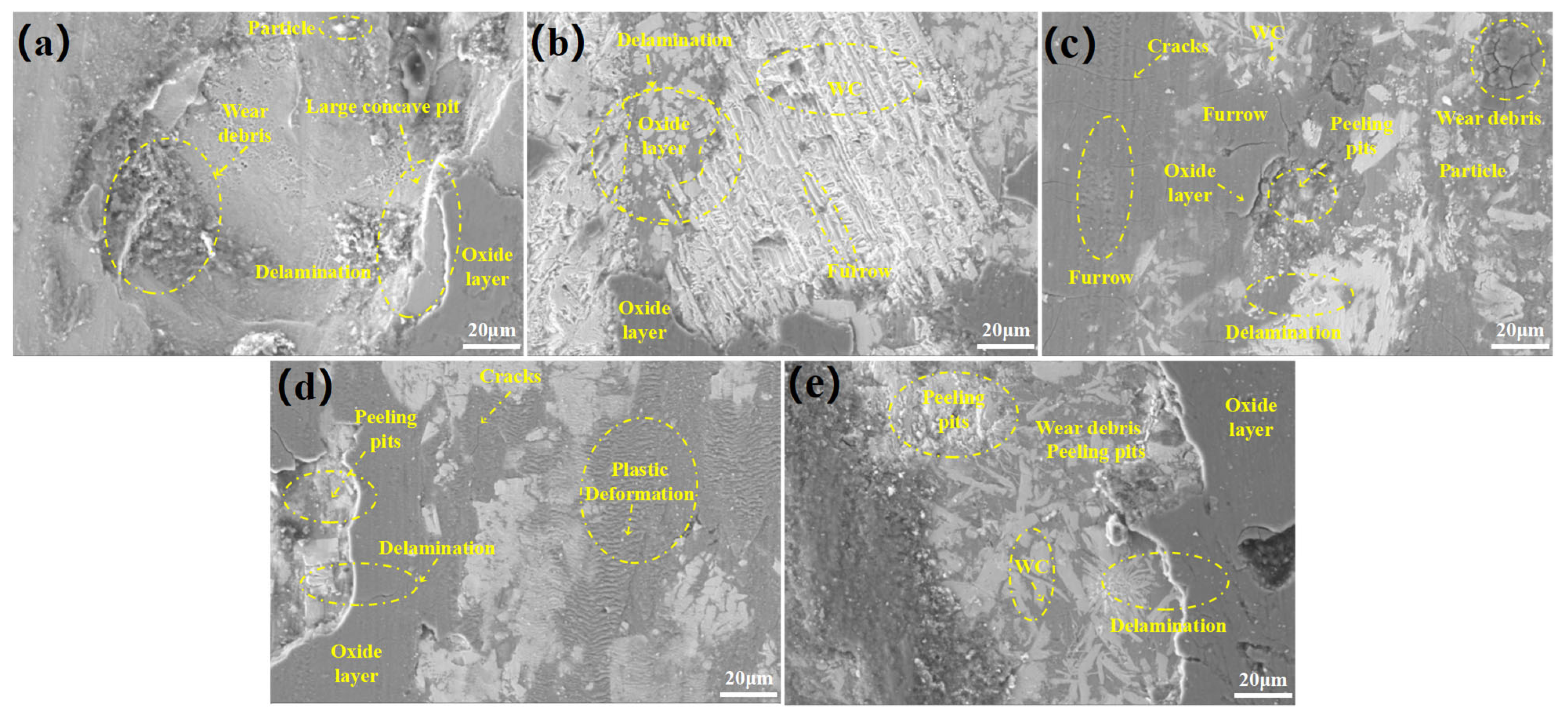
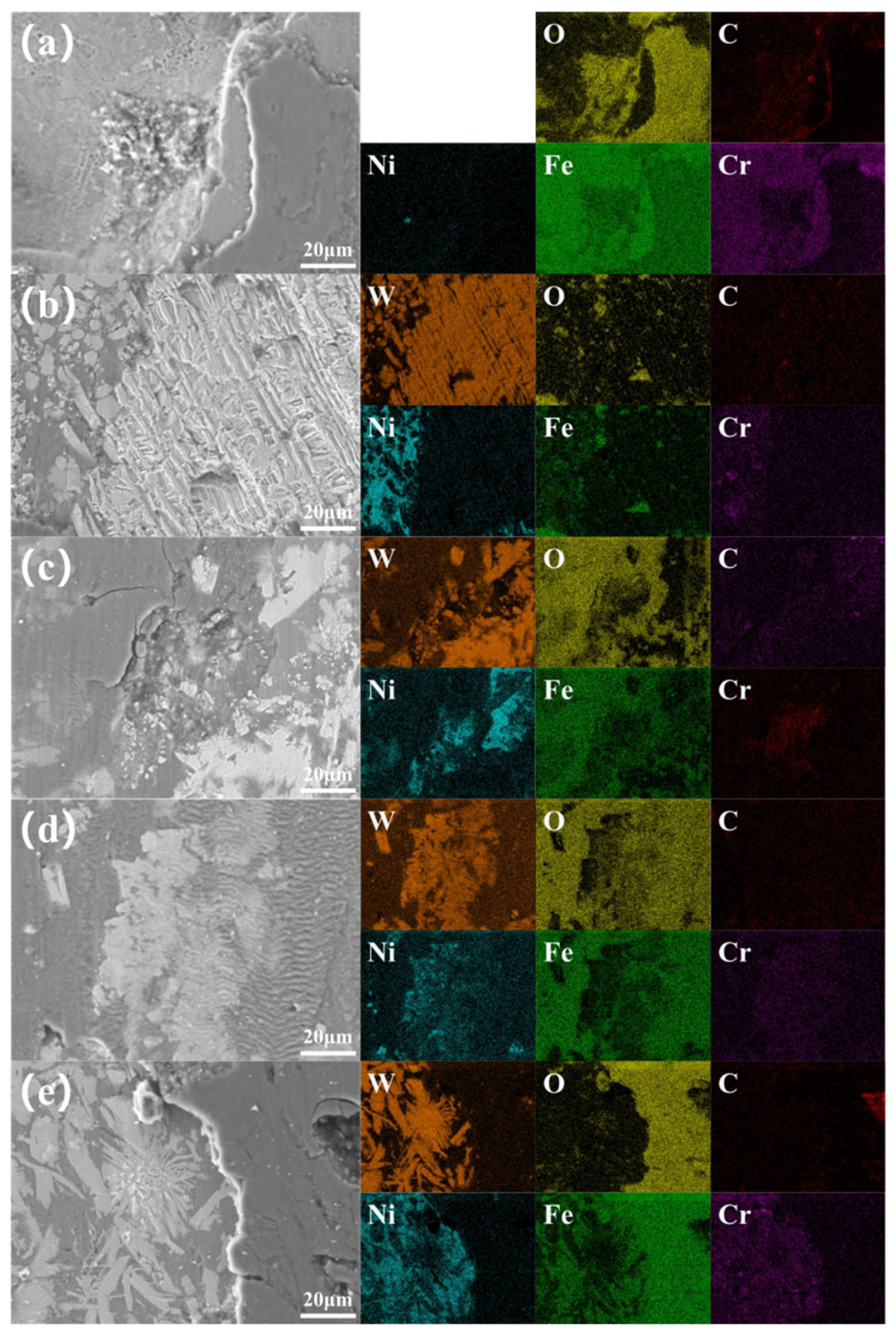
Figure 7 demonstrates the SEM images of different specimens after friction. The matrix material shows significant adhesive wear and plastic deformation during the friction process. This indicates that the wear resistance is extremely poor, and the surface material is shed on a large scale due to the local stress concentration during the wear process. The oxide layer is weak and unable to form effective protection at high temperatures. The fusion coating at 800 W power has limited densification and uniformity due to the insufficient melt pool temperature. Significant delamination, grooves, and flaking pits occurred, and the oxide layer was discontinuous. Although the performance was slightly improved compared to the substrate, it was still insufficient to effectively improve the wear resistance. The organisational homogeneity and densification of the coatings were significantly improved at 1200 W power. The distribution of reinforcing phases was more uniform. The surface wear characteristics were dominated by shallow grooves and a few abrasive particles. At the same time, a continuous oxide layer is formed as a protective barrier, which significantly improves the wear resistance. The melt coating exhibits optimal performance and forms the densest structure when the reinforcing phase is fully dissolved and precipitated at a laser power of 1600 W. Slight abrasive wear is dominant on the surface, and the oxide layer is uniform and stable, effectively protecting the coating material. Excellent wear resistance was demonstrated. However, due to the high melt pool temperature at 2000 W, the coating organisation was coarsened and the densification decreased. With the discontinuity of the oxide layer, cracks and delamination phenomena increased significantly, leading to the deterioration of the wear resistance of the coating, which was manifested by more abrasive particles and spalling pits.
The matrix material in
Figure 8a shows obvious oxidation characteristics. The low content of C and Cr indicates that the matrix material has poor wear and oxidation resistance during friction. Oxidative wear and adhesive wear mainly dominated. This is primarily due to the low carbon (C) content in the Ni65A base material, which results in insufficient hard phase and solid solution strengthening. This makes it difficult to form a stable oxide film, leading to internal oxidation and a weakening of both wear resistance and oxidation resistance. Additionally, the low chromium (Cr) content reduces the formation of reinforcing phases, weakening the substrate’s strength. At the same time, it hampers the formation of a dense oxide film and reduces its stability, further compromising wear resistance and oxidation resistance.
Figure 8b shows that the 800 W coating reinforcing phase WC failed to dissolve sufficiently. Tungsten (W) and carbon (C) are not uniformly distributed. Ni and Fe are mainly distributed in the matrix region. This shows that the coating densification is insufficient under low power conditions and there are more pores and cracks in the microstructure. This leads to limited improvement in anti-wear performance.
Figure 8c, for the 1200 W coating, reveals the characteristics of uniform distribution after partial dissolution of the reinforcing phase WC. Tungsten (W) and carbon (C) are uniformly dispersed, oxide distribution is reduced, and the Ni and Fe matrix elements show good homogeneity. The overall densification is significantly improved, and the wear resistance and oxidation resistance of the coating are significantly enhanced. As shown in
Figure 8d, the 1600 W coating reaches the optimum microstructural state, and the reinforcing phases are completely dissolved and uniformly precipitated. This indicates an optimum density and homogeneity of the coating organisation. The anti-wear and anti-oxidation properties are excellent.
Figure 8e, for the 2000 W coating, shows uneven precipitation of reinforcing phases and coarsening of the tissue due to high power. Oxides increased and cracks and pores were significant.


