Abstract
This paper addresses ballistic protection, which is an important element in the performance of any military equipment. Improving ballistic properties is a necessity for individual protection through the use of protective vests. In this study, plasma jet thermal deposition was performed on ballistic protection materials, steel plates from the ARMOX category, using both metallic and ceramic powders. The samples with appropriate dimensions, covered with these types of powders, were analyzed from a microstructural point of view to determine their mechanical properties and evaluate the improvement in ballistic protection level. Microstructural analyses by optical and electronic microscopy, SEM (Scanning Electron Microscopy), allowed the performance of complex analyses regarding the adhesion of the deposits to the base material. It was possible to evaluate the microstructure, thickness, uniformity, and porosity of the deposits and the microstructural aspects at the interface between the base material and the deposit. For the efficient use of these deposits, tribological studies were carried out on the mechanical properties through scratch and microindentation analyses. The paper concludes the results obtained for the two types of deposits, metallic and ceramic, to streamline their use to increase the ballistic protection of bulletproof vests used in individual protection in military equipment.
1. Introduction
The primary protective shield for military personnel is a bulletproof vest. Improvement of material characteristics used for this type of application represents one of the main challenges regarding ballistic protection performance.
The bulletproof vest concept is correlated with the advent of firearms and implicitly the bullet, starting in the 17th century. Among the first bulletproof vest solutions, can be mentioned SN-42, developed during the interwar period. It was designed to provide ballistic protection against 9 mm steel-core bullets used for the MP-40 machine gun from a distance of approximately 150 m [1].
Military equipment, such as bulletproof vests, must guarantee ballistic protection through modern methods of increasing efficiency, such as by creating superficial coatings on the ballistic plates used in the construction of these vests, which must lead to a higher level of protection. Until now, ballistic plates have been made from materials known in this field, with hypereutectoid, high-alloy steels currently being used.
Previous studies regarding properties of ballistic protection materials [2], are showing that modern ballistic protection materials are divided into categories such as soft ballistic elements, for which are used materials such as para-aramid and high-performance polyethylene [3] and hard ballistic elements, for which are used ceramic materials (silicon carbide, aluminum oxide, boron carbide) [4], steel such as ARMOX steel plates [5], aluminum plates [6,7] or a set of bonded plates (which consists of aluminum, steel, ceramics and plastic materials) [8].
APS (Atmospheric Plasma Spray) has been used to apply coatings such as Co/Ni–TiCN multilayer coatings, using two layers, four layers, and a gradient layer on B4C ceramic matrix, evaluating the improvement of dynamic compressive properties of the material with deposited layers [4].
Miriam Lorenzo-Bañuelos [7] and collaborators applied Ni-Al metallic powder, Metco 450NS, using the APS deposition method on aluminum alloy series 5000. The impact of the deposition parameters, such as Argon gas flow, spraying speed and spraying distance, in relation to the mechanical properties of deposited samples by evaluating the Vickers microhardness, surface roughness, and SPT (Small Punch Test). Results are showing that the highest hardness was obtained by using an increased spraying distance combined with a lower spraying speed using a medium Argon flow rate.
Evren Özsahin [6] and his collaborators evaluated the influence of a protective layer subjected to high-speed impact loads on ballistic performances by applying two types of powders: a metallic powder, Metco 68F-NS-1, and a ceramic powder, Metco 201NS, to various types of aluminum alloys. Vicker microhardness properties of the resulting coatings and ballistic impact tests were performed on deposited samples and base material. The displacement of the back surface of the samples and the penetration depth of the front surface of the samples were measured. Improved results for the penetration depth of the front surface of the coated samples were observed for Metco 201NS powder, but the base material properties also have an important role in the results. Metco 68F-NS-1 coating showed an improvement in ballistic performance over the effects of ZrO2 coating, especially for higher impact velocities.
Lupu F.C. et al. [9,10] performed a research study for the improvement of material properties, using CS (Cold Spray) [11] deposition method, on 52100 steel material by applying NiCrC coatings, known under the commercial name of WIP-C1 [12] and an intermediate bond layer WIP-BC1, offering corrosion, wear and high temperature resistance. Microindentation and surface hardness test was performed on samples with deposited layers. Friction and corrosion properties of deposited layers have been evaluated. Results showed significant overall improvements in the mechanical and microstructural properties of the deposited samples, particularly for the corrosion rate parameter.
The present study exemplifies the major differences between the two powders used, Metco 42C and Metco 111, considering the base material’s mechanical properties. The evaluation of the base material exhibits already very good properties in comparison with the applied coating properties; nevertheless, based on previous research studies mentioned above, by applying thermal coatings using the APS deposition method, but using different types of powders and different base materials, major improvements of ballistic protection properties can be achieved.
This paper aims to be a basis for future ballistic tests, with the target to evaluate the impact of mechanical and microstructural properties of coated samples, to achieve a similar or improved ballistic protection level than already achieved by the base material, using decreased thickness of the base material. This leads to a decreased weight of the bulletproof vest equipment, but also to an economic benefit, given the reduced cost of the base material.
The base material chemical composition used in the present paper is from the ARMOX steel category. ARMOX steel plates [13] are produced by the Swedish company SSAB, utilizing iron ore-based metallurgy, through various manufacturing steps tailored to the required hardness properties. The hardness values vary between 280 and 640 BHN (Brinell Hardness Number), even higher for ARMOX Advance plates [14]. Chemical compositions of ARMOX plates are described in Table 1.

Table 1.
Chemical Composition (ladle analysis) in wt.% of ARMOX Ballistic Plates [13].
This study is contributing to the scientific progress in the field of material science, supporting the development of new modern materials with high ballistic protection properties for the military industry.
2. Materials and Methods
2.1. Characterization of Deposited Coatings
The coatings consisted of two types of powders, a metallic and a ceramic one. The metallic powder is commercially known as Metco 42C with the chemical composition Fe 17Cr 2Ni 0.18C and is martensitic, high chromium stainless steel powder similar to stainless steel type 431. The resulting coatings offer great wear and impact resistance in combination with the best corrosion resistance [15]. Metco 42C has particle sizes of −106 +45 µm and results in an irregular morphology, which can be sprayed in very thick layers. The morphological aspect of Metco 42C powders is represented in Figure 1.

Figure 1.
SEM image with morphological aspect of Metco 42C: (a) 50×, (b) 200×, (c) 500×.
The ceramic powder is commercially known as Metco 111, with the chemical composition TiO2 45Cr2O3. This powder was created for thermal deposition applications for the textile industry. The resulting coatings exhibit wear and hardness resistance in comparison with similar powders, but the addition of chrome oxide enhances the abrasion, wear, heat, and corrosion resistance and improves the hardness resistance [15]. Metco 111 has particle sizes of −63 +11 µm and offers an angular, blocky morphology, known also for dense, smooth, and relatively ductile coatings. Both Metco 42C and Metco 111 powders have a maximum service temperature up to 540 °C and are recommended for the APS deposition method. The morphological aspect of Metco 111 powders is represented in Figure 2.

Figure 2.
SEM image with morphological aspect of Metco 111: (a) 50×, (b) 200×, and (c) 2000×.
2.2. APS Thermal Deposition Method
To apply the powders described above, the APS thermal deposition method is used. This method occurs by creating an electric arc between two electrodes: a copper anode and a tungsten cathode, both of which are cooled by water. Between the two electrodes, a gas is introduced (hydrogen, nitrogen, helium, or gas mixtures). When the circuit is closed, an electric arc creates plasma by ionization and dissociation of the gases.
Plasma jet thermal coating is created when gas reaches temperatures of 7000 °C and even up to 10,000 °C, depending on the application.
Powder material is inserted into the spraying nozzle, and upon contact with the plasma gas, it is melted and propelled at high speed onto the support material, creating the surface coating.
Atmospheric Plasma Spray device schematic is presented below in Figure 3.
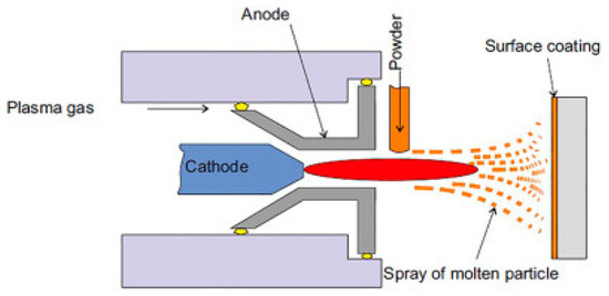
Figure 3.
Thermal coating plasma jet device [16].
2.3. Characterization of Thermal Deposition Process
Plasma jet thermal deposition process was performed using SPRAYWIZARD 9MCE (Sulzer Metco, Westbury, NY, USA) equipment from the Material Study Laboratory, part of the Mechanical Engineering Faculty, Iasi, Romania.
Before the thermal deposition process, samples were preheated up to 300 °C to reduce the thermal tension, which could lead to delamination of the coatings. The deposition temperature used for the current application was set to approximately 10,000 °C, and the spraying distance, between the spraying gun and sample, was set to 150 mm, for both powder applications.
The following operations have been performed for the deposition process:
- sample preparation;
- positioning of the samples on the support carriers;
- positioning of the support carriers on the fixture device;
- perform plasma jet process deposition using both powders;
- Clean up the powder tank after each deposition process.
As can be observed in Figure 4, sets of three individual samples of similar dimensions were prepared. Each set of three samples was used for the analysis defined in the chapter “Results”, after the coating layers were applied. Similar individual samples were prepared for the analysis of the base material as well. Sample numbering corresponds to one individual sample, out of the sets that were allocated for each analysis. The coating layers were applied in the same step for all samples.
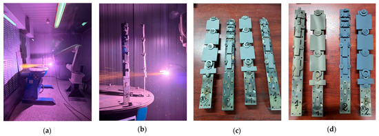
Figure 4.
Thermal deposition process overview: (a,b) thermal deposition process, (c) pre-deposited samples, (d) deposited samples.
2.4. Microstructural Properties Analysis
For the chemical composition evaluation of the base material, the Foundry Master Smart (Hitachi, Wetzlar and Mannheim, Germany) laboratory optical emission spectrometer was used, employing the spectrometry method to evaluate the wt.% elemental distribution.
To study the morphology of the surfaces, SEM (scanning electron microscopy) was used, and EDS (Energy Dispersive Spectroscopy) of deposited layers was performed using the Thermo Scientific Quattro C microscope, Brno, Czech Republic.
To perform the microstructural analysis, it was required to prepare samples by cutting using a Metacut 302 cutting machine, Metkon, Bursa, Turkey. The resulting samples underwent specific standard metallographic preparation operations, including grinding, cutting, polishing (using metallographic papers with grit sizes from P100 up to P2000, followed by polishing to a grit size of 0.25 µm) and chemical etching (for etching, was used a metallographic reagent based on alcohol and sulfuric acid), in order to obtain clear images with a comprehensible microstructure.
Sample embedding, required to secure the specimens on the grinding device, was conducted using an Ecopress 52 device, Metkon, Bursa, Turkey. Subsequently, grinding was performed utilizing the Forcipol 202 system, also from Metkon, Bursa, Turkey.
2.5. Mechanical Properties Analysis
Microindentation, microscratch, and friction testing were conducted using the UMTR 2M-CTR tribometer, version 1.122.245, and the UMT Test Viewer, CP4–2.16.93+ software.
Microindentation was used to determine the hardness of the base material and coated samples, according to the ASTM E18 standard [17]. For evaluation of the hardness value, a 120° ± 0.35° spheroconical Rockwell-type indenter was used, with a diamond tip, having a radius of 200 ± 10 µm, by applying a force up to 10 N, on sample surfaces. The indenter diamond tip has a modulus of elasticity of 1149 GPa and Poisson’s ratio of 0.07.
Microscratch resistance of base material and coated samples was determined according to ASTM D7187 standard [18].
Friction tests have been performed in translational motion, lasting for 60 min with a loading force of 10 N (the linear mass moving back and forth over a distance of 10 mm at a speed of 10 mm/s). Samples were tested using the CETR UMT-2 tribometer (Bruker, Billerica, MA, USA), following ASTM 132 standard [19], and for the test, a C45 steel pin with a diameter of 6.35 mm was used.
Friction tests in rotational motion lasted for 60 min with a loading force of 10 N, at a rotational speed of 60 rpm (corresponding to a peripheral speed of 125.66 mm/s). For the rotational motion test, the same type of steel pin was used as for the translational motion test, with a diameter of 6.35 mm.
3. Results
3.1. Microstructural Analysis of the Base Material
The SEM images presented in Figure 5 correlate with the chemical composition determined by spectrometry, as described in Table 2. It was found that the base material is a hypoeutectoid, low-alloy steel, and after moderate quenching/improvement, a sorbitic structure.

Figure 5.
SEM images of the microstructure of the base material: (a) 2000×, (b) 5000× and (c) 10,000×.

Table 2.
Chemical composition of the base material determined using the spectrometry method in wt.%.
3.2. Morphological Analysis of Deposited Coatings
SEM images are presented in Figure 6 and show the morphological aspect of the deposited coatings with metallic powder Metco 42C, which consists of Fe 17Cr 2Ni 0.18C. It can be observed that the layer is uniformly distributed, as evidenced by the presence of unmelted particles.

Figure 6.
Morphological aspect of the metallic layer deposited with Metco 42C. (a) 50×, (b) 100×, (c) 200×, (d) 500×, (e) 1000×, (f) 2000×, (g) 5000×, (h) 10,000×, (i) 50,000×, and (j) 100,000×.
As can be observed in Figure 7, the SEM image presents the morphological aspect of the deposited coatings with ceramic powder Metco 111, which consists of TiO245Cr2O3. It can be observed that the layer is uniformly distributed, without the presence of unmelted particles, as in the previous case, resulting in a smooth and dense coated surface.

Figure 7.
Morphological aspect of the metallic layer deposited with Metco 111. (a) 50×, (b) 100×, (c) 200×, (d) 500×, (e) 1000×, (f) 2000×, (g) 5000×, (h) 10,000×, (i) 50,000×, and (j) 100,000×.
3.3. EDS (Energy Dispersive Spectroscopy) Analysis of Deposited Coatings
In Figure 8, both the elemental distribution maps and the quantity of identified elements are shown for the deposited surface. The wt% (weight percent) higher distribution can be observed in Figure 8a for the Cr element for Metco 42C powder. As can be observed in Figure 8b, for Metco 111 powder, a higher distribution of wt% (weight percent) was identified for the Ti element.
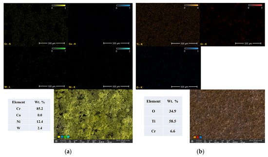
Figure 8.
EDS Analysis of deposited coating with: (a) Metco 42 C and (b) Metco 111.
3.4. Adhesion Analysis of Deposited Coatings
The adhesion of the deposited Metco 42C layer to the base material was assessed through SEM analysis. Partial adhesion of the deposited layer can be observed. Porosities and imperfections are present at the interface due to the entrapment of gases and not melted particles. The average thickness of the deposited layer is approximately 150 µm.
The cross-sectional view and thickness measurement of the deposited layer are presented in Figure 9.

Figure 9.
Cross-sectional view of the deposited layer with Metco 42C: (a) 100×, (b) 500×, and (c) 2000×.
The cross-sectional view of the Metco 111 is presented in Figure 10.

Figure 10.
Cross-sectional view of the deposited coatings with Metco 111: (a) 100×, (b) 500×, and (c) 2000×.
Compared to the previous metallic coating, the ceramic coating, Metco 111, shows a substantial improvement in the adhesion of the layer to the base material. The average thickness of the deposited layer is approximately 80 µm.
3.5. Mechanical Properties Analysis
3.5.1. Microindentation Tests—Hardness Analysis
To evaluate the hardness and Young’s modulus of elasticity, microindentation tests were performed on three coated samples with Metco 42C, three samples coated with Metco 111 and one uncoated base material sample. All samples were tested with a maximum force of 10 N, and three microindentation tests were carried out for each load.
Figure 11 shows the resulting graphs for coated samples with Metco 42C and Metco 111, as well as for the base material sample.
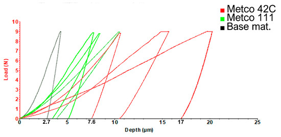
Figure 11.
Microindentation graphs: red—Metco 42C, green—Metco 111, black—base material.
The resulting data of microindentation tests are presented in Table 3, and it can be observed that the ceramic layer Metco 111 exhibits higher hardness values than the metallic layer Metco 42C. In comparison, the Metco 111 achieved a maximum value of 1.25 GPa, while the hardness values of the base material achieved 2.07 GPa.

Table 3.
Microindentation hardness test results according to the ASTM E18 standard [17].
Considering the results presented in Table 3, the base material exhibits greater hardness properties compared to deposited coatings, indicating enhanced wear resistance.
3.5.2. Microscratch Tests—Scratch Resistance
All samples exhibit good resistance to microscratching, as the variation of the COF (coefficient of friction) as a function of displacement on the Y-axis, shows numerous peaks and average mean values above 0.4.
In Figure 12, the X–axis represents the variation of the COF value, the Y-axis represents the displacement length in units of millimeters for the traveling of the measurement device moving over a distance of 10 mm on the sample surface. During this movement, a linearly increasing force from 1 N to 10 N, at a speed of 0.167 mm/s.
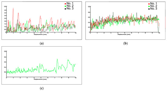
Figure 12.
Microscratch Graphs: (a) Metco 42C, (b) Metco 111, and (c) base material.
Microscratch data obtained after performing tests are presented in Table 4; the mean values of COF are higher for Metco 42C in comparison with Metco 111, with the lowest value being generated by the base material.

Table 4.
Microscratch mean COF values obtained through linear sliding tests according to the ASTM D7187 standard [18].
SEM pictures of microscratch test samples are presented in Figure 13. It can be observed that the Metco 42C sample has a microscratch path width up to 221.6 μm, and for Metco 111, a maximum width of 125.7 μm. Microscratch tracks are visible only on the deposited layer. We can see that the microscratch blade only removes the large asperities of the coating, with the base material not being exposed. Samples with scratch marks of lower depth and width values show a higher potential for microscratch resistance.

Figure 13.
SEM pictures of microscratch test samples: (a) Metco 42C 100×, (b) Metco 42C 500×, (c) Metco 111 100×, and (d) Metco 111 500×.
3.5.3. Friction Tests—Translational Motion
All coated samples with both types of powders have similar COF values (0.6), slightly higher than the COF of the base material (0.5).
The resulting graphs are presented in Figure 14, the X-axis represents the variation of COF values, and the Y-axis represents the unit of time in seconds, regarding the duration of the friction translational test on the surface of the test samples. Test parameters considered for the translational movement over a defined time unit, represented on the Y-axis, include a loading force of 10 N applied to the measurement pin, which moves back and forth over a distance of 10 mm at a speed of 10 mm/s. The obtained mean COF values resulting from the performed tests are presented below in Table 5.
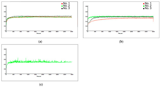
Figure 14.
Friction test graphs—translation motion: (a) Metco 42C, (b) Metco 111, and (c) base material.

Table 5.
Friction translation motion resulted in the mean COF values obtained according to the ASTM132 standard [19].
From the SEM images shown in Figure 15, we can observe that the peaks of asperities were removed and the particles are remaining on the sliding track, resulting in an abrasive behavior that leads to higher COF values. Comparing with base material results, coated samples are showing slightly improved COF values, which translates into improved wear resistance of coated samples.

Figure 15.
SEM pictures of translational friction test samples: (a) Metco 42C 100×, (b) Metco 42C 500×, (c) Metco 111 100×, and (d) Metco 111 500×.
3.5.4. Friction Tests—Rotational Motion
The samples coated with Metco 42C powder exhibit lower COF values (0.6) compared to the samples coated with Metco 111 powder (0.7), but slightly higher than the COF of the base material (0.5).
The resulting graphs are presented in Figure 16, where the X-axis represents the variation of COF values and the Y-axis represents the unit of time in seconds, regarding the duration of the friction rotational test on the surface of the test samples. Test parameters considered for the rotational movement over a defined time unit represented in the Y-axis are a loading force of 10 N applied on the measurement pin, at a rotational speed of the test sample of 60 RPM (revolutions per minute), which, in relation to the point of contact, corresponds to a peripheral speed of 125.66 mm/s.
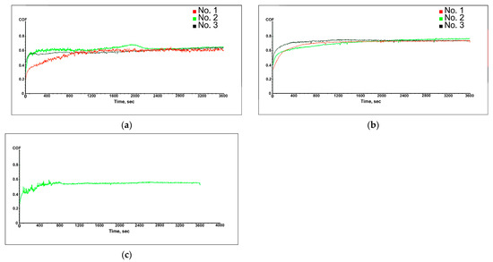
Figure 16.
Friction test graphs—rotational motion: (a) Metco 42C, (b) Metco 111, and (c) base material.
The obtained mean COF values resulting from the performed tests are presented below in Table 6.

Table 6.
Friction rotational motion resulted in mean COF values obtained according to the ASTM132 standard [19].
Metco 111 samples are showing higher COF values, and as can be observed in the SEM images shown in Figure 17, the Metco 111 coating exhibits a lower granularity of asperities, leading to higher COF values.

Figure 17.
SEM pictures of rotational friction test samples: (a) Metco42C 100×, (b) Metco 42C 500×, (c) Metco 111 100×, and (d) Metco 111 500×.
Metco 42C-coated samples achieved similar COF values as for translational motion tests. Compared to the base material properties, Metco 111 samples exhibit the highest COF values, which translates into improved wear resistance.
4. Discussion
Considering the friction test results for translational and rotational motion, presented in the current study (0.6 to 0.7), using similar test standards, results show similar COF mean values for deposited samples using WIP-C1 powder applied with different deposition methods (CS) and using different base materials, 52100 steel [9,10]. WIP-C1 powder composition contains ingredients such as Cr (59–76 wt.%), C (2–5 wt.%) and Ni (22–36 wt.%) and is specifically used for wear and impact/corrosion resistance applications using the Cold Spray deposition method.
The metallic Metco 42C iron base used in the present study contains ingredients such as Fe (Balance wt.%), Cr (17 wt.%), Ni (2 wt.%) and C (0.18 wt.%), which offer fair wear resistance, impact strength and corrosion resistance.
The ceramic Metco 111 utilized in the present study contains ingredients such as TiO2 (balance wt.%) and Cr2O3 (44–46 wt.%), which improve hardness and enhance the abrasion, wear, heat and corrosion resistance in comparison with other ceramics.
Considering the obtained friction test results for deposited samples, by utilizing powders that exhibit wear and impact resistance properties, regardless of the utilized deposition method, it can be observed that we can obtain improved results with a positive impact for ballistic protection applications.
Ceramic Metco 201NS, used by Evren Özsahin [6] and his collaborators, presented improved results for the ballistic impact test penetration depth of the front face surface. Metco 201NS contains ingredients such as ZrO2 (91.5 wt.%), CaO (4.5–5.5 wt.%), and other oxides. Considering that zirconium-based ceramic powder has shown improved results in ballistic tests, the present study has decided to utilize Metco 111 titanium oxide-based ceramic powder. Titanium’s lower density combined with its high strength gives it a superior strength-to-weight ratio compared to zirconium, making it a great choice for reduced weight applications such as bulletproof vests. Compared with other ceramic powders, Metco 111 exhibits higher impact resistance and fracture toughness than Metco 106NS chromium oxide base powder.
Metallic powder Metco 68F-NS-1 tribaloy type, used by Evren Özsahin [6] and his collaborators, exhibits better ballistic performance compared with ceramic powder for higher impact velocities. This powder contains ingredients such as Co (49.4 wt.%), Mo (28.5 wt.%), Cr (17.5 wt.%) and Si (3.4 wt.%). For the present study, the metallic powder Metco42C has been utilized considering its impact resistance properties combined with its very thick sprayed layer.
For further evaluation of the ballistic protection properties in relation to the obtained results of the present study and in reference to available evaluations presented in the literature, ballistic impact tests are recommended to be performed.
5. Conclusions
- The thermal spray deposition technology using a plasma jet successfully enables the formation of surface coatings on materials used for ballistic protection.
- Despite the similar deposition temperature used for both powder applications, cross-sectional microstructural analyses have revealed that the coating with the highest resulting thickness, using Metco 42C metallic powder, achieved the worst adhesion on the base material, in comparison with the Metco 111 ceramic powder coating.
- Mechanical testing confirms that the coatings exhibit excellent resistance to micro-scratching. Furthermore, microstructural analyses performed after mechanical trials indicate that the deposited layers remain intact and do not suffer penetration.
- Microindentation tests are showing that base material hardness achieved a value of 2.07 GPa, while Metco 111 samples achieved a maximum value of 1.25 GPa, the lowest value being achieved by Metco 42C, with a maximum value of 0.72 GPa. Therefore, the recommended layer for the highest improvement of hardness properties of coated surfaces is achieved with Metco 111 ceramic powder.
- The microscratch test showed that Metco 42C has good sliding resistance, and at the same time, a higher COF value of 1.2. It is observed that the COF value decreases during the progression along the Y-axis displacement until the highest peaks of the asperities are removed. The resulting COF variations of the Metco 42C sample, reflect a higher value of surface roughness in comparison with the base material sample.
- For the translational motion friction test, a maximum COF value of 0.6 was obtained for the Metco 42C sample, similar to that of the Metco 111 samples. Both coated samples have higher COF values than the base material, which achieved a value of 0.5.
- For rotational motion, the friction test, on the other hand, the samples with Metco 111 achieved the highest COF value of 0.7, while Metco 42C achieved a COF value of 0.6, similar to that of the translational friction test. The base material achieved a COF value of 0.5, higher than the value obtained in the translational friction test. For improving rotational friction properties, Metco 111 ceramic powder is recommended for use. Considering the COF results of the friction test, which are slightly higher than the COF results of the base material, both powders offer improved wear resistance properties in comparison with the base material properties.
Author Contributions
Conceptualization, C.M. and A.N.R.; methodology, A.S.; software, M.B.; validation, B.I.; formal analysis, B.I. and A.S.; investigation, F.C.L.; resources, A.N.R.; data curation, A.I.R.; writing—original draft preparation, A.I.R.; writing—review and editing, F.C.L.; visualization, M.B.; supervision, C.M.; project administration, A.N.R.; funding acquisition, A.N.R. and C.M. All authors have read and agreed to the published version of the manuscript.
Funding
This work was supported by a grant of the Ministry of Research, Innovation, and Digitalization, CNCS-UEFISCDI, project number PN-IV-P6-6_3-SOL-2024-2-0254, within SOL-2024-24-Combatant Digital.
Data Availability Statement
The original contributions presented in this study are included in the article. Further inquiries can be directed to the corresponding author.
Conflicts of Interest
The authors declare no conflicts of interest.
Abbreviations
The following abbreviations are used in this manuscript:
| APS | Atmospheric Plasma Spray |
| CS | Cold Spray |
| SEM | Scanning Electron Microscopy |
| EDS | Energy Dispersive Spectroscopy |
| COF | Coefficient of friction |
| SPT | Small Punch Test |
| BHN | Brinell Hardness Number |
References
- Romania Military. Available online: https://www.rumaniamilitary.ro/vesta-antiglont-ieri-si-azi (accessed on 28 May 2025).
- Ropotoae, A.; Istrate, B.; Munteanu, C.; Lupu, F. Usage of Thermal Coatings for the Improvement of Material Properties for Ballistic Protection in the Military Field. A Review. Bull. Polytech. Inst. Iași Mach. Constr. Sect. 2024, 70, 9–25. [Google Scholar] [CrossRef]
- Protection, M. Aramid vs. Polyethylene for Use in Bullet-Resistant Vests. Available online: https://mehler-protection.com/blog/aramid-vs-polyethylene-for-use-in-bullet-resistant-vests/ (accessed on 8 September 2024).
- Mi, P.; Liu, J.; Zhou, Z.; Zhao, H.; Qi, C.; He, J. The dynamic compressive properties of B4C ceramic by plasma spraying multilayer Co/Ni–TiCN coatings. Ceram. Int. 2023, 49, 6708–6712. [Google Scholar] [CrossRef]
- Showalter, D.; Gooch, W.; Burkins, M.; Koch, R. Balistic Testing of SSAB Ultra-High Hardness Steel for Armour Applications; ARL-TR-4632; Army Research Lab: Adelphi, MD, USA, 2008; 52p. [Google Scholar]
- Özsahin, E.; Tolun, S. Influence of surface coating on ballistic performance of aluminum plates subjected to high velocity impact loads. Mater. Des. 2010, 31, 1276–1283. [Google Scholar] [CrossRef]
- Lorenzo-Bañuelos, M.; Díaz, A.; Rodríguez, D.; Cuesta, I.I.; Fernández, A.; Alegre, J.M. Influence of Atmospheric Plasma Spray Parameters (APS) on the Mechanical Properties of Ni-Al Coatings on Aluminum Alloy Substrate. Metals 2021, 11, 612. [Google Scholar] [CrossRef]
- Tsirogiannis, E.C.; Daskalakis, E.; Vogiatzis, C.; Psarommatis, F.; Bartolo, P. Advanced composite armor protection systems for military vehicles: Design methodology, ballistic testing, and comparison. Compos. Sci. Technol. 2024, 251, 110486. [Google Scholar] [CrossRef]
- Lupu, F.; Munteanu, C.; Müftü, S.; Benchea, M.; Cimpoesu, R.; Ferguson, G.; Boese, S.; Schwartz, P.; Istrate, B.; Arsenoaia, V. Evaluation of the Wear Properties and Corrosion Resistance of 52100 Steel Coated with Ni/CrC by Cold Spraying. Coatings 2024, 145, 14. [Google Scholar]
- Lupu, F.C.; Munteanu, C.; Istrate, B.; Lupescu, S.C.; Ciubotaru, R.; Adrian, S. Structural analysis and mechanical properties of some coatings obtained by cold spray method. A review. IOP Conf. Ser. Mater. Sci. Eng. 2022, 1262, 012023. [Google Scholar] [CrossRef]
- Al-Mangour, B. Fundamentals of Cold Spray Processing: Evolution and Future Perspective. In Cold-Spray Coatings: Recent Trends and Future Perspectives; Springer: Cham, Switzerland, 2018; pp. 3–24. [Google Scholar] [CrossRef]
- Solvus Golbal. Powers on Demand. 2024. Available online: https://order.powdersondemand.com/ (accessed on 8 September 2024).
- Product Offer and Datasheets. 2025. Available online: https://www.ssab.com/en/brands-and-products/armox/product-offer (accessed on 28 May 2025).
- Coufal, V.; Křesťan, J.; Vnouček, M. Ballistic Resistance of ARMOX Advance according to NATO standard AEP-55 STANAG 4569. IOP Conf. Ser. Mater. Sci. Eng. 2022, 1243, 012002. [Google Scholar] [CrossRef]
- Oerlikon. OC Oerlikon Corporation AG. Available online: https://www.oerlikon.com/metco/en/products-services/materials/ (accessed on 27 June 2025).
- Devasia, R.; Painuly, A.; Devapal, D.; Sreejith, K. 22—Continuous fiber reinforced ceramic matrix composites. In Fiber Reinforced Composites; Woodhead Publishing: Cambridge, UK, 2021; pp. 669–751. [Google Scholar]
- ASTM E18; Standard Test Methods for Rockwell Hardness and Rockwell Superficial Hardness of Metallic Materials. ASTM: West Conshohocken, PA, USA, 2017.
- ASTM D7187; Standard Test Method for Measuring Mechanistic Aspects of Scratch/Mar Behavior of Paint Coatings by Nanoscratching. ASTM: West Conshohocken, PA, USA, 2020.
- ASTM 132; Standard Test Method for Poisson’s Ratio at Room Temperature. ASTM: West Conshohocken, PA, USA, 2017.
Disclaimer/Publisher’s Note: The statements, opinions and data contained in all publications are solely those of the individual author(s) and contributor(s) and not of MDPI and/or the editor(s). MDPI and/or the editor(s) disclaim responsibility for any injury to people or property resulting from any ideas, methods, instructions or products referred to in the content. |
© 2025 by the authors. Licensee MDPI, Basel, Switzerland. This article is an open access article distributed under the terms and conditions of the Creative Commons Attribution (CC BY) license (https://creativecommons.org/licenses/by/4.0/).