Article

Role of Internal Cyclic Heat Treatment on Regulating Microstructure and Mechanical Properties of Laser Melting-Deposited Ti2AlNb Alloy

State Key Laboratory of High Performance Roll Materials and Composite Forming, School of Materials Science and Engineering, Tianjin University, Tianjin 300350, China
*
Author to whom correspondence should be addressed.
Crystals 2025, 15(11), 910; https://doi.org/10.3390/cryst15110910
Submission received: 19 September 2025 / Revised: 6 October 2025 / Accepted: 14 October 2025 / Published: 22 October 2025
(This article belongs to the Special Issue Fatigue and Fracture of Welded Structures)

Abstract

Laser melting deposition (LMD), one of the novel powder-to-powder welding technologies, has emerged as an ideal method for fabricating lightweight high-temperature Ti2AlNb alloy. However, the high thermal gradients and heat accumulation during the LMD process typically promote grain growth along the deposition direction, resulting in coarse columnar grains and high internal residual stress. This study investigates the influence of prolonged aging treatment and internal cyclic heat on the microstructure and mechanical properties of Ti2AlNb alloys. Both long-term aging and internal cyclic heat induce the columnar-to-equiaxed grain morphology transition. A 48 h aging heat treatment at 750 °C facilitates the formation of a B2 + O dual-phase lamellar structure, leading to a significant improvement in room-temperature strength. Internal cyclic heat effectively reduces the cooling rate, eliminates internal stress, and suppresses the precipitation of the brittle and detrimental α2 phase. This results in a more homogeneous distribution of O-phase laths, raising the room-temperature tensile strength from 938 MPa to 1215 MPa and achieving a high-temperature strength of 1116 MPa at 650 °C. These improvements demonstrate a synergistic enhancement in both room- and high-temperature strength and ductility, which provides an efficient strategy for in situ regulation of the microstructure and mechanical properties of laser-deposited Ti2AlNb alloys.

1. Introduction

Ti2AlNb alloy is a novel intermetallic compound primarily composed of the orthorhombic O phase, with a density ranging from 5 to 5.7 g/cm3, approximately 60% that of nickel-based superalloys [1]. It exhibits excellent high-temperature specific strength, oxidation resistance, notable creep resistance, and high fracture toughness at room temperature [2,3]. Compared to TiAl and Ti3Al alloys, Ti2AlNb demonstrates a lower coefficient of thermal expansion [4]. Furthermore, its service temperature exceeds the conventional limit of 600 °C for titanium alloys, thereby enabling long-term operation within the 600–750 °C range. This makes it highly suitable for aerospace applications requiring lightweight high-temperature components [5].
Conventional processes such as casting involve high production costs, and elements such as Al and Nb tend to induce compositional segregation, resulting in a coarse anisotropic microstructure with degraded mechanical properties. Additionally, due to the presence of brittle Ti3Al phases, Ti2AlNb alloys are considered non-weldable materials, often suffering from cracking and low joint strength in welded structures, which limits their broader application. Powder metallurgy, as another common fabrication method, enables the production of components with complex geometries. However, issues such as porosity and voids are frequently observed, which can reduce the service life of the final components.
Additive manufacturing (AM), as one of the ‘advanced’ welding technologies, known for its near-net-shape capabilities, employs instantaneous high-energy-density input to achieve layer-by-layer deposition and rapid solidification of components. This process allows precise control over composition, minimizes macrosegregation, and promotes the formation of fine metastable phases. As a result, it has been extensively applied in the fabrication of Ti-based alloys [6,7,8,9,10], Ni-based alloys [11,12,13,14,15], and other advanced material systems [16,17,18], enabling the production of complex geometries and integrated structures. Laser melting deposition (LMD) employs a laser as the heat source to dynamically melt metal wire or powder onto a substrate with a high deposition rate. This technique is not only suitable for the integrated near-net shaping of large and intricate components, but also widely used in applications such as surface coating [19,20], component repair [21,22], and the development of functionally graded materials [23,24].
Nevertheless, in additive manufacturing, Ti2AlNb alloy still faces several challenges. The large thermal gradients and extremely high cooling rates during the deposition process tend to cause microstructural inhomogeneity [25,26,27,28], leading to the formation of coarse columnar grains preferentially aligned along the deposition direction [29,30]. Furthermore, repeated thermal accumulation during deposition makes it challenging to accurately predict the final composition and microstructure. Ti2AlNb alloys are highly sensitive to both temperature and composition, which adversely affects their processability and mechanical performance [5]. These issues can induce various cracks during manufacturing or post-treatment.
To effectively enhance the stability of the mechanical properties of the Ti2AlNb alloys, researchers have employed various strategies to design and control the microstructure, such as modulating grain orientation [31,32] and optimizing the size and distribution of key strengthening phases [33,34]. In recent years, the addition of Y2O3, SiC, and TiB2 particles [35,36,37,38] has been explored to refine the grain structure. However, this approach often leads to the formation of detrimental interfacial phases, thereby increasing crack susceptibility [39]. Polozov et al. [40] fabricated crack-free Ti2AlNb-based composites by mixing Ti2AlNb-based alloy powders with 0–15 vol% SiC whiskers, followed by processing via selective laser melting (SLM). The incorporation of SiC whiskers resulted in the in situ formation of TiC phases and refinement of B2/β grains, which effectively enhanced the hardness of the alloy. However, Si derived from the SiC acted as a β-phase stabilizing element, increasing the content of the β/B2 phase. This led to a reduction in the overall strength compared to a similar alloy with an intermetallic compound-dominated microstructure [41]. More recently, in situ alloying has shown promise in reducing elemental segregation [42,43], though compositional fluctuations remain a challenge due to inhomogeneous laser–powder and wire interactions.
Solution treatment and aging are conventional post-processing methods used to homogenize the microstructure [44,45,46]. Studies by Zhu et al. [47] demonstrated that the size of B2 grains increases with rising solution treatment temperature, while the average thickness of secondary O-phase laths increases with elevated aging temperature. Studies by Z. Shang et al. [48] revealed that as the aging temperature increases, the proportion of equiaxed microstructure increases linearly, while the fraction of fine secondary O phase decreases with increasing O-phase thickness. Through tailored heat treatment processes, the volume fraction and size of the lamellar O phase can be effectively controlled. Chen et al.’s studies have demonstrated that the thickness of the lamellar O phase increases with prolonged holding time and elevated heating temperature. As the holding time extends, the thickness of the lamellar O phase initially increases rapidly until approximately 12 h, after which the coarsening rate decreases significantly [46]. Yet, their effectiveness is limited by coarsening of O-phase precipitates and only modest improvements in strength–ductility balance. Therefore, a synergistic strategy combining optimized LMD process parameters with tailored post-processing is essential to achieve Ti2AlNb components with uniform and superior performance.
Based on the aforementioned challenges, this study proposes two potential solutions. The first involves prolonged aging to facilitate the full precipitation and transformation of strengthening phases, which improves the room-temperature strength and ductility. The second approach utilizes internal cyclic heating during the LMD process to simulate prolonged aging, thereby in situ modifying the microstructure and improving mechanical properties at elevated temperature. By utilizing multiscale characterization techniques, including scanning electron microscopy (SEM), X-ray diffraction (XRD), and transmission electron microscopy (TEM), the microstructural evolution under these two strategies will be analyzed, with the mechanical properties at both room and high temperatures being evaluated and correlated. The findings are expected to provide a novel strategy for fabricating high-performance Ti2AlNb alloys.

2. Materials and Methods

The raw powder used in this study was gas-atomized Ti2AlNb pre-alloyed powder with a particle size of 50–150 μm, supplied by Liaoning Guanda New Material Technology Co., Ltd. (Anshan, China). The detailed chemical composition, measured by inductively coupled plasma optical emission spectrometry (ICP-OES, iCAP 7000 Series, Thermo Fisher Scientific, Tianjin, China), is presented in Table 1. To ensure deposition quality, all three sample groups utilized TA15 titanium alloy substrates from the same batch supplied by Liaoning Guanda New Material Technology Co., Ltd. (Anshan, China), with dimensions of 100 mm × 100 mm × 20 mm.
Laser melting deposition (LMD) was employed to fabricate Ti2AlNb alloy bulk samples. The LMD system consists of a protective gas system, control system, six-way powder-feeding system, Asea Brown Boveri (ABB IRB2600) industrial robotic arm operating platform, cooling water system, and an IPG YLS-6000 fiber laser with a maximum power output of 6 kW supplied by Jiangsu Guangrui Laser Technology Co., Ltd. (Zhenjiang, China). Before deposition, the substrate was cleaned with ethanol and dried. It was then placed on a custom-built constant-temperature heating stage and preheated to 500 °C at a rate of 20 °C/min [49], where it was held for 15 min to ensure uniform heating and minimize cracking due to excessive interfacial thermal gradients. During deposition, argon was used as both the shielding gas and powder carrier gas to prevent high-temperature oxidation. A bidirectional raster scanning strategy was adopted, with the printing direction rotated by 90° between consecutive layers. A 60 s interlayer dwell time was introduced after each layer to facilitate heat dissipation and avoid excessive temperature buildup, thereby reducing the risk of cracking. A consistent four-layer deposition was applied to all specimens to minimize the effects of substrate properties and the number of deposited layers on the resulting sample quality.
The specific process parameters for the fabrication of three sets of Ti2AlNb alloy samples are provided in Table 2. The as-built sample was deposited using standard parameters after preheating to 500 °C at a heating rate of 20 °C/min, followed by air cooling. The aged sample was fabricated using the same deposition parameters as the as-built sample. After deposition and air cooling to room temperature, it further underwent a prolonged aging treatment at 750 °C for 48 h, followed by air cooling. To optimize the microstructure and mechanical properties while improving forming efficiency, before deposition, the substrate for the internally cyclically heated sample was preheated on the thermal stage at a rate of 20 °C/min to 500 °C. Notably, since substrate preheating is completed prior to the deposition process, the heating rate does not affect the quality of the three types of specimens. Prior to deposition, the stage temperature was set to 300 °C to introduce an additional heat source, thereby ensuring continuous thermal support to both the substrate and the deposited bulk material throughout the process. After deposition, the substrate and deposited sample were slowly cooled to room temperature together with the heating stage.
The metallographic specimens were sequentially ground using 120 to 7000 grit SiC abrasive papers, followed by polishing with a 0.5 μm diamond suspension polishing agent. The phases in the polished samples were identified by X-ray diffraction (XRD, Bruker GmbH, Berlin, Germany), with the scanning range set to 30–80° (2θ) and an incremental step of 0.02°. The polished samples were then etched with Kroll’s reagent using a volume ratio of HF:HNO3:H2O = 1:3:5. The detailed microstructure of the samples was characterized using a field-emission scanning electron microscope (SU8600, Hitachi High-Technologies Corporation, Tianjin, China) for SEM imaging and scanning electron microscopy-energy dispersive X-ray spectroscopy (SEM-EDS, Oxford Instruments plc, Tianjin, China) chemical analysis. Electron backscattering diffraction (EBSD, Bruker Corporation, Billerica, Tianjin, China) samples were prepared by mechanical grinding followed by argon ion beam polishing, and tested using a Zeiss Gemini Sigma 300 VP SEM at an accelerating voltage of 20 kV with a step size of 4 μm to obtain crystallographic information such as grain morphology, grain size, and phase content. Transmission electron microscope (TEM, JEOL Ltd., Tianjin, China), high-resolution transmission electron microscopy (HRTEM, JEOL Ltd., Tianjin, China), and scanning transmission electron microscopy (STEM, JEOL Ltd., Tianjin, China) images were collected using a ThermoFisher Scientific Talos F200X (JEOL Ltd., Tianjin, China) for the characterization of phase morphology and structure. The elemental distribution was further revealed by EDS chemical analysis, using a fast Super-X EDS detector in combination with an electron energy loss spectrometer (Gatan Continuum S 1077, Gatan, Inc., Pleasanton, CA, USA).
Tensile tests were conducted at both room temperature and 650 °C. A minimum of three replicate specimens were tested for each material condition to ensure statistical reliability. The tensile specimens were ground using SiC abrasive papers from 120 to 2000 grit and tested on a tensile testing machine equipped with a video extensometer at a strain rate of 0.48 mm/min.

3. Results and Discussion

The Ti2AlNb alloy usually consists of three primary phases: the body-centered cubic B2 phase (ordered β phase), the close-packed hexagonal α2 phase (Ti3Al), and the ordered orthorhombic O phase (Ti2AlNb) [50]. To comprehensively understand the phase composition of the different samples, XRD analysis was performed on the as-built, aged, and internally cyclically heated samples, Figure 1. No significant differences in phase composition were observed among the three samples; all consisted predominantly of B2, O, and α2 phases. After the aging treatment, the diffraction peaks shifted slightly to lower angles, with decreased intensity of the B2/β phase peaks and slightly increased intensity of the O-phase peaks. This can be explained by the lattice expansion induced by the interplanar spacing expansion. For the sample subjected to internal cyclic heating, the XRD pattern was similar to that of the as-built sample. The intensities of the B2/β phase diffraction peaks were higher than those in the as-built sample, while the intensities of the O-phase peaks near the B2/β peak at approximately 40° slightly decreased. This is because sustained isothermal heating effectively reduces the cooling rate of the melt pool, allowing more B2 phase to be retained at room temperature.
The microstructure of the as-built and aged Ti2AlNb alloy is shown in Figure 2. Figure 2a displays the macroscopic morphology of the as-built sample, revealing macroscopically heterogeneous features across different regions. Upon magnification of the grain boundary area in Figure 2b, coarse, unevenly distributed lath-shaped O phases can be observed. The green box in the upper right corner of Figure 2b shows uniformly distributed lath-shaped phases. Figure 2c shows the clustered fine needle-like O phases surrounding relatively uniformly distributed lath-shaped O phases (approximately 1–2 μm in length). These observations indicate that the as-built sample exhibits a non-uniform microstructure with significant variations in phase morphology and size across different regions. This microstructural heterogeneity might contribute to the degradation of the material’s mechanical properties. Figure 2d is the microstructure of the aged sample, which exhibits improved homogeneity when compared to that of the as-built sample. A dual-scale network-like structure consisting of coarse and fine-phase regions was formed in Figure 2d. Figure 2e is a magnified view of the fine-phase region in Figure 2d, where lath-shaped structures are uniformly and orderly arranged within the matrix phase, while Figure 2f is a magnified view of the coarse-phase region in Figure 2d. Compared to the fine-phase region, the lath width in this area increased, and coarse O/α2 phases were surrounded by finer needle-like O/α2 phases that had not yet fully coarsened. These results confirm that aging treatment effectively mitigates microstructural heterogeneity.
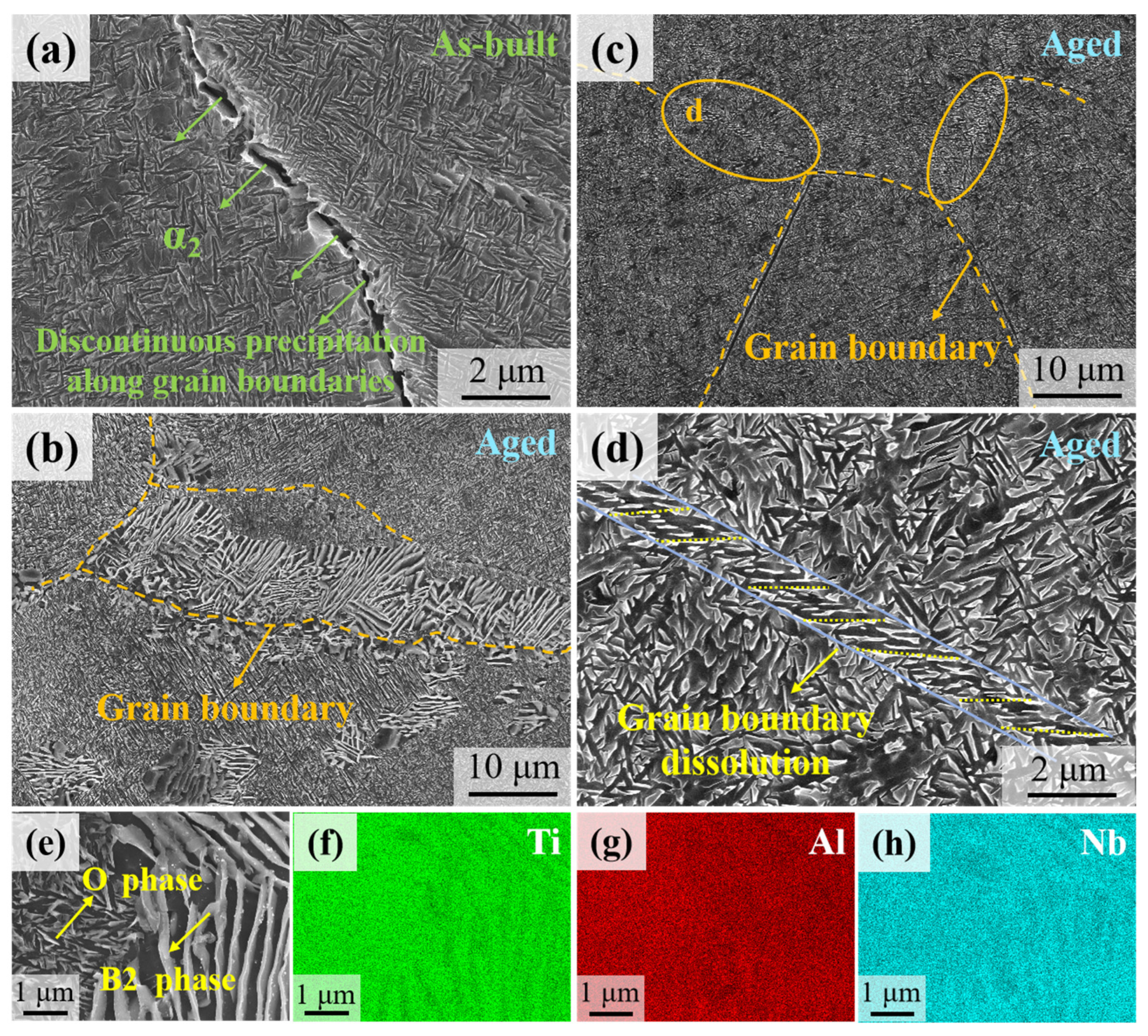
Figure 3 shows the microstructures around the grain boundaries of the as-built and aged samples. Figure 3a reveals discontinuous growth of the α2 phase at the grain boundaries in the as-built sample, likely induced by interfacial energy effects during the nucleation and growth of the α2 phase at the grain boundaries during the deposition process. Figure 3b displays the microstructure near the grain boundaries of the aged sample. After prolonged aging treatment, abnormally coarsened lath-shaped structures with lengths ranging from 5 to 15 μm are observed near the grain boundaries. The EDS elemental maps of a randomly selected abnormally coarsened lath structure region indicate that the lighter lath-shaped regions correspond to the recrystallized B2 phase, while the darker lath-shaped or spherical structures consist of a mixed microstructure of O and α2 phases, Figure 3e–h [51]. Such microstructure is induced by elemental enrichment at the grain boundaries during prolonged aging, which promotes abnormal growth of the lath structures. Figure 3c,d show partial “dissolution” of the grain boundaries in certain regions, where the grown lath-shaped structures exhibit specific angular relationships with the original grain boundaries. Prolonged aging reduces the stability of the grain boundaries, allowing solute atoms to diffuse from the grain boundaries into the grain interior, resulting in grain boundary dissolution.
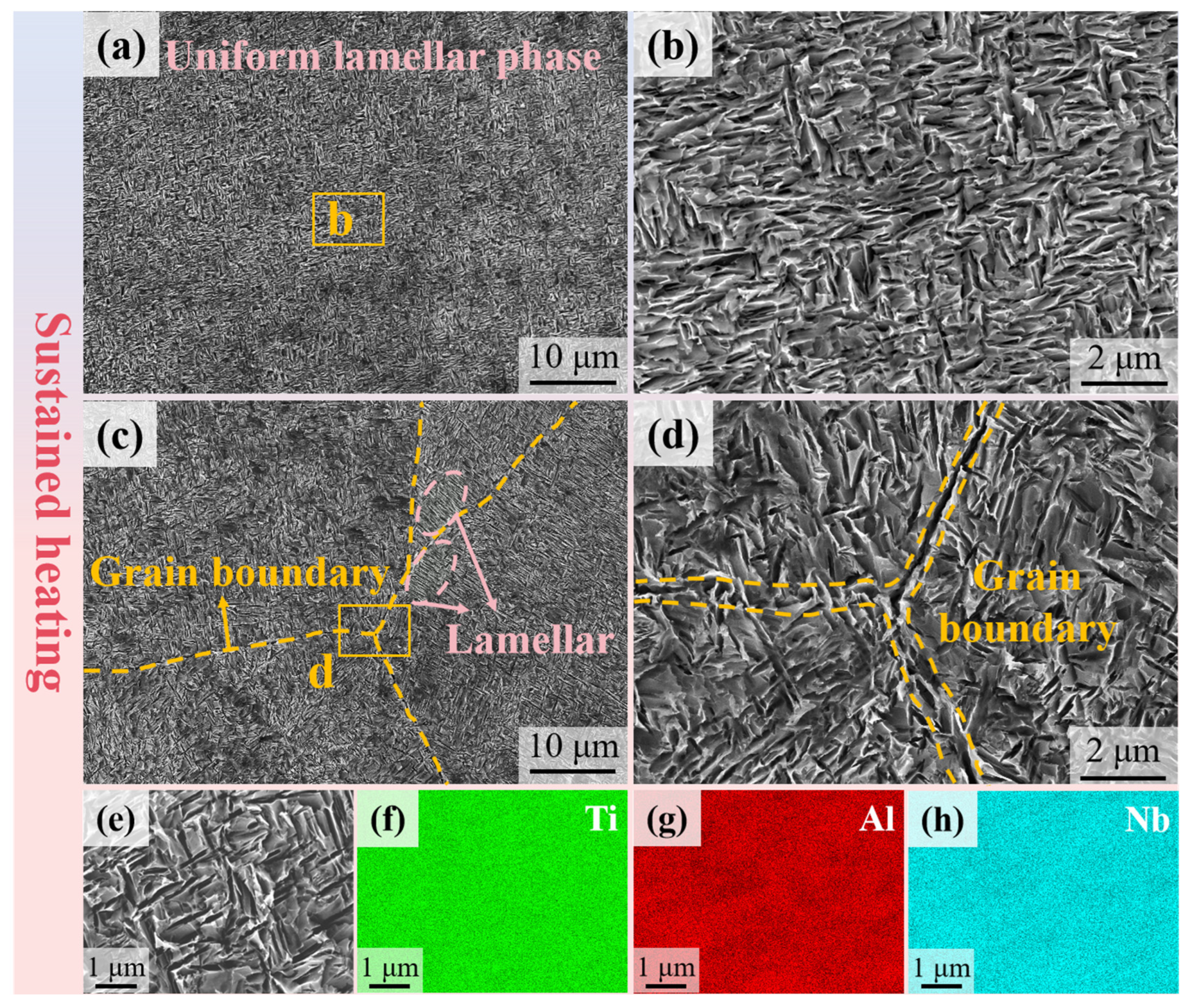
Figure 4 presents the microstructure features of the internal cyclically heated sample within grain interiors and at grain boundaries. In Figure 4a, uniformly distributed lath-shaped structures can be observed. Upon magnification (Figure 4b), these interwoven darker phases are identified as the O phase (Ti2AlNb phase). Figure 4c,d provide further details of the microstructure at triple junctions. Similarly to the aged sample, lath-shaped structures approximately perpendicular to the grain boundaries are observed on both sides of the boundaries. However, unlike the aged sample, these laths exhibit a specific orientation without abnormal growth (which is further confirmed by related mechanical properties). Magnified views of the triple junctions show no significant grain boundary ‘dissolution’, which was observed in the aged sample, but darker lath-shaped O phases growing along grain boundaries are clearly visible. SEM-EDS elemental maps of a randomly selected region in the internal cyclically heated sample (Figure 4e–h) reveal a homogeneous distribution of Ti, Al, and Nb elements without noticeable segregation. This further demonstrates that cyclic heating effectively homogenizes the microstructure, which is beneficial for the mechanical properties.
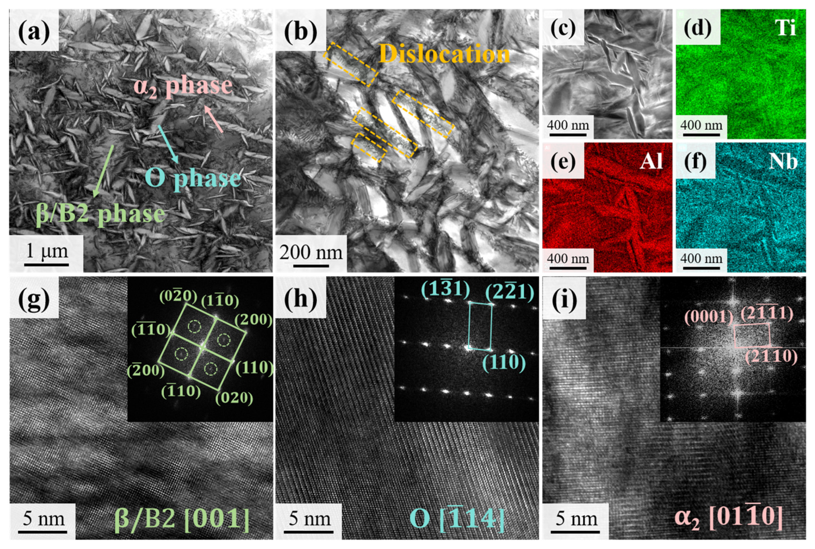
Figure 5 shows the TEM images of the precipitate distribution and substructure in the as-built sample. Within the grains, a large number of clustered lath-shaped precipitates and fine needle-like phases are observed, Figure 5a. Dislocation walls formed by aligned dislocations are visible at the interfaces between some lath-shaped precipitates and the matrix. A few dislocation walls cut through the lath structures, segmenting them Figure 5b. Magnification of the central region in Figure 5a and subsequent STEM-EDS analysis reveal that the lath-shaped features are Al-enriched and Nb-depleted. According to the literature [52], such Al-rich and Nb-depleted phases are as assigned to the O phase. The structures of different phases were further analyzed via HRTEM imaging. Figure 5g–i present high-resolution images and corresponding fast Fourier transform (FFT) patterns, which are further confirmed as the matrix β/B2 phase, O phase, and α2 phase [31].
Figure 6 presents TEM results of the aged sample. After prolonged aging treatment, the lath-shaped structures exhibited severe coarsening, consistent with the SEM observations described earlier (Figure 2f). Coarse lath structures remained interwoven with needle-like and ellipsoidal phases, as shown in Figure 6a. The region marked by the orange solid box was selected for high-resolution imaging of the lath-shaped structure. Fourier transform analysis confirmed that these laths were identified as the O phase. EDS elemental mapping further confirmed that these Al-rich and Nb-depleted lath-shaped structures are O phase, with the nanosized needle-like structures adjacent to them, Figure 6b–f. High-resolution imaging reveals clear B2/α2 interfaces, Figure 6h. Fourier transform analysis identified the bright needle-like structures (marked by orange solid circles) as α2 phase, while the darker matrix was confirmed as β/B2 phase, as shown in Figure 6g,i.
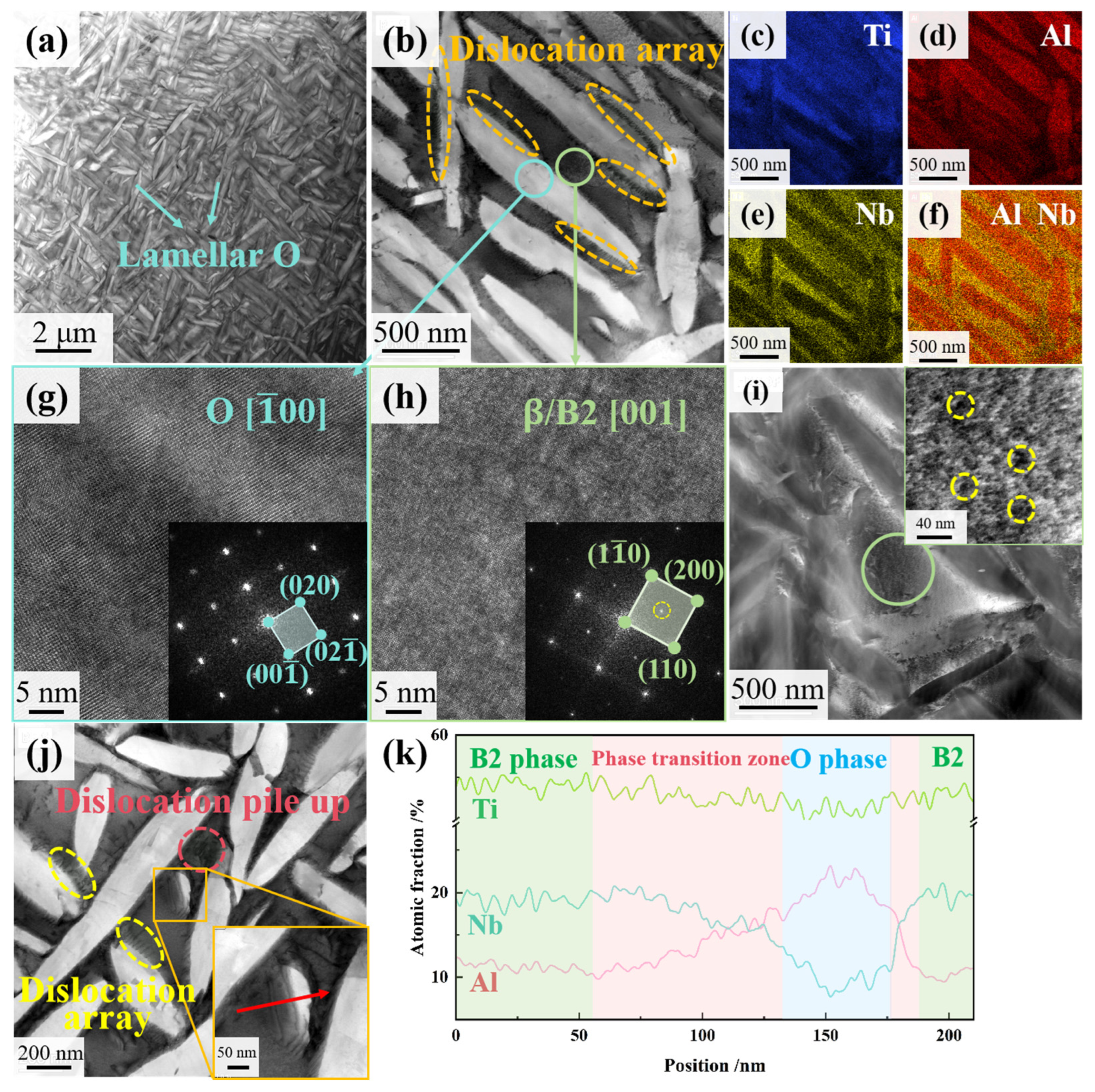
Figure 7a presents TEM analysis of the phase distribution in the internal cyclically heated sample. Unlike the as-built and aged samples, the lath-shaped structure in the internally cyclic heated sample exhibits a more uniform size and distribution, with no significant clustering or abnormal growth. As shown in Figure 7b, numerous orderly arranged dislocations are observed at the B2/O interfaces between the matrix and lath structures, which are absent in the as-built or aged samples. STEM-EDS analysis confirms that the lath structures remain Al-enriched and Nb-depleted, while Ti shows some enrichment in the matrix, Figure 7c–f. FFT identifies the lath-shaped precipitates as O phase, and the matrix structure as BCC phase, comprising both ordered B2 phase and disordered β phase, as shown in Figure 7g,h. Superlattice spots are observed at the 1/2 (200) positions (marked by bright yellow dashed circles in Figure 7h). Magnification of the matrix phase in Figure 7i reveals black nanoscale precipitates with diameters below 10 nm, indicating the formation of a disordered β-phase responsible for the superlattice diffraction spots [31]. In addition to the ordered dislocation arrays at phase interfaces, dislocation pile-ups are observed near some lath-shaped structures, Figure 7j. Elemental line scanning analysis across the transition zone between the matrix and needle-like O phase reveals the compositional differences between the BCC structure and O phase. In the two-phase transition region, Nb content decreases gradually while Al content increases, ultimately forming an Al-rich and Nb-depleted O phase. Study [53] indicates that the critical cooling rate of α2 phase precipitation is much lower than that of O phase, explaining the absence of α2 phase in this sample.
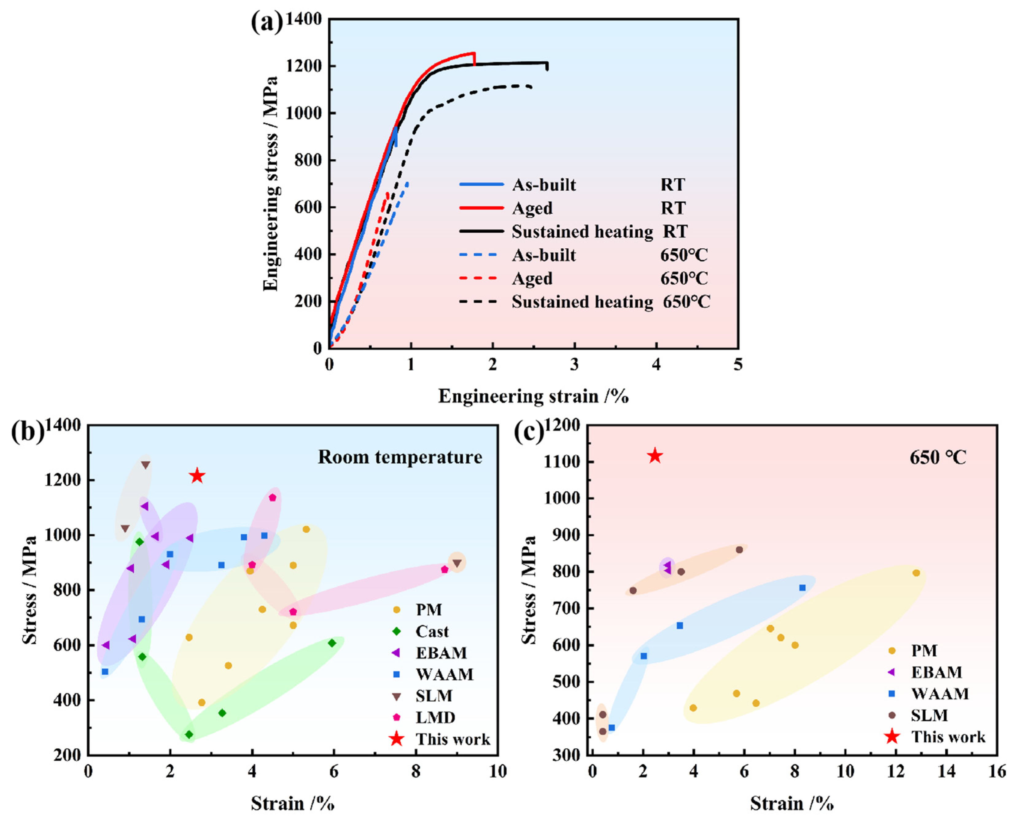
The mechanical properties of the as-built, aged, and internally cyclically heated Ti2AlNb alloy were evaluated at both room and elevated temperatures (650 °C), with the related engineering stress–strain curves in Figure 8a. The as-built sample exhibited a room-temperature ultimate tensile strength (UTS) of 938 MPa and a fracture elongation of 0.81%. The aged sample showed a room-temperature UTS of 1255 MPa and an elongation of 1.77%. In comparison, the internal cyclically heated sample achieved a room-temperature UTS of 1215 MPa with an elongation of 2.66%. Compared to the as-built sample, the aged and internally cyclically heated samples exhibit 33.8% and 29.5% higher room-temperature UTS and 118.5% and 228.4% higher elongation, respectively. Both aging treatment and internal cyclic heating can enhance the room-temperature tensile properties of the as-built Ti2AlNb alloy. Testing at 650 °C, the as-built sample exhibited a UTS of 702 MPa and an elongation of 0.95%. The aged sample showed a UTS of 658 MPa and an elongation of 0.71%. In contrast, the internal cyclically heated sample achieved the highest high-temperature UTS of 1116 MPa with the largest elongation of 2.47%. These represent 59% and 160% increases in UTS and elongation compared to the as-built sample (Results from multiple sets of parallel tests are provided in Table S1 and Figure S1).
Figure 8b,c compare the room-temperature and 650 °C tensile properties of the internal cyclically heated Ti2AlNb alloy with those of the conventionally prepared, additive-manufactured Ti2AlNb alloy reported in previous studies, respectively. The results indicate that the internally cyclically heated deposited Ti2AlNb alloy in this study exhibits superior performance to those fabricated by traditional powder metallurgy (PM) [54,55,56,57,58], casting [31,59,60], electron beam additive manufacturing (EBAM) [43,61,62], and wire-arc additive manufacturing (WAAM) [42,63,64,65] in both room-temperature and high-temperature mechanical properties. Compared to Ti2AlNb alloy produced by selective laser melting (SLM) [45,66,67] and other LMD [2,68], this study achieves a synergistic improvement in strength and ductility at room temperature. At 650 °C, the ultimate tensile strength significantly exceeds previously reported values while maintaining an elongation of 2.47%.
The SEM fractography of the room-temperature tensile specimens is analyzed in Figure 9. Figure 9a shows the overall fracture morphology of the as-built sample. Intergranular cracks are observed in the as-built sample, Figure 9d. Figure 9g reveals stepped fracture patterns and minor tear ridges in local regions, indicating transgranular fracture characteristics. Figure 9b shows the overall fractography of the aged sample. Figure 9e,h show numerous intergranular cracks, tear ridges, and typical river patterns consistent with a dominating cleavage fracture mode. Figure 9c shows the overall fractography of the internally cyclically heated sample. Fine dimples are observed on its intergranular fracture surface, Figure 9f, likely related to O-phase precipitation. The intergranular cracks in Figure 9f suggest deformation initiates at grain boundaries, implying that grain boundary strength governs the material’s strength. Furthermore, tear ridges and small dimples embedded within the grain boundary are observed in Figure 9i, exhibiting mixed intergranular and transgranular fracture behavior for the internally cyclically heated sample.
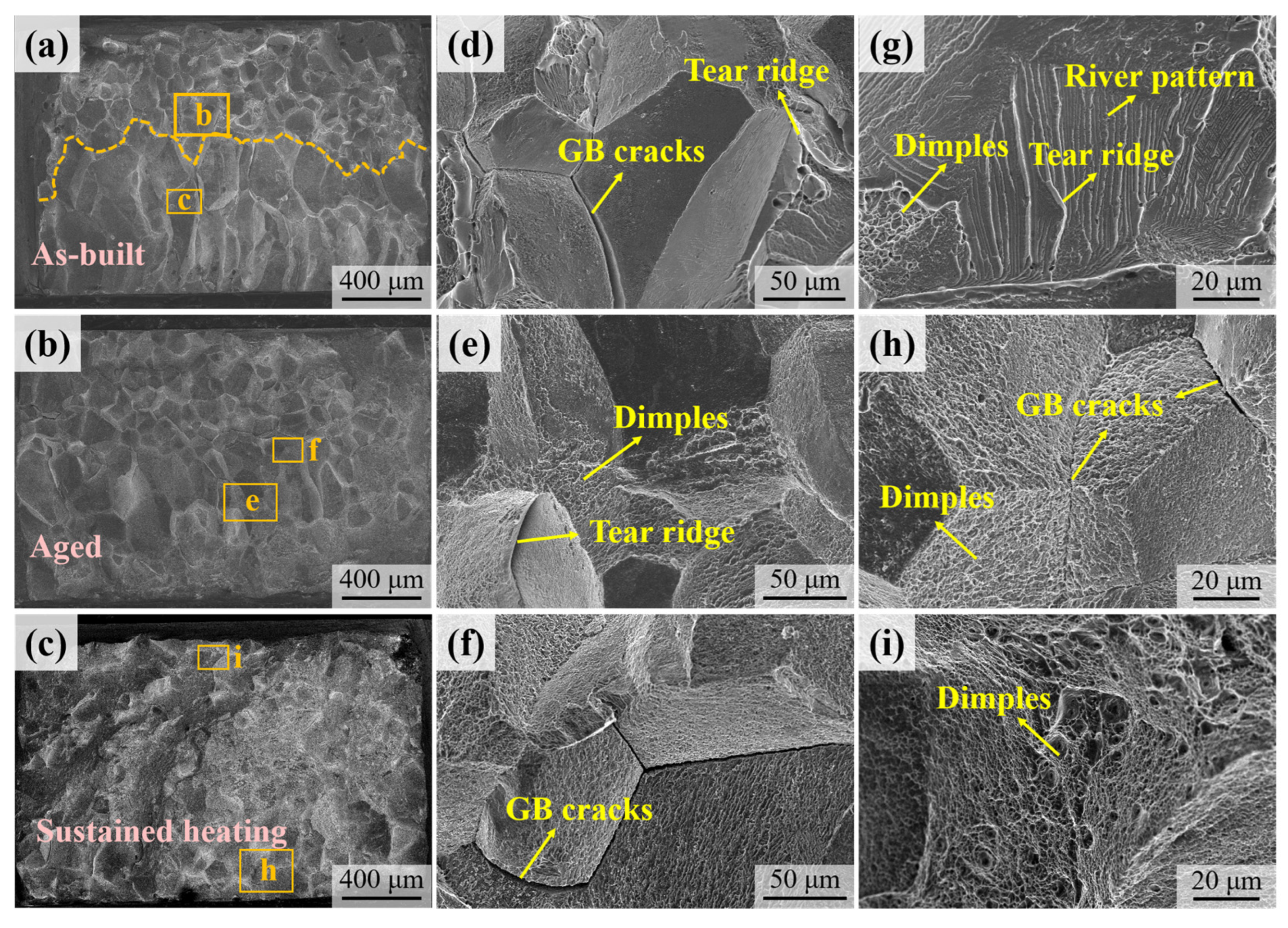
Figure 10 shows the fractography of the samples after high-temperature (650 °C) tensile testing. The fracture surface of the as-built sample in Figure 10a is divided into upper and lower regions with equiaxed and columnar grains, respectively. The equiaxed grain region (upper region) exhibits intergranular fracture characteristics, with partially smooth fracture surfaces indicating embrittlement of B2 grain boundaries, Figure 10d. Similar grain boundary embrittlement features in Ti2AlNb alloy at 750 °C were reported by Bin et al. [5]. Numerous intergranular cracks and tear ridges are observed in the upper region of the high-temperature tensile as-built sample, while its columnar grain region displays minor dimples and river patterns characteristic of cleavage fracture Figure 10g. Figure 10b,e,h reveal that the fracture surface of the aged sample still maintains equiaxed and columnar grain morphology. Although the number of dimples increases compared to the as-built condition, the fracture propagation remains predominantly intergranular. The fracture morphology of the internally cyclically heated sample in Figure 10c,f,i differ from both the as-built and aged samples. The fracture surface exhibits numerous dimples combined with intergranular fracture and grain boundary cracks regions, demonstrating a mixed intergranular and ductile fracture mode.
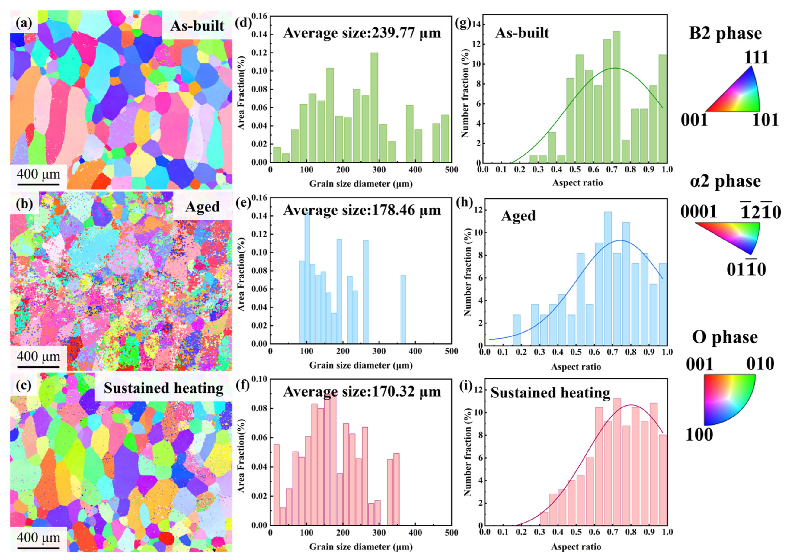
Figure 11 displays the EBSD inverse pole figure (IPF) maps, equivalent circle diameter (ECD) distributions, aspect ratio trends, and corresponding Gaussian fitting results along the build direction for the samples under different post-treatment conditions. The as-built sample exhibits coarse columnar grains (300–500 μm in length) aligned between molten pool trajectories, with equiaxed grains predominantly located near the molten pool boundaries. This is attributed to the high thermal gradients within the molten pool during the additive manufacturing process. When depositing a subsequent layer on the solidified layer, the high temperature of the new molten pool causes partial remelting of the previously solidified upper region, thereby disrupting columnar growth and promoting localized equiaxed grain formation [69], Figure 11a. As a result, the microstructure comprises coarse columnar grains in the molten pool cores and finer equiaxed grains along the molten pool boundaries, yielding an average grain size of ~240 μm, Figure 11d. Following prolonged aging at 750 °C, the microstructure transitions to shorter, wider near-equiaxed grains with fine recrystallized grains emerging, Figure 11b. The maximum ECD was constrained below 400 μm, and the average grain size was refined to ~178 μm (Figure 11e), confirming substantial microstructural refinement from aging treatment, Figure 2d.
The internal cyclically heated sample retained columnar grain characteristics in the molten pool interior, but its grain length was significantly smaller than that of the as-built sample, Figure 11c. Meanwhile, the number of equiaxed grains near the molten pool boundaries increased, with numerous fine equiaxed grains via recrystallization. Due to internal cyclic heating, the reduced interlayer thermal gradient effectively suppressed the preferred orientation growth of crystals along the thermal gradient and promoted homogeneous nucleation, driving grain morphology toward a near-equiaxed structure, Figure 11c. The low thermal gradient alleviated the constraint of directional heat flow on crystal growth, increased the nucleation rate, and suppressed directional grain coarsening, thereby promoting a more refined, isotropic, and homogeneous microstructure. The average grain size of these samples was ~170 μm, Figure 11f. Such microstructural refinement enhances mechanical properties, as finer and more equiaxed grains improve material strength through the Hall–Petch strengthening mechanism [70].
The aspect ratio serves as an indicator for characterizing grain morphology. Studies have shown that values closer to 1 correspond to a more equiaxed grain structure [71]. Figure 11g–i presents the frequency distribution histograms and Gaussian fitting trends of the aspect ratio of as-built, aged, and internally cyclically heated samples. In the as-built sample, grains with an aspect ratio exceeding 0.7 accounted for 45.3% of the total population, Figure 11g. This proportion increased to 47.3% in the prolonged aged sample (Figure 11h) and further rose to 58.7% in the internally cyclically heated sample, Figure 11i. Corresponding Gaussian fitting results confirmed this trend, with the distribution peak shifting clearly toward 1, indicating a significant transition in grain morphology. These results demonstrate that an internally cyclically heated sample facilitates the transition of the grains from columnar to equiaxed shapes.
The instantaneous high-energy heat input during the LMD process induces non-equilibrium solidification, resulting in an unstable phase formation regime prone to elemental segregation. As a post-processing technique, prolonged aging treatment enables precise control of the phase transformation process for microstructural regulation. After holding at 750 °C—near the B2/O-phase transformation temperature—for 48 h, a substantial portion of B2 phase transforms, Figure 6a, while the O phase grows sufficiently and coarsens, Figure 2f. Additionally, nanoscale α2 phase precipitated from the matrix, which may eliminate the non-equilibrium phases formed during deposition [72]. Due to the higher energy state at grain boundaries [73], these regions remain unstable, Al and Nb elements preferentially accumulate and segregate here, and the lath-shaped O phase preferentially nucleates and grows along these areas, resulting in extensive abnormally coarse lamellar structures, Figure 3b.
To further improve the post-processing, this study developed an internal cyclic heating technique. By combining high-temperature preheating of the deposition platform with optimized scanning strategies, this technique enables real-time regulation of the O-phase transformation process, promoting the homogeneous and interwoven distribution of lath-shaped O-phase precipitates throughout the matrix and achieving microstructural homogenization. As a critical strengthening phase in Ti2AlNb alloys, the O phase plays a vital role in governing both the strength and ductility of the material [74]. The as-built sample’s extremely high cooling rate left insufficient time for complete O-phase precipitation [53], resulting in a non-uniform O-phase microstructure with varied sizes and morphologies, Figure 2a. Prolonged aging promotes abnormal coarsening of the O phase, and the resulting coarse O-phase laths negatively impact high-temperature deformation performance, Figure 3b and Figure 6a [75]. After internal cyclic heating, the diffraction peak intensities of both the B2/β phase and the O-phase increase. SEM observations reveal that the lath-shaped structures undergo more homogeneous growth compared to the as-built condition (Figure 2a), avoiding the abnormal coarsening seen after aging, and exhibiting more uniform distribution within the matrix. TEM bright-field images show that in the as-built sample, lath and acicular phases are sparsely clustered, Figure 5a. After prolonged aging treatment, the lath-shaped structures coarsened and aligned uniformly, Figure 6a. In contrast, under internal cyclic heating, O-phase precipitates distribute uniformly, overlapping throughout the matrix, Figure 7a. The lath-shaped O phase exhibits no abnormal growth and shows consistent size distribution, Figure 7b.
Such microstructure changes are mainly attributed to the introduction of an internal heat source to the cyclic heating during deposition, which complements the inherently transient and unstable thermal input of the process. Consequently, elements undergo sufficient diffusion, and the system gains adequate time to approach equilibrium [76], thus promoting the full precipitation and growth of the O phase, crucial for enhancing mechanical properties. Furthermore, this cyclic heating reduces thermal gradients, suppressing the longitudinal growth of columnar grains and encouraging equiaxed grain formation, contributing to grain refinement, Figure 11c. Such thermal retention effect of cyclic heating notably decreases the cooling rate, reduces compositional segregation, and ensures microstructural homogeneity.
Therefore, the enhancement in overall performance after internal cyclic heating results from the synergistic interplay of multiple reinforcing mechanisms, grain refinement strengthening, precipitation strengthening, and dislocation strengthening. Compared to the as-built sample, the uniformly distributed lath-shaped O phase in the internally cyclically heated sample hinders dislocation motion. A large number of dislocations align in an orderly fashion along the phase boundaries between the O-phase laths and the B2 matrix. The accumulation of these dislocations contributes to strengthening [77], thereby enhancing the room-temperature strength. Additionally, the prevalence of nearly equiaxed grains imparts excellent isotropy, facilitating uniform plastic deformation during testing, mitigating stress concentration, and boosting ductility. The high-temperature tensile properties critically depend on phase boundary stability and grain boundary strengthening. Under the influence of the internal cyclical heating stage, recrystallization occurs within the system, leading to fine equiaxed grain formation, Figure 11c. Meanwhile, the reduced interlayer thermal gradient weakens columnar grain growth tendency, promoting equiaxed grain formation instead [78]. This increase in grain boundary area impedes dislocation motion—consistent with the Hall–Petch relationship—and serves as the primary diver of strength improvement. Furthermore, internal cyclic heating enhances microstructural stability at high temperatures. During high-temperature tensile testing, grain size and phase distribution remain unchanged (Figure 11f), ensuring consistent performance. Stabilized precipitates and uniformly coarsened phases feature high-temperature dissolution-resistant interfaces, contributing further to the strengthening.
Additionally, for the internal cyclic heating technique, the cooling rate is sufficiently reduced to facilitate the complete transformation of the B2 phase to the O phase. The sustained and stable thermal input promotes sufficient diffusion of elements such as Nb and Al, thereby significantly reducing elemental segregation. Cai et al. [79] investigated the effects of high-temperature thermal exposure (650–1050 °C) on elemental diffusion, second-phase precipitation, and microstructural homogeneity in welded Ti2AlNb joints. The results indicate that elevated temperatures mitigate segregation and enhance performance, providing experimental support for our results. After deposition, the sample is cooled alongside the cyclic heating stage (equivalent to furnace cooling), preventing the precipitation of detrimental phases and the formation of heterogeneous structures compared to rapid cooling.
This cyclic heating strategy effectively synergistically enhances both room-temperature and high-temperature properties in Ti2AlNb alloy, overcoming the limitations of conventional heat treatments that often fail to balance these competing demands. The internally cyclically heated sample delivers a room-temperature tensile strength of 1215 MPa with an elongation of 2.66%, and a 650 °C high-temperature strength of 1116 MPa, outperforming samples treated with conventional aging processes. Thus, the internal cyclic heating method obviates the need for time-consuming, complex conventional solution-aging post-treatments, providing an efficient, scalable pathway for lightweight aerospace component manufacturing.

4. Conclusions

This study developed an internally cyclically heated approach for laser melting-deposited Ti2AlNb alloy. Using a multiscale characterization technique and mechanical evaluations, we systematically studied the influence of internal cyclic heating on the microstructure and mechanical properties of Ti2AlNb alloy during LMD. This work also compared the results with traditional aging treatment, providing deeper insights into the relationships among in situ treatment, microstructure, and high-temperature performance. Based on the findings, the following conclusions are drawn:
  • The as-built alloy exhibits microstructural heterogeneity and unstable mechanical properties due to significant thermal gradients and high cooling rates during deposition, often leading to brittle fracture at elevated temperatures. After prolonged aging treatment at 750 °C for 48 h followed by air cooling, the microstructure exhibits notably refined grains and reduced inhomogeneity.
  • Prolonged aging treatment promotes sufficient growth and precipitation of the lath-shaped O phase. Simultaneously, it forms a network-like structure of “dual-scale lath-shaped O-phase” that balances resistance to dislocation motion and strengthening effects. This enhances the room-temperature strength of the Ti2AlNb alloy from 938 MPa to 1255 MPa, while maintaining an elongation of 1.77%. However, the abnormally coarsened lath structures at grain boundaries are highly unstable at elevated temperatures, prone to decomposition and fracture, compromising high-temperature strength.
  • By providing controlled and sustained thermal input during deposition, this internal cyclic heating technique offers excellent thermal management, significantly reducing cooling rates, promoting grain morphology transition from columnar to equiaxed, and refining grain structure. It also minimizes elemental segregation, facilitates homogeneous distribution of equiaxed grains, and enables the uniform precipitation of a high density of fine, dispersed O-phase precipitates in the matrix.
  • Such microstructure of the internally cyclically heated sample contributes to the strengthening mechanism of grain refinement and precipitate dispersion, thereby achieving simultaneous optimization of both room-temperature and high-temperature performance. Specifically, it delivers a room-temperature strength of 1215 MPa with an elongation of 2.66%, and a 650 °C high-temperature strength of 1116 MPa with an elongation of 2.47%, providing a novel processing approach to balance performance and efficiency in Ti2AlNb alloys.

Supplementary Materials

The following supporting information can be downloaded at: https://www.mdpi.com/article/10.3390/cryst15110910/s1, Figure S1: Room temperature and high temperature tensile properties of the as-built, the aged, and the internal cyclically heated sample at 650 °C; Table S1: Room temperature and high temperature tensile properties of the as-built, the aged, and the internal cyclically heated sample at 650 °C.

Author Contributions

Conceptualization, L.L.; methodology, C.Z., Y.L. and Z.H.; formal analysis, L.L.; investigation, C.Z.; resources, Y.L. and Y.P.; data curation, C.Z.; writing—original draft preparation, C.Z. and Q.G.; writing—review and editing, C.Z. and Q.G.; visualization, C.Z.; funding acquisition, Q.G. All authors have read and agreed to the published version of the manuscript.

Funding

This research was funded by the Excellent Young Scientists Fund Program of the National Natural Science Foundation of China (Overseas).

Data Availability Statement

The original contributions presented in this study are included in the article/Supplementary Materials. Further inquiries can be directed to the corresponding authors.

Conflicts of Interest

The authors declare no conflict of interest.

References

  1. Zhou, Y.H.; Li, W.P.; Zhang, L.; Zhou, S.Y.; Jia, X.; Wang, D.W.; Yan, M. Selective laser melting of Ti–22Al–25Nb intermetallic: Significant effects of hatch distance on microstructural features and mechanical properties. J. Mater. Process. Technol. 2020, 276, 116398. [Google Scholar] [CrossRef]
  2. Zhang, S.; Xi, M.; Sun, X.; Liu, Y.; Zheng, C.; Bai, D.; Wang, S. Significant effect of press down volume on microstructural evolution and mechanical properties of Ti2AlNb intermetallic alloy prepared by point-forging and laser-deposition. Mater. Sci. Eng. A 2024, 907, 146672. [Google Scholar] [CrossRef]
  3. He, Y.-S.; Hu, R.; Luo, W.-Z.; He, T.; Liu, X.-H. Oxidation behavior of a novel multi-element alloyed Ti2AlNb-based alloy in temperature range of 650–850 °C. Rare Met. 2018, 37, 838–845. [Google Scholar] [CrossRef]
  4. Illarionov, A.G.; Stepanov, S.I.; Naschetnikova, I.A.; Popov, A.A.; Soundappan, P.; Thulasi Raman, K.H.; Suwas, S. A Review—Additive Manufacturing of Intermetallic Alloys Based on Orthorhombic Titanium Aluminide Ti2AlNb. Materials 2023, 16, 991. [Google Scholar] [CrossRef] [PubMed]
  5. Shao, B.; Tang, W.; Guo, S.; Zong, Y.; Shan, D.; Guo, B. Investigation of the O phase in the Ti–22Al–25Nb alloy during deformation at elevated temperatures: Plastic deformation mechanism and effect on B2 grain boundary embrittlement. Acta Mater. 2023, 242, 118467. [Google Scholar] [CrossRef]
  6. Chen, Z.; Wan, J.; Li, J.; Li, J.; Wang, J. Uncovering the different roles of lack-of-fusion and keyhole defects on the tensile behavior of additively manufactured Ti-6Al-4V alloy. Addit. Manuf. 2025, 110, 104944. [Google Scholar] [CrossRef]
  7. Wang, J.; Li, Z.; Wu, Q.; Xu, T. The Creep Properties and Mechanism of Ti-6Al-4V with Ultra-Low β Contents Fabricated by Wire Arc Additive Manufacturing. Addit. Manuf. Front. 2025, 200246. [Google Scholar] [CrossRef]
  8. Lu, F.; Ma, Q.; Liu, E.; Wei, R.; Bai, J.; Gao, Q.; Qi, J. Advancements in understanding the microstructure and properties of additive manufacturing Ti-6Al-4V alloy: A comprehensive review. J. Alloys Compd. 2025, 1027, 180543. [Google Scholar] [CrossRef]
  9. Mohanty, I.; Kar, S.K. A comprehensive review of aspects of columnar to equiaxed transition, phase stability, and properties in novel Ti-alloys developed by additive manufacturing. J. Alloys Compd. 2025, 1038, 182642. [Google Scholar] [CrossRef]
  10. Zhou, W.; Shen, C.; Wang, L.; Li, Y.; Zhang, T.; Xin, J.; Ding, Y.; Zhang, D.; Zhang, Y.; Li, F.; et al. High-temperature tensile and fatigue properties of Ti-48Al-2Cr-2Nb alloy additively manufactured via twin-wire directed energy deposition-arc. Intermetallics 2025, 184, 108833. [Google Scholar] [CrossRef]
  11. Nie, Z.; Guo, Q.; Chai, J.; Chen, Z.; Li, J.; Dong, H.; Ding, R.; Liu, C.; Ma, Z.; Tian, X.; et al. Initial γ’ phase formation mechanism in a GH4099 precipitation strengthened nickel-based superalloy. Scr. Mater. 2025, 264, 116702. [Google Scholar] [CrossRef]
  12. Hao, Z.; He, Z.; Nie, Z.; Li, J.; Ma, Z.; Guo, Q. Effects of residual Laves phase on microstructural evolution and mechanical properties of wire arc additive manufactured GH4169 Ni-based superalloy. Mater. Sci. Eng. A 2024, 914, 147175. [Google Scholar] [CrossRef]
  13. Nie, Z.; Guo, Q.; Zhao, Y.; Ma, Z.; Liu, Y. Temperature dependence tensile behaviors of additively manufactured GH4099 Ni-based superalloy. Mater. Sci. Eng. A 2024, 899, 146464. [Google Scholar] [CrossRef]
  14. Silva, C.C.; Silva, R.S.; Miná, É.M.; Motta, M.F.; Miranda, H.C.; Dalpiaz, G.; Marinho, R.R.; Paes, M.T.P.; da Silva, A.K.; Wossack, I.; et al. Heterogeneously structured Ni-based alloy obtained by wire-arc additive manufacturing overcomes the strength-ductility trade-off. J. Mater. Sci. Technol. 2026, 254, 168–179. [Google Scholar] [CrossRef]
  15. Özsoy, A.; Gaudez, S.; Hearn, W.A.; Baganis, A.; Hegedüs, Z.; Chen, Y.; Rack, A.; Logé, R.E.; Van Petegem, S. Phase-separation-driven cracking in additive manufacturing of Ni-Cu alloy systems. Addit. Manuf. 2025, 110, 104950. [Google Scholar] [CrossRef]
  16. Jiang, X.; Luo, S.; Chen, M.; Nagaumi, H.; Wu, Y.; Cao, M.; Wang, X.; Hu, Z. In-situ precipitation kinetics and property gradients of a novel Al-Si-Cu-Mg alloy fabricated via CMT wire-arc additive manufacturing. J. Alloys Compd. 2025, 1040, 183430. [Google Scholar] [CrossRef]
  17. Zhang, W.; Yi, H.; He, H.; Cao, H. Content effects of in-situ synthesis TiC for grain refinement, porosity suppression and performance enhancement in wire arc additive manufactured Al-Cu alloy. J. Mater. Process. Technol. 2025, 340, 118875. [Google Scholar] [CrossRef]
  18. Zhao, R.; Li, L.; Liu, C.; Wang, Z.; Guo, Q. Effects of intermediate layer on interfacial microstructure and related mechanical properties of Inconel 625 coating on a Cu-Cr-Zr substrate by laser direct energy deposition. Mater. Charact. 2025, 226, 115227. [Google Scholar] [CrossRef]
  19. Maharjan, N.; Boschen, M.; Meure, S.; Ang, A. Depositing plasma sprayed NiCoCrAlY coating on additively manufactured Inconel 718 surfaces: Is grit blasting always necessary? Mater. Lett. 2025, 387, 138238. [Google Scholar] [CrossRef]
  20. Zhou, X.; Yu, Y.; Wang, X. Preparation of WC coatings via additive manufacturing technology: Microstructure, friction properties, and finite element simulation. Mater. Lett. 2025, 384, 138072. [Google Scholar] [CrossRef]
  21. Anand, K.S.; Rajkumar, V.; Nagesha, B.K.; Amit, K.T.; Sanjay, B.; Suresh, T.N. Single crystal metal deposition using laser additive manufacturing technology for repair of aero-engine components. Mater. Today Proc. 2021, 45, 5395–5399. [Google Scholar] [CrossRef]
  22. Li, Y.; Wu, J.; Li, M.; Xu, W.; Ye, R.; Wang, Z. Improved Inconel 718 superalloy repaired performance on 304 stainless steel shafts via recrystallization and Laves phase suppression in hybrid additive-subtractive manufacturing. J. Mater. Res. Technol. 2025, 37, 3289–3302. [Google Scholar] [CrossRef]
  23. Javidrad, H.; Koc, B. Additively manufacturing of functionally graded multi-material parts using directed energy deposition. CIRP J. Manuf. Sci. Technol. 2025, 61, 588–600. [Google Scholar] [CrossRef]
  24. Jeong, T.-W.; Cho, Y.T.; Lee, C.-M.; Kim, D.-H. Effects of ultrasonic treatment on mechanical properties and microstructure of stainless steel 308L and Inconel 718 functionally graded materials fabricated via double-wire arc additive manufacturing. Mater. Sci. Eng. A 2024, 896, 146298. [Google Scholar] [CrossRef]
  25. Ren, J.; Zhang, Y.; Zhao, D.; Chen, Y.; Guan, S.; Liu, Y.; Liu, L.; Peng, S.; Kong, F.; Poplawsky, J.D.; et al. Strong yet ductile nanolamellar high-entropy alloys by additive manufacturing. Nature 2022, 608, 62–68. [Google Scholar] [CrossRef] [PubMed]
  26. Svetlizky, D.; Das, M.; Zheng, B.; Vyatskikh, A.L.; Bose, S.; Bandyopadhyay, A.; Schoenung, J.M.; Lavernia, E.J.; Eliaz, N. Directed energy deposition (DED) additive manufacturing: Physical characteristics, defects, challenges and applications. Mater. Today 2021, 49, 271–295. [Google Scholar] [CrossRef]
  27. Lu, Y.; Wu, X.; Fu, Z.; Yang, Q.; Zhang, Y.; Liu, Q.; Li, T.; Tian, Y.; Tan, H.; Li, Z.; et al. Ductile and ultrahigh-strength eutectic high-entropy alloys by large-volume 3D printing. J. Mater. Sci. Technol. 2022, 126, 15–21. [Google Scholar] [CrossRef]
  28. Li, Y.; Yang, Y.; Xie, J.; Chen, L.; Zhang, X. Effect of cooling rate on microstructure and mechanical properties of AlMo0.5NbTa0.5TiZr refractory high-entropy alloy prepared by laser metal deposition. Mater. Sci. Eng. A 2025, 942, 148734. [Google Scholar] [CrossRef]
  29. Liu, Z.; Qin, Z.-X.; Liu, F.; Lu, X.; Wang, H.-M. The microstructure and mechanical behaviors of the Ti–6.5Al–3.5Mo–1.5Zr–0.3Si alloy produced by laser melting deposition. Mater. Charact. 2014, 97, 132–139. [Google Scholar] [CrossRef]
  30. Zhu, Y.; Tian, X.; Li, J.; Wang, H. The anisotropy of laser melting deposition additive manufacturing Ti–6.5Al–3.5Mo–1.5Zr–0.3Si titanium alloy. Mater. Des. 2015, 67, 538–542. [Google Scholar] [CrossRef]
  31. Yang, L.; Bu, Z.; Li, J. Microstructure and mechanical properties of as-cast Ti2AlNb alloys. Mater. Des. 2025, 254, 114138. [Google Scholar] [CrossRef]
  32. Ma, H.; Zeng, W.; Kou, Y.; Zhang, P.; Zhang, F.; Liang, X. Formation mechanism of Cube texture components ({001}<100>) associated with dynamic recrystallization during compression in the single BCC phase region of Ti-22Al-25Nb alloy. J. Alloys Compd. 2023, 966, 171563. [Google Scholar] [CrossRef]
  33. Zhou, M.; Bu, Z.; Zhou, Y.; Wang, J.; Zhu, L.; Huang, X.; Li, J. The effect of primary and secondary O phase on the mechanical properties and deformation behavior of Ti2AlNb alloy. J. Alloys Compd. 2025, 1032, 181160. [Google Scholar] [CrossRef]
  34. Shao, B.; Wan, S.; Xu, W.; Shan, D.; Guo, B.; Zong, Y. Formation mechanism of an α2 phase-rich layer on the surface of Ti-22Al-25Nb alloy. Mater. Charact. 2018, 145, 205–209. [Google Scholar] [CrossRef]
  35. Jiang, J.; Li, M.; Wang, Y.; Yang, L.; Gan, Z.; Jia, Q.; Hu, J.; Zhang, Y.; Zhang, X.; Yang, R. Evolution of the O phase in SiCf/Ti2AlNb composites fabricated by hot isostatic pressing. Mater. Charact. 2025, 226, 115218. [Google Scholar] [CrossRef]
  36. Shi, G.; Du, Z.; Chen, Y.; Zhu, B.; Liu, Y.; Zhang, Y. Effect of heat treatment on the microstructure and mechanical properties of Y2O3/Ti-22Al-25Nb composites. Mater. Sci. Eng. A 2025, 944, 148914. [Google Scholar] [CrossRef]
  37. Shi, G.; Chen, Y.; Du, Z.; Zhu, B.; Liu, Y.; Zhang, Y. Simultaneously improves the strength and ductility of the Y2O3/Ti-22Al-25Nb composite through multiple forging. J. Alloys Compd. 2025, 1036, 182066. [Google Scholar] [CrossRef]
  38. Zhang, K.; Lei, Z.; Ni, L.; Zhou, H.; Chen, Y. Improvement in microstructure and high-temperature brittleness of laser-welded Ti-22Al-25Nb joints with the addition of TiB2 powder. J. Mater. Process. Technol. 2021, 288, 116848. [Google Scholar] [CrossRef]
  39. Li, Y.; Chen, G.; Pang, G.; Fu, X.; Zhou, W. Effect of nano-Al2O3 addition on microstructure and mechanical properties of Ti2AlNb-based composites prepared by powder metallurgy. J. Alloys Compd. 2023, 968, 172268. [Google Scholar] [CrossRef]
  40. Polozov, I.; Sufiiarov, V.; Starikov, K.; Popovich, A. In situ synthesized Ti2AlNb-based composites produced by selective laser melting by addition of SiC-whiskers. Mater. Lett. 2021, 297, 129956. [Google Scholar] [CrossRef]
  41. Boehlert, C.J. Part III. The tensile behavior of Ti-Al-Nb O+Bcc orthorhombic alloys. Metall. Mater. Trans. A 2001, 32, 1977–1988. [Google Scholar] [CrossRef]
  42. Zhang, H.; Zai, L.; Wang, Y.; Xue, X. Insight into microstructural evolution and mechanical property correlations of Ti2AlNb-based alloy fabricated through wire arc additive manufacturing. Mater. Sci. Eng. A 2025, 938, 148477. [Google Scholar] [CrossRef]
  43. Li, Z.; Chang, B.; Zhang, D.; Zhang, H.; Liang, Z.; Wang, L.; Liu, C.; Du, D. Effect of post-heat treatment on Ti2AlNb-based alloy fabricated by twin-wire alternating dual-electron beam additive manufacturing technology. J. Mater. Sci. Technol. 2023, 157, 130–143. [Google Scholar] [CrossRef]
  44. Man, J.; Huang, L.; He, J.; Yang, H.; Lin, X. Effect of heat treatment on microstructure and properties of Ti2AlNb alloy formed by selective laser melting. J. Mater. Res. Technol. 2024, 33, 2549–2559. [Google Scholar] [CrossRef]
  45. Yang, X.; Zhang, B.; Bai, Q.; Xie, G. Correlation of microstructure and mechanical properties of Ti2AlNb manufactured by SLM and heat treatment. Intermetallics 2021, 139, 107367. [Google Scholar] [CrossRef]
  46. Chen, X.; Weidong, Z.; Wei, W.; Xiaobo, L.; Jianwei, Z. Coarsening behavior of lamellar orthorhombic phase and its effect on tensile properties for the Ti–22Al–25Nb alloy. Mater. Sci. Eng. A 2014, 611, 320–325. [Google Scholar] [CrossRef]
  47. Zhu, Y.; Wang, F.; Jia, S.; Zou, J.; Luo, Y.; Niu, Y.; Yang, X.; Wang, X.; Wang, J. Process-structure relationship and microstructure evolution of Ti–22Al–25Nb alloy under heat treatment. Mater. Chem. Phys. 2025, 343, 131006. [Google Scholar] [CrossRef]
  48. Shang, Z.; Niu, H.; Wang, A.; Lei, T.; Liu, G.; Zhong, L. Effects of solid solution and aging treatment on the microstructure evolution of Ti2AlNb alloy. J. Mater. Res. Technol. 2024, 30, 1095–1104. [Google Scholar] [CrossRef]
  49. Wang, L.; Zhang, Y.; Hua, X.; Shen, C.; Li, F.; Huang, Y.; Ding, Y.; Zhang, P.; Lu, Q.; Zhang, T.; et al. Twin-wire plasma arc additive manufacturing of the Ti–45Al titanium aluminide: Processing, microstructures and mechanical properties. Intermetallics 2021, 136, 107277. [Google Scholar] [CrossRef]
  50. Mao, Y.; Li, S.; Zhang, J.; Peng, J.; Zou, D.; Zhong, Z. Microstructure and tensile properties of orthorhombic Ti–Al–Nb–Ta alloys. Intermetallics 2000, 8, 659–662. [Google Scholar] [CrossRef]
  51. Zhang, Y.; Cai, Q.; Liu, Y. Formation of diverse B2+O structure and hardness of Mo-modified Ti-22Al-25Nb alloys upon cooling. Vacuum 2019, 165, 199–206. [Google Scholar] [CrossRef]
  52. Ayadh, W.; Denand, B.; Halkoum, A.; Boulet, P.; Sennour, M.; Delfosse, J.; Sallot, P.; Esin, V.A. Effect of prior α2 phase on precipitation kinetics of O-phase in advanced Ti2AlNb alloy. Acta Mater. 2023, 252, 118930. [Google Scholar] [CrossRef]
  53. Bu, Z.Q.; Zhang, Y.G.; Yang, L.; Kang, J.M.; Li, J.F. Effect of cooling rate on phase transformation in Ti2AlNb alloy. J. Alloys Compd. 2022, 893, 162364. [Google Scholar] [CrossRef]
  54. Yang, J.L.; Wang, G.F.; Zhang, W.C.; Chen, W.Z.; Jiao, X.Y.; Zhang, K.F. Microstructure evolution and mechanical properties of P/M Ti-22Al-25Nb alloy during hot extrusion. Mater. Sci. Eng. A 2017, 699, 210–216. [Google Scholar] [CrossRef]
  55. Wang, G.; Yang, J.; Jiao, X. Microstructure and mechanical properties of Ti–22Al–25Nb alloy fabricated by elemental powder metallurgy. Mater. Sci. Eng. A 2016, 654, 69–76. [Google Scholar] [CrossRef]
  56. Jia, J.; Zhang, K.; Jiang, S. Microstructure and mechanical properties of Ti–22Al–25Nb alloy fabricated by vacuum hot pressing sintering. Mater. Sci. Eng. A 2014, 616, 93–98. [Google Scholar] [CrossRef]
  57. Jia, J.; Liu, W.; Xu, Y.; Lu, C.; Liu, H.; Gu, Y.; Luo, J. Microstructure evolution, B2 grain growth kinetics and fracture behaviour of a powder metallurgy Ti-22Al-25Nb alloy fabricated by spark plasma sintering. Mater. Sci. Eng. A 2018, 730, 106–118. [Google Scholar] [CrossRef]
  58. Xiong, B.; Liu, K.; Wang, Z.; Peng, F. Phase Transformation and Tensile Behavior of Ti-22Al-25Nb Alloys with Bimodal Size Lamellar O-Phase Precipitates. J. Mater. Eng. Perform. 2021, 30, 8598–8605. [Google Scholar] [CrossRef]
  59. Chen, R.; Wang, Q.; Zhou, Z.; Su, Y.; Guo, J.; Ding, H.; Fu, H. Microstructure, tensile properties and creep behavior of high-Al TiAlNb alloy using electromagnetic cold crucible continuous casting. J. Alloys Compd. 2019, 801, 166–174. [Google Scholar] [CrossRef]
  60. Huang, Y.; Liu, Y.; Zhang, Y.; Liang, H. Thermal stability and mechanical properties of Ti–22Al–25Nb alloy with different initial microstructures. J. Alloys Compd. 2020, 842, 155794. [Google Scholar] [CrossRef]
  61. Li, Z.; Cui, Y.; Wang, L.; Zhang, H.; Liang, Z.; Liu, C.; Du, D. An investigation into Ti-22Al-25Nb in-situ fabricated by electron beam freeform fabrication with an innovative twin-wire parallel feeding method. Addit. Manuf. 2022, 50, 102552. [Google Scholar] [CrossRef]
  62. Chen, Q.; Xu, L.; Zhang, Y.; Zhao, L.; Hao, K.; Ren, W.; Han, Y. Additive manufacturing Ti-22Al-25 Nb alloy with excellent high temperature tensile properties by electron beam powder bed fusion. Addit. Manuf. 2024, 86, 104236. [Google Scholar] [CrossRef]
  63. Li, Z.; Cui, Y.; Yu, Z.; Liu, C. In-situ fabrication of Ti2AlNb-based alloy through double-wire arc additive manufacturing. J. Alloys Compd. 2021, 876, 160021. [Google Scholar] [CrossRef]
  64. Fu, R.; Yu, Z.; Wu, Q.; Liu, C. Microstructure evolution and property strengthening of Ti2AlNb alloys prepared by multi-wire arc-directed energy deposition. J. Mater. Process. Technol. 2024, 329, 118460. [Google Scholar] [CrossRef]
  65. Yu, Z.; Li, Z.; Guo, Y.; Fu, R.; Xu, T.; Liu, C. Homogenizing the composition of in-situ fabricated Ti2AlNb-based alloy via manipulating the droplet transfer mode of twin-wire arc additive manufacturing. J. Alloys Compd. 2022, 923, 165992. [Google Scholar] [CrossRef]
  66. Zhou, Y.H.; Wang, D.W.; Song, L.J.; Mukhtar, A.; Huang, D.N.; Yang, C.; Yan, M. Effect of heat treatments on the microstructure and mechanical properties of Ti2AlNb intermetallic fabricated by selective laser melting. Mater. Sci. Eng. A 2021, 817, 141352. [Google Scholar] [CrossRef]
  67. Polozov, I.; Starikov, K.; Popovich, A.; Sufiiarov, V. Mitigating Inhomogeneity and Tailoring the Microstructure of Selective Laser Melted Titanium Orthorhombic Alloy by Heat Treatment, Hot Isostatic Pressing, and Multiple Laser Exposures. Materials 2021, 14, 4946. [Google Scholar] [CrossRef]
  68. Tang, Y.J.; Zhang, Y.Z.; Liu, Y.T. Numerical and experimental investigation of laser additive manufactured Ti2AlNb-based alloy. J. Alloys Compd. 2017, 727, 196–204. [Google Scholar] [CrossRef]
  69. Li, L.; Zhang, C.; Liu, C.; Niu, S.; Zhao, R.; Li, C.; Ma, Z.; Guo, Q.; Liu, Y. Improved strength of commercial Ti-based metallic powder modified AlSi10Mg alloy prepared by laser directed energy deposition without sacrificing ductility. Mater. Sci. Eng. A 2025, 945, 148974. [Google Scholar] [CrossRef]
  70. Xu, G.; Zhao, X.; Xia, W.; Yue, Q.; Zheng, Z.; Gu, Y.; Zhang, Z. A review on microstructure design, processing, and strengthening mechanism of high-strength titanium alloys. Prog. Nat. Sci. Mater. Int. 2025, 35, 258–277. [Google Scholar] [CrossRef]
  71. Liu, X.W.; Yao, J.Q.; Ma, X.N.; Wang, Y.S.; Gao, N.; Shi, Y.; Fan, Z.T.; Du, H. Columnar-to-equiaxed transition and grain refinement by solute interaction effects. Mater. Charact. 2023, 205, 113288. [Google Scholar] [CrossRef]
  72. Hou, S.; Feng, J.; Chen, S.; Zhang, F.; Li, D. Effects of Zn Contents on Microstructure and Mechanical Properties of Semisolid Rheo-Diecasting Al-xZn-2Mg-1.5Cu Alloys. Materials 2022, 15, 2873. [Google Scholar] [CrossRef] [PubMed]
  73. Mclean, D.; Maradudin, A. Grain Boundaries in Metals. Wear 1959, 2, 240. [Google Scholar] [CrossRef]
  74. Li, C.; Lu, S.; Divinski, S.; Vitos, L. Theoretical and experimental grain boundary energies in body-centered cubic metals. Acta Mater. 2023, 255, 119074. [Google Scholar] [CrossRef]
  75. Zhou, M.; Li, J.; Zhang, K.; Xiong, J.; Li, J.; Du, Y. Precipitation behavior and strengthening mechanism of the interfacial nano-O phase of Ti2AlNb diffusion welded joints with high-entropy interlayer during aging process. Mater. Charact. 2025, 220, 114704. [Google Scholar] [CrossRef]
  76. Song, C.; Wu, D.; Di, T.; Xu, G.; Zhang, Z.; Wang, D.; Niu, F.; Ma, G.; Liu, L. Intermetallic phases transition mechanism of the interface of Ti6Al4V-Inconel718 graded material by laser additive manufacturing. Mater. Charact. 2024, 215, 114183. [Google Scholar] [CrossRef]
  77. Zhang, P.; Zeng, W.; Jia, R.; Kou, Y.; Xu, J.; Liang, X.; Zhao, Y. Tensile behavior and deformation mechanism for Ti–22Al–25Nb alloy with lamellar O microstructures. Mater. Sci. Eng. A 2021, 803, 140492. [Google Scholar] [CrossRef]
  78. Zheng, Y.; Zeng, W.; Li, D.; Zhao, Q.; Liang, X.; Zhang, J.; Ma, X. Fracture toughness of the bimodal size lamellar O phase microstructures in Ti-22Al-25Nb (at.%) orthorhombic alloy. J. Alloys Compd. 2017, 709, 511–518. [Google Scholar] [CrossRef]
  79. Cai, H.; Ma, Z.; Zhang, J.; Qi, L.; Hu, J.; Zhou, J. Different Heat-Exposure Temperatures on the Microstructure and Properties of Dissimilar GH4169/IC10 Superalloy Vacuum Electron Beam Welded Joint. Metals 2024, 14, 348. [Google Scholar] [CrossRef]
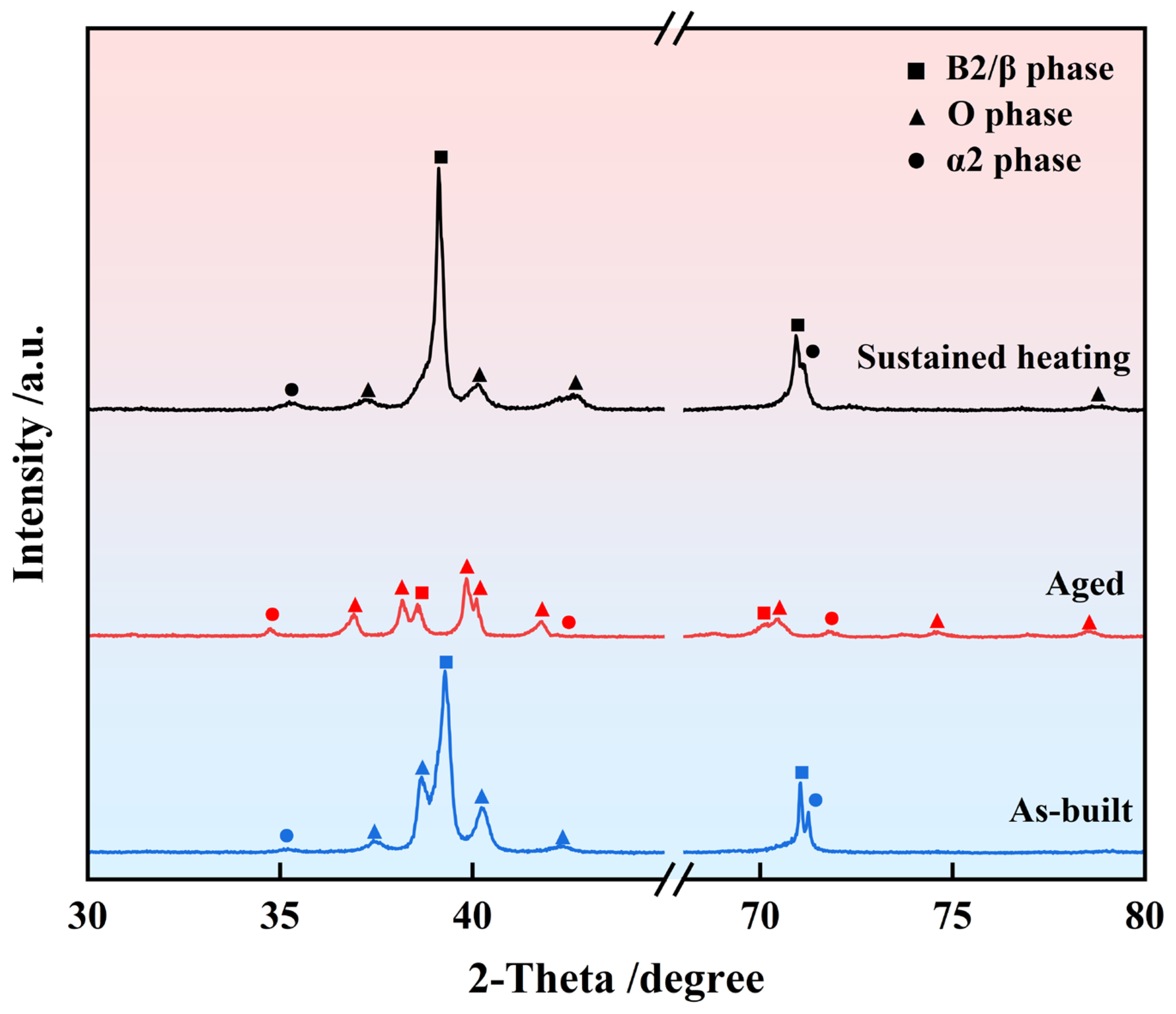
Figure 1. X-ray diffraction patterns of laser melting-deposited samples.
Crystals 15 00910 g001
Figure 2. SEM micrographs showing (a) the macroscopic morphology of the as-built samples, with the green dashed circle indicating the coarse O phase, and the high magnification SEM images showing (b) the O phase at grain boundaries and (c) within the grain interiors. The yellow arrows indicate lamellar O, the yellow circles denote acicular O, and the green boxes highlight the uniform lamellar O phase. For the aged samples, SEM images show (d) the macroscopic morphology with the dashed lines separated the fine-phase and coarse-phase regions, (e) the magnified fine-phase region, and (f) the magnified coarse-phase region.
Crystals 15 00910 g002
Figure 3. SEM microstructures near the grain boundaries show (a) the discontinuous precipitation of α2 phase along the grain boundaries in the as-built sample, indicated by green arrows; (b) the abnormally coarsened B2/O phases and (c) partially dissolved grain boundaries in the aged sample, highlighted by orange ellipses; (d) a magnified view of the dissolved grain boundary shows the growth of lamellar O phase, where the blue line marks the dissolved grain boundary region and the yellow dashed line indicates the formed lamellar O phase; (e) the morphology of abnormally coarsened B2/O phases and related elemental maps of (f) Ti, (g) Al, and (h) Nb.
Crystals 15 00910 g003
Figure 4. SEM micrographs of the internal cyclically heated sample illustrate (a) the uniform macrostructure within the grains and (b) the O-phase morphology; (c) the grain boundary macrostructure and (d) the morphology of the O phase; (e) the O-phase structure together with elemental maps of (f) Ti, (g) Al, and (h) Nb.
Crystals 15 00910 g004
Figure 5. The microstructure of the as-built sample. (a) Bright-field scanning transmission electron microscopy (BF-STEM) image of the phases and (b) the BF-STEM image shows the dislocations, (c) high-angle annular dark-field scanning transmission electron microscopy (HAADF-STEM) image and the corresponding EDS elemental maps of (d) Ti, (e) Al, (f) Nb; the HRTEM images with the inserted FFT showing the diffraction pattern of (g) β/B2 phase along [001] zone axis, (h) O phase along [ 1 ¯ 14 ] zone axis, (i) α2 phase along [ 01 1 ¯ 0 ] zone axis. Green represents the β/B2 phase, blue represents the O phase, and red represents the α2 phase, while dislocations are marked with yellow dashed lines.
Crystals 15 00910 g005
Figure 6. The O phase in the aged sample (a) BF-STEM image, (b) HRTEM image with an inserted FFT showing the diffraction pattern along the [ 1 ¯ 00 ] zone axis and the corresponding STEM-EDS elemental maps of (c) Ti, (d) Al, (e) Nb, and (f) Al-Nb. (g) HAADF-STEM image of the fine-sized α2 phase and (h) the HRTEM image of the β/B2–α2 phase interface, with (i) the inserted FFT of α2 showing the diffraction pattern along the [ 1 ¯ 012 ] zone axis.
Crystals 15 00910 g006
Figure 7. The microstructure of an internal cyclically heated sample (a) BF-STEM image, and (b) dislocation morphology and the corresponding STEM-EDS elemental maps of (c) Ti, (d) Al, (e) Nb, and (f) Al-Nb. HRTEM image with an inserted FFT of (g) O phase, (h) β/B2 phase. And (i) the HAADF-STEM image with the magnified tiny B2 phase in the green circle. (j) The BF-STEM image of the dislocation morphology is magnified in the region of the acicular O phase within the orange box, (k) STEM-EDS 1D line scan of elemental distribution across the O phase in (j).
Crystals 15 00910 g007
Figure 8. (a) Room-temperature and high-temperature tensile properties of the as-built, the aged, and the internal cyclically heated sample at 650 °C; (b) Comparison of the tensile performance between the internal cyclically heated sample at (b) room temperature and (c) 650 °C with and Ti2AlNb alloys processed by PM [54,55,56,57,58], casting [31,59,60], EBAM [43,61,62], WAAM [42,63,64,65], SLM [45,66,67], and other LMD [2,68] (The same processing technique is marked by an ellipse of identical color).
Crystals 15 00910 g008
Figure 9. Displays the SEM macrograph of the room-temperature tensile fracture surface of Ti2AlNb alloy (a) as-built, (b) aged, (c) internal cyclically heated; intergranular cracking (d) as-built, (e) aged, (f) internal cyclically heated; tear ridges, dimples, and river patterns (g) as-built, (h) aged, (i) internal cyclically heated.
Crystals 15 00910 g009
Figure 10. Displays the SEM macrograph of the high-temperature (650 °C) tensile fracture surface of Ti2AlNb alloy (a) as-built, (b) aged, (c) internal cyclically heated; intergranular cracking (d) as-built, (e) aged, (f) internal cyclically heated; tear ridges, dimples, and river patterns (g) as-built, (h) aged, (i) internal cyclically heated.
Crystals 15 00910 g010
Figure 11. EBSD maps showing grain morphology: (a) as-built sample, (b) aged sample, and (c) internal cyclically heated sample; equivalent circle diameter (ECD) distributions display the variation in grain size for (d) as-built sample, (e) aged sample, and (f) internal cyclically heated sample; and the aspect ratio and its distribution trends indicate the tendency of grain equiaxialization in (g) as-built sample, (h) aged sample, and (i) internal cyclically heated sample.
Crystals 15 00910 g011
Table 1. Chemical information of Ti2AlNb alloy powder (at.%).
MaterialTiAlNbFeCHO
Ti2AlNbBal.11.0644.030.060.0040.00280.054
Table 2. LMD processing parameters of Ti2AlNb.
Experimental ParametersAs-BuiltAgedSustained Heating
Laser power (W)160016001600
Scanning velocity (mm/s)555
Layer thickness (mm)0.60.60.8
Power feeding rate (rpm/min)0.60.60.6
Inter-layer waiting time (s)606060
Disclaimer/Publisher’s Note: The statements, opinions and data contained in all publications are solely those of the individual author(s) and contributor(s) and not of MDPI and/or the editor(s). MDPI and/or the editor(s) disclaim responsibility for any injury to people or property resulting from any ideas, methods, instructions or products referred to in the content.