Abstract
A simple and efficient approach to spatially addressed polychromatic modulation of light polarization using a photopatterned nematic liquid crystal film is proposed and investigated. In particular, we demonstrate linear polarization structuring of the broadband probe beam, including the formation of polarization singularities under the adiabatic propagation of linearly polarized light, which is achieved through in situ, rewritable photoalignment of nematic liquid crystal by a pump beam. This opto-optical control of polarization does not involve dynamic phase modulation and enables spatially resolved polarization patterning of broadband linearly polarized light in real time.
1. Introduction
The rapid development of liquid crystalline materials and devices over the last several decades has transformed our view of optical elements, from conventional displays [1] to advanced optical modulators [2,3,4,5]. Liquid crystals (LCs) combine seemingly contradictory properties, such as fluidity and strong anisotropy of physical properties, which make them highly responsive to external fields. LC anisotropy originates from partial long-range molecular ordering, defined by a unit vector called the director, which usually coincides with the optical axis. An external electric field causes deformation of the LC director field and consequent modulation of the effective refractive index and, hence, the dynamic phase of light. Thus, the electro-optical response of LCs is the key effect underlying most of their applications [6]. In particular, this approach has proven to be effective in the development of LC-based spatial light modulators (SLMs) used for the phase control of light [4].
Typical SLMs can control not only the light phase, but also the polarization, enabling the formation of linear polarization patterns [7,8,9] or even full control of polarization [10]. At present, SLMs are widely employed for the generation of structured, or topological, light beams [11,12,13]. However, the drawback of these spatial polarization control approaches is that they rely on dynamic phase modulation, which inherently depends on the light wavelength. Consequently, all such methods are limited to a narrow spectral range of modulated light.
In contrast to the dynamic phase, which is typically utilized and modulated by SLMs, the geometric phase is associated with light polarization modulation and is independent of the light wavelength [3,14,15]. This polychromatic property is especially important in the case of spectrally broadband light, such as femtosecond light pulses [16]. One of the most effective approaches to creating and controlling the geometric phase is the fabrication of LC films with patterned substrates.
Photoalignment [17,18], i.e., light-induced modification of the surface alignment of LC films, is considered one of the most effective approaches to adjust the LC orientation pattern and thus adapt the geometric phase of the propagating or reflecting light beams [8,9]. The LC alignment direction on a substrate depends on the polarization of the incident writing light beam: typically, for azobenzene photoalignment materials, the easy axis is aligned perpendicularly to the light polarization [19]. Alignment patterns formed by azobenzene layers can be rewritten multiple times, providing a means of constructing tunable optical elements [20,21,22,23,24,25] and electronic papers [26,27,28], as well as enabling optical control of LC colloids [29] through the manipulation of topological defects [30]. Broadband geometric phase modulation can also be used for polarization control when light beams modulated in photopatterned LCs interfere with each other [31].
Here, we propose a simple and robust approach for spatial–temporal polychromatic structuring of light polarization including the generation of vector fields. This method is based on the effect of adiabatic light propagation through twisted anisotropic media [32]. If the twist angle of the optical axis is much smaller than the dynamic phase shift (Mauguin limit), the polarization plane rotates in the same manner as the optical axis [33]. Therefore, when the Mauguin condition is satisfied, the polarization rotation angle is determined exclusively by the rotation angle of the LC cell director, regardless of the wavelength of light. The extraordinary and ordinary light waves follow the rotating optical axes of the LC. If the input substrate of the LC cell is uniformly aligned and the output substrate is patterned, a light beam with uniform linear polarization along the input substrate alignment will acquire the same polarization pattern as the director alignment on the output substrate [34]. Our goal is to demonstrate the feasibility of this approach for generating linear polarization patterns and for real-time polychromatic control of the probe beam polarization by combining the Mauguin regime in a nematic LC with rewritable photoalignment on one of the LC substrates.
2. Materials and Methods
We used a commercially available nematic liquid crystal E7 (Qingdao Grant Winton Int, Qingdao, China). The LC cell was composed of two glass substrates with one passive and one photoresponsive alignment layer, separated by Teflon stripes with a thickness of m. The phase shift between the extraordinary and ordinary light waves, , where the light wavelength is m and , satisfies the criterion for adiabatic light propagation in the LC cell [32]. To prepare the passive alignment layer, a 1 wt % solution of polyimide (PI2525) in N-methyl-2-pyrrolidone (CAS 874-50-4, Merck Sigma-Aldrich, Darmstadt, Germany) was spin-coated onto the substrate, followed by curing in an oven at 250 °C for one hour and subsequent unidirectional rubbing. As the photoalignment material, poly[1-[4-(3-carboxy-4-hydroxy-phenylazo)benzenesulfonamido]-1,2-ethanediyl, sodium salt] (PAzo, CAS 219957-04-7, Merck Sigma-Aldrich) was used [35]. A 0.5 wt % solution of PAzo in N,N-dimethylformamide was spin-coated, followed by curing in an oven at 100 °C. Before filling the LC cell, it was illuminated from the side of the PAzo-coated substrate for 10 min with an ultraviolet light-emitting diode, with a luminescence peak at close to the absorption maximum of the photoalignment material, and an optical power of , through a linear polarizer with an axis oriented perpendicular to the polyimide rubbing direction. The liquid crystal was then filled into the LC cell by capillary forces at room temperature. The LC film exhibited a uniform planar alignment because the PAzo photoalignment direction is perpendicular to the polarization direction.
The optical setup consisted of a continuous-wave semiconductor laser (OBIS LX, Coherent, Saxonburg, PA, USA) operating at a wavelength of , used as a pump beam for manipulation of the LC photoalignment (Laser 1, Figure 1). The wavelength corresponds to the edge of the spectral absorption peak of the PAzo material [35], while still being efficient for photoalignment and lying within the spectral range considered safe for the spatial light modulator (SLM). The light beam passed through a 5× beam expander, and the central part of the beam was used for photoalignment. The light intensity was 64 mW/cm2. The angle of the pump beam polarization plane rotation was controlled by a combination of a commercial SLM (Meadowlark Optics, Longmont, CO, USA) placed between a pair of crossed quarter-wave plates (QWP1,2) oriented at with respect to the slow axis of the SLM.
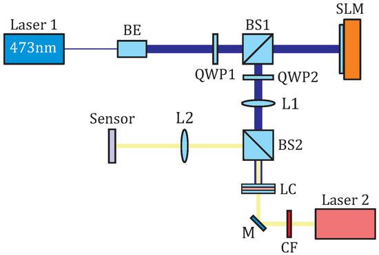
Figure 1.
Experimental setup for dynamic polarization control. The pump beam ( nm) is used for LC photoalignment, while the broadband light from a supercontinuum laser (2) with a set of light filters serves as the probe beam. BE, BS, M, and CF are beam expander, non-polarized beam splitter, mirror, and long-pass color filter, respectively. Interference filters can be used instead of long-pass color filters.
Note that, if an SLM pixel with coordinates (l, m), where l and m are integers corresponding to the row and column indices of the pixel, respectively, can be considered as a phase retarder with a phase shift between extraordinary () and ordinary () light waves, the Jones matrix for the pixel placed between crossed QWPs is calculated by multiplying the Jones matrix for the phase retarder and the waveplates as
where the matrix is a rotation matrix at the angle , multiplied by the dynamic phase term [7]. To avoid redistribution of the light intensity due to diffraction caused by phase modulation, the sample was placed in the image plane of the SLM screen using lens L1 in a configuration.
Thus, the linearly polarized light beam passed through the beam expander (BE), the first quarter-wave plate (QWP1), forming circular polarization, a non-polarizing beam splitter (BS1), and the second quarter-wave plate (QWP2), forming a polarization tilt angle of . Recalling that the photoalignment direction is perpendicular to the polarization direction, the presented optical approach enables the creation of a patterned alignment with the azimuthal tilt of the easy axis [19], given by , on the photoresponsive upper substrate of the LC cell.
The probe beam (Laser 2, Figure 1), with a diameter of mm, from a supercontinuum laser (SuperK EVO HP, NKT Photonics, Birkerod, Denmark), linearly polarized parallel to the polyimide rubbing direction on the bottom substrate, passed through a long-pass color filter (), the LC sample, and a non-polarizing beam splitter (BS2). The spectrum of the probe light beam is characterized by a spectral window from 590 nm to 740 nm. Additional interference color filters were used instead of the long-pass filter if necessary. The light power of the probe beam was 5 mW without interference filters and 30–120 W with any of the interference filters. The polarization camera (Alkeria Celera C5S-MP, Cascina, Italy) was placed in the image plane of the sample using lens L2 in a configuration.
The presented optical setup allowed us to investigate the formation of polarization patterns of the broadband probe light beam (or of relatively spectrally narrow beams using interference filters) under structured pump beam irradiation, which controlled the LC photoalignment.
The following procedure was used to investigate the properties of probe light polarization. The tilt angle of the long axes of the polarization ellipses (Angle of Linear Polarization, AoLP) and the degree of linear polarization (DoLP), which corresponds to the ratio of the axes of a polarization ellipse, are calculated from the intensities , , , and , corresponding to the polarization axes tilted at , , , and as
where
To evaluate the similarity of AoLP distributions for theoretically calculated and experimentally obtained polarization patterns, the Pearson correlation coefficient was calculated as
where is the covariance between and distributions, and and are the standard deviations of and , respectively, calculated over the whole image [36].
3. Results and Discussions
By rotating the polarization plane of the pump beam by a variable angle (Figure 2a,e), where is the polar angle in a polar coordinate system, the resulting polarization patterns (Figure 2b,f) exhibit singularities characterized by topological defects with charge Q. For demonstration, we chose the corresponding phase distributions to achieve and .
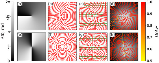
Figure 2.
Light polarization modulation of a probe beam using spatially addressable photoalignment in a nematic liquid crystal: (a,e) calculated distributions of phase shift on the SLM, (b,f) corresponding polarization of the pump light, and (c,g) easy-axis alignment on the photosensitive (red lines) and passive substrates (green lines). (d,h) Experimental images of the intensity distributions of the probe light beam (with an interference filter at 530 nm) overlapping with lines visualizing the long axes of the polarization ellipses. The image size is 2.6 mm. Exposure time of the pump beam is 300 s. Color corresponds to the degree of linear polarization (DoLP).
The pump beam induces photoalignment of the upper LC substrate (Figure 2c,g). The distributions of the LC director fields on the photopatterned substrates are characterized by singularities with topological charges and . This leads to corresponding modulation of the polarization distributions of the probe beam (Figure 2d,h). The polarization rotation of the extraordinary light wave follows the twisted director configuration when propagating in the LC bulk, which arises from the angular difference between the alignment directions on the top and bottom substrates (Figure 2c,g). The corresponding polarization distributions of the probe beams can be described as vector fields with topological charges and . Dark lines in the intensity distributions arise from LC defect lines in the bulk of the LC film, which appear due to the opposite signs of the LC twist on both sides of the disclination line [30]. These lines correspond to the director rotation between the alignment directions on the two LC cell substrates (Figure 2c,g).
Figure 3a–f illustrates the time-dependent formation of a polarization pattern with topological charge in the probe beam under sample irradiation by a pump beam having a polarization pattern with topological charge . The dark line, which forms due to light scattering in the LC defect, appears when the polarization pattern that coincides with the easy-axis alignment on the upper substrate is nearly fully developed (Figure 3d–f). The polarization pattern is considered to be in a steady state if changes by less than 0.01 during 1 min.
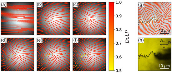
Figure 3.
(a–f) Formation of a polarization singularity with topological charge . Experimental images of the probe light intensity distributions of the broadband probe beam overlapping with lines visualizing the long axes of the polarization ellipses (the color of the lines corresponds to the degree of linear polarization, DoLP) at different times of pump light exposure: t = (a) 0 s, (b) 60 s, (c) 120 s, (d) 180 s, (e) 240 s, and (f) 300 s. The image size of (a–f) is 2.6 mm. (g,h) Experimental images of the probe light intensity distributions in the central part of the LC structure after pump beam irradiation, obtained with an optical microscope equipped with (g) a polarized camera and (h) a color camera. The lines in (g) represent the long axes of the polarization ellipses.
After the photoalignment procedure described above, we investigated the optical textures and the polarization of the output light in the central part of the LC structure using a polarized optical microscope (Leica DMi8, Leica, Leica Camera AG, Wetzlar, Germany) with a objective. The microscope was equipped with either a polarized camera or a color camera (Amscope MU1803, Amscope, Irvine, CA, USA). In the first case, we demonstrate the intensity pattern overlapped with the polarization distribution (Figure 3g). In the second case, the microscope texture of the sample between the crossed polarizers is shown (Figure 3h). The input light polarization of the microscope backlight, after passing through the long-pass filter, was aligned with the easy axis on the input substrate coated with a polyimide layer. The size of the inhomogeneity of the LC director and, consequently, the polarization singularity core is even smaller than the pixel size of the SLM (∼m) due to continuous director deformations.
The alignment patterns on the photoresponsive layer of the LC cell can be changed multiple times by altering the polarization pattern of the pump beam (Figure 4). Starting from a uniform alignment on the photoresponsive layer, coinciding with the alignment on the polyimide-coated substrate, the pattern with was obtained using the aforementioned procedure (Figure 4a,b). Then, a uniform polarization pattern of the pump beam was used to return the sample to its initial state, although with some artifacts of the residual LC defect line (Figure 4c) due to the slight non-uniformity of the polarization. The pattern with was then obtained using the corresponding polarization pattern of the pump beam (Figure 4d). This sequence of different polarization patterns demonstrates the possibility of using the sample as a re-writable linear polarization modulator with switchable states.
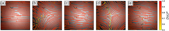
Figure 4.
Experimental images of the probe light intensity distributions of the broadband probe beam overlapping with lines visualizing the long axes of the polarization ellipses (the color of the lines corresponds to the degree of linear polarization, DoLP). The image size is 2.6 mm. The pump light, with consequently changed (a–d) polarization patterns with singularities Q = (b) −1/2, (d) −1 and without singularities (a,c,e), was used. The exposure time for each pattern is t = (a) 0 min, (b) 7 min, (c) 7 min, (d) 12 min, and (e) 20 min.
To ensure additionally that the polarization patterns shown in Figure 4b,d are the same for any light wavelength, we used the interference filters at 495 nm, 530 nm, 550 nm, 574 nm, 600 nm, and 641 nm, where the full width at half maximum is ≈10 nm, and calculated the correlation coefficients and DoLP averaged over the region of interest. The correlation coefficient for the tilt angle distribution of the long axes of the polarization ellipses was found to be for both and . At the same time, the degree of linear polarization averaged over the region of interest is for both and , for all wavelengths. The weak depolarization effect can be explained by light scattering in the region of the LC defect.
4. Conclusions
An opto-optical approach to generating linear polarization patterns, including polarization singularities of various topological charges, in a polychromatic light fields is demonstrated. Spatially inhomogeneous rotation of the polarization plane is provided by adiabatic light propagation in a twisted nematic LC, oriented by patterns written in a photosensitive layer. The effect of controlling the polarization distribution is observed across a wide spectral range and is, in principle, not limited at the long-wavelength edge of the spectrum. This property is particularly important for structuring broadband light beams. Adiabatic propagation of the extraordinary wave does not involve phase modulation, thereby avoiding additional distortions of the wavefront caused by dynamic phase modulation. Qualitative analysis of the vector fields shows good agreement with the predicted patterns. However, the LC defect lines, formed in photopatterned LCs, locally affect the intensity and polarization distributions.
The results demonstrate the efficiency of in situ rewritable photoalignment of nematic liquid crystals for polychromatic, spatially addressed polarization modulation.
Author Contributions
Conceptualization, S.A.S.; methodology, M.R. and V.L.G.; software, E.G.; validation, E.G., H.H. and H.H.H.; formal analysis, E.G.; investigation, E.G., H.H., S.A.S. and H.H.H.; resources, M.R. and V.L.G.; data curation, E.G.; writing—original draft preparation, S.A.S. and T.O.; writing—review and editing, M.R., V.L.G., T.O., E.G. and S.A.S.; visualization, E.G.; supervision, M.R.; project administration, V.L.G.; funding acquisition, V.L.G. All authors have read and agreed to the published version of the manuscript.
Funding
The research was supported by the Higher Education and Science Committee of MESCS RA (Research Project № 23IRF-1C08).
Data Availability Statement
The original contributions presented in this study are included in the article. Further inquiries can be directed to the corresponding author.
Conflicts of Interest
The authors declare no conflicts of interest.
References
- Kobayashi, S.; Miyama, T.; Akiyama, H.; Ikemura, A.; Kitamura, M. Development of liquid crystal displays and related improvements to their performances. Proc. Jpn. Acad. Ser. B 2022, 98, 493–516. [Google Scholar] [CrossRef]
- Bégel, L.; Khodadad, B.; Galstian, T. Adaptive lens for foveal vision, imaging, and projection over large clear apertures. Opt. Express 2023, 31, 2877–2891. [Google Scholar] [CrossRef]
- Tabiryan, N.V.; Roberts, D.E.; Liao, Z.; Hwang, J.; Moran, M.; Ouskova, O.; Pshenichnyi, A.; Sigley, J.; Tabirian, A.; Vergara, R.; et al. Advances in Transparent Planar Optics: Enabling Large Aperture, Ultrathin Lenses. Adv. Opt. Mater. 2021, 9, 2001692. [Google Scholar] [CrossRef]
- Yang, Y.; Forbes, A.; Cao, L. A review of liquid crystal spatial light modulators: Devices and applications. Opto-Electron. Sci. 2023, 2, 230026. [Google Scholar] [CrossRef]
- Zemska, Z.; Galstian, T. Simple electrically tunable liquid crystal spatial phase modulator. Opt. Express 2023, 31, 5388–5398. [Google Scholar] [CrossRef] [PubMed]
- Kelly, S.; O’Neill, M. Liquid crystals for electro-optic applications. In Handbook of Advanced Electronic and Photonic Materials and Devices; Elsevier: Amsterdam, The Netherlands, 2001; pp. 1–66. [Google Scholar] [CrossRef]
- Davis, J.A.; McNamara, D.E.; Cottrell, D.M.; Sonehara, T. Two-dimensional polarization encoding with a phase-only liquid-crystal spatial light modulator. Appl. Opt. 2000, 39, 1549–1554. [Google Scholar] [CrossRef] [PubMed]
- Wu, W.; Wang, C.; Pivnenko, M.; Chang, X.; Chu, D. Liquid-crystal-based diffractive optical elements with high Pancharatnam-Berry phase accuracy for holographic displays fabricated using an optimized liquid crystal on silicon device. Appl. Opt. 2024, 64, B13–B19. [Google Scholar] [CrossRef]
- Yang, C.; Sahoo, A.K.; Shen, Y.; Song, P.; Lee, C. Full-Spectrum Tunable and Handedness Invertible Geometric Phase Elements in Nanomotor-based Spiral Superstructures. Adv. Opt. Mater. 2025, 13, 2500590. [Google Scholar] [CrossRef]
- Moreno, I.; Davis, J.A.; Hernandez, T.M.; Cottrell, D.M.; Sand, D. Complete polarization control of light from a liquid crystal spatial light modulator. Opt. Express 2011, 20, 364–376. [Google Scholar] [CrossRef]
- Rosales-Guzmán, C.; Bhebhe, N.; Forbes, A. Simultaneous generation of multiple vector beams on a single SLM. Opt. Express 2017, 25, 25697–25706. [Google Scholar] [CrossRef]
- Laxminarayan; Allam, S.R.; Omatsu, T.; Kumar, P. Singularity transformation through single-pass phase modulation of light. Sci. Rep. 2025, 15, 8007. [Google Scholar] [CrossRef]
- Gao, W.; Zhou, Y.; Li, X.; Zhang, Y.; Zhang, Q.; Li, M.; Yu, X.; Yan, S.; Xu, X.; Yao, B. Topological light field: From singular to skyrmionic optics and beyond. J. Opt. 2025, 27, 083001. [Google Scholar] [CrossRef]
- Rafayelyan, M.; Tkachenko, G.; Brasselet, E. Reflective Spin-Orbit Geometric Phase from Chiral Anisotropic Optical Media. Phys. Rev. Lett. 2016, 116, 253902. [Google Scholar] [CrossRef]
- Brasselet, E. Tunable High-Resolution Macroscopic Self-Engineered Geometric Phase Optical Elements. Phys. Rev. Lett. 2018, 121, 033901. [Google Scholar] [CrossRef]
- Gökce, B.; Li, Y.; Escuti, M.J.; Gundogdu, K. Femtosecond pulse shaping using the geometric phase. Opt. Lett. 2014, 39, 1521–1524. [Google Scholar] [CrossRef][Green Version]
- Yaroshchuk, O.; Reznikov, Y. Photoalignment of liquid crystals: Basics and current trends. J. Mater. Chem. 2011, 22, 286–300. [Google Scholar] [CrossRef]
- Hegde, G.; Komitov, L. Tuning and turning of the liquid crystal alignment by photosensitive composites. Liq. Cryst. 2021, 48, 2117–2129. [Google Scholar] [CrossRef]
- Chigrinov, V.G.; Kozenkov, V.M.; Kwok, H. Photoalignment of Liquid Crystalline Materials: Physics and Applications; Wiley: Hoboken, NJ, USA, 2008. [Google Scholar] [CrossRef]
- Shvetsov, S.A.; Emelyanenko, A.V.; Bugakov, M.A.; Boiko, N.I.; Zyryanov, V.Y. Photo-orientation of nematic liquid crystal without preliminary cell surface treatment. Opt. Mater. Express 2019, 9, 2595–2600. [Google Scholar] [CrossRef]
- Quiroga, J.A.; Canga, I.; Alonso, J.; Crespo, D. Reversible Photoalignment of Liquid Crystals: A Path toward the Creation of Rewritable Lenses. Sci. Rep. 2020, 10, 5739. [Google Scholar] [CrossRef] [PubMed]
- McGinty, C.P.; Kołacz, J.; Spillmann, C.M. Large rewritable liquid crystal pretilt angle by in situ photoalignment of brilliant yellow films. Appl. Phys. Lett. 2021, 119, 141111. [Google Scholar] [CrossRef]
- Chigrinov, V.; Kudreyko, A.; Guo, Q. Patterned Photoalignment in Thin Films: Physics and Applications. Crystals 2021, 11, 84. [Google Scholar] [CrossRef]
- Kudreyko, A.; Chigrinov, V.; Hegde, G.; Chausov, D. Photoaligned Liquid Crystalline Structures for Photonic Applications. Crystals 2023, 13, 965. [Google Scholar] [CrossRef]
- Ropač, P.; Hsiao, Y.; Berteloot, B.; Ussembayev, Y.; Nys, I.; Ravnik, M.; Neyts, K. Liquid Crystal 3D Optical Waveguides Based on Photoalignment. Adv. Opt. Mater. 2024, 13, 2402174. [Google Scholar] [CrossRef]
- Chigrinov, V.G.; Kudreyko, A.A.; Podgornov, F.V. Optically Rewritable Liquid Crystal Displays: Characteristics and Performance. Crystals 2021, 11, 1053. [Google Scholar] [CrossRef]
- Chigrinov, V.; Kudreyko, A.; Sun, J. Photosensitive Alignment: Advanced Electronic Paper-Based Devices. Crystals 2022, 12, 364. [Google Scholar] [CrossRef]
- Chigrinov, V.; Kudreyko, A.; Sun, J. Flexible Optically Rewritable Electronic Paper. Crystals 2023, 13, 1283. [Google Scholar] [CrossRef]
- Asilehan, Z.; Tang, W.; Zhang, J.; Chen, Z.; Wang, R.; Shi, Q.; Song, G.; Jiang, J.; Zhang, R.; Peng, C. Light-driven dancing of nematic colloids in fractional skyrmions and bimerons. Nat. Commun. 2025, 16, 1148. [Google Scholar] [CrossRef]
- Jiang, J.; Ranabhat, K.; Wang, X.; Rich, H.; Zhang, R.; Peng, C. Active transformations of topological structures in light-driven nematic disclination networks. Proc. Natl. Acad. Sci. USA 2022, 119, e2122226119. [Google Scholar] [CrossRef]
- Rafayelyan, M.; Brasselet, E. Spin-to-Orbital Angular Momentum Mapping of Polychromatic Light. Phys. Rev. Lett. 2018, 120, 213903. [Google Scholar] [CrossRef]
- Sit, A.; Di Colandrea, F.; D’Errico, A.; Karimi, E. Spatially twisted liquid-crystal devices. APL Photonics 2024, 9, 056112. [Google Scholar] [CrossRef]
- Nityananda, R. On the Theory of Light Propagation in Cholesteric Liquid Crystals. Mol. Cryst. Liq. Cryst. 1973, 21, 315–331. [Google Scholar] [CrossRef]
- Stalder, M.; Schadt, M. Linearly polarized light with axial symmetry generated by liquid-crystal polarization converters. Opt. Lett. 1996, 21, 1948–1950. [Google Scholar] [CrossRef] [PubMed]
- Petrov, S.; Chau, N.H.M.; Marinova, V.; Sun, C.C.; Hsu, K.Y.; Lin, S.H. Controllable LC anchoring on poly1-[4-(3-carboxy-4-hydroxyphenylazo) benzenesulfonamido]-1, 2-ethanediyl, sodium salt command surface. Polymer 2023, 272, 125841. [Google Scholar] [CrossRef]
- Neto, A.M.; Victorino, A.C.; Fantoni, I.; Zampieri, D.E.; Ferreira, J.V.; Lima, D.A. Image processing using Pearson’s correlation coefficient: Applications on autonomous robotics. In Proceedings of the 2013 13th International Conference on Autonomous Robot Systems, Lisbon, Portugal, 24 April 2013; pp. 1–6. [Google Scholar] [CrossRef]
Disclaimer/Publisher’s Note: The statements, opinions and data contained in all publications are solely those of the individual author(s) and contributor(s) and not of MDPI and/or the editor(s). MDPI and/or the editor(s) disclaim responsibility for any injury to people or property resulting from any ideas, methods, instructions or products referred to in the content. |
© 2025 by the authors. Licensee MDPI, Basel, Switzerland. This article is an open access article distributed under the terms and conditions of the Creative Commons Attribution (CC BY) license (https://creativecommons.org/licenses/by/4.0/).