Abstract
Concentrated Solar Power (CSP) technology is advancing toward higher operating temperatures and lower costs: current systems operate at 565 °C, while next-generation systems are targeted to reach 800 °C to overcome efficiency limitations. In this context, low-cost, adaptable molten chloride salts have emerged as ideal heat transfer and thermal energy storage media. Metallic materials are susceptible to performance degradation under such conditions, which not only shortens equipment service life but also entails potential safety hazards. Thus, the development of alloy protection technologies resistant to molten salt corrosion has become an urgent priority for the deployment of next-generation CSP plants. Research has indicated that high-aluminum stainless steel is a promising candidate due to its unique advantages: it can form a stable Al2O3 protective film in oxygen-containing anionic environments, effectively inhibiting the dissolution of Cr, Fe, and other elements, and preventing the penetration of corrosive species. Additionally, the incorporation of magnesium-based corrosion inhibitors into MgCl2-NaCl-KCl ternary molten salt systems has been proven to be an economically viable and efficient corrosion mitigation strategy. This study focused on high-aluminum 310S heat-resistant steel, with its performance validated through targeted experiments: samples subjected to pre-oxidation at 800 °C for 2 h were immersed in a specific ternary molten salt mixture (20.4 wt.% KCl, 55.1 wt.% MgCl2, 24.5 wt.% NaCl) containing magnesium corrosion inhibitors, followed by a 600 h static corrosion test at 800 °C. The results revealed that the addition of magnesium significantly enhanced the corrosion resistance of high-aluminum 310S. These findings demonstrate that this material holds application potential in the storage tank and pipeline systems of next-generation CSP plants.
1. Introduction
Next-generation CSP plants represent a cornerstone of sustainable energy advancement, and their cost competitiveness hinges critically on enhancing the compatibility between alloy materials and thermal energy storage media [1,2]. A significant bottleneck, however, persists in practical operation: stainless steels, widely employed in CSP storage tanks and pipelines, are susceptible to thermal corrosion and high-temperature oxidation in molten salt environments, precluding their ability to meet the stringent 30-year service life requirement [3]. To tackle this challenge, extensive investigations have been conducted on the corrosion behavior of stainless steels, including 304, 310, 316, and 347, in molten salt systems. Employing static immersion tests, electrochemical analyses, and simulated thermal cycling corrosion experiments, these studies have examined material performance under diverse atmospheric conditions (temperatures ranging from 400 °C to 800 °C and exposure durations spanning tens to thousands of hours), with the aim of elucidating corrosion mechanisms, evaluating material compatibility, and identifying viable materials and mitigation strategies [4,5].
Intergranular corrosion and pitting corrosion are prevalent corrosion mechanisms for stainless steels in molten salt environments. For example, Fernandez et al. [6] observed severe intergranular corrosion in AISI 304 following 8 h of exposure to a molten salt mixture (20.4 wt.% KCl, 55.1 wt.% MgCl2, 24.5 wt.% NaCl) at 720 °C under a nitrogen atmosphere, with a measured corrosion rate as high as 8.19 mm/y. Similarly, Kondo et al. [7,8] detected intergranular corrosion on the surfaces of SS304 and SS316L after 1000 h of immersion in static fluorinated salts at 600 °C. A key degradation pathway is the selective dissolution of Cr, as reported by Sun et al. [9] in studies of 316SS and nickel-based alloys in chloride salts at 700 °C, which leads to the formation of subsurface voids. Protective oxide layers (e.g., Cr2O3) on stainless steels gradually dissolve over time, and in Cl−-rich environments, gaseous species such as HCl and Cl2 further destabilize these layers, thereby accelerating corrosion. The corrosion rates of several common stainless steels, as summarized in Table 1, underscore their vulnerability in such environments.

Table 1.
Corrosion rates of several common stainless steels.
In terms of corrosion mechanisms in molten salts, Ruiz-Cabanas et al. [10] proposed a two-stage driving process: initially, metallic alloying elements react and form oxides; subsequently, the molten salt acts as a flux, dissolving these protective oxides and, thus, accelerating material degradation. While the extent of alloy corrosion is widely recognized to be associated with alloy composition, particularly Cr, controversy remains. For instance, Williams et al. [11] argue that Cr is not a dominant factor, emphasizing the need for further investigation into the roles of other elements such as Fe, Mo, and W. Consequently, the corrosion behavior and underlying mechanisms of alloys in molten chloride salts are yet to be fully elucidated.
Corrosion processes are influenced by multiple factors, including oxygen, temperature, molten salt impurities, and atmospheric conditions [12,13]. Elevated temperatures generally accelerate corrosion, as Guo et al. [14] found that the corrosion rate and intergranular corrosion severity of 316SS in NaCl-MgCl2 increased with temperature (500–700 °C), which they attributed to the accelerated dissolution and intergranular diffusion of Cr [15]. Oxygen is another critical driver, as Gomez-Vidal et al. [16] noted that oxygen promotes the formation of oxides, which dissolve in molten chlorides to release additional O2, thereby exacerbating oxidation. Ding et al. [17] further linked O2 and H2O to the formation of MgOHCl impurities in salt, which react and release HCl to intensify corrosion. While Fernandez et al. [18] proposed a molten salt heat treatment process to mitigate contamination by O2 and H2O, conclusive evidence regarding its effectiveness across different stainless steels and superalloys is lacking. Mohan et al. [19] designed ternary chloride mixtures with different cation combinations—Na/K/Mg-Cl (24.5/20.5/55 wt.%), and experimentally verified them using differential scanning calorimetry. They proved that this mixture is stable at 700 °C and can even operate at 750 °C. Additionally, dynamic conditions may enhance corrosion rates compared to static ones, as demonstrated in tests on A516 carbon steel [20], with the thickness and morphology of oxide layers varying with operating parameters [21].
To mitigate corrosion, strategies such as surface pre-oxidation and corrosion inhibitors have been explored. Pre-oxidation leverages Al and Cr to form protective oxide layers (Al2O3, Cr2O3) on alloy surfaces, with Al2O3 exhibiting superior high-temperature stability [22,23,24,25]. Ding et al. [17] confirmed that pre-oxidized Fe-Cr-Al alloys form stable Al2O3 layers with excellent corrosion resistance in molten salts under an argon atmosphere. For molten salt optimization, the addition of Mg powder has shown promise: Wei et al. [26] reported improved corrosion resistance of 310S in salt with the introduction of 0.5 wt.% Mg, while Pradhan et al. [27] observed a 40% reduction in the corrosion rate of Inconel 617 with 1 wt.% Mg added in salt, attributed to Mg’s ability to consume oxidizing species and promote the formation of a dense MgO protective layer.
Notably, high-aluminum 310S heat-resistant steel exhibits favorable high-temperature mechanical properties, rendering it a potential candidate for CSP applications. Hu et al. [28] found that 310S annealed under high-temperature, hydrogen-containing atmospheres achieved an ultimate tensile strength of 400 MPa at 600 °C. Yu et al. [29] further demonstrated that increasing Al content in 310S enhances strength via solid solution and fine-grain strengthening, with elongation remaining stable at approximately 16% at 800 °C.
Building on these findings, this study focuses on high-aluminium 310S, aiming to enhance its corrosion resistance in molten salts through a strategy of Mg addition [30]. This approach integrates the ability of Al to form stable Al2O3 layers [31,32,33] and the role of Mg in mitigating oxidizing species [26,27], while leveraging the favorable mechanical properties of 310S [28,29], to address the long-term service challenges of alloy materials in CSP systems [34,35].
2. Experimental Methods
The experimental procedure consists of five main stages: alloy sample preparation, molten salt treatment, static corrosion testing, determination of corrosion rate, and subsequent sample preparation for cross-sectional microstructural and compositional analysis.
2.1. Alloy Sample Preparation
In the initial stage, the metal samples employed are high-aluminum 310S plates developed by our research team and authorized for mass production by Shanghai Dadong Special Steel Enterprise based on the specified alloy composition. These plates were formulated through compositional adjustments to the standard 310S alloy, specifically by increasing the Al content while correspondingly reducing the Cr content. The detailed alloy composition is presented in Table 2. The heat treatment procedure for high-aluminum 310S is as follows: A box-type resistance furnace (model SX-G16103, Shanghai Qianjun Scientific Instrument Co., Ltd., Shanghai, China) was heated from room temperature to 1000 °C at a heating rate of 10 °C/min. The samples were then placed inside the furnace, held at this temperature for 10 min, and subsequently quenched in water. The temperature was further increased to 1050 °C, and the same holding and quenching steps were repeated. Following plate production, the high-aluminum 310S underwent hot rolling processing to enhance its structural properties.
Table 2.
Composition of high-aluminum 310S.
Following heat treatment, the alloy samples were machined into specimens of dimensions 12 × 12 × 3 mm3 using wire cutting. These specimens were then ground with sandpaper ranging from grit sizes 60# to 2000#, followed by fine polishing with a diamond spray polishing agent of grain size W 2.5. Subsequently, the specimens were ultrasonically cleaned in anhydrous ethanol for 10 min and dried using a cold air blower for subsequent experimental use. The surface roughness of the alloy was examined under a microscope to ensure smoothness and the absence of scratches. Four samples were used for each time interval in every experimental group: one for material characterization and three for mass measurement.
Each surface-cleaned sample was placed in a covered Al2O3 crucible and introduced into a box-type resistance furnace. The furnace was heated at a rate of 10 °C/min to the target temperature (800 °C for pre-oxidation), followed by a holding period of 2 h. 310S-1 is the corrosion test sample without Mg powder added to the molten salt. 310S-2 is a corrosion test sample with 0.25 wt.% Mg powder added to the molten salt. Afterward, the furnace was allowed to cool naturally. Upon cooling, the dimensions of the samples were measured using a vernier caliper and a micrometer, and their masses were recorded using a JOANLAB JNB2001 electronic balance (Zhejiang, China) with a precision of 0.0001 g.
The crucibles were subjected to ultrasonic cleaning in distilled water, followed by dehydration in a box-type resistance furnace at 200 °C. This process was repeated until a constant mass was achieved, indicating complete removal of moisture. Thereafter, the crucibles were maintained at 70 °C in a vacuum drying oven for subsequent use.
2.2. Molten Salt Treatment
The chloride salts used in the experiment were analytical-grade sodium chloride, potassium chloride, and magnesium chloride, and inhibitor Mg powder, all supplied by Sinopharm Group (Shanghai, China). In order to remove the hydrate from magnesium chloride hexahydrate, a dehydration and drying process should be carried out on the chloride salt before the corrosion experiment. Each salt was placed into separate Al2O3 crucibles and dried using a multi-stage process: 117 °C for 24 h, 180 °C for 8 h, 240 °C for 2 h, 400 °C for 1 h, and 600 °C for 1 h. After drying, the salts were ground into fine powders and mixed in a weight ratio of 24.5% NaCl, 20.4% KCl, and 55.1% MgCl2 [19]. A 0.25 wt.% Mg corrosion inhibitor was then added. The final mixture was sealed in a sample bag and stored in a DZF-type vacuum drying oven at 70 °C. The XRD patterns of mixed chloride salts after the dehydration process are shown in Figure 1, and the composition of salts is in Table 3.
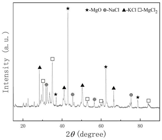
Figure 1.
The XRD of mixed chloride salts after the dehydration process.
Table 3.
Chemical composition of chloride salts.
2.3. Static Corrosion Testing
The corrosion resistance of the alloy was evaluated using a static corrosion method. Dry salt was first loaded into an Al2O3 crucible, and the test samples were vertically inserted to ensure complete immersion and suspension within the molten salt. Identical samples were placed in the same crucible to maintain consistency. Each crucible was sealed with a lid and then introduced into a muffle furnace (KSW-12-12, Beijing Kewei Yongxing Instrument Co., Ltd., Beijing, China). Five parallel specimens were arranged in each crucible to enable statistical reliability. The furnace was heated from room temperature to the target temperature of 800 °C at a controlled rate of 5 °C/min and held isothermally for a total duration of 600 h. At predetermined intervals—120 h, 240 h, 360 h, 480 h, and 600 h—one crucible was withdrawn from the furnace, and preheated chloride salt was immediately added to maintain full coverage over the sample surface, thereby minimizing volatilization losses and ensuring stable corrosive conditions. After natural cooling to room temperature, the corroded samples were carefully retrieved in sequence for subsequent analysis. Corrosion exposure time was defined as the period starting when the furnace reached 800 °C and ending upon removal of the crucible from the furnace.
2.4. Determination of Corrosion Rate
The corrosion rate was determined using the weight loss method according to ASTM G1-03 [31]. To remove corrosion products without damaging the metal substrate, samples were first boiled in water to remove residual salts. Then, a pickling solution was prepared by mixing 50 mL of nitric acid, 10 mL of hydrofluoric acid, and 440 mL of distilled water. Samples were immersed in this solution, rinsed repeatedly, and dried with anhydrous ethanol. Each sample was then weighed using an electronic balance, recording mass to four decimal places. This procedure is repeated continuously until all the oxide layer on the surface of the sample is removed. Calculate the corrosion rates of the two specimens, respectively, according to Equations (1) and (2), and take the average value for calculation to eliminate random errors.
where Δm represents the mass change in the sample before and after corrosion, g; mB is the critical value of the mass loss of the corroded sample after pickling, which corresponds to the mass at which the oxide layer is just completely removed without any loss of the substrate, g; m0 is the initial weight of the sample, in g; K is a constant, the value is 8.76 × 107 µm/y; S0 represents the initial surface area of the sample, cm2, ρ is the density of the steel, g/cm3, and the value is 7.98 g/cm3, and t is the corrosion time of the sample, h.
2.5. Subsequent Sample Preparation for Cross-Sectional Microstructural and Compositional Analysis
The corrosion rate was calculated from the collected data and expressed in µm/year. The samples were processed into surface and cross-sectional specimens for analysis. Surface samples were first rinsed with distilled water and then ultrasonically cleaned with ethanol until all residual molten salt was removed without damaging the oxide layer. After drying, they were sealed for further analysis. For cross-sectional preparation, the samples were embedded in epoxy resin and ground stepwise using sandpaper ranging from 120# to 5000# grit until the substrate was fully exposed. After polishing, the samples were ultrasonically cleaned with anhydrous ethanol, dried, and stored under sealed conditions. Surface and cross-sectional samples were analyzed using scanning electron microscopy (SEM: Axia ChemiSEM, Thermo Fisher Scientific, Shanghai, China) to assess corrosion depth and morphology. Elemental composition and distribution were determined via energy-dispersive X-ray spectroscopy (EDS). EDS is usually used in conjunction with SEM, and can quickly perform qualitative analysis of the types of elements in a sample, quantitatively determine the content of elements, and present the spatial distribution of elements in combination with microscopic imaging. Optical microscopy (OM) was also used for surface observation. Phase composition of the corrosion products was analyzed by X-ray diffraction (XRD: HaoYuan Instrument, Dandong, China, D/Max-2400 type).
3. Experimental Results
3.1. Corrosion Performance and Surface Composition of High-Aluminium 310S Under Magnesium Corrosion Inhibitor Conditions
According to Figure 2, it was found that the corrosion rate of the sample with Mg added was significantly lower than that of the sample without Mg added, and it decreased significantly after 240 h of corrosion. After 600 h, the corrosion rate reached 3983 μm/y, which was lower than the results of other related studies.
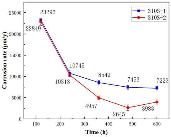
Figure 2.
The corrosion rate of high-aluminium 310S in chloride salts: 310S-1 without Mg and 310S-2 with Mg.
In Figure 3, the 310S-1 pre-oxidized sample (oxidized at 800 °C for 2 h) was placed in a chloride salt environment without added Mg. After exposure at 800 °C for 600 h, surface corrosion products were analyzed using XRD as follows: At 120 h, detected phases included MgO, MgFe23+O4, MgNiO2, Al2O3, and molten salts such as KCl and NaCl. These results suggest that alloying elements began reacting with the environment early on, forming compounds like ferrates, nickelates, and magnesium oxide. At 240 h, the phases identified were (Al0.9Cr0.1)2O3, MgFe23+O4, MgO, and Al2O3. During this stage, chromium diffused outward and reacted with oxygen to form chromium-aluminum spinel. At 360 h, observed phases were MgFe23+O4, MgNiO2, Al2O3, Fe3O4, and MgO, indicating increased Mg participation and the formation of new alloy phases. Iron oxides also transformed into more stable iron(III) oxide. By 480 h, the main components were Al2O3, Fe2O3, SiO2, and MgCrO4, showing further oxidation of iron and the appearance of silicon-based oxides. At 600 h, corrosion products mainly consisted of FeCr2O4, Al2O3, MgCrO4, MgNiO2, Fe3O4, and MgO. The continued presence of Fe- and Mg-containing spinels indicates their stability under these conditions. The emergence of FeCr2O4 and MgCrO4 confirms Cr migration and reaction with oxygen and chlorine.
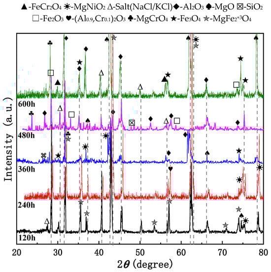
Figure 3.
XRD patterns of 310S-1 and subsequently exposed to chloride salts without Mg at 800 °C for 600 h.
From the overall reaction trend analysis, it can be observed that during the corrosion process, Fe and Ni elements initially react with Mg and other elements. Subsequently, Cr participates in the reaction, followed by Al forming its corresponding oxide. Finally, Si also engages in the reaction, producing silicon oxide. Additionally, the oxidation state of Fe gradually transitions from a lower valence state to a higher one, ultimately forming oxides such as Fe2O3 and Fe3O4. This indicates that the oxidation reaction persists throughout the entire corrosion process, with the degree of oxidation continuously intensifying. In the final stage, newly formed phases coexist with stable phases. Over time, new compound phases continue to form, such as MgCrO4 and FeCr2O4. Meanwhile, certain phases, including Al2O3 and MgO, are present at multiple time intervals, suggesting their relative stability in this corrosive environment.
Figure 4 presents the XRD results of the 310S-2 pre-oxidized sample (800 °C for 2 h), which was subsequently exposed to a chloride salt containing Mg at 800 °C for durations ranging from 120 to 600 h in an atmospheric environment. The evolution of corrosion products is summarized as follows: After 120 h, Al2O3, Fe2O3, SiO2, MgAl2O4, (Mg, Fe)2SiO4, and residual KCl were identified. This confirms the successful formation of a protective Al2O3 layer through pre-oxidation. High-temperature diffusion and element interaction led to the formation of Fe2O3, SiO2, MgAl2O4, and (Mg, Fe)2SiO4. After 240 h, Fe3O4, MgO, MgCrO4, and MgSiO3 were detected, indicating further oxidation of Fe to Fe3O4 and Mg to MgO, followed by Mg’s involvement in forming MgCrO4 and MgSiO3. At 360 h, Fe3O4, AlFeO3, Al2O3, Cr2O3, and SiO2 were observed, showing continued oxidation of Fe, Al, Cr, and Si. Between 480 h and 600 h, the corrosion products stabilized, with dominant phases including: Fe3O4, MgO, MgCrO4, MgSiO3, and MgAl2O4, indicating that stable oxide phases dominate in later corrosion stages. Notably, Al2O3 was detected at multiple time points, demonstrating its high stability under these conditions. These findings suggest that prolonged high-temperature oxidation leads to progressive changes in product composition and that the diffusion rate of metal elements follows the order: Fe > Cr > Al > Si > Mn > Ni.
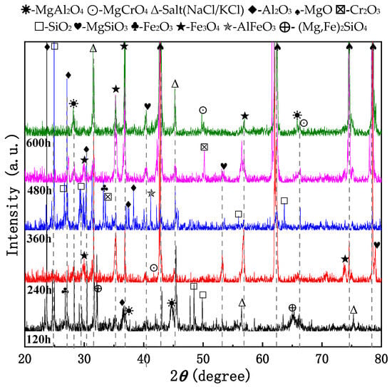
Figure 4.
The XRD pattern of 310S-2 after pre-oxidation at 800 °C for 2 h and subsequent corrosion at 800 °C in the chloride salt with Mg for 600 h.
The evolution trend of surface corrosion products under pre-oxidation conditions indicates that the composition of the products becomes increasingly complex with prolonged exposure time. During the early stage of corrosion (120–240 h), the primary detectable phases include matrix elements along with Al2O3 and Cr2O3. Fe2O3 was identified on the surfaces of both 310S-1 and 310S-2 samples following pre-oxidation at 800 °C. In the middle to later stages of corrosion (360–480 h), both samples exhibited the formation of spinel-type oxides, which were largely similar in composition.
Figure 5 shows the macroscopic morphology of 310S-2. In Figure 5a, the alloy appears to have a silvery metallic luster on the surface; In Figure 5b the 310S have been pre-oxidized at 800 °C for 2 h, a dark brown substance can be seen covering the surface; Figure 5c shows the macroscopic morphology after corrosion for 120 h–600 h, with a thick dark brown oxide layer formed on the surface. The oxide layer is more irregular in shape, and the surface is rougher after 480 h and 600 h of corrosion.
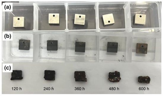
Figure 5.
Macroscopic morphology of 310S-2: (a) Alloy; (b) pre-oxidation at 800 °C for 2 h; (c) after corrosion for 120–600 h.
In Figure 6, the surface morphology of 310S-2 after corrosion for 120 h shows a distinct blackish-brown coloration, which is mainly dominated by corrosion products. Scattered white dot-like substances can be observed, which are identified as residual molten salts based on background information. In the high-magnification Figure 6b, it can be seen that the surface is overall covered with relatively dense corrosion products, forming irregular patchy areas. In some areas, obvious corrosion pits of varying sizes can be seen, distributed relatively randomly, making the surface appear uneven overall.
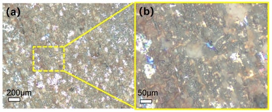
Figure 6.
Microscopic morphology of 310S-2 after corrosion for 120 h: (a) low magnification image; (b) high magnification image.
3.2. Corrosion Surface Cross-Section Morphology and Structure of High-Aluminium 310S
Figure 7 presents the cross-sectional microstructural characterization of the sample corroded in chloride salt without Mg following pre-oxidation at 800 °C for 2 h under a strain rate of 310S-1. After 120 h of exposure, cracks oriented either parallel or perpendicular to the interface were observed within the oxide layer (Figure 7a–d). The total thickness of the oxide layer reached approximately 1.57 mm, and signs of delamination were evident near the substrate. As shown in Figure 7e,f, Fe and Ni from the substrate have diffused into the oxide scale. No continuous Al2O3 layer was formed; however, relatively distinct oxide layers composed of Cr, Fe, and Mg were observed, although none exhibited a dense morphology. Furthermore, chloride salts were found to have penetrated into the matrix.
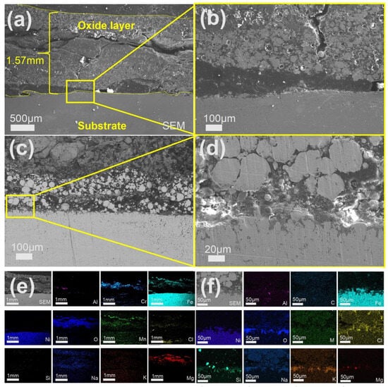
Figure 7.
Cross-sectional SEM/EDS morphology of 310S-1 corroded in chloride salt without Mg for 120 h: (a) Low magnification image; (b–d) High-magnification image; (e,f) EDS mapping.
Figure 8 shows the SEM/EDS morphology after 240 h of corrosion. Figure 8a,b indicates that the overall oxide layer is 846 µm thick, with a loose texture and large pits at the edges. The area of the oxide layer close to the substrate is relatively dense. In Figure 8b, when the observation factor is magnified, it can be seen that there is intergranular corrosion in the substrate. Figure 8c,d shows that the oxide layer is divided into several different regions. The outermost layer is composed of oxides of Mg and Fe, the middle layer is made up of oxides of Cr, Mn, and Al, and the inner layer, closest to the substrate, is Al2O3. The Cl, K, and Na of the molten salt are distributed in the oxide layer and accumulate on the surface of the substrate.
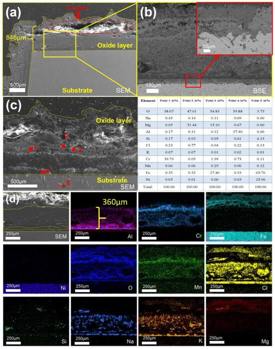
Figure 8.
Cross-sectional SEM/EDS morphology of 310S-1 corroded in chloride salt without Mg for 240 h: (a) Low magnification image; (b) is the high-multiple image of the yellow box in (a); (c) Point scanning; (d) EDS mapping.
As shown in Figure 9, after 360 h of corrosion, the total thickness of the oxide layer formed on 310S-1 reached approximately 440 µm (Figure 9a). Large pits and spalling were observed within the oxide layer (Figure 9c), and intergranular corrosion occurred in the substrate (Figure 9d). In Figure 9e, the Al2O3 layer was thickened to approximately 220 µm. In Figure 9f, point 1 corresponds to MgO, point 2 corresponds to magnesium and iron oxides, point 3 corresponds to Cr2O3, point 4 corresponds to Al2O3, and points 5–6 represent the matrix.
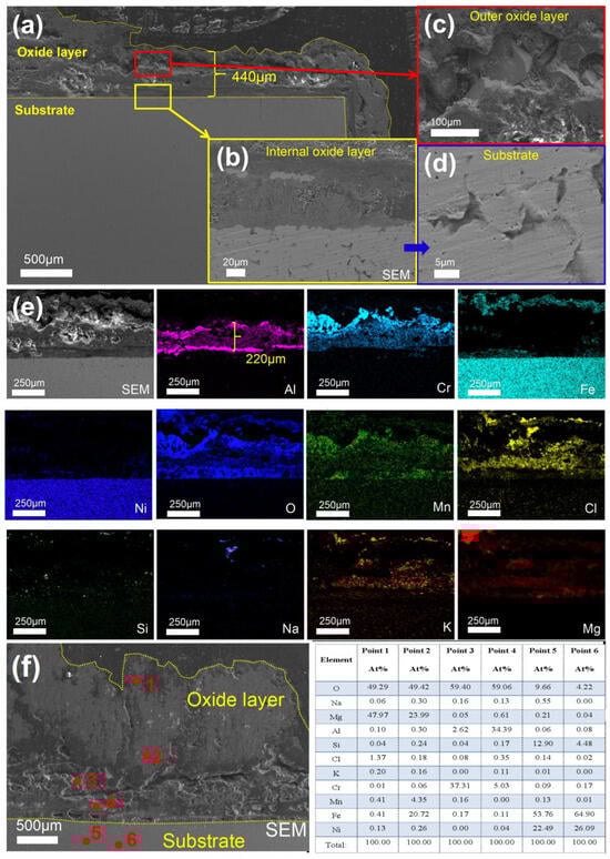
Figure 9.
Cross-sectional SEM/EDS morphology of 310S-1 corroded in chloride salt without Mg for 360 h: (a) Low magnification image; (b) is the high-multiple image of the yellow box in (a); (c) is the high-magnification image of the red box in (a); (d) SEM of matrix; (e) EDS mapping; (f) Point scanning.
As shown in Figure 10d, after 480 h of corrosion, the Al2O3 layer increased to approximately 410 µm in thickness and exhibited stratification in the middle region, where Cr and Cl elements were predominantly detected. According to the spot scan results presented in Figure 10c, in addition to MgO and Al2O3, which were also observed in the earlier stage, Si and Mn were found to accumulate on the substrate surface.
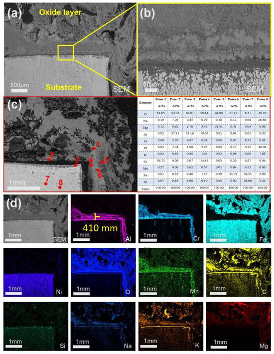
Figure 10.
Cross-sectional SEM/EDS morphology of 310S-1 corroded in chloride salt without Mg for 480 h: (a) Low magnification image; (b) is the high magnification image of the yellow box in (a); (c) Point scanning; (d) EDS mapping.
In Figure 11, after 600 h of corrosion, the matrix was more severely corroded, and the external oxide layer reached a maximum thickness of approximately 7 mm (Figure 11f). The outermost layer (point 1) was primarily composed of MgO, and the middle layer (point 2) consisted of magnesium and iron oxides, which were confirmed to be MgFe2+3O4 based on XRD analysis. Point 3 in the inner layer corresponds to Cr2O3, point 4 corresponds to Al2O3, and point 5 represents the matrix. Additionally, the thickness of the chloride salt layer embedded within the oxide layer was measured to be approximately 165 µm, indicating that molten salt continuously infiltrated into the substrate over the long-term corrosion process.
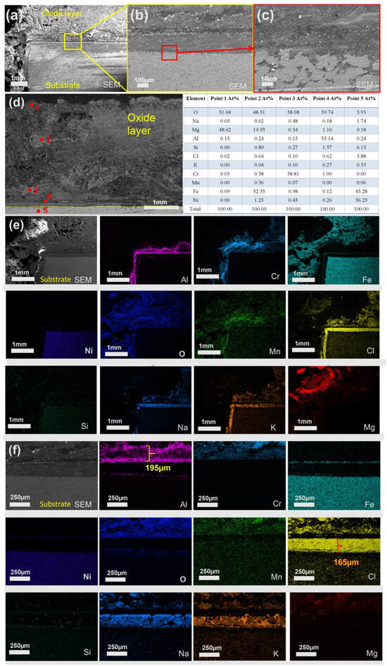
Figure 11.
Cross-sectional SEM/EDS morphology of 310S-1 corroded in chloride salt without Mg for 600 h: (a) Low magnification image; (b) is the high magnification image of the yellow box in (a); (c) is the high magnification image of the red box in (a); (d–f) EDS mapping.
Through cross-sectional analysis of the samples across five time periods, it can be observed that within 600 h, the oxide layer of the 310S-1 sample undergoes a progressive development process. Initially, the oxide layer begins to form and subsequently experiences a phase of consumption and stratification. From 480 h onward, a new growth phase commences, during which the oxide layer becomes increasingly dense. By the later stages of corrosion, the oxide layer essentially reaches a state of equilibrium and stability. The oxide layer is primarily composed of MgO, Fe2O3, Cr2O3, and Al2O3, arranged in sequence from the outermost to the innermost layer. Additionally, spinel compounds containing Mg, Fe, Cr, and Ni are observed during the later stages of corrosion.
3.3. Morphology and Structure of the Corrosion Section of High Aluminium 310S Under Mg Corrosion Inhibitor
The SEM/EDS analysis of the 310S-2 sample cross-section after pre-oxidation at 800 °C for 2 h, corroded in chloride salt with Mg for 120 h, is presented in Figure 12. As shown in Figure 12a, an oxide layer with a thickness of approximately 1 mm was formed, featuring a central pit measuring 1.5 mm × 0.5 mm. Figure 12b provides an enlarged view of the interface region. Small particulate substances are observed at the boundary between the oxide layer and the substrate, while the morphology of the substrate remains largely intact. Figure 12c displays the EDS mapping of the cross-section. The matrix is primarily composed of Fe and Ni, whereas the oxide layer mainly consists of oxides of Fe, Cr, and Al, along with Cl, Mg, K, and Na derived from the chloride salts. This suggests that molten salt constituents have penetrated into the matrix, while Fe, Cr, and Al from the matrix have diffused outward into the oxide layer.
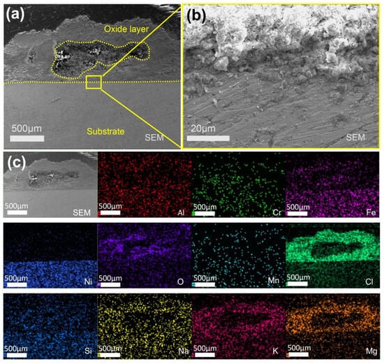
Figure 12.
Cross-sectional SEM/EDS morphology of 310S-2 corroded in chloride salt with Mg for 120 h: (a) Low magnification image; (b) is a high magnification image of the yellow box area in (a); (c) EDS mapping.
The SEM/EDS analysis of the sample after 240 h of etching is presented in Figure 13. It can be observed that, in comparison with the 120 h sample, the alloy matrix exhibits more pronounced corrosion features at this stage, with the edges displaying an irregular, serrated morphology. As shown in Figure 13c, the oxide layer primarily consists of elements such as Fe, Al, Cr, and Mn. Mg is distributed throughout the oxide layer, whereas Al and Cr tend to accumulate near the interface between the oxide layer and the matrix. Additionally, some Cl and O elements have penetrated into the matrix. Based on the atomic percentage data obtained from the point scan analysis in Figure 13d: Point 1 corresponds to Cr2O3; Points 2 and 3 correspond to Al2O3; Point 4 represents MgO; Point 5 indicates Fe3O4; Point 6 consists of Fe and Ni matrix components along with a small amount of Si and NaCl; and Point 7 mainly contains Fe and Ni elements from the matrix. It can be concluded that the oxide layer structure, from the outer surface to the inner matrix, is sequentially composed of MgO, Fe3O4, Cr2O3, Al2O3, and the metallic matrix.
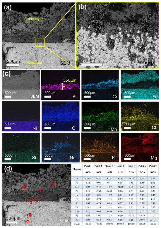
Figure 13.
Cross-sectional SEM/EDS morphology of 310S-2 corroded in chloride salt with Mg for 240 h: (a) Low magnification image; (b) is a high magnification image of the yellow box area in (a); (c) EDS mapping; (d) is point scanning of (a).
Figure 14 presents the morphology and compositional characteristics of the sample cross-section after 360 h of corrosion. Cracks are observed at the interface between the substrate and the oxide layer (Figure 14c), extending vertically downward from the substrate surface. As shown in Figure 14d, the oxide layer is predominantly composed of aluminum oxides, with thicknesses ranging from 20 to 200 µm. The highest concentration of Cl is found in the thinnest regions of the oxide layer, suggesting that chloride ions (Cl−) exert a significant destructive effect on this layer. After 480 h of corrosion, the overall thickness of the oxide layer increased to 1.723 mm, accompanied by the formation of numerous pores. Additionally, cracks parallel to the substrate surface were observed near the oxide-substrate interface, as illustrated in Figure 15a. Figure 15c reveals that the matrix has undergone severe intergranular corrosion. Energy-dispersive X-ray spectroscopy (EDS) point analysis of a localized region (Figure 15d) indicates that the matrix primarily consists of Fe and Ni, with a notable presence of chloride salts along the fine intergranular boundaries, suggesting that chloride ions have penetrated into deeper regions of the matrix along these paths. The EDS point scan results presented in Figure 15e reveal the composition of the oxide layer as follows: Point 1 corresponds to MgO; Point 2 represents a mixed oxide of Mg and Fe; Point 3 contains oxides of Fe, Cr, Al, and Si; Point 4 is identified as Al2O3; Point 5 consists of the matrix along with a relatively high concentration of O and Cl; and Point 6 corresponds to oxides of Fe and Ni with a minor contribution from Si. Based on the XRD analysis, the corrosion products in the later stages include not only simple alloy oxides such as Fe3O4 and MgO, but also more complex spinel-type compounds, such as MgCrO4, MgSiO3, and MgAl2O4.
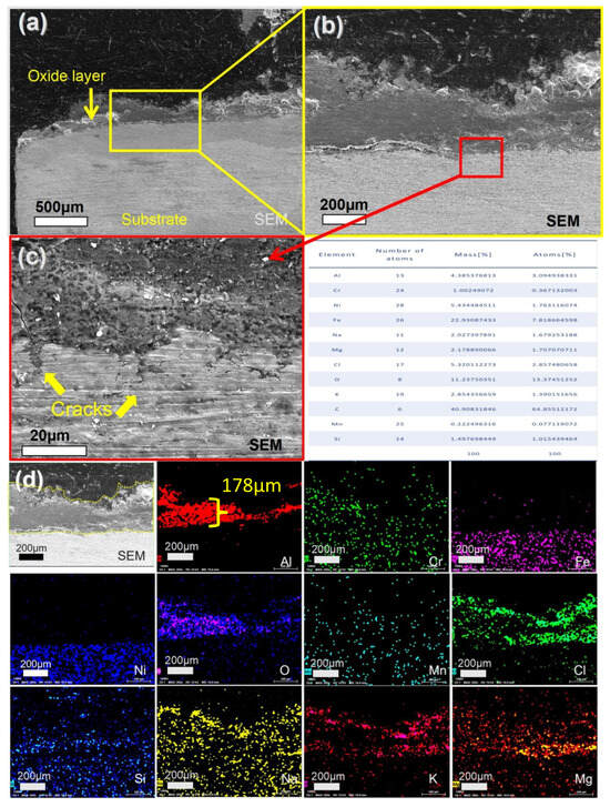
Figure 14.
Cross-sectional SEM/EDS morphology of 310S-2 corroded in chloride salt with Mg for 360 h: (a) Low magnification image; (b) is a high magnification image of the yellow box area in (a); (c) is a high magnification image of the red box area in (b); (d) is EDS mapping of (b).
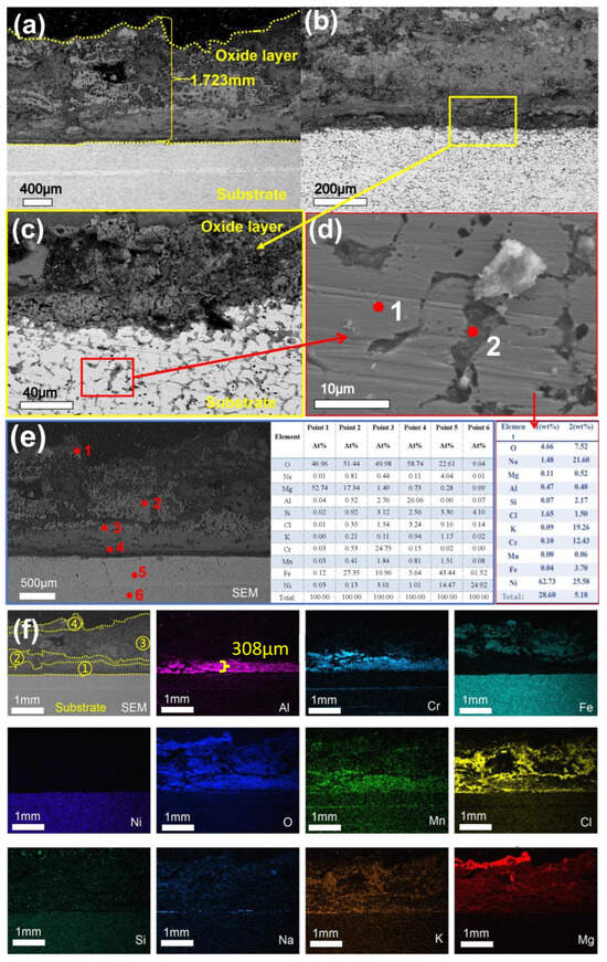
Figure 15.
Cross-sectional SEM/EDS morphology of 310S-2 corroded in chloride salt with Mg for 480 h: (a) Low magnification image; (b) High magnification image; (c) is a high magnification image of the yellow box area in (b); (d) is the high magnification map and point scan of the red box area in (c); (e,f) EDS mapping.
Figure 16 illustrates that the sample experienced further corrosion after 600 h of exposure. As shown in Figure 16a, the thickness of the oxide layer increased to 2.418 mm, with the outermost layer predominantly composed of MgO. Additionally, in Figure 16d, cracks parallel to the substrate surface were observed within the oxide layer, suggesting a lack of density and structural integrity. The direction of the transverse cracks is parallel to the surface of the substrate, indicating that the oxide layer may be more likely to peel off along this direction. The formation of this crack may be related to the different stresses between the oxide layers. According to Figure 16e,f, the layers adjacent to the matrix primarily consist of Al and Cr oxides. Notably, the Al2O3 layer has separated into two distinct layers, with chloride salts embedded between them. The central region of the oxide layer is mainly composed of Fe2O3 and Mn oxides, while elements such as Cl, Na, and K were also detected within the matrix. Analysis of the SEM/EDS images across five time intervals indicates that the overall oxide layer progressively thickened over time. The outer MgO layer was found to be porous, containing voids and cracks. In contrast, the inner oxide layers near the matrix—comprising Al and Cr oxides—exhibited continuous growth and consumption cycles over time. These layers demonstrated relatively good continuity, higher density, and provided effective protection to the underlying material.
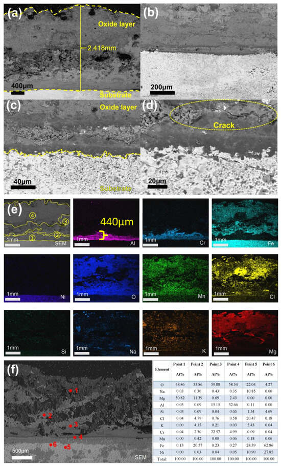
Figure 16.
Cross-sectional SEM/EDS morphology of 310S-2 corroded in chloride salt with Mg for 600 h: (a) Low-magnification image; (b–d) High-magnification image; (e) is the EDS mapping of (a); (f) Point scanning.
By comparing the 310S-1 and 310S-2 samples, neither of them formed a firm Al2O3 film at the initial 120 h. From 240 h on, it could be observed that the Al2O3 layer formed and gradually thickened. Intergranular corrosion was detected in both alloy matrices, yet the overall structural morphology remained largely intact. In the case of Sample 310S-2, Mg powder was intentionally introduced into the molten salt environment. Consequently, MgO and other magnesium-based reaction products became more prominent starting at the 120 h mark, with the layer gradually thickening and acting as a barrier against molten salt infiltration. In contrast, no additional Mg was introduced into the molten salt for sample 310S-1, where the Mg content primarily originated from MgCl2 present in the salt mixture. As a result, early-stage corrosion was more pronounced. Following 480 h of exposure, both the oxidation products and the protective oxide layer reached a state of equilibrium, leading to a stabilization of the corrosion rate. In summary, the addition of Mg as a corrosion inhibitor demonstrates a more effective protective effect against corrosion in high-aluminium 310S stainless steel.
The thickness of the Al2O3 films on the 310S-1 and 310S-2 samples was analyzed, as shown in Figure 17 below. It was observed that the growth of the oxide layer follows a distinct pattern. After 120 h of corrosion, no obvious continuous aluminum oxide layer was detected in either sample. From 240 h onward, the Al2O3 film thickened rapidly, reaching a minimum thickness of approximately 220 µm and 178 µm at 360 h. The film thickness further increased to 410 µm and 308 µm at 480 h. This suggests that the growth of the aluminum oxide film exhibits a wave-like behavior, with the thinnest layer observed at 360 h, followed by renewed thickening. Since the high-aluminum 310S steel underwent pre-oxidation treatment prior to corrosion, the passivation film formed at 800 °C for 2 h in a chloride salt melt environment was completely corroded after 120 h. Subsequently, protection was provided by the MgO, Cr2O3 composite oxide film, allowing the aluminum in the alloy substrate to continue forming and growing the Al2O3 film.
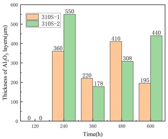
Figure 17.
The thickness of the Al2O3 layers of 310S-1 and 310S-2.
It can be observed from the corrosion rate curve (Figure 2) that at 120 h, the corrosion rates of the 310S-1 and 310S-2 samples reached their peak, indicating the most severe corrosion at this stage. Consequently, the alumina film could no longer maintain continuous stability. As corrosion progressed to 240 h, the corrosion rate began to decrease and subsequently stabilized gradually. Correspondingly, the alumina film had developed to a certain thickness, suggesting that its presence effectively mitigated the corrosion process. During the 240 h–600 h corrosion period, the alumina film continued to grow, providing a stabilizing and protective effect.
4. Discussion
4.1. Corrosion Mechanism of High-Temperature Chloride Salts of Pre-Oxidized High Aluminum 310S
The corrosion mechanism of pre-oxidized high-aluminium 310S in a high-temperature chloride salt environment is shown in Figure 18. According to the mechanism analysis, it mainly involves six key aspects:
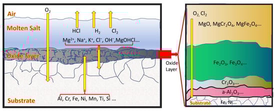
Figure 18.
The corrosion mechanism of pre-oxidized high-aluminium 310S in molten chloride salts.
The first is the decomposition and erosion of chloride salts. At high temperatures, the Cl− produced by the decomposition of chlorides has strong activity and penetrability. It can penetrate into the metal matrix through defects and grain boundaries of the Al2O3 oxide film and react with elements such as Al, Cr, Ni, and Fe to form chlorides (some, such as AlCl3 and FeCl3, are in a gaseous state). Disrupt the continuity and stability of the oxide film and accelerate corrosion (related reactions are shown in Figure 19 and Equations (3) and (4));
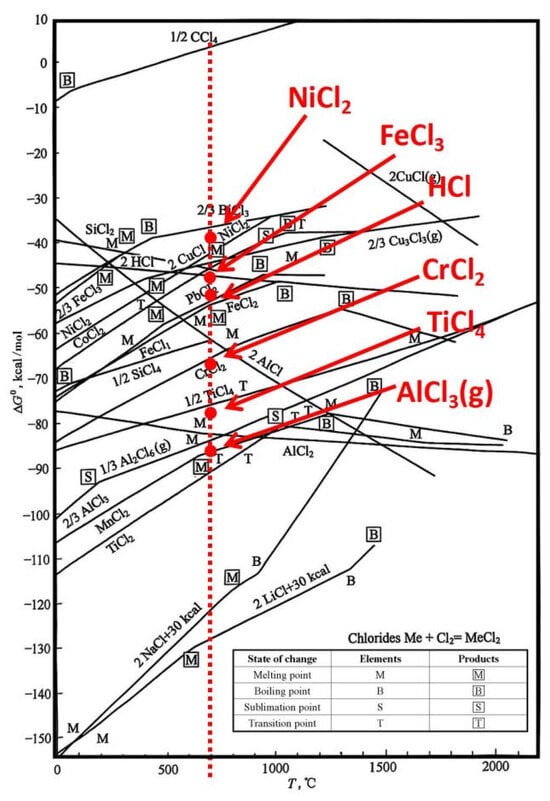
Figure 19.
Metal chlorination reaction diagram [32].
The second, the synergistic effect of oxidation and chlorination, which plays a significant role. Although protective oxide layers—such as Al2O3 formed on the alloy surface at high temperatures and MgO generated from magnesium in molten salts—initially offer some protection, Cl− ions accelerate oxide film growth, resulting in a loose and porous structure. These oxides may react with chlorides to form intermediate compounds like chloroxides. At the same time, gaseous chlorides produced by the reaction between Cr2O3 or Al2O3 and Cl− can volatilize, causing localized rupture of the oxide layer and creating “pathways” for continuous salt penetration. This cycle leads to thickening, cracking, and eventual spalling of the oxide scale, which compromises the alloy’s integrity and performance (see Equation (5)). During the intermediate stage of corrosion, the reaction rate slows due to the formation of multiple oxide layers. Additionally, stable spinel-type phases such as Mg2Si2O6 may develop, as shown in Equation (6).
The third factor is the influence of impurities. Substances such as H2O, H+, O2, MgO, and HCl can generate corrosive gases, including HCl and Cl2, through a series of chemical reactions (as shown in Equations (7)–(12)). These gases circulate via “channels” and react with the alloy until complete corrosion occurs. In the extreme environment at 800 °C without inert gas protection, the Al2O3 passive film plays a critical role in resisting corrosion. Although MgO provides significant initial protection, its protective effect diminishes due to poor stability. During the intermediate and later stages, corrosion resistance primarily depends on the synergistic protection provided by Al2O3 and other oxide films (refer to the oxygen potential diagram in Figure 19 and Figure 20). Figure 19 and Figure 20 are Ellingham diagrams, which serve as core tools in chemical thermodynamics. They “take the reaction Gibbs free energy change (ΔG) as the vertical axis and temperature (T) as the horizontal axis to illustrate the ΔG-T relationships of the formation reactions of compounds (e.g., metal oxides and chlorides)”.
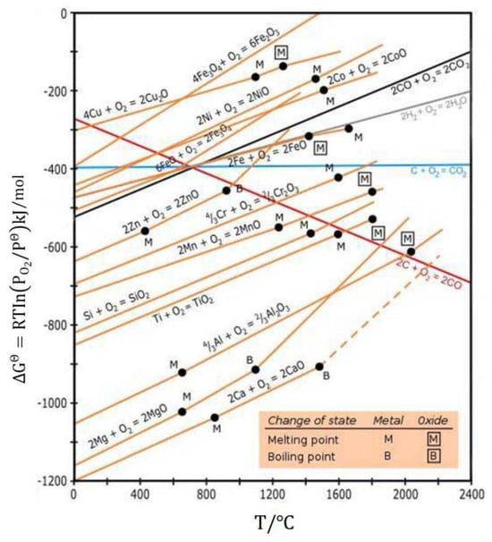
Figure 20.
Ellingham diagram [32].
The fourth is mainly characterized by grain boundary corrosion. Cl− tends to accumulate at high-energy grain boundaries, combining with impurities and defects to accelerate erosion, weakening the grain bonding force, reducing mechanical properties and corrosion resistance, and in severe cases, leading to fracture failure.
The fifth difference lies in the diffusion of alloying elements. Under high-temperature conditions, alloying elements such as Cr, Ni, Fe, and Al undergo diffusion. When the material is exposed to molten salt at 800 °C for an extended period, elements like Cr and Fe diffuse into the oxide film formed on the metal surface, contributing to its structural stability. Concurrently, components present in the molten salt, including Na, K, Mg, and Cl, continuously diffuse into the metal matrix, resulting in the depletion of Cr, Fe, and other critical alloying elements within the matrix. Furthermore, the differing internal stresses among various oxide layers may lead to spallation and the formation of parallel cracks, which are recognized as structural defects (see Figure 16d). These cracks, in combination with micro-channels formed due to intergranular corrosion or pitting within the matrix, provide preferential pathways for the diffusion and migration of alloying elements. Additionally, as temperature increases, the kinetic energy of the alloying elements rises, thereby increasing the diffusion coefficient. If the oxide film contains pores or cracks at this stage, it facilitates the penetration of oxygen, accelerating the overall corrosion rate.
The sixth is the protective effect of the surface oxide film. A continuous and dense oxide film is the key to corrosion resistance, and its performance is affected by the growth rate of Al2O3, phase transition (from γ or θ type to α type, Equation (13)) [33], adhesion during cooling, and the degree of matrix mutual diffusion. Grain refinement and pre-oxidation can improve high-temperature oxidation and corrosion resistance [34,35]. Among them, grain refinement can promote the selective oxidation of Al to form an Al2O3 film. However, this study shows that pre-oxidation at 800 °C for 2 h cannot form a sufficiently thick Al2O3 film in the early stage (there is no complete film at 120 h), and in the initial stage, it relies on the protection of MgO, Cr2O3, etc. After 240 h, Al2O3 gradually grows. At 600 h, the film thickness reached 200–300 μm, indicating that the Al content of the alloy itself can support the severe corrosion for 600 h. At 480 h, the overall oxide film thickness reached its maximum value. After that, the corrosion rate decreased and tended to stabilize, suggesting that 480 h is the corrosion equilibrium node. Therefore, it is necessary to enhance the protection for the first 360 h.
The seventh is that the accumulation of internal stress within the oxide film is the key factor causing the instability of the oxide layer structure in 800 °C chloride-containing molten salt. During the high-temperature oxidation process, the growth of the oxide film generates internal stress. In the early stage of oxidation (film thickness < 100 nm), the compressive stress caused by the epitaxial growth mode is particularly significant when the Pilling-Bedworth (P-B) ratio [35] is greater than 1, as shown in Equation (14). When the internal stress within the oxide film exceeds its own fracture strength or the bond strength between the film and the substrate, the oxide film will experience cracking, spalling, and the formation of holes, providing a direct channel for the invasion of corrosive media. The mismatch in thermal expansion coefficients between the metal or oxide and the volume changes during the oxide film growth process can lead to the generation of internal stress. This not only significantly reduces the mechanical properties of the material but also causes interlayer cracking in the oxide film (cracks are mostly parallel to the substrate surface), weakening its protective performance. The composite oxide layer composed of MgO, Al2O3, Cr2O3, and Fe2O3 observed in the experiment has an uneven internal stress distribution due to the differences in the elemental distribution of each layer, further increasing the risk of oxide film spalling.
According to the Pilling–Bedworth (P-B) principle [35], a necessary condition for the stability of an oxide film is that the ratio of the volume of the metal oxide film formed during oxidation (VMO) to the volume of the consumed metal (VM) must be greater than 1. The calculation is expressed in the following Equation (14):
where M is the relative molecular mass of the metal oxide;
n—the number of metal atoms in the oxide;
A—the relative atomic mass of the metal;
m—the mass of the consumed metal (m = nA);
dM, dMO—the densities of the metal and the oxide film, respectively.
When PB > 1, the oxide film experiences compressive stress and exhibits protective properties, as seen in Al2O3. When PB < 1, the oxide film is subjected to tensile stress, fails to fully cover the metal surface, and tends to form a loose and porous structure, such as MgO. When PB >> 1, the oxide film becomes excessively brittle, cracks easily, and loses its protective capability entirely. The corresponding oxide P-B is shown in Table 4.
Table 4.
P-B Ratio of metal oxide films [32].
4.2. Mechanism of Action of Mg on High-Temperature Chloride Salts of High-Aluminium 310S
Based on the experimental results, in an 800 °C high-temperature chloride salt environment, high-aluminum 310S exhibits superior corrosion resistance compared to conventional 310S, as reported in previous studies. For instance, in reference [17], conventional 310S underwent corrosion in a chloride salt environment at 700 °C for 500 h, resulting in a corrosion rate of 1581 μm/y. This indicates that temperature significantly influences the extent of alloy corrosion. Specifically, when the corrosion temperature increases from 650 °C to 700 °C, the solubility of Cr, Mn, and Fe in the alloy increases markedly. As demonstrated in prior research, a temperature increase of only 50 °C from the initial 650 °C more than doubled the corrosion rates of Incoloy 800H and SS310. The corrosion rate of Incoloy 800H increased from 5.94 mm/y to 14.31 mm/y, while that of SS310 rose from 6.42 mm/y to 12.45 mm/y [16]. In the present study, the material was exposed to an 800 °C chloride salt environment for 480 h, yielding a corrosion rate of only 2645 μm/y—significantly lower than the values reported for conventional 310S under less severe conditions in reference [17].
Mg significantly influences the corrosion behavior of high-aluminum 310S stainless steel in chloride salt environments. When high-aluminum 310S is exposed to a high-temperature chloride salt system containing Mg, the inhibitor rapidly adsorbs onto the alloy surface and forms a protective film that exhibits effective corrosion resistance. Compared to the scenario without the addition of Mg, this protective layer functions as a physical barrier, preventing corrosive Cl− ions from directly contacting the alloy substrate and thereby effectively suppressing the initiation of corrosion. From the perspective of elemental migration, the presence of Mg results in a tightly adhered protective film that hinders the diffusion of corrosive species toward the alloy surface. In contrast, in the absence of Mg corrosion inhibitor, these elements tend to diffuse more readily to the alloy surface, leading to compositional changes and accelerated corrosion. Regarding oxidation behavior, in a chloride salt environment without Mg, oxygen readily reacts with alloying elements such as Fe and Cr, promoting rapid oxidation. However, when Mg corrosion inhibitor is introduced, oxygen preferentially reacts with Mg to form stable Mg-containing oxides or spinels. These compounds inhibit excessive oxidation of the alloy matrix, maintaining the oxidation process in a relatively mild and controlled state. The following reactions occur upon the addition of Mg (Equations (15) and (16)):
M refers to metals such as Cr, Fe, and Ni. Due to the lower oxygen partial pressure of MgO on the oxygen potential diagram compared to other metallic oxides, MgO is more readily formed and exhibits greater thermodynamic stability. Although its structure is less dense and compact than that of Al2O3, it can effectively minimize the erosion caused by molten salts on the underlying substrate, thereby functioning as an outer protective barrier. Additionally, Mg can react with impurities such as MgOHCl present in the salt to produce MgCl2, MgO, and H2 gas as by-products (Equation (17)):
Furthermore, at the corrosion temperature of 800 °C, MgOHCl undergoes thermal decomposition at elevated temperatures to form MgO and release HCl gas (Equation (18)):
The addition of a controlled amount of Mg enables the purification of MgOHCl impurities through the formation of MgO and partial recovery of MgCl2, allowing the external protective mechanism to remain effective until the Mg supply is depleted.
In summary, Mg-based corrosion inhibitors are capable of forming a relatively thick protective layer in high-temperature ternary chloride salt environments. This layer effectively shields the inner oxide layer and substrate, thereby reducing the rate of interaction between the chloride salts and the material surface. The protective shells (in Figure 3 and Figure 4) consist of stable spinel-type structures, including MgO, MgCrO4, MgSiO3, MgAl2O4, and (Mg, Fe)2SiO4, which exhibit excellent thermal stability under high-temperature conditions.
5. Conclusions
This paper investigates the corrosion behavior and underlying mechanisms of high-aluminum 310S stainless steel in a ternary chloride salt environment at 800 °C over a period of 600 h. It also examines the impact of incorporating Mg as a corrosion inhibitor. The key findings are summarized as follows:
- (1)
- High-aluminum 310S exhibits excellent corrosion resistance in molten chloride salts at 800 °C. The corrosion mechanism of 310S containing 2.81 wt.% Al in such environments is characterized by an “oxidation–chlorination” synergistic reaction.
- (2)
- After 120 h of exposure, a protective Al2O3 oxide layer formed on the surface of the pre-oxidized high-aluminum 310S, effectively retarding further corrosion.
- (3)
- The addition of Mg corrosion inhibitor to the molten salt significantly enhanced the corrosion resistance of high-aluminum 310S. This improvement can be attributed to the formation of a thick and continuous protective layer composed of MgO and spinel phases on the alloy surface.
Author Contributions
Conceptualization, Y.W. and P.L.; methodology, Y.W.; software, Y.Z.; validation, M.Z.; formal analysis, F.Z. and H.Y.; investigation, R.L.; resources, Y.W.; data curation, R.L.; writing—original draft preparation, Y.W.; writing—review and editing, P.L.; visualization, P.Y.; supervision, P.L.; project administration, H.Y. and Y.Z.; funding acquisition, P.L. All authors have read and agreed to the published version of the manuscript.
Funding
We gratefully acknowledge the financial supports by Major Science and Technology Projects of Gansu Province (22ZD6GA008 and 23ZDGA008), and by “Research Project on AI-based Operation and Maintenance Management Platform for the Full Lifecycle of Mechanical Products”.
Data Availability Statement
The data presented in this study are available on request from the corresponding author.
Conflicts of Interest
All authors have read and agreed to the published version of the manuscript. The sponsors participate in the specific work of the research, but do not influence the submission of the manuscript.
References
- Sarvghad, M.; Steinberg, T.A.; Will, G. Corrosion of stainless steel 316 in eutectic molten salts for thermal energy storage. Sol. Energy 2018, 172, 198–203. [Google Scholar] [CrossRef]
- Fernández, A.G.; Gomez-Vidal, J.; Oró, E.; Kruizenga, A.; Solé, A.; Cabeza, L.F. Mainstreaming commercial CSP systems: A technology review. Renew. Energy 2019, 140, 152–176. [Google Scholar] [CrossRef]
- Gong, Q.; Shi, H.; Chai, Y.; Yu, R.; Weisenburger, A.; Wang, D.; Bonk, A.; Bauer, T.; Ding, W. Molten chloride salt technology for next-generation CSP plants: Compatibility of Fe-based alloys with purified molten MgCl2-KCl-NaCl salt at 700 °C. Appl. Energy 2022, 324, 119708. [Google Scholar] [CrossRef]
- Sah, S.P.; Tada, E.; Nishikata, A. Corrosion behaviour of austenitic stainless steels in carbonate melt at 923 K under controlled CO2-O2 environment. Corros. Sci. 2018, 133, 310–317. [Google Scholar] [CrossRef]
- Wang, J.W.; Zhang, C.Z.; Li, Z.H.; Zhou, H.X.; He, J.X.; Yu, J.C. Corrosion behavior of nickel-based superalloys in thermal storage medium of molten eutectic NaCl-MgCl2 in atmosphere. Sol. Energy Mater. Sol. Cells 2017, 164, 146–155. [Google Scholar] [CrossRef]
- Fernández, A.G.; Cabeza, L.F. Corrosion evaluation of eutectic chloride molten salt for new generation of CSP plants. Part 2: Materials screening performance. Energy Storage 2020, 29, 101381. [Google Scholar] [CrossRef]
- Kondo, M.; Nagasaka, T.; Sagara, A.; Noda, N.; Muroga, T.; Xu, Q.; Nagura, M.; Suzuki, A.; Terai, T. Metallurgical study on corrosion of austenitic steels in molten salt LiF–BeF2 (Flibe). J. Nucl. Mater. 2009, 386, 685–688. [Google Scholar] [CrossRef]
- Bell, S.; Steinberg, T.; Will, G. Corrosion mechanisms in molten salt thermal energy storage for concentrating solar power. Renew. Sustain. Energy Rev. 2019, 114, 109328. [Google Scholar] [CrossRef]
- Sun, H.; Zhang, P.; Wang, J.Q. Corrosion problems related with molten nitrate salts for heat transfer and thermal storage. Corros. Sci. Prot. Technol. 2017, 29, 567–574. [Google Scholar]
- Ruiz-Cabañas, F.J.; Prieto, C.; Madina, V.; Fernández, A.I.; Cabeza, L.F. Materials selection for thermal energy storage systems in parabolic trough collector solar facilities using high chloride content nitrate salts. Sol. Energy Mater. Sol. Cells 2017, 163, 134–147. [Google Scholar] [CrossRef]
- Williams, D.F.; Toth, L.M.; Clarno, K.T. Assessment of Candidate Molten Salt Coolants for the Advanced High-Temperature Reactor; Oak Ridge National Laboratory: Oak Ridge, TN, USA, 2006. Available online: https://info.ornl.gov/sites/publications/Files/Pub57476.pdf (accessed on 30 August 2025).
- Pint, B.A.; Brese, R.G.; Keiser, J.R. Effect of pressure on supercritical CO2 compatibility of structural alloys at 750 °C. Mater. Corros. 2017, 68, 151–158. [Google Scholar] [CrossRef]
- Luo, J.; Deng, C.K.; Tariq, N.U.H.; Li, N.; Han, R.F.; Liu, H.H.; Wang, J.Q.; Cui, X.Y.; Xiong, T.Y. Corrosion behavior of SS316L in ternary Li2CO3–Na2CO3–K2CO3 eutectic mixture salt for concentrated solar power plants. Sol. Energy Mater. Sol. Cells 2020, 217, 110679. [Google Scholar] [CrossRef]
- Guo, L.; Liu, Q.; Yin, H.; Pan, T.J.; Tang, Z. Excellent corrosion resistance of 316 stainless steel in purified NaCl-MgCl2 eutectic salt at high temperature. Corros. Sci. 2020, 166, 108473. [Google Scholar] [CrossRef]
- Ma, L.; Wu, Y.; Zhang, C.; Lu, Y.; Dong, Y.; Jiao, X. Research on the dynamic corrosion behavior of austenitic stainless steel in quaternary nitrates. ACTA Energiae Solaris Sin. 2023, 44, 497–503. [Google Scholar]
- Gomez-Vidal, J.C.; Tirawat, R. Corrosion of alloys in a chloride molten salt (NaCl-LiCl) for solar thermal technologies. Sol. Energy Mater. Sol. Cells 2016, 157, 234–244. [Google Scholar] [CrossRef]
- Ding, W.; Shi, H.; Xiu, Y.; Bonk, A.; Weisenburger, A.; Jianu, A.; Bauer, T. Hot corrosion behavior of commercial alloys in thermal energy storage material of molten MgCl2/KCl/NaCl under inert atmosphere. Sol. Energy Mater. Sol. Cells 2018, 184, 22–30. [Google Scholar] [CrossRef]
- Fernandez, A.G.; Cabeza, L.F. Corrosion evaluation of eutectic chloride molten salt for new generation of CSP plants. Part 1: Thermal treatment assessment. Energy Storage 2020, 27, 101125. [Google Scholar] [CrossRef]
- Mohan, G.; Venkataraman, M.; Gomez-Vidal, J.; Coventry, J. Assessment of a novel ternary eutectic chloride salt for next generation high-temperature sensible heat storage. Energy Convers. Manag. 2018, 167, 156–164. [Google Scholar] [CrossRef]
- García-Martín, G.; Lasanta, M.; Encinas-Sánchez, V.; de Miguel, M.; Pérez, F. Evaluation of corrosion resistance of A516 steel in a molten nitrate salt mixture using a pilot plant facility for application in CSP plants. Sol. Energy Mater. Sol. Cells 2017, 161, 226–231. [Google Scholar] [CrossRef]
- Wang, J.; Jiang, Y.; Ni, Y.; Wu, A.; Li, J. Investigation on static and dynamic corrosion behaviors of thermal energy transfer and storage system materials by molten salts in concentrating solar power plants. Mater. Corros. 2019, 70, 102–109. [Google Scholar] [CrossRef]
- Sarvghad, M.; Maher, S.D.; Collard, D.; Tassan, M.; Will, G.; Steinberg, T.A. Materials compatibility for the next generation of concentrated solar power plants. Energy Storage Mater. 2018, 14, 179–198. [Google Scholar] [CrossRef]
- Chen, H.-Z.; Li, B.-R.; Wen, B.; Ye, Q.; Zhang, N.-Q. Corrosion behaviors of iron-chromium-aluminium steel near the melting point of various eutectic salts. Sol. Energy Mater. Sol. Cells 2020, 210, 110510. [Google Scholar] [CrossRef]
- Bhuyan, P.; Pradhan, S.; Mitra, R.; Mandal, S. Evaluating the efficiency of grain boundary serrations in attenuating high-temperature hot corrosion degradation in Alloy 617. Corros. Sci. 2019, 149, 164–177. [Google Scholar] [CrossRef]
- Fernández, A.G.; Pineda, F.; Walczak, M.; Cabeza, L.F. Corrosion evaluation of alumina-forming alloys in carbonate molten salt for CSP plants. Renew. Energy 2019, 140, 227–233. [Google Scholar] [CrossRef]
- Wei, Y.; Cao, J.; Yu, H.; Sheng, J.; La, P. Effect of Mg addition on molten chloride salt corrosion tance of 310S stainless steel with aluminum. Metals 2024, 14, 1109. [Google Scholar] [CrossRef]
- Pradhan, S.K.; Jena, P.S.M.; Chaithanya, P.V.S.; Singh, R. Enhancement of molten salt corrosion resistance of Ni-based superalloy through adding inhibitor. Trans. Indian Inst. Met. 2024, 77, 1323–1328. [Google Scholar] [CrossRef]
- Hu, X.; Ye, S.; Qi, M.; Yang, P.; Zhang, Y.; Wu, W.; Lu, X. Microstructure and mechanical properties evolution of 310S and GH3536 in hydrogen metallurgy service. Int. J. Hydrogen Energy 2025, 107, 426–437. [Google Scholar] [CrossRef]
- Yu, H.; Zhang, Y.; Jin, J. Mechanism of Al content on the microstructure and properties of hot-rolled heat-resistant steel. J. Iron Steel Res. Int. 2024, 36, 348–358. [Google Scholar]
- Ding, W.; Shi, H.; Jianu, A.; Xiu, Y.; Bonk, A.; Weisenburger, A.; Bauer, T. Molten chloride salts for next generation concentrated solar power plants: Mitigation strategies against corrosion of structural materials. Sol. Energy Mater. Sol. Cells 2019, 193, 298–313. [Google Scholar] [CrossRef]
- ASTM G1-03-E; Standard Practice for Preparing, Cleaning, and Evaluating Corrosion Test Specimens. ASTM: West Conshohocken, PA, USA, 1999; pp. 1–8.
- Li, T. High-Temperature Oxidation and Thermal Corrosion; Chemical Industry Press: Beijing, China, 2003; pp. 208–215. [Google Scholar]
- Yin, Z.; Chen, W.; Li, J. The influence of F− on phase transformation of Alumina and microstructure of α-Al2O3. Bull. Chin. Ceram. Soc. 2007, 26, 640–644. [Google Scholar]
- Fernandez, A.G.; Perez, F.J. Improvement of the corrosion properties in ternary molten nitrate salts for direct energy storage in CSP plants. Sol. Energy 2016, 134, 468–478. [Google Scholar] [CrossRef]
- Zhang, S. Corrosion and Protection of Metallic Materials; Beijing Institute of Technology Press: Beijing, China, 2023; pp. 10–21. [Google Scholar]
Disclaimer/Publisher’s Note: The statements, opinions and data contained in all publications are solely those of the individual author(s) and contributor(s) and not of MDPI and/or the editor(s). MDPI and/or the editor(s) disclaim responsibility for any injury to people or property resulting from any ideas, methods, instructions or products referred to in the content. |
© 2025 by the authors. Licensee MDPI, Basel, Switzerland. This article is an open access article distributed under the terms and conditions of the Creative Commons Attribution (CC BY) license (https://creativecommons.org/licenses/by/4.0/).