Article

Study of the Tribological Properties of Self-Fluxing Nickel-Based Coatings Obtained by Gas-Flame Spraying

by
Dastan Buitkenov
,
Nurmakhanbet Raisov
*,
Temirlan Alimbekuly
and
Balym Alibekova
Research Center “Surface Engineering and Tribology”, Sarsen Amanzholov East Kazakhstan University, Ust-Kamenogorsk 070000, Kazakhstan
*
Author to whom correspondence should be addressed.
Crystals 2025, 15(10), 862; https://doi.org/10.3390/cryst15100862
Submission received: 4 August 2025 / Revised: 29 September 2025 / Accepted: 30 September 2025 / Published: 30 September 2025
(This article belongs to the Section Inorganic Crystalline Materials)

Abstract

Self-fluxing Ni-based coatings (NiCrFeBSiC) were deposited through gas-flame spraying and evaluated in three conditions: as-sprayed, flame-remelted, and furnace-heat-treated (1025 °C/5 min). Phase analysis (XRD) revealed FeNi3 together with strengthening carbides/borides (e.g., Cr7C3, Fe23(C,B)6); post-treatments increased lattice order. Cross-sectional image analysis showed progressive densification (thickness ~805 → 625 → 597 µm) and a drop in porosity from 7.866% to 3.024% to 1.767%. Surface roughness decreased from Ra = 31.860 to 14.915 to 13.388 µm. Near-surface microhardness rose from 528.7 ± 2.3 to 771.6 ± 4.6 to 922.4 ± 5.7 HV, while adhesion strength (ASTM C633) improved from 18 to 27 to 34 MPa. Wettability followed the densification trend, with the contact angle increasing from 53.152° to 79.875° to 89.603°. Under dry ball-on-disk sliding against 100Cr6, the friction coefficient decreased and stabilized (0.648 ± 0.070 → 0.173 ± 0.050 → 0.138 ± 0.003), and the counterbody wear-scar area shrank by ~95.6% (0.889 → 0.479 → 0.0395 mm2). Wear-track morphology evolved from abrasive micro-cutting (as-sprayed) to reduced ploughing (flame-remelted) and a polishing-like regime with a thin tribo-film (furnace). Potentiodynamic tests indicated the lowest corrosion rate after furnace treatment (CR ≈ 0.005678 mm·year−1). Overall, furnace heat treatment provided the best structure–property balance (lowest porosity and Ra, highest HV and adhesion, lowest and most stable μ, and superior corrosion resistance) and is recommended to extend the service life of NiCrFeBSiC coatings under dry sliding.

1. Introduction

Modern mechanical engineering often faces the need to develop new structural materials with high-performance properties for operation in harsh technological conditions—under high friction, exposure to various external environments, and thermal loads. These operating conditions often lead to wear and tear on equipment parts, which in turn lead to frequent repairs, replacement of worn parts, and an increase in the cost of manufactured products, which, accordingly, leads to economic losses [1,2,3].
However, despite this, manufacturing parts entirely from expensive wear-resistant materials leads to a sharp increase in cost and difficulties in processing parts. The solution to this problem is to apply wear-resistant coatings to the surface of the part, as well as to restore worn parts, thereby significantly increasing their service life [1].
The restoration of shafts and rotors remains a pressing issue due to erosion, cavitation, corrosion and abrasive wear in the energy and hydropower industries. Traditional repair technologies include argon arc/surfacing welding, spraying and machining with replacement of parts when repair is not feasible. The use of coatings preserves the structural properties of the base, reduces replacement costs and shortens equipment downtime. Coatings are used as an alternative or supplement to weld overlay in the repair of hydro turbine blades and other shafts where it is necessary to reduce metal exchange with the base and preserve the geometry of the part [4,5,6]. Wear damage to shafts is often repaired by overlay welding or coating; self-fluxing nickel systems (Ni-Cr-B-Si, Ni-Cr-B-Si-C, Ni-Cr-Fe-B-Si-C, Fe-Cr-Mo-C-B, Fe-Cr-Mo-Si-B modifications) offer an economical alternative with high wear resistance and the possibility of heat treatment. Fe-containing systems are an economical alternative, demonstrating increased hardness and wear resistance, but are inferior to Ni coatings in terms of corrosion and thermal stability [7,8]. Ni series coatings are characterised by high corrosion resistance and stability at temperatures up to 900 °C. Self-fluxing nickel alloys are usually widely modified with ceramic additives (WC, TiB2, TiCrC, etc.); such compositions are available in the form of powders for spraying, welding wire or pastes for laser cladding. NiCrBSi forms a Ni–Cr matrix with dispersed boride/carbide phases that provide hardness and wear resistance; the addition of WC/Co or TiB2 increases hardness and wear resistance but may increase roughness and the friction coefficient [9,10,11,12].
Gas-thermal (including plasma) coatings based on Ni-Cr-Fe-B-Si-C are used to increase the wear resistance of machine parts. NiCrFeBSiC is actively used to increase the wear resistance of parts operating under conditions of intense friction, such as elements of coal-fired boilers, heat exchange equipment, turbines, tools, extruders, plungers, rolling mill rolls, and agricultural machinery. Among the various Ni-based alloy coatings, NiCrBSi is a self-fluxing alloy due to the presence of B and Si, which enhance the metal’s ability to self-flux, making it favorable for coating deposition, and form hard phases with Ni, such as Ni3B [13,14,15]. In addition, chromium can further enhance its corrosion resistance and wear resistance through the precipitation of hard particles. NiCrBSi alloys with good glass-forming ability provide even higher mechanical strength, excellent corrosion and wear resistance, low hardness, and good elasticity, which makes them widely used in engines, piston rods, and boilers due to their high resistance to wear and corrosion [16,17,18].
The technologies for applying protective coatings are undoubtedly one of the fundamental directions in the development of materials. A distinct group of technologies, referred to as “thermal spraying”, relies on melting and subsequently depositing solid materials onto a pre-prepared surface in the form of a dispersed stream. The broad spectrum of materials employed enables the use of such technologies across diverse industrial sectors. At present, NiCrBSi composite coatings can be rapidly deposited using thermal spraying methods, including atmospheric plasma spraying (APS), arc spraying (AS), flame spraying (FS), and high-velocity oxy-fuel spraying (HVOF) [19,20,21,22]. In this study, flame spraying was selected as the primary technology for self-fluxing coatings of the Ni–Cr–Fe–B–Si–C family due to its technological rationale and practical applicability. Unlike HVOF and APS, the flame spraying process enables the “spraying → fusing” sequence to be carried out within a single unit and with the same flame, eliminating the need for part transfer or equipment adjustment. The mobility of the equipment and its modest infrastructure requirements enable field and large-scale repairs—such as those of shafts, rollers, and bearing seats—under conditions where the use of stationary chambers is impractical or unfeasible.
This study focuses on coatings produced through the flame remelting technique. In cases where wear and corrosion resistance are needed at low to moderate temperatures, nickel-based self-fluxing alloys are widely employed [23]. The formation of protective coatings with alloys of this type is generally performed in two steps: deposition (spraying) of the feedstock material (most often in powder form), followed by subsequent or simultaneous remelting of the deposited layer. Remelting enhances the density of the sprayed layer by eliminating the pores and voids that inevitably form during deposition while also establishing a strong metallurgical bond between the coating and the substrate. Under optimal remelting parameters and an appropriate balance of alloying elements, it is possible to obtain uniform coatings with minimal defects and the desired functional properties. Processes such as deoxidation, degassing, nucleation, and grain growth occur during remelting, and the final structure of the coatings, along with their properties, is largely determined by the efficiency of these processes. As the remelting of coatings is similar to the melting of bulk alloys, certain structural control methods known and applied in metallurgy can likewise be effectively employed in the technology of remelted coatings [24].
To ensure the required tribotechnical properties of melted coatings based on Ni-Cr-Fe-B-Si-C, the heat treatment process must be carried out strictly at a specific temperature (in the range of 1000–1373 K) since these materials are eutectic alloys and are highly sensitive to thermal exposure parameters [25,26]. Melting can be carried out using various methods, including spraying followed by melting with a gas flame, in a furnace, and using laser melting.
In articles [13,14,15,16,17,18,19,20,21,22,23,24,25,26], the properties and characteristics, as well as phase transformations during flame heating of self-fluxing NiCrBSiC coatings, were well studied. Most prior studies focus on the wear mechanisms of the coated specimen only, whereas self-fluxing NiCr(B)Si(C) coatings are typically used to repair shafts operating against a mating component. Wear-resistant coatings based on nickel-containing self-fluxing alloys (Ni-Cr-Fe-B-Si-C) are widely used to restore and protect parts operating under conditions of friction and corrosion. Despite a significant number of studies devoted to the investigation of phase transformations, structure and mechanical properties of such coatings after surfacing and heat treatment, most studies are limited to analysing the behaviour of the coating itself. However, real operating conditions involve the coating working in conjunction with a mating surface, where wear and damage develop simultaneously on both mating surfaces. The insufficient study of the patterns of joint wear of the coating and the counterbody material significantly complicates the prediction of the durability of restored parts and the selection of optimal operating modes for them.
The novelty of the present research lies in evaluating NiCrFeBSiC coatings within a two-element tribosystem (“coating–counterbody”), which better reflects actual service conditions. Unlike earlier studies that primarily analyzed coating degradation, we investigate both interacting surfaces under identical dry ball-on-disk conditions (100Cr6 steel ball). This approach allows us to reveal not only coating damage mechanisms but also counterbody wear phenomena, including material transfer, third-body formation, and transitions between micro-cutting, micro-ploughing, and oxidative glaze. To the best of our knowledge, such a combined tribological assessment of both elements of the pair has not yet been systematically reported for self-fluxing Ni-based coatings.

2. Materials and Methods

AISI 1045 structural carbon steel was selected as the substrate material. This steel is often used in industry for the manufacture of shaft gears, crankshafts and camshafts, gears, spindles, tyres, cylinders, cams and other normalised, improved and surface heat-treated parts that require increased strength. According to ASTM A108, [27] AISI 1045 steel has the following composition (Table 1).
A carbon steel bar made of AISI 1045 steel with a diameter of 50 mm was cut into discs with a thickness of 5 mm. The surface was mechanically treated through grinding with sandpaper with a grain size of up to P600. To improve the adhesion of the applied coating, the surface of the discs was additionally treated through abrasive blasting using electrocorundum (Al2O3) with a particle size of 40 μm. After sandblasting, the average roughness profile Ra was 1.419 μm (arithmetic mean value for 3 samples). After sandblasting, the abrasive and dust residues were removed by blowing with compressed air. In order to remove organic and inorganic contaminants (oils, oxide films), the samples were cleaned in an ultrasonic bath using technical-grade ethanol. The duration of ultrasonic cleaning was 10 min at a frequency of 40 kHz and a solution temperature not exceeding 35 °C. Before applying the coating, the samples were preheated to temperatures of 200–250 °C using gas flame heating to improve adhesion to the substrate. The surface temperature was controlled using a RoHS DT8016E (Shenzhen Yibai Network Technology Co., Ltd., Shenzhen, China) infrared pyrometer with a measurement range of −50 °C to 1600 °C and an accuracy of ±2 °C. Morphology of self-fluxing NiCrFeBSiC powder in Figure 1.
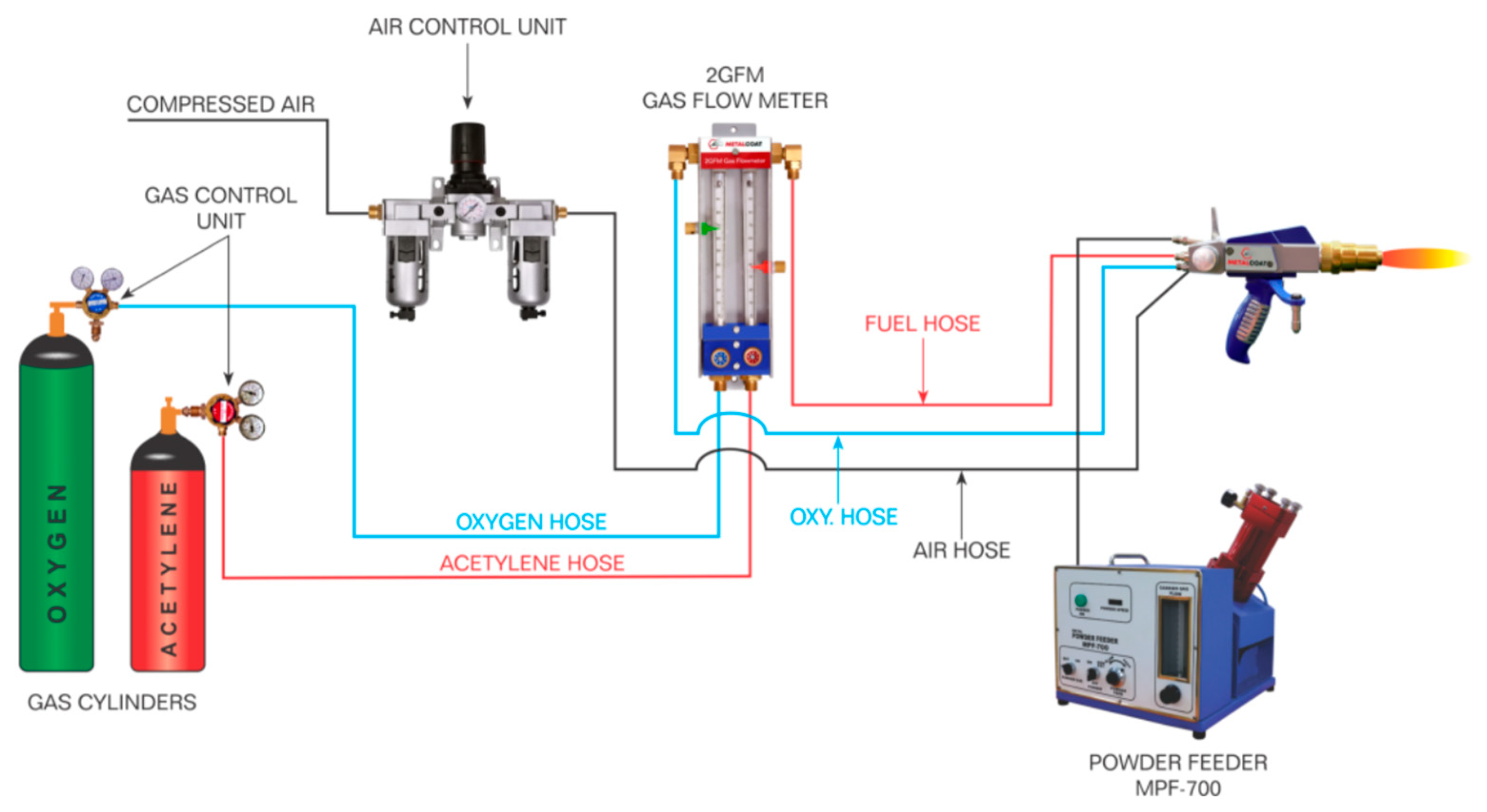
A Metal Coat gas-flame spraying unit was used to apply the coatings, employing a 6PM-II powder gun (Metal Coat, Jodhpur (Raj.), India) and an MPF700 powder dispenser (Metal Coat, Jodhpur (Raj.), India). A general view of the equipment and a diagram of the gun are shown in Figure 2. The principle of operation of this equipment is to melt particles by burning a gas mixture consisting of acetylene and oxygen. Compressed air is used to transport the powders and cool the barrel. Air from the compressor passes through a filter built into the outlet pressure regulator to prevent contamination of the powders with motor oil particles. The gas mixture supply is controlled and regulated by gas flow meters and a compressed air control unit. A powder supply adjustment function is also provided to reduce consumption. The particle flow rate and flame temperature were measured using a Tecnar Accuraspray 4.0 high-speed camera (Tecnar Automation Ltd.: Saint-Bruno-de-Montarville, QC, Canada).
The spraying parameters were selected so that the porosity of the coatings did not exceed 10% (ISO/TR 26946:2011) [28]. The spraying mode is shown in Table 2.
The preheating of the AISI 1045 steel base was carried out using the flame gas method to a low tempering temperature of 200–250 °C. After preheating, the microhardness of AISI 1045 steel was determined using the Vickers method at 15 different surface points. Before heating, the average microhardness of AISI 1045 steel was 196.7 ± 5.3 HV0.3, while after heating, it was 298.6 ± 5.7 HV0.3. This pretreatment was carried out immediately before spraying to improve the adhesion of the substrate to the sprayed material. Heating helps to improve the microstructure of the coating, promotes more uniform spraying of the material and reduces internal stress in the coating.
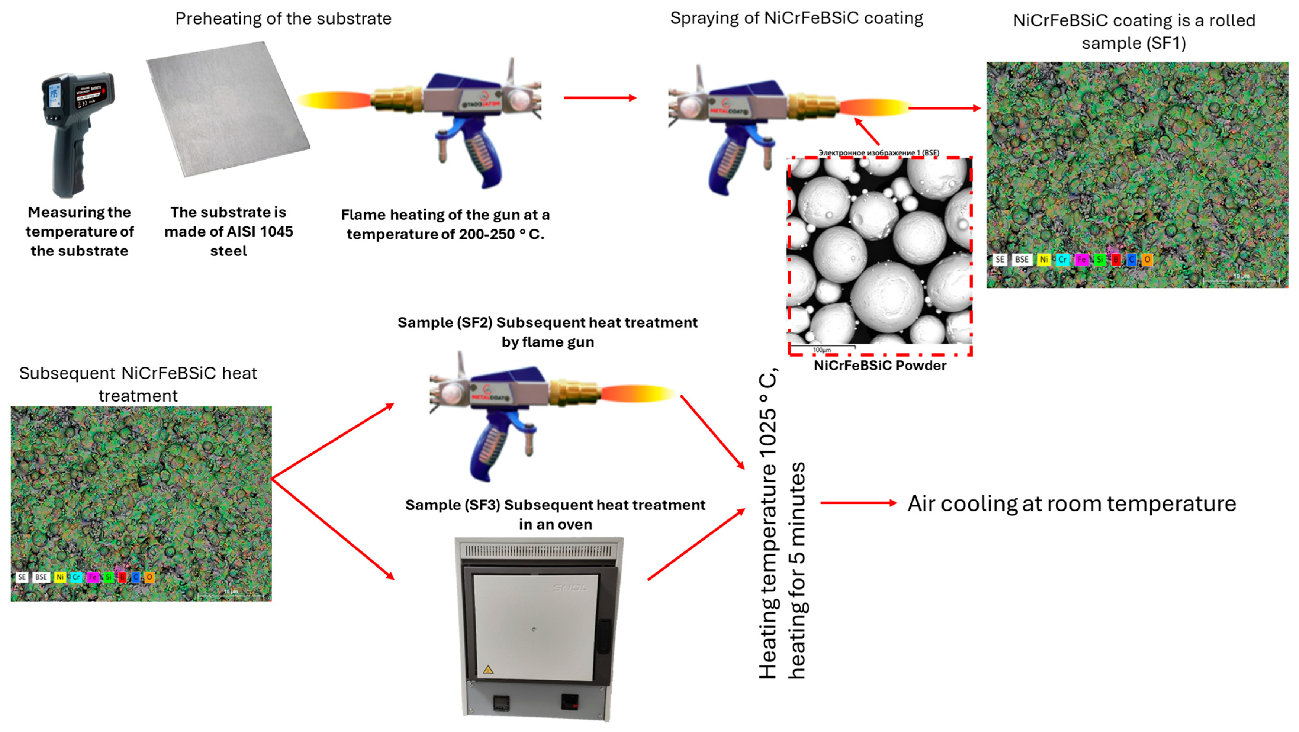
The heat treatment of the coatings was carried out using two methods at a temperature of 1025 °C for 5 min: (1) gas flame heating; (2) heating in a furnace (Figure 3). The morphology of the coatings was studied using a SEM 3200 scanning electron microscope (KYKY Technology Co., Ltd., Beijing, China), equipped with an attachment for an electron probe for local microanalysis: a Brooker energy-dispersive spectrometer (EDS).
X-ray diffraction (XRD) analysis of the original powder and coatings was carried out on a PANalytical X’PERT PRO diffractometer (PANalytical, Almelo, The Netherlands) using CuKα radiation. X-ray diffraction was carried out using the following parameters: the angle ranged from 10 to 90° with a step of 0.02° and an exposure of 0.5 s [29].
Tribological tests of the coatings using the “ball-on-disk” scheme. A 100Cr6 steel ball with a diameter of 6 mm was used as a counterbody, the load was 10 N, the rotation speed was 5 cm/s, the radius of curvature was 2 mm, and the friction path length was 200 m. The specific wear rate (W, mm3/N·m) was calculated based on the cross-sectional area of the worn track according to the following (Equation (1)).
w = A ( 2 π r N ) F L
A—cross-sectional area of the worn track, mm2;
r—track radius, mm;
N—number of revolutions;
F—load, N;
L—friction path, m.
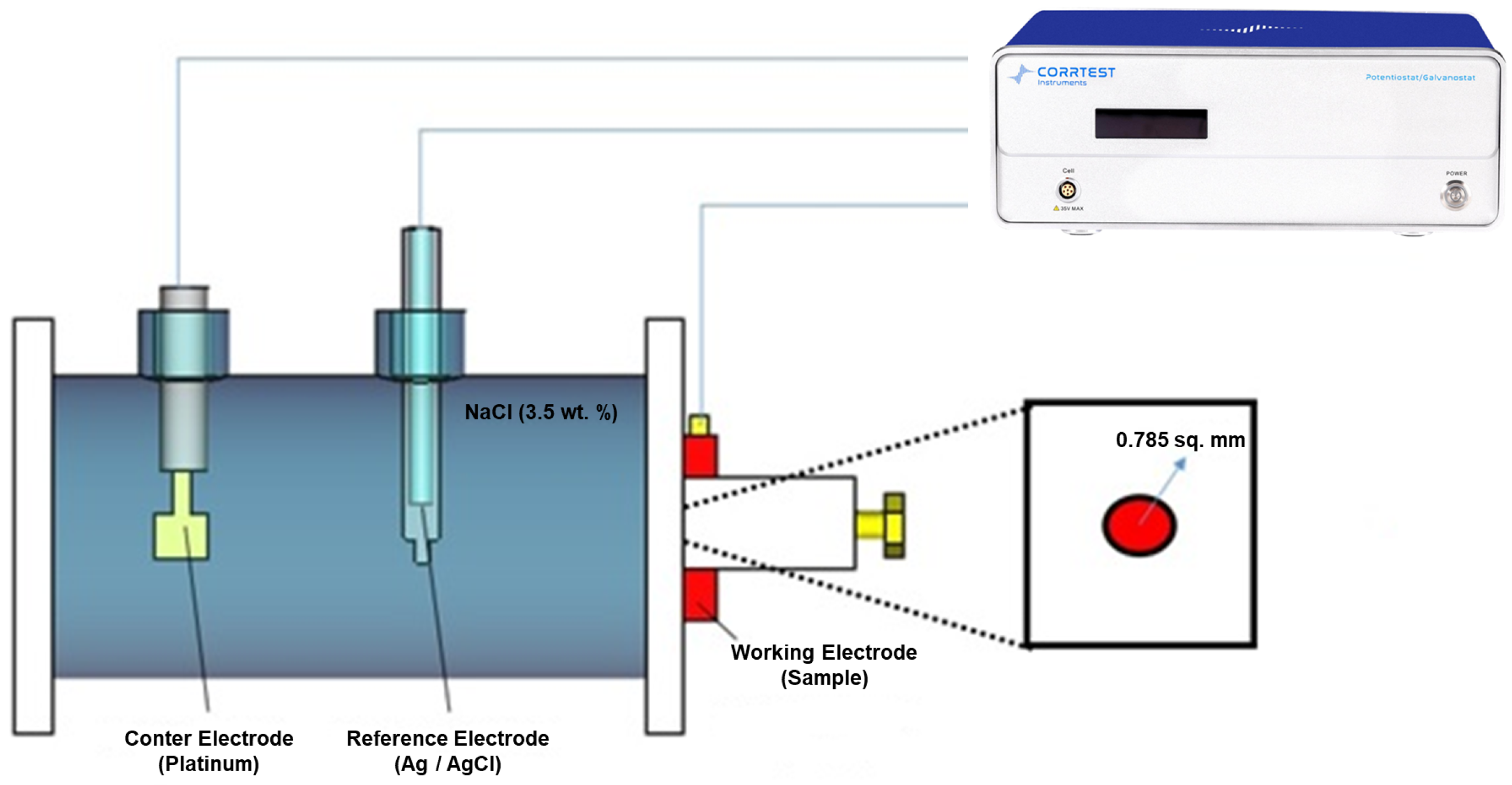
The potentiodynamic curves were recorded using a CorrTest CS310 potentiostat (CorrTest Instruments Corp., Ltd., Wuhan, China) with a three-electrode cell, as shown in Figure 4. The scanning rate was 0.5 mV/s with a scanning range from −0.8 V to +0.8 V. A 3.5% HCl solution was used as an electrolyte. The working electrode was a platinum mesh; saturated silver chloride electrodes were used as an auxiliary electrode and a reference electrode. The results obtained from the current and potential measurements were calculated CorrTest CS310 potentiostat software version 6.3.1128.1, which were used to plot the polarization curve, which generally provides information on the corrosion potential, corrosion current and passivation behavior [30,31].
Adhesion strength tests were performed according to ASTM C633.15080 [32] on a WDW-100 kN (Jinan Testing Equipment IE Corporation, Jinan, China) tensile testing machine using a self-leveling load module direction. Samples with a diameter of 25.4 mm and a thickness of 7 mm were prepared for adhesion testing. Before spraying, the samples were sandblasted and cleaned in an ultrasonic bath in alcohol. The stretching speed was 0.020 mm/s. The maximum load at the point of coating detachment was recorded and divided by the bonded surface area, which yielded the adhesion strength values reported in the table. Each value represents the average of three independent tests (Equation (2)).
= F max A
∂—adhesion strength of the coating, MPa;
Fmax—maximum load at coating detachment, N;
A—bonded surface area of the specimen, mm2.
The wettability of the surface was evaluated using the sessile drop method, in accordance with ISO 19403-2:2024—‘Paints and varnishes—Wettability—Part 2: Determination of the surface free energy of solid surfaces by measuring the contact angle’ [33]. The tests were conducted on samples that were pre-cleaned of contaminants using ultrasonic cleaning and solvents. Distilled water was used as the test liquid, which was applied to the surface using a pipette. The contact angle between the drop and the surface was measured using a goniometer, and drop images were captured with a camera equipped with an image analysis system. The contact angle was measured immediately after placing the drop, and three repeated measurements were taken for each surface to ensure accuracy. The obtained data allowed for the determination of the material’s hydrophilicity or hydrophobicity based on the contact angle value.
The hardness of the samples was measured using the Vickers method in accordance with the international standard ISO 6507-1:2018 [34]. A diamond indenter with a 136° apex angle was applied to the material surface with a specified load. After the load was applied, an indentation was left on the surface of the sample, which was measured using a microscope. The two diagonals of the indentation were measured, and the average diagonal length was calculated based on these measurements.

3. Results

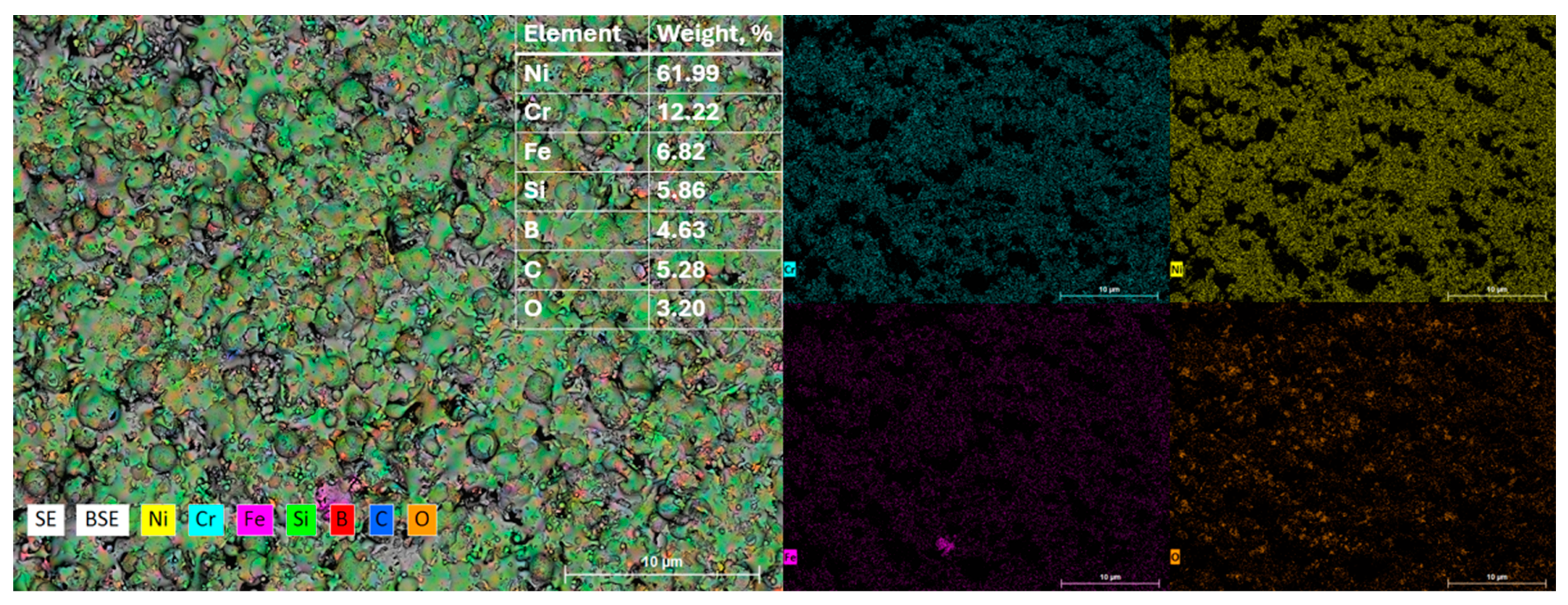
To study the microstructure and elemental composition of the coating based on NiCrFeBSiC, energy-dispersive X-ray spectral analysis (EDS) was carried out as part of scanning electron microscopy (SEM). The results are presented in Figure 5 in the form of element distribution maps and a summary table of mass fractions [35,36,37,38].
According to the quantitative analysis, the powder consists predominantly of nickel (61.99 wt.%), which forms the basis of the alloy. A significant proportion is occupied by chromium (12.22 wt.%), which provides corrosion resistance and high-temperature strength. The presence of silicon (5.86 wt.%), boron (4.63 wt.%), and carbon (5.28 wt.%) imparts self-fluxing properties to the material, promoting the formation of a dense coating during flame spraying. The minor oxygen content (3.20 wt.%) is associated with partial surface oxidation of the particles.
Elemental mapping confirms their uniform distribution within the powder structure. Nickel, chromium, and silicon are distributed the most uniformly, indicating the homogeneity of the initial material. The close spatial association of boron and silicon indicates the possibility of forming eutectic compounds, which ensure fusibility and good spreading of the coating.
The samples treated through flame heating using the SF2 gun and those subjected to furnace heat treatment (SF3) were compared with the reference samples that were not heat-treated (SF1), as well as with the initial NiCrFeBSiC powder (Powder). The X-ray diffraction patterns of the above-described samples are shown in Figure 6. The most intense peak may correspond to the FeNi3 phase. The Ni2B, FeSi2, and Fe23(C,B)6 phases were also identified with high probability. These two phases are most frequently mentioned in the relevant studies [34,35,36,37]. Within the framework of the study of X-ray spectra of the Ni-Cr-Fe-B-Si-C powder and the remelted layer, comparative analyses of the diffraction patterns were carried out, which, while sharing common features, also demonstrated certain differences. Despite the similarity of the diffraction patterns of the powder and the coating, it was found that the Ni peaks in the remelted layer were slightly shifted to the left compared to the powder state, indicating an increase in the lattice parameter of the Ni solid solution in the remelted layer. The calculated lattice parameters of the Ni solid solution for the clad layer and the initial powder are 3.57 Å and 3.55 Å, respectively. This increase in the lattice parameter can be explained by the dissolution of Fe in Ni occurring during the laser treatment of the coating, which leads to a dilution of the initial composition.
The analysis of the peaks in the diffraction pattern showed the following:
-
The decrease in the intensity of diffraction peaks during spraying indicates that the coating obtained using the spraying method became more amorphous compared to the initial powder. This may occur due to limited cooling and rapid formation of the coating, during which large crystalline structures do not have time to form. This may also indicate the presence of micropores, which reduce the amount of crystalline phases observable in X-ray diffraction.
-
The increase in intensity after flame remelting compared to the sprayed layer may indicate the onset of crystallization and structural stabilization of the material. The flame remelting process leads to local heating of the coating, which promotes a more complete formation of crystalline phases. However, the intensity is still lower than that of the initial powder, indicating the presence of a considerable amount of amorphous or microcrystalline regions.
-
A significant increase in intensity after furnace heating indicates a more complete crystalline transformation of the material. At the high temperatures that can be reached in the furnace, the formation of a more stable and ordered crystalline structure is promoted. The increase in peak diffraction intensity at this stage may indicate crystal growth and an enhancement in lattice ordering. This is particularly noticeable with respect to the Ni peaks, which are broadened in the case of the coating. The broadening of the peaks may be associated with distortion of the crystalline structure caused by the rapid cooling of the material during the laser treatment, which is characteristic of thermally treated coatings, as demonstrated in the work of Li et al. (2001) [23].
This phase behavior is consistent with data from the literature, which indicate that heat treatment promotes the formation of stable strengthening phases in Ni-based coatings [11,39,40,41,42].
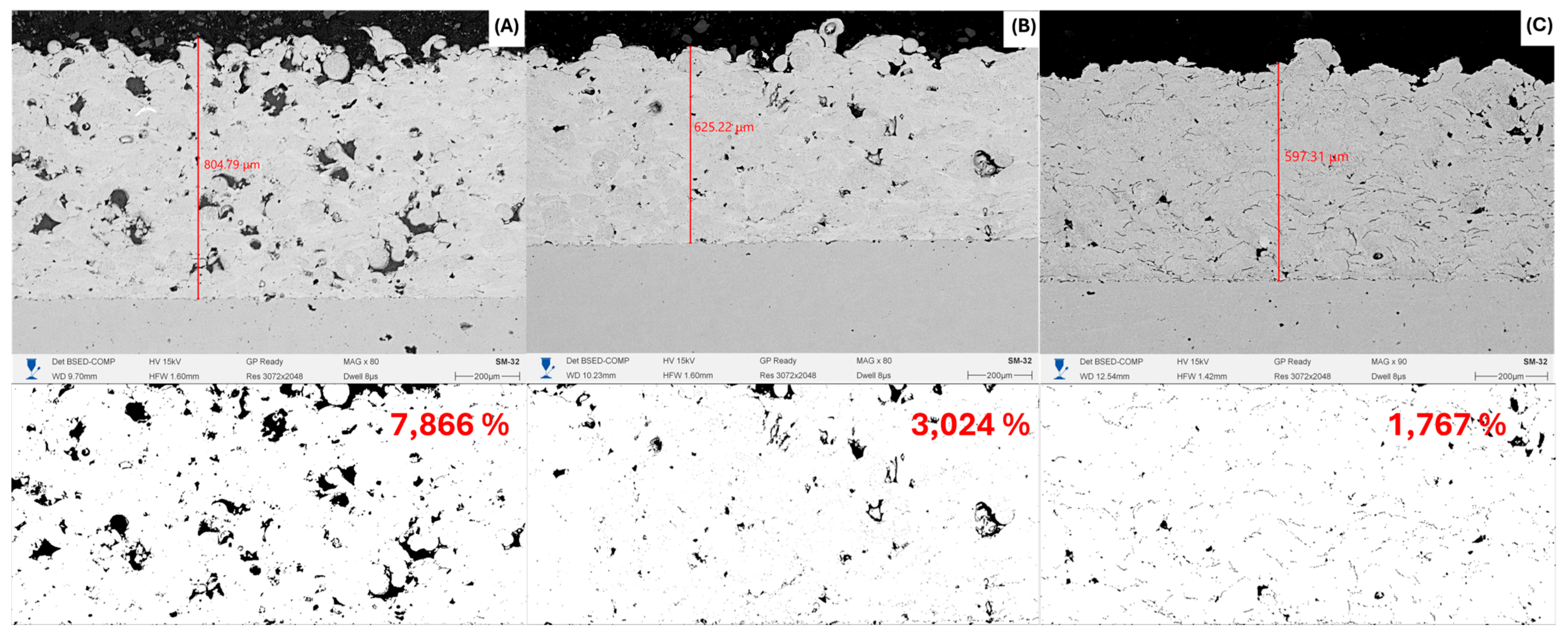
Figure 7 clearly shows that subsequent heat treatment significantly reduces the coating thickness, as well as the number and size of pores. This trend occurs due to better fusion of particles and filling of pores with molten material [42,43,44]. The highest porosity is recorded in sample (SF1), which did not undergo additional heat treatment. A high porosity value indicates the presence of a large number of unmelted particles. In the coating (SF2), which underwent short-term flame heating, a significant decrease in porosity by almost 2.5 times is observed compared to the untreated coating. This indicates a partial compaction of the structure of the near-surface layers of the coatings and the self-fluxing process under the influence of temperature (Figure 7B). Minimum porosity is observed in sample (SF3), heated in a furnace. The furnace provides more uniform and long-term heating, which contributes to active self-fluxing and improved adhesion between the coating particles. As a result, the structure becomes denser and more homogeneous (Figure 7C) [20,33,45].
Figure 7 presents cross-sectional SEM micrographs (upper row) showing the coating thickness after different heat treatment regimes and the corresponding binarized images (lower row) used for porosity evaluation. The as-sprayed coating (Figure 7A) has a thickness of ~805 µm with a porosity level of 7.866%, while after gas-flame heating (Figure 7B) and furnace treatment (Figure 7C), the thickness slightly decreases (625 µm and 597 µm, respectively) due to densification, and the porosity reduces significantly to 3.024% and 1.767%. These quantitative results confirm that heat treatment promotes compaction of the coating structure, closure of pores, and improvement of microstructural homogeneity.
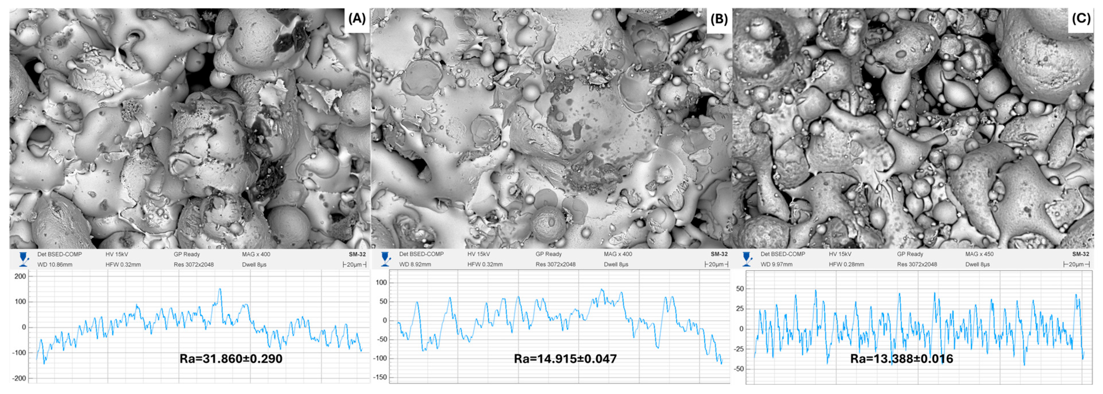
A decrease in the Ra parameter from 31.860 μm (without treatment) to 13.388 μm (furnace treatment) (Table 3) demonstrates a clear trend towards an improvement in the quality of the coating surface with the use of heat treatment (Figure 8). SEM micrographs confirm that heat treatment promotes compaction of the structure, reduction in porosity and leveling of the surface. The obtained data indicates a significant influence of heat treatment on the morphological and tribological properties of the coatings and also emphasizes the advantage of uniform heating in a furnace compared to gas-flame heating.
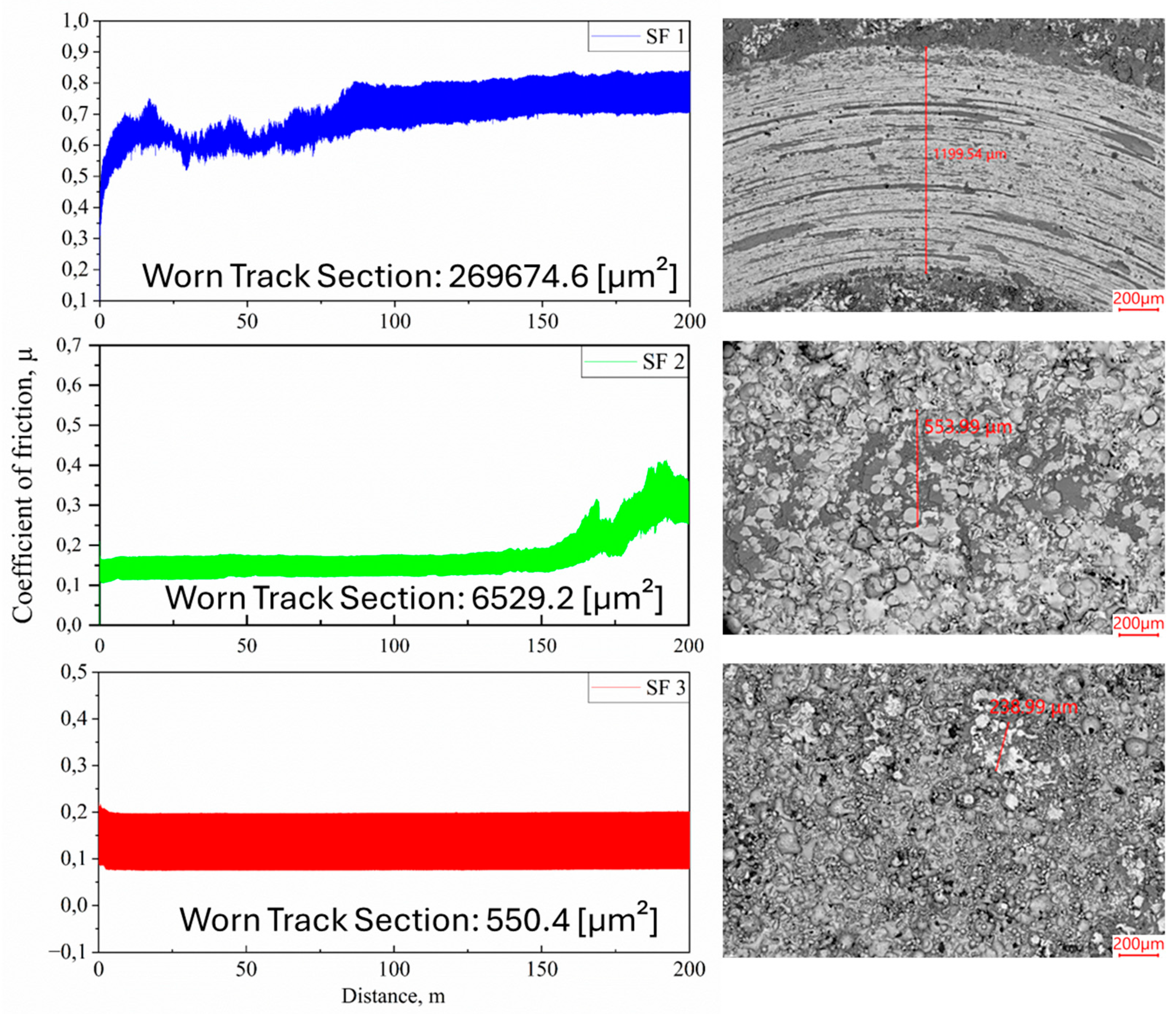
Tribological tests were conducted to test the wear resistance of the coatings. The results are shown in Figure 9. According to the results of tribological tests with dry friction, it was found that subsequent heat treatment reduces the friction coefficient; thus, thermal gas-flame heating and furnace treatment reduced the friction coefficient by 6 times on average for both types of treatment.
The cross-sectional area values (A) were determined from profilometric measurements (see Figure 9). Based on these, the calculated wear rates for each sample are summarized below (Table 4):
The tribological performance of the investigated samples was evaluated based on the evolution of the coefficient of friction (COF), the cross-sectional area of the worn track, and the calculated specific wear rate (Table 4). Figure 9 presents the COF curves for samples SF1, SF2, and SF3 over a sliding distance of 200 m, as well as the corresponding SEM micrographs of the worn surfaces.
For the uncoated substrate (SF1), the COF curve shows an initial running-in stage followed by a gradual increase and stabilization in the range of 0.648 ± 0.070. The worn track section reached 26,9674.6 µm2, and the calculated wear rate was 0.001694 mm3/N·m, indicating intensive material removal. SEM observations confirm severe abrasive wear, characterized by wide grooves and plastic deformation along the sliding direction.
In contrast, the sample SF2 with a remelted coating exhibited a substantially lower COF during the first 150 m of sliding 0.173 ± 0.050, followed by a slight increase towards the end of the test. The worn track section was reduced to 6529.2 µm2, resulting in a wear rate of 4.102 × 10⁻⁵ mm3/N·m. The worn surface shows signs of microfracture and localized particle pull-out, but the overall damage is markedly less than in SF1. This suggests that flame remelting improved the coating densification and bonding, thereby enhancing its wear resistance.
The best tribological performance was observed for sample SF3 subjected to furnace heat treatment. The COF remained remarkably stable at 0.138 ± 0.003 throughout the entire test, with no pronounced running-in stage. The worn track section was the smallest (550.4 µm2), corresponding to a wear rate of only 3.458 × 10⁻⁶ mm3/N·m. SEM analysis revealed a smooth surface with minimal abrasive grooves and a dense microstructure.
Overall, the results demonstrate that the application of NiCrFeBSiC coatings significantly improved the wear resistance of the steel substrate, with the extent of improvement depending strongly on the post-treatment method. While both remelting and furnace heat treatment reduced wear compared to the uncoated substrate, the latter provided the highest protection, reducing the wear rate by almost three orders of magnitude relative to SF1.
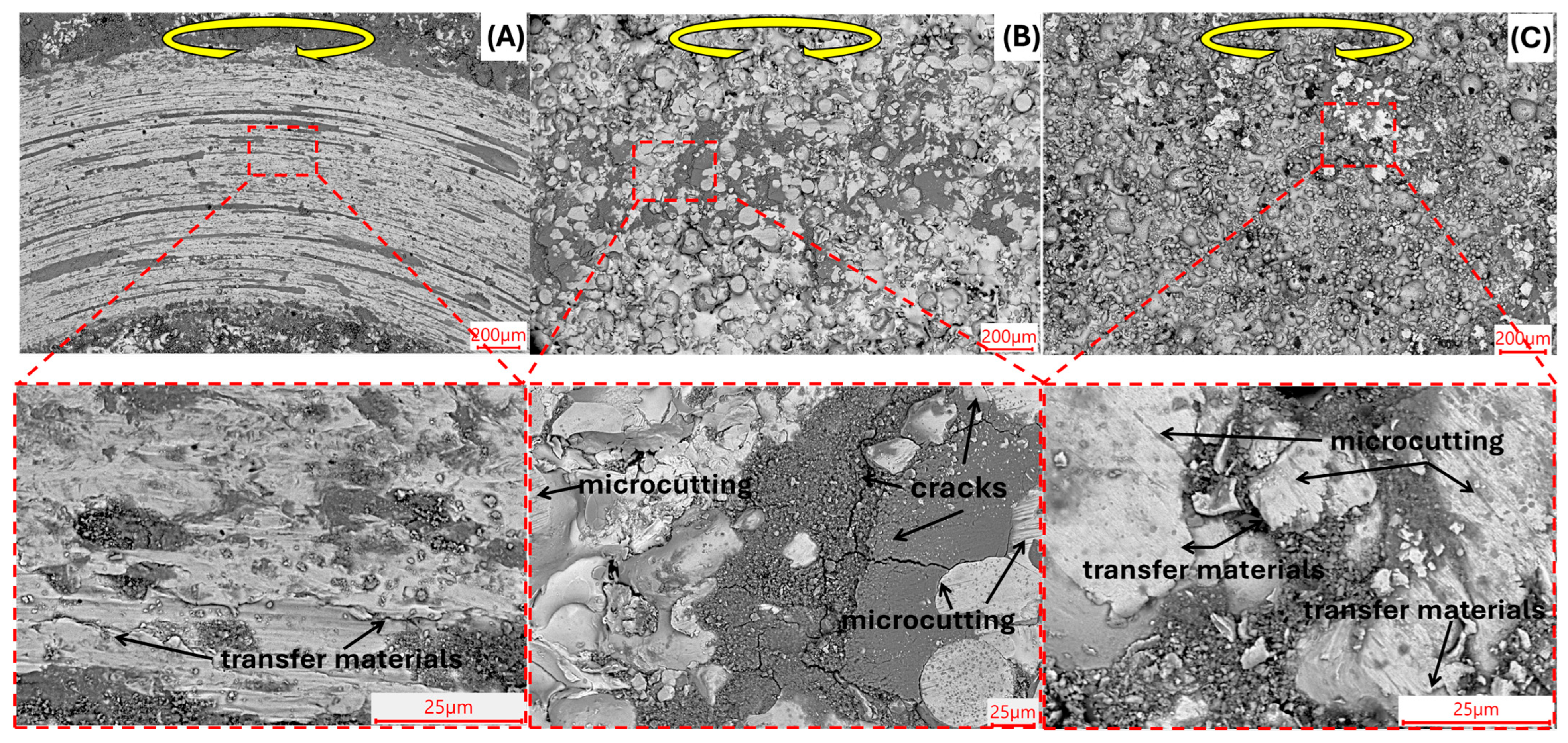
Microgrooves formed during friction, as well as cracks, are clearly visible on the coating surface after flame heating (Figure 10). Microgrooves in this context are the result of local abrasive interaction of the counterbody with surface inclusions or coating irregularities, leading to the cutting out of microparticles and the formation of long traces on the surface. Such areas are often formed in zones where hard phases (carbides, borides) partially protrude above the softer matrix and serve as abrasives during friction. Cracks are formed both along the particle boundaries and within the binder phase, indicating a brittle nature of destruction [45,46].
After furnace treatment, the wear track surface appears more uniform and denser. Although traces of microgrooves are also present, they are less randomly distributed and have a smaller depth and length. Localized layering was also observed, probably occurring along the boundaries of fused particles or between zones with different phase densities. However, the overall surface condition confirms a lower degree of wear. This correlates with the low and stable friction coefficient (0.138 ± 0.003) and indicates a microabrasive but plastically adaptive wear mechanism.
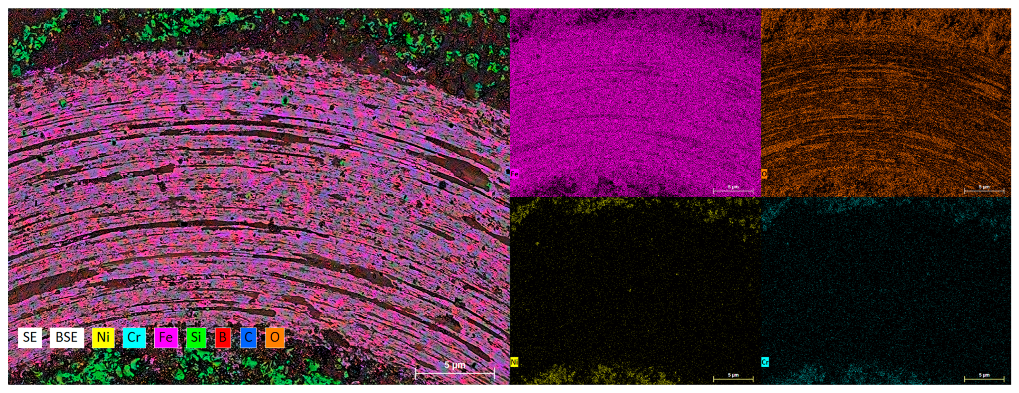
The presented EDS map confirms that the wear track zone is a product of intensive interaction between the coating and the counterbody, accompanied by mechanical destruction and thermal-oxidative effects. The main source of iron in the track zone is the counterbody (for example, a ball made of 100Cr6 steel or equivalent structural steel) (Figure 11). During friction, especially with local heating, the counterbody material migrates to the coating surface. Iron, wearing off from the counterbody, is subject to surface oxidation, as a result of which iron oxides are formed in the track. The formation of such oxide friction products is typical for the oxidative wear regime, in which oxide films are formed on the surface. These films can temporarily reduce the friction coefficient, but when they are destroyed, they become a source of abrasive particles that accelerate wear [47].
For the NiCrFeBSiC coating without heat treatment (A ≈ 0.889 mm2, Figure 12A), a large contact zone with pronounced parallel grooves and ridges along the sliding direction is observed on the wear scar of the 100Cr6 ball, indicating the predominance of three-body abrasion under unstable contact conditions (stick–slip mode). The severe wear of the counterbody indicates that the ball acts as the “weak link” of the pair, with a likely transfer of coating particles onto the ball and subsequent reverse abrasive action [46,47,48]. After flame remelting (A ≈ 0.479 mm2, a reduction in area of ~46% compared to the friction pair where the coating was not heat-treated, Figure 12B), the wear scar is noticeably smaller and more homogeneous, with less pronounced grooves. This is associated with densification and partial remelting of the binder, reduction in porosity, and a more uniform distribution of carbide–boride phases. After furnace heat treatment (A ≈ 0.0395 mm2; a reduction of ~95.6%, Figure 12C), the wear scar is very small: only fine parallel scratches without spallation are visible, which corresponds to a stabilized friction regime with minimal counterbody abrasion. This indicates improved tribocompatibility and a smoother, more stable contact surface of the coating.
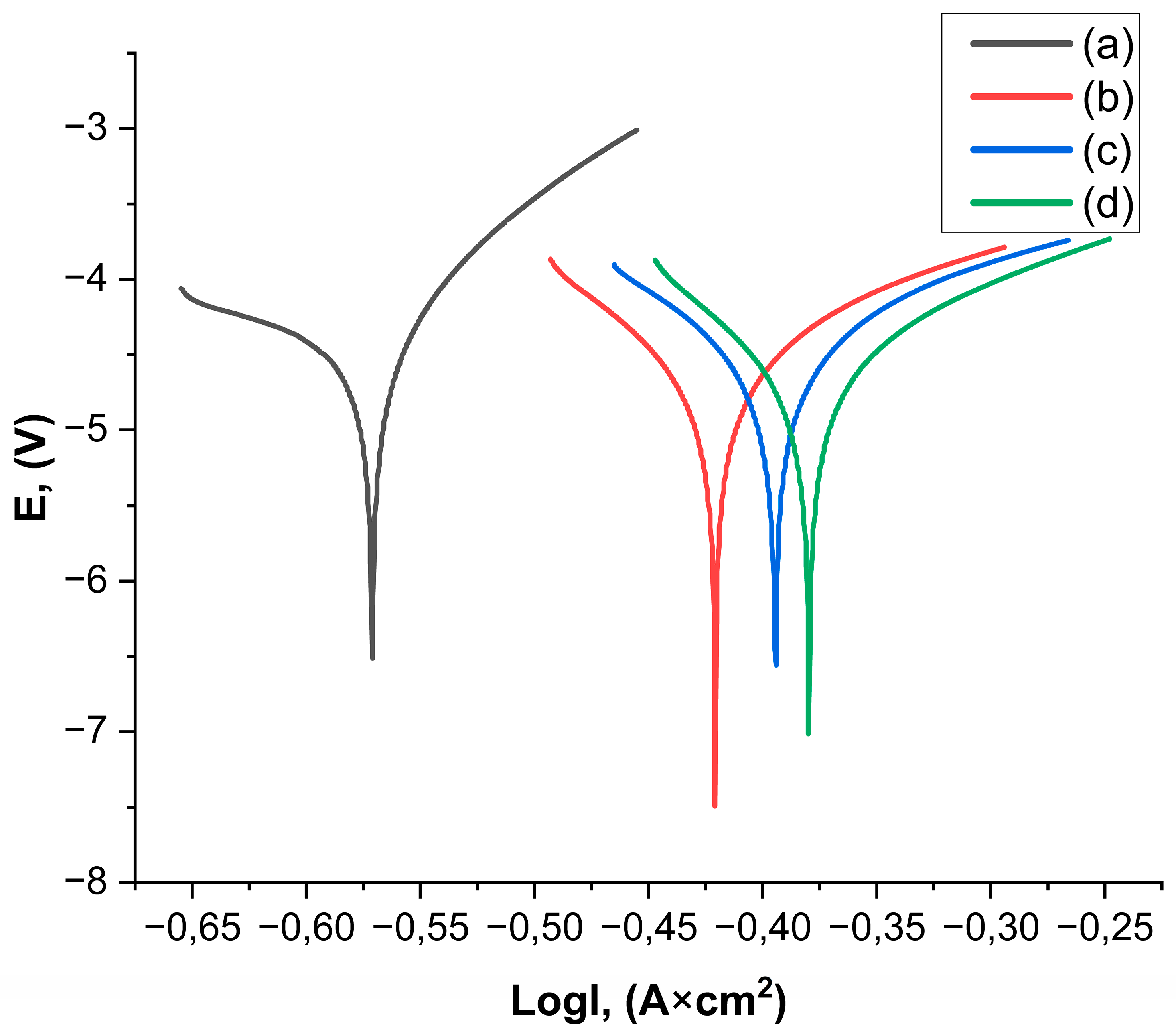
The potentiodynamic curves of all coatings demonstrate a significantly higher corrosion potential for Ecorr compared to AISI 1045 steel (Figure 13).
To describe in detail the corrosion behavior of the samples, the corrosion current was calculated from the slopes of the Tafel sections of the potentiodynamic curves (Table 5) [49,50].
The data presented in Table 4 and the potentiodynamic graph show a significant difference in the corrosion resistance of different types of coatings used for steel. The table shows key parameters such as corrosion current density (Icorr) and corrosion rate (C.R.), which reflect the behavior of materials in corrosion tests [51]. The furnace-heat treated coating demonstrates the best performance with an Icorr value of 0.49634 and a corrosion rate of 0.005678, which is significantly lower compared to other coatings, including AISI 1045 steel and flame-heated and flame-heated coatings. In the potentiodynamic curve graph, it can be seen that the curve for AISI 1045 steel goes into a more negative area on the potential axis, confirming its high corrosion activity. This is reflected in the table data, where the corrosion current density and corrosion rate for steel are maximum. In contrast, flame-heated coatings show good results, although their corrosion resistance is still inferior to that of coatings with subsequent furnace heat treatment. This combination of treatments apparently creates a denser and more corrosion-protected surface that prevents microcracks and moisture retention, significantly slowing down the corrosion process. In general, furnace-heated coatings demonstrate the best corrosion resistance of all the studied options, making it the most promising for use in applications requiring protection from aggressive environments.
The data obtained by measuring the adhesion strength characterize the bonding force between the coating and the substrate (base material). This is one of the key indicators of the quality of coatings obtained by gas-thermal spraying [52]. The results of the adhesion strength tests are presented in the summary table of results (Table 3). The results of contact angle tests by the sitting drop method using an optical goniometer are also shown in Table 3. The data obtained indicates a significant effect of the heat treatment regime on the wettability of the coating surface. The lowest contact angle (53.152°) was recorded for the coating that was not subjected to additional heat treatment. This indicates a high surface energy and a possible microporous structure that promotes wetting with oil. During flame heat treatment, the contact angle increased to 79.875°, which is explained by the compac-tion of the structure, partial sintering of particles and a decrease in microroughness. The highest contact angle (89.603°) was recorded for the sample subject to heat treatment in a furnace. This may be due to the formation of a more homogeneous, dense and, probably, oxidized layer with reduced wettability. Thus, it can be concluded that heat treatment re-duces wettability, which can be a positive factor when operating coatings under friction conditions involving oils.
Adhesion strength tests showed that heat treatment has a significant effect on improving the adhesion of the coating to the substrate. For sample SF1, which was not heat treated, the adhesion strength was 18 MPa (Table 3). For sample SF2, which was remelted with a flame, this indicator increased to 27 MPa (Table 3), indicating the positive effect of this process on the formation of a denser and stronger interphase contact. The highest adhesion strength was recorded for sample SF3, which was heat treated in a furnace, reaching 34 MPa (Table 3).
It is important to note that in all cases, the failure occurred mainly at the interface between the coating and the substrate, which indicates its critical role in the coating-substrate system [53]. The increase in adhesion strength after heat treatment is associated with a number of microstructural factors. First, heating causes partial compaction of the coating and a decrease in porosity, which contributes to an increase in the effective contact area. Second, thermal exposure activates diffusion interaction processes at the interface, leading to a stronger bond between the coating and the substrate. This is particularly evident in furnace heat treatment, where the effect of temperature ensures the formation of a more stable interphase zone with improved mechanical characteristics.
Thus, the gradual increase in adhesion strength values from SF1 to SF3 demonstrates that heat treatment, especially in a furnace, significantly strengthens interphase interaction and increases the operational reliability of coatings.
Figure 14 shows SEM images of indenter prints obtained as a result of microhardness tests of NiCrFeBSiC coatings subjected to various types of thermal action. The study of the prints made it possible to establish a relationship between the type of heat treatment, the microstructural state and the local hardness of the material. Figure 14A shows an indenter print on the coating without heat treatment. The formation of cracks and dips in the print area is clearly visible, which is associated with the presence of pores under the surface layer [54]. Such local load-bearing instability leads to a decrease in microhardness, amounting to 528.7 ± 2.3 HV (Table 3). The obtained data indicate high brittleness of the coating without additional thermal stabilization. Figure 14B illustrates the structure of the coating after flame heating. In this area, the structure is denser compared to the untreated sample. The imprint has a symmetrical shape, the number of cracks is reduced. The microhardness is 771.6 ± 4.6 HV (Table 3), which indicates partial stabilization of the structure and a decrease in internal stresses. Figure 14C corresponds to the coating heated in the furnace. Here, minimal damage to the surface around the imprint is observed, the absence of pronounced cracks and dips, indicating high structural integrity. This is reflected in the highest value of microhardness—922.4 ± 5.7 HV (Table 3), which confirms the effectiveness of heat treatment in the furnace for improving the mechanical properties of the coating.

4. Conclusions

  • Phase composition (XRD): The coatings contain FeNi3 and strengthening carbides/borides (e.g., Cr7C3, Fe23(C,B)6); after heat treatment, the lattice becomes more ordered with an increase in the Ni solid-solution lattice parameter (3.55 → 3.57 Å).
  • Thickness and porosity: Cross-section shows densification (thickness ~805 → 625 → 597 μm), with porosity reduced 7.866% → 3.024% → 1.767% from as-sprayed to flame-remelted to furnace-treated.
  • Roughness (Ra): Surface smoothing with post-treatments: 31.860 → 14.915 → 13.388 μm (minimum after furnace treatment).
  • Microhardness: Near-surface HV increases 528.7 ± 2.3 → 771.6 ± 4.6 → 922.4 ± 5.7 HV, reflecting lower porosity and a stabilized binder.
  • Adhesion strength (ASTM C633): 18 → 27 → 34 MPa; the furnace treatment gives the highest coating–substrate bonding.
  • Wettability (contact angle): Surface becomes less wettable as density increases: 53.152° → 79.875° → 89.603°.
  • Coefficient of friction (dry, ball-on-disk): μ decreases and stabilizes with post-treatments: 0.648 ± 0.070 → 0.173 ± 0.050 → 0.138 ± 0.003; furnace treatment shows the smallest fluctuations.
  • Wear-track morphology: Evolves from pronounced micro-grooves and cracking (as-sprayed) to a more uniform, “polishing-like” track with a thin tribo-film (furnace).
  • Counterbody wear (100Cr6 ball): Wear-scar area shrinks with coating modification (0.889 → 0.479 → 0.0395 mm2), confirming improved tribological compatibility.
  • Corrosion resistance (Tafel): Furnace treatment yields the lowest icorr/CR (e.g., CR ≈ 0.005678 mm·year−1), outperforming AISI 1045 steel and the flame-remelted state.
  • Overall: Among the tested routes, furnace heat treatment at 1025 °C/5 min provides the best structure–property balance (minimum Ra and porosity, maximum HV and adhesion, low and stable μ, enhanced corrosion resistance) and is recommended to extend the service life of NiCrFeBSiC coatings under dry sliding.

Author Contributions

D.B., designed the experiments; N.R. performed the experiments; B.A., T.A. and N.R. contributed to the investigation and methodology; D.B. analyzed the data; D.B. wrote, reviewed, and edited the paper. All authors have read and agreed to the published version of the manuscript.

Funding

This research was funded by the Science Committee of the Ministry of Science and Higher Education of the Republic of Kazakhstan (Grant No. BR24992876).

Institutional Review Board Statement

Not applicable.

Informed Consent Statement

Not applicable.

Data Availability Statement

Data are contained within the article. The original contributions presented in this study are included in the article. Further inquiries can be directed to the corresponding author.

Conflicts of Interest

The authors declare that there are no conflicts of interest regarding the publication of this manuscript.

References

  1. Kusumar, Nerlfi & Growney Publish Third Global Paint & Coatings Report, 2016–2021. Available online: https://www.coatingsworld.com/issues/2017-09-01/view_market-research/kusumgar-nerlfi-amp-growney-publish-third-global-p/ (accessed on 13 May 2025).
  2. Pawlowski, L. The Science and Engineering of Thermal Spray Coatings, 2nd ed.; John Wiley & Sons, Ltd.: Chichester, UK, 2008. [Google Scholar]
  3. Havrlisan, S.; Simunovic, K.; Vukelic, D. Modelling of abrasive wear of Ni-based self-fluxing alloy coatings by the application of experimental design. Tech. Gaz. 2006, 23, 1687–1693. [Google Scholar] [CrossRef]
  4. Váz, R.; Tristante, R.; Pukasiewicz, A.; Capra, A.; Chicoski, A.; Filippin, C. Welding and thermal spray processes for maintenance of hydraulic turbine runners: Case studies. Soldag. Inspeção. 2021, 25, 2540. [Google Scholar] [CrossRef]
  5. Vardavoulias, M. Industrial component restoration using thermal spray technologies. In Industrial Component Restoration Using Thermal Spray Technologies; CRC Press: Boca Raton, FL, USA, 2023. [Google Scholar] [CrossRef]
  6. Vernhes, L. Thin Coatings for Heavy Industry: Advanced Coatings for Pipes and Valves. Ph.D. Thesis, Université de Montréal, Montréal, QC, Canada, 2015. Available online: https://publications.polymtl.ca/1686/1/2015_LucVernhes.pdf (accessed on 21 September 2025).
  7. Zhang, X.; Luo, T.; Liu, S.; Zheng, Z.; Wang, J.; Zheng, K.; Wang, S.; Chen, H. Microstructure and Corrosion Behavior of Fe-Based Austenite-Containing Composite Coatings Using Supersonic Plasma Spraying. Coatings 2023, 13, 694. [Google Scholar] [CrossRef]
  8. Lee, C.-Y.; Lin, T.-J.; Sheu, H.-H.; Lee, H.-B. A study on corrosion and corrosion-wear behavior of Fe-based amorphous alloy coating prepared by high velocity oxygen fuel method. J. Mater. Res. Technol. 2021, 15, 4880–4895. [Google Scholar] [CrossRef]
  9. Umanskyi, O.P.; Storozhenko, M.S.; Baglyuk, G.A.; Melnyk, O.V.; Brazhevsky, V.P.; Chernyshov, O.O.; Terentiev, O.E.; Gubin, Y.V.; Kostenko, O.D.; Martsenyuk, I.S. Structure and wear resistance of plasma-sprayed NiCrBSiC–TiCrC composite powder coatings. Powder Metall. Met. Ceram. 2020, 59, 434–444. [Google Scholar] [CrossRef]
  10. Abderrahmane, A.; Gaceb, M.; Cheikh, M.; LE Roux, S. Wear Behavior and Microstructure of Thermally Sprayed NiCrBSiFeC and Composite NiCrBSiFeC-WC(Co) Coatings. Mater. Sci. 2021, 27, 175–183. [Google Scholar] [CrossRef]
  11. Kazamer, N.; Vălean, P.; Pascal, D.-T.; Muntean, R.; Mărginean, G.; Șerban, V.-A. Development, optimization, and characterization of NiCrBSi-TiB2 flame-sprayed vacuum fused coatings. Surf. Coat. Technol. 2021, 406, 126747. [Google Scholar] [CrossRef]
  12. Monção, F.C.; Caliari, F.R.; Freitas, F.E.; Couto, A.A.; Augusto, A.; Lima, C.R.C.; Massi, M. Wear Resistance Evaluation of Self-Fluxing Nickel-Based Coating Deposited on AISI 4340 Steel by Atmospheric Plasma Spray. Metals 2024, 14, 532. [Google Scholar] [CrossRef]
  13. Shieh, Y.-H.; Wang, J.-T.; Shih, H.C.; Wu, S.-T. Allowing and post-heat treatment of thermal sprayed coatings of self-fluxing alloys. Surf. Coat. Technol. 1993, 58, 73–78. [Google Scholar] [CrossRef]
  14. Cha, S.C.; Gudenau, H.W.; Bayer, G.T. Comparison of corrosion behaviour of thermal sprayed and diffusion-coated materials. Mater. Corros. 2002, 53, 195–205. [Google Scholar] [CrossRef]
  15. Mahesh, C. Multiscale abinitio simulation of Ni-based alloys: Real-space distribution of atoms in γ + γ’ phase. Comp. Mater. Sci. 2015, 108, 192–204. [Google Scholar]
  16. Gagandeep, S.; Manpreet, K.; Rohit, U. Wear and friction behavior of NiCrBSi coatings at elevated temperatures. J. Therm. Spray Technol. 2019, 28, 1081–1102. [Google Scholar]
  17. Afsous, M.; Shafyei, A.; Soltani, M.; Eskandari, A. Characterization and evaluation of tribological properties of NiCrBSi–Gr composite coatings deposited on stainless steel 420 by HVOF. J. Therm. Spray Technol. 2020, 29, 773–788. [Google Scholar] [CrossRef]
  18. Tang, L.; Kang, J.; He, P.-F.; Ding, S.-Y.; Chen, S.-Y.; Liu, M.; Xiong, Y.-C.; Ma, G.Z.; Wang, H. Effects of spraying conditions on the microstructure and properties of NiCrBSi coatings prepared by internal rotating plasma spraying. Surf. Coat. Technol. 2019, 374, 625–633. [Google Scholar] [CrossRef]
  19. García, A.; Fern’andez, M.R.; Cuetos, J.M.; Gonz’alez, R.; Ortiz, A.; Cadenas, M. Study of the sliding wear and friction behavior of WC + NiCrBSi laser cladding coatings as a function of actual concentration of WC reinforcement particles in ball-on-disk test. Tribol. Lett. 2016, 63, 41. [Google Scholar] [CrossRef]
  20. Guo, C.; Zhou, J.; Chen, J.; Zhao, J.; Yu, Y.; Zhou, H. High temperature wear resistance of laser cladding NiCrBSi and NiCrBSi/WC-Ni composite coatings. Wear 2011, 270, 492–498. [Google Scholar] [CrossRef]
  21. Xiao, J.-K.; Wu, Y.-Q.; Zhang, W.; Chen, J.; Wei, X.-L.; Zhang, C. Microstructure, wear and corrosion behaviors of plasma sprayed NiCrBSi-Zr coating. Surf. Coat. Technol. 2019, 360, 172–180. [Google Scholar] [CrossRef]
  22. Gonzalez, R.; Garcia, M.A.; Penuelas, I.; Cadenas, M.; del Rocio Fernandez, M.; Hernandez Battez, A.; Felgueroso, D. Microstructural Study of NiCrBSi Coatings Obtained by Different Processes. Wear 2007, 263, 619–624. Available online: http://www.sciencedirect.com/science/article/pii/S0043164807004061 (accessed on 25 September 2025). [CrossRef]
  23. Li, Q.; Zhang, D.; Lei, T.; Chen, C.; Chen, W. Compari son of laser-clad and furnace-melted Ni-based alloy microstruc tures. Surf. Coat. Technol. 2001, 137, 122–135. Available online: http://www.sciencedirect.com/science/article/pii/S0257897200007325 (accessed on 29 September 2025). [CrossRef]
  24. Navas, C.; Colaco, R.; de Damborenea, J.; Vilar, R. Abrasive Wear Behaviour of Laser Clad and Flame Sprayed melted NiCrBSi Coatings. Surf. Coat. Technol. 2006, 200, 6854–6862. [Google Scholar] [CrossRef]
  25. Kim, H.-J.; Hwang, S.-Y.; Lee, C.-H.; Juvanon, P. Assessment of Wear Performance of Flame Sprayed and Fused Ni-based Coatings. Surf. Coat. Technol. 2003, 172, 262–269. [Google Scholar] [CrossRef]
  26. Hemmati, I.; Rao, J.C.; Ocelík, V.; De Hosson, J.T.M. Electron Microscopy Characterization of Ni-Cr-B-Si-C Laser Deposited Coatings. Microsc. Microanal. 2013, 19, 120–131. [Google Scholar] [CrossRef]
  27. ASTM A108; Standard Specification for Steel Bar, Carbon and Alloy, Cold-Finished. ASTM International: West Conshohocken, PA, USA, 2024.
  28. ISO/TR 26946:2011; Standard Method for Porosity Measurement of Thermally Sprayed Coatings. International Organization for Standardization: Geneva, Switzerland, 2011.
  29. Górka, J.; Lont, A.; Poloczek, T. The Microstructure and Properties of Laser Cladded Ni Based Self Fluxing Alloy Coatings Reinforced by TiC Particles. Coatings 2025, 15, 527. [Google Scholar] [CrossRef]
  30. Buitkenov, D.; Rakhadilov, B.; Nabioldina, A.; Mukazhanov, Y.; Adilkanova, M.; Raisov, N. Investigation of Structural Phase, Mechanical, and Tribological Characteristics of Layer Gradient Heat-Protective Coatings Obtained by the Detonation Spraying Method. Materials 2024, 17, 5253. [Google Scholar] [CrossRef]
  31. Sagdoldina, Z.; Baizhan, D.; Sulyubayeva, L.; Berdimuratov, N.; Buitkenov, D.; Bolatov, S. Effect of Electrofriction Treatment on Microstructure, Corrosion Resistance and Wear Resistance of Cladding Coatings. Coatings 2024, 14, 1433. [Google Scholar] [CrossRef]
  32. ASTM C633-15(2020); Standard Test Method for Adhesion or Cohesion Strength of Thermal Spray Coatings. ASTM International: West Conshohocken, PA, USA, 2020.
  33. ISO 19403-2:2024; Paints and Varnishes—Wettability—Part 2: Determination of Surface Free Energy of Solid Surfaces by Measuring the Contact Angle. International Organization for Standardization: Geneva, Switzerland, 2024.
  34. ISO 6507-1:2018; Metallic Materials—Vickers Hardness Test—Part 1: Test Method. International Organization for Standardization: Geneva, Switzerland, 2018.
  35. Wang, Y.; Stella, J.; Darut, G.; Poirier, T.; Liao, H.; Planche, M.-P. APS prepared NiCrBSi-YSZ composite coatings for protection against cavitation erosion. J. Alloys Compd. 2017, 699, 1095–1103. [Google Scholar] [CrossRef]
  36. Serres, N.; Hlawka, F.; Costil, S.; Langlade, C.; Machi, F. Microstructure and Environmental Assessment of Metallic NiCrBSi Coatings Manufactured via Hybrid Plasma Spray Process. Surf. Coat. Technol. 2010, 205, 1039–1046. [Google Scholar] [CrossRef]
  37. Muzamil, M.; Iqbal, S.A.; Anwar, M.N.; Samiuddin, M.; Yang, J.; Raza, M.A. Wear Behavior assessment of new wire-arc additively manufactured surfaces on AA6061 and AA5086 alloys through multi-walled carbon nanotubes and Ni particles inducement. Coatings 2024, 14, 429. [Google Scholar] [CrossRef]
  38. Miguel, J.M.; Guilemany, J.M.; Vizcaino, S. Tribological study of NiCrBSi coating obtained by different processes. Tribol. Int. 2003, 36, 181–187. [Google Scholar] [CrossRef]
  39. Baydoun, S.; Moul-El-Ksour, F.Z.; Fouvry, S.; Guillonneau, G.; Pereira, J.C.; Santos, F.; Rocchi, J. Tribological investigation of new self-fluxing nickel alloys for high temperature application: The effect of silicon distribution on glaze layer formation. Wear 2025, 564, 205631. [Google Scholar] [CrossRef]
  40. Chen, T.; Wu, F.; Wang, H.; Liu, D. Laser cladding in-situ Ti(C,N) particles reinforced Ni-based composite coatings modified with CeO2 nanoparticles. Metals 2018, 8, 601. [Google Scholar] [CrossRef]
  41. Huang, J.; Wu, J.; Yu, J.; Xu, Y.; Yan, J.; Li, J. Evaluation of Adhesion Strength of Thermally Sprayed Coatings: Limitations of the ASTM C633 Standard and Alternative Testing Approaches. Materials 2024, 17, 5069. [Google Scholar] [CrossRef]
  42. Rakhadilov, B.; Buitkenov, D.; Sagdoldina, Z.; Idrisheva, Z.; Zhamanbayeva, M.; Kakimzhanov, D. Preparation and Characterization of NiCr/NiCr-Al2O3/Al2O3 Multilayer Gradient Coatings by Gas Detonation Spraying. Coatings 2021, 11, 1524. [Google Scholar] [CrossRef]
  43. Houdková, Š.; Smazalová, E.; Vostřák, M.; Schubert, J. Properties of NiCrBSi coating, as sprayed and remelted by different technologies. Surf. Coat. Technol. 2014, 253, 14–26. [Google Scholar] [CrossRef]
  44. Rakhadilov, B.; Pogrebnjak, A.; Zhuldyz, S.; Buitkenov, D.; Beresnev, V.; Mukhamedova, A. Effect of Bilayer Thickness and Bias Potential on the Structure and Properties of (TiZr/Nb)N Multilayer Coatings as a Result of Arc-PVD Deposition. Materials 2022, 15, 7696. [Google Scholar] [CrossRef]
  45. Rakhadilov, B.; Sulyubayeva, L.; Maulet, M.; Sagdoldina, Z.; Buitkenov, D.; Issova, A. Investigation of High-Temperature Oxidation of Homogeneous and Gradient Ni-Cr-Al Coatings Obtained by Detonation Spraying. Coatings 2024, 14, 11. [Google Scholar] [CrossRef]
  46. Dzhurinskiy, D.; Babu, A.; Pathak, P.; Elkin, A.; Dautov, S.; Shornikov, P. Microstructure and wear properties of atmospheric plasma-sprayed Cr3C2-NiCr composite coatings. Surf. Coat. Technol. 2021, 428, 127904. [Google Scholar] [CrossRef]
  47. Meiirbekov, M.; Ismailov, M.; Kenzhegulov, A.; Mustafa, L.; Tashmukhanbetova, I. Study of the effect of combined reinforcement and modification of epoxy resin with rubbers on the impact strength of carbon fiber-reinforced plastic. Eurasian J. Phys. Funct. Mater. 2024, 8, 3. [Google Scholar] [CrossRef]
  48. Rojacz, H.; Zikin, A.; Mozelt, C.; Winkelmann, H.; Badisch, E. High temperature corrosion studies of cermet particle reinforced NiCrBSi hardfacings. Surf. Coat. Technol. 2013, 222, 90–96. [Google Scholar] [CrossRef]
  49. Bakhytuly, N.; Kenzhegulov, A.K.; Nurtanto, M.; Aliev, A.E.; Kuldeev, E.l. Microstructure and tribological study of TiAICN and TiTaCN coatings. Complex Use Miner. Resour. 2023, 327, 99–110. [Google Scholar] [CrossRef]
  50. González, R.; García, M.A.; Peñuelas, I.; Cadenas, M.; Fernández, M.D.R.; Battez, A.H. Microstructural study of NiCrBSi coatings obtained by differ ent processes. Wear 2007, 263, 619–624. [Google Scholar] [CrossRef]
  51. Fernández, E.; Cadenas, M.; González, R.; Navas, C.; Fernández, R.; De Damborenea, J. Wear behaviour of laser clad NiCrBSi coating. Wear 2005, 259, 870–875. [Google Scholar] [CrossRef]
  52. Hemmati, I. Evolution of microstructure and properties in laser cladding of a Ni-Cr–B–Si hardfacing alloy. Surf. Eff. Contact Mech. 2011, 71, 287–296. [Google Scholar] [CrossRef]
  53. Hemmati, I.; Ocelík, V.; De Hosson, J.T.M. Dilution effects in laser cladding of Ni Cr–B–Si–C hardfacing alloys. Mater. Lett. 2012, 84, 69–72. [Google Scholar] [CrossRef]
  54. Rakhadilov, B.; Kakimzhanov, D.; Baizhan, D.; Muslimanova, G.; Pazylbek, S.; Zhurerova, L. Comparative Study of Structures and Properties of Detonation Coatings with α-Al2O3 and γ-Al2O3 Main Phases. Coatings 2021, 11, 1566. [Google Scholar] [CrossRef]
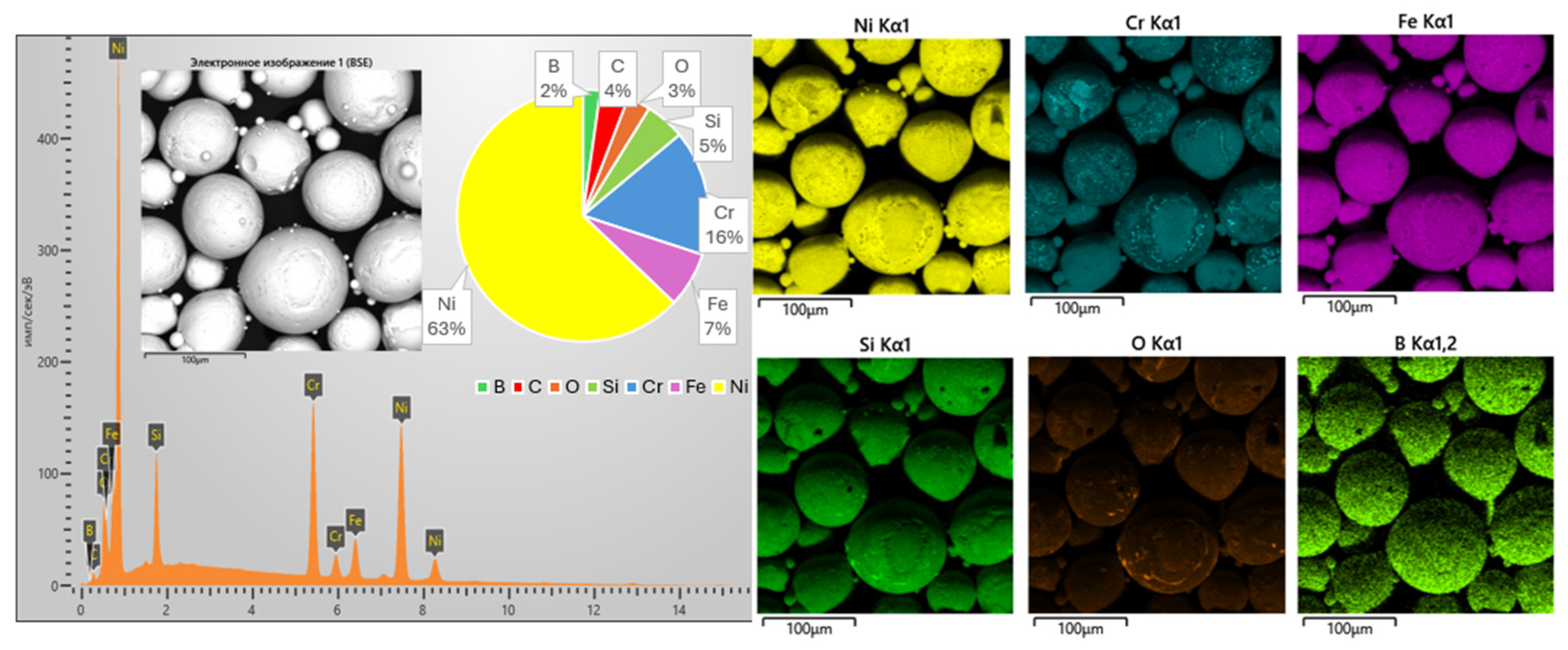
Figure 1. Morphology of self-fluxing NiCrFeBSiC powder.
Crystals 15 00862 g001
Figure 2. Scheme of the installation for flame spraying.
Crystals 15 00862 g002
Figure 3. Schematic of the heat treatment of NiCrFeBSiC coatings.
Crystals 15 00862 g003
Figure 4. Schematic diagram of the Potentiostat CS310 setup for conducting an electrochemical corrosion experiment [29].
Crystals 15 00862 g004
Figure 5. Map of distribution of elements on the surface of coatings made of self-fluxing NiCrFeBSiC powder.
Crystals 15 00862 g005
Figure 6. XRD spectra of the powder and NiCrFeBSiC coatings: (SF1) without heat treatment; (SF2) after flame heating with a gas-flame torch; (SF3) after furnace heating.
Crystals 15 00862 g006
Figure 7. Investigation of porosity (bottom row) and thickness (top row) of NiCrFeBSiC coatings in cross section: (A) without heating—SF1; (B) flame heating—SF2; (C) furnace heating—SF3.
Crystals 15 00862 g007
Figure 8. Micrographs of the surfaces (top row) and corresponding surface roughness profile graphs (bottom row): (A) without heat treatment—SF1; (B) after flame heating—SF2; (C) after furnace heating—SF3.
Crystals 15 00862 g008
Figure 9. Results of tribological tests of the coatings using the “ball-on-disk” configuration under dry sliding conditions: (SF1) without heat treatment; (SF2) after flame heating; (SF3) after furnace heating.
Crystals 15 00862 g009
Figure 10. Results of tribological tests using the “ball-on-disk” configuration under dry sliding conditions: (A) without heat treatment—SF1; (B) after flame heating—SF2; (C) after furnace heating—SF3.
Crystals 15 00862 g010
Figure 11. Energy-dispersive spectroscopy (EDS) elemental map of the wear track surface of the NiCrFeBSiC coating after furnace heat treatment.
Crystals 15 00862 g011
Figure 12. Wear scars of the counterbody (100Cr6 ball) after sliding against the NiCrFeBSiC coating in different coating states: (A) 100Cr6 ball in a friction pair with the coating without heat treatment; (B) 100Cr6 ball in a friction pair with the coating after flame remelting; (C) 100Cr6 ball in a friction pair with the coating after furnace heat treatment.
Crystals 15 00862 g012
Figure 13. Potentiodynamic curves: (a) base steel; (b) without heat treatment— SF1; (c) after flame heating—SF2; (d) after furnace heating—SF3.
Crystals 15 00862 g013
Figure 14. SEM images of indenter impressions on NiCrFeBSiC coatings (A) without heat treatment; (B) after flame heating; (C) after furnace heating.
Crystals 15 00862 g014
Table 1. Chemical composition of 1045 steel.
Steel GradeCCuMnAsNiPSSiFe
10450.470.280.780.070.200.0350.0400.2797.85
Table 2. Gas flame spraying parameters for obtaining coatings.
Operation gasOxygen 25 NLPM
Acetylene15 NLPM
Powder carrier gasAir37 NLPM
Spraying distance200 mm
Spray time30 s
Table 3. Mechanical, tribological, and surface properties of the coatings.
SamplesAdhesion Strength, MPaMicrohardness,
HV0.05
Wettability,
°
Friction CoefficientRoughness, μm
SF118528.7 ± 2.353.1520.648 ± 0.07031.860 ± 0.290
SF227771.6 ± 4.679.8750.173 ± 0.05014.915 ± 0.047
SF334922.4 ± 5.789.6030.138 ± 0.00313.388 ± 0.016
Table 4. Wear rate values of tested samples determined from worn track cross-section analysis.
Sample NameSample Wear Rate [mm3/(N·m)]
SF10.001694 ± 0.000085
SF24.102 × 10−6 ± 0.205 × 10⁻⁵
SF33.458 × 10−6 ± 0.173 × 10⁻⁶
Table 5. Results of measuring the corrosion resistance of self-fluxing NiCrFeBSiC coatings.
SamplesInitial
AISI 1045 Steel
SF1SF2SF3
Icorr (A)0.692180.423710.394660.38963
icorr (A/cm2)0.8817579620.5397579620.5027515920.496343949
CR (mm/a)0.01008731220.0061748320.0057514790.005678175
Disclaimer/Publisher’s Note: The statements, opinions and data contained in all publications are solely those of the individual author(s) and contributor(s) and not of MDPI and/or the editor(s). MDPI and/or the editor(s) disclaim responsibility for any injury to people or property resulting from any ideas, methods, instructions or products referred to in the content.