Review

Recent Progress of Floating-Zone Techniques for Bulk Single-Crystal Growth

National Institute for Materials Science, 3-13 Sakura, Tsukuba 305-0003, Japan
Crystals 2024, 14(6), 552; https://doi.org/10.3390/cryst14060552
Submission received: 28 May 2024 / Revised: 10 June 2024 / Accepted: 12 June 2024 / Published: 14 June 2024

Abstract

:
This review describes the recent progress of floating-zone techniques for bulk single-crystal growth. The most crucial point of the crucible-free technique is to keep the molten zone stable. It has been investigated and reported to yield a steeper temperature gradient at the liquid–solid interface along the growth direction and a homogeneous molten liquid along the rotation axis. This article overviews several recent achievements starting from the conventional setup, particularly for lamps equipped in horizontal or vertical configurations, tilting mirrors, shielding the irradiation, and filament sizes for the optical-lamp floating-zone furnaces. Also, the recently advancing laser-heated floating-zone furnaces are described. Throughout the article, the author emphasizes that the floating-zone technique has been a powerful tool for crystal growth since the 1950s with its roots in the zone-melting method, and it has still been advancing for further materials’ growth such as quantum materials with modern scientific concepts.

1. Introduction

“The importance of a knowledge of the physical properties of single crystals of the metals requires no argument” [1]. This statement, written a century ago by Nobel laureate P.W. Bridgman, still has significant implications for the modern field of materials science. Understanding the fundamental properties of bulk materials is vital, and it is a prerequisite for research using single crystals to derive the thermodynamic, magnetic, electric, structural, and mechanical properties reflecting the anisotropic crystal structures and their influenced interactions among electrons. Unveiling the detailed bulk properties of the material is the first step because these can motivate further steps of investigation/application toward the fabrication process for thin films or nano-structured devices/sensors to maximize/optimize the properties. Among the huge variety of materials ranging from metallic alloys, oxides, chalcogenides, and organics, so-called “quantum materials” have attracted considerable attention these days [2,3] because of their exotic phases, for instance, novel magnetism including quantum spin liquid states, multiferroicity, and unconventional superconductivity, research subjects which have been boosted by the discovery by heavy fermion intermetallics, cuprates, and organics [4,5,6]. A significant point of the materials is that these phases can be controllable by small perturbations: chemical substituting or doping of other elements, (uniaxial) pressure, magnetic field, and gate tuning [7,8]. In addition, the originally mathematical concept of “topology” recently introduced in materials science provides novel properties such as non-saturating magnetoresistance, the (quantum) anomalous Hall effect, and the anomalous Nernst effect. The new category of materials opens a new window as “topological materials” such as Dirac, Weyl, and magnetic semimetals originating from the quantum mechanical “Berry phase” [9,10,11,12,13,14]. Also, the conceptualization of “altermagnets” has been rapidly developing in the last few years in which the spin structure behaves like antiferromagnets with no net magnetism, while the system breaks parity and time-reversal symmetries like ferromagnets because of the alternation of lattice symmetry neighboring the magnetic ions [15,16,17,18]. Along with the significant advances of the first-principles calculations and theories, materials design has been developing based on these backgrounds. Therefore, the growth of bulk single crystals with high quality has been in high demand [19].
Among several techniques for growing single-crystals such as Bridgman, Czochralski, flux, and chemical vapor transport, the floating-zone technique has been developed since the 1950s with its roots in the zone-melting method [20]. The advantage of the technique is that it is crucible-free so that accidental contamination can be minimized during the growth process. This is crucial for quantum materials because novel properties can emerge only when the purity of the materials is high enough and the ground states can easily be modified. Also, obtaining large and homogeneous crystals is another advantage of the technique. These advantages offer opportunities for deeper investigations of the materials because several experimental methods can be examined. This is indispensable for a systematic understanding of the materials in which the magnetic, electronic, thermal, and topological properties are strongly linked [21,22,23]. Quantum materials have potential applications such as quantum computing, devices/sensors supporting an IoT society, and even energy materials that will be the basis of next-generation societies [24,25,26].
Since the successful growth of silicon in the middle of the last century [27,28], the floating-zone technique has been widely applied to various categories of materials: oxides [29,30,31,32,33,34,35,36,37,38,39,40,41,42,43,44,45], chalcogenides [46,47,48,49], silicides [50,51,52,53,54,55], borides [56,57,58,59,60,61,62,63], carbides [64,65,66,67,68,69,70], and intermetallic alloys [71,72,73,74,75,76,77,78,79,80]. For each material, the growth has been optimized by improving the processes and conditions, for example, rod preparation, generating power to locally melt the rods, feed/growth and rotation speeds, and the atmosphere/pressure of the growth area. Following the long history of the techniques of more than half a century, excellent review articles or books are available to catch up on how it has succeeded in growing a variety of materials [37,81,82,83,84,85,86]. The technique might be “well-established” based on its concrete and clear principle but is never “old-fashioned”. The technique has advanced steadily in recent years, along with the increasing demand for high-quality crystals of quantum materials with modern concepts. Therefore, it is a good opportunity to review the recent progress. Here, this article focuses on developing light conversion which is the essential point of the technique to keep the molten liquid-zone stable. This article overviews several achievements by briefly describing their advantages.

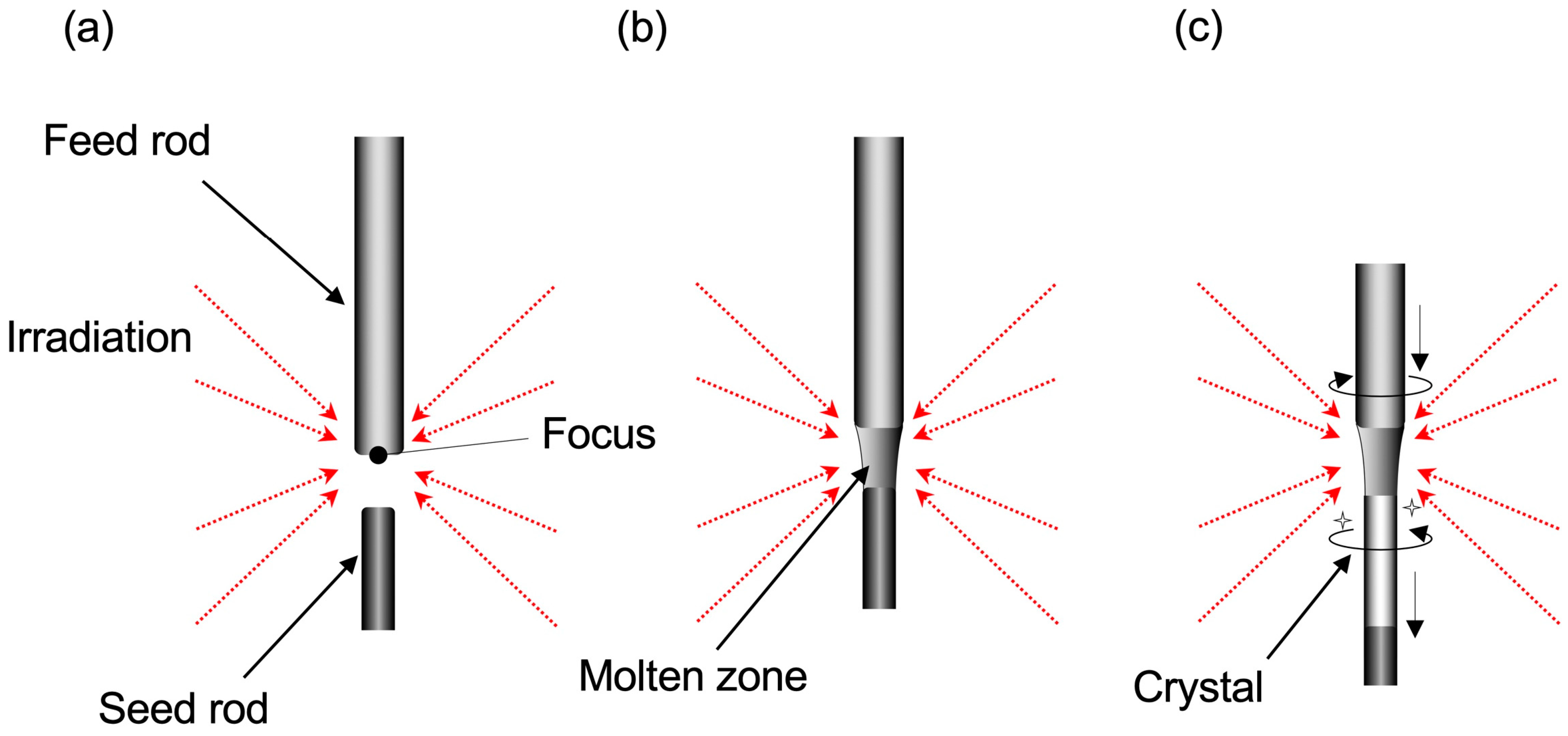
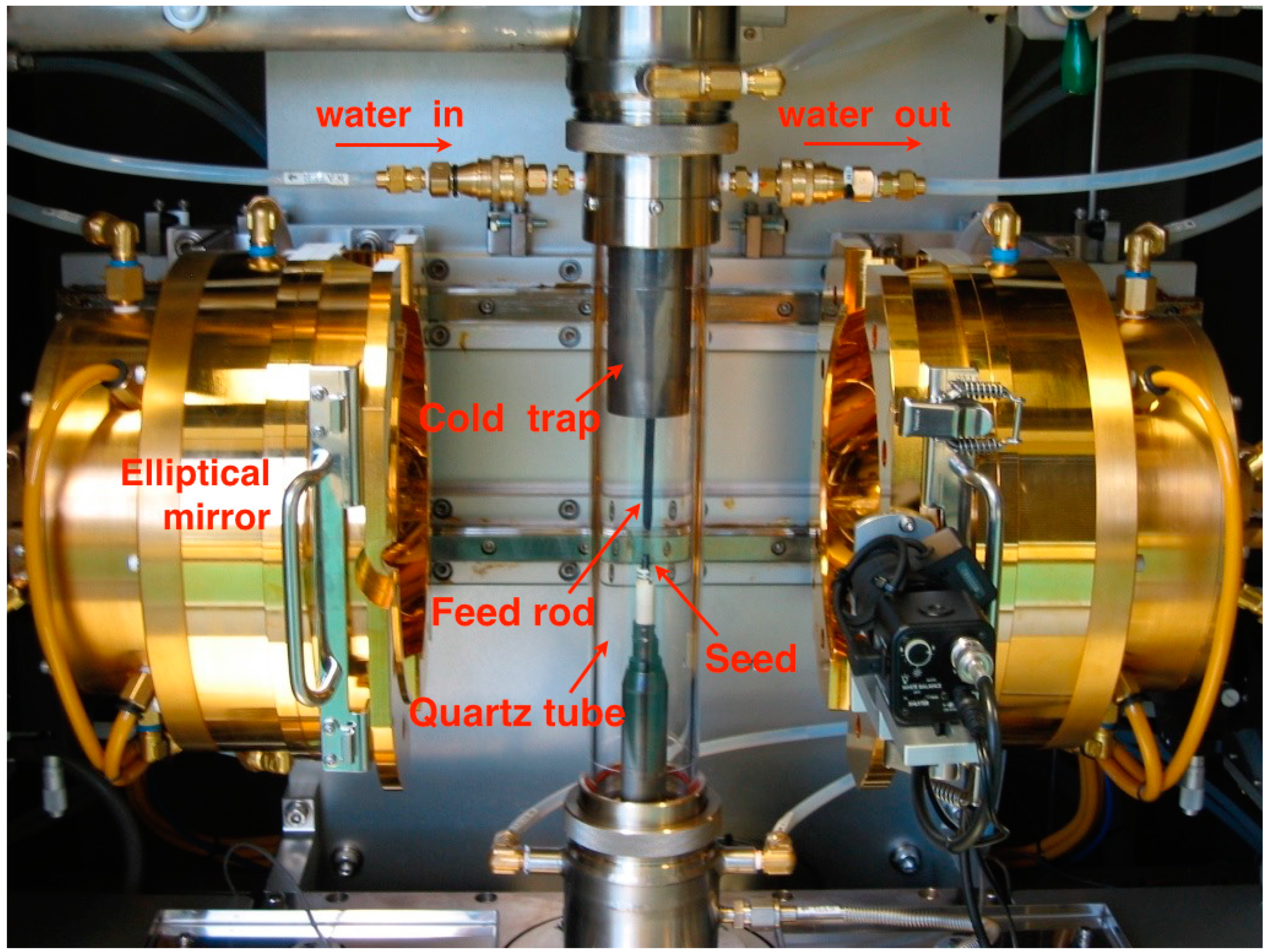
2. Principle of the Floating-Zone Technique

The author starts with an introductory description of the floating-zone method, as presented in Figure 1. First, the bottom edge of a polycrystalline feed rod is locally heated (Figure 1a). When the edge starts to melt, the edge of the seed rod approaches the molten rod. Then, the molten zone is formed when the molten feed rod is connected to the seed rod (Figure 1b). Once the molten zone forms steadily, both rods are moved steadily out of the molten area, then the single crystal is eventually formed on the top of the seed rod (Figure 1c). The feed and seed rods are usually counterrotated for better uniform mixing of the melting liquid. Since the growth area is isolated by a transparent quartz tube from the outside (Figure 2), we can choose the desirable gas and its (partial) pressure for growth. Today, growth is available even under an extremely high vacuum [87] and high pressure [88], and even extremely low-oxygen partial pressure [89], depending on the properties of the target materials.
Here, one of the key points to growing high-quality crystals is to keep the molten zone stable against vibrations and down-spilling, because it is supported only by the fragile surface tensions between the feed rod and the seed rod. Also, the viscosity of the molten liquid, which is inherent to the material, is closely linked to the liquid-zone stability; if the generated power is excessive, the molten zone can eventually cause down-spilling. That forcibly terminates the growth because the stacking of the crystal is lost. In contrast, if the generated power is insufficient, the zone is vibrated unstably. The vibration finally prevents uniform growth hereafter. Thus, the fragile molten zone is an inevitable “trade-off” against the most relevant advantage of the technique, which is “crucible-free”. Therefore, forming a better stable zone has been a challenging topic, and it has been recognized that there are mainly two points for the stable zone: one is to generate a sharp temperature gradient along the growth direction, and the other is to form a homogeneous liquid along the radial direction of the rod. To gain these points, introducing modern and precise technologies to the furnaces has been crucial for the further success of crystal growth under stable conditions.
The local heating/irradiation toward the focus is essential for the stable zone. The heating has been generated by radio frequency [79], electron beam [80], and arc heating [90]. In addition, optical or laser heating has been adopted these days in most cases. The former case of optical heating has been widespread and popular, as sketched in Figure 2a, but it has still been improved. In contrast, the latter heating techniques using laser sources (Figure 2b) have been remarkably progressing, along with the rapid advance of laser techniques these days. This article overviews several remarkable developments and progress with a focus on these two heating methods.

3. Floating-Zone Furnaces with Optical Lamps

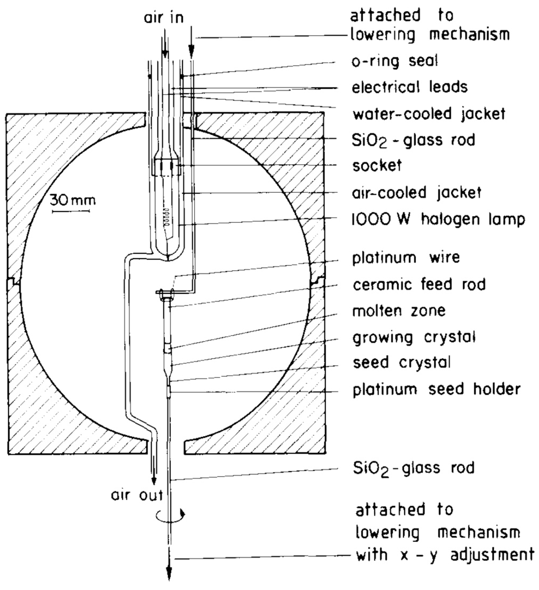
3.1. Optical Lamps Equipped in the Horizontal Configurations

The author describes the optical floating-zone furnaces, particularly, the most popular type with the horizontally configurated optical lamps. Figure 3a,b present schematic drawings of the typical optical floating zone furnaces with four and two mirrors, respectively [21]. Both cases are drawn from the top view, and the lamps are set in the horizontally transverse configuration against the growth direction. As shown in Figure 2a, in the case of a simpler double-mirror furnace (Figure 3b), since a halogen lamp is set to one of the focal points of the elliptical mirror, the radiation from it reflected at the mirror surface converges at the other focal point. The focused area, potentially reaching over 2000 °C, is shared with the other converged area from the radiation of the second lamp. The molten zone is formed due to the convergence of the irradiation lights reflected from the surrounding mirrors. Thus far, many materials have been successfully grown using the technique, as described above.
As seen in the schematic drawing of the lower panels of Figure 3a,b, a concern that may affect some materials is the profile of the light intensity in the molten area. Here, the profile yields “oscillation” as a function of azimuthal rotation angle along the transverse plane (denoted as θ in the figures) [21]. Although the four-mirror geometry has a better temperature profile than the double-mirror one, the “oscillating” temperature distribution along the in-plane azimuthal angle may cause “nonuniformity” in the liquid zone. The “nonuniformity” may cause an inhomogeneous liquid and prevent us from obtaining high-quality crystals. To avoid the inhomogeneity of the liquid, the counterrotation between the feed and seed rods may work to relax the nonuniformity.

3.2. Optical Lamps Equipped in the Vertical Configurations

Contrary to the above horizontal configurations, another optical floating-zone furnace is that the lamp is set in vertical configurations [37,52,91], that is, along the growth direction as seen in Figure 3c. Here, a single lamp is equipped in a focal point of the elliptical mirror. Two types of furnaces with vertical configurations have been developed; one is that the furnace is composed of a single closed-elliptical mirror (Figure 4) [92,93]. Here, the lamp is set at the upper focal point of the elliptical mirror, on the other hand, the crystal is grown at the lower focal point. Another vertical-type furnace consists of double-elliptical mirrors, as shown in Figure 3c [37,52,91]. The detailed drawings are presented in Figure 5a,b [91]. Here, this article focuses on the double-mirror type because both principles are identical. The significant advantage of the vertical configuration, which contrasts with the horizontal configuration, makes it likely that the furnace has a high potential to be more widespread.
For the double-elliptical mirror configuration of the vertical furnace, as shown in Figure 3c and Figure 5a, a single lamp as a heat source is set at the lower focal point of the first small mirror (denoted as F1 in Figure 5). Then, the irradiation light is passed through another focal point of the small mirror (F2). The passed light is reflected at the surface of the second upper mirror. Here, a focal point F2 in the first mirror is shared with a focal point F3 in the second mirror. Since another focal point of the second mirror is located at F4, the molten zone can be formed at F4. The light intensity at the zone can be controlled by a mechanical shutter set between the mirrors and by generating power. The crystal can be grown by pulling the feed and seed rods vertically. Here, the growth direction is along the line connecting the second and the first focal points. Consequently, the successful crystal growth of novel quantum magnets such as Pr2PdSi3, Nd2PdSi3, Eu2CuSi3, and CeCu2Si2 has been achieved by this method [74,75,76,78].
The most advantageous point is that the vertical configuration yields an extremely uniform temperature profile along the azimuthal direction of the molten zone, as presented in the lower panel of Figure 3c [21]. This is in sharp contrast to the “oscillating” profile resulting in the horizontal configurations described in the previous Section 3.1 (the lower panel of Figure 3a,b); the “oscillating” profile is inevitable in the horizontal configurations. Another feature of the vertical configuration is that it cuts off the incident radiation partly at the upper mirror so that the converged light with narrower angles reaches the zone center. This narrowing should help to stabilize the molten zone because it can yield a sharper temperature gradient at the interface between the liquid and solid of the rods. Another feature of the vertical configuration is that the irradiation by only a single lamp (typically, up to 5 kW xenon lamp) can reach around 3000 °C in the growth area [91]. The effectiveness also contrasts with the horizontal-lamp furnaces where two or four lamps are necessary to obtain the temperature. It is also worth mentioning that a technical advantage of the narrowing is to make the growth area smaller. This enables us to grow crystals under higher pressure or lower vacuum conditions by using the shorter quartz tubes.

3.3. Tilting Mirrors from the Horizontal Configurations

We now return to the optical lamp furnaces with horizontal configurations, which have been widely used for crystal growth. Since this type of furnace is more popular, advanced setups for improvements have been widely examined, as introduced below. In an original design, one lamp, the molten zone, and the other lamp(s) are aligned horizontally. The configuration is “symmetrized” for convergence of the irradiation light to the molten zone against the horizontal plane, as shown in Figure 3a. The symmetric configuration works for some materials. However, it has been pointed out that the interface shape (convex or concave) of the molten zone affects the quality and the size of the resultant crystals [94]. The relationship has been investigated by growing rutile (TiO2) under several conditions, but maintaining the “symmetric” configurations of the hardware setup [95,96].
Significant progress has been achieved by Sarker et al. [94] with an intriguing idea that the heating profile does not need to be symmetric; if the symmetric configuration of the lamps and the molten zone affects the convex interface shape, the zone shape could be controlled under off-symmetric heating. Following the conceptual idea, the authors developed a “tilted-mirror” furnace equipped with four lamps as sketched in Figure 6 [94]. Here, each mirror with a lamp can tilt the angle (denoted as θ in the reference) from 0 (originally horizontal setup) to 30 degrees by turning the filament side downwards. By growing rutile crystals under several tilt angles, the convexity of the interface can be controlled. Also, the growth of rutile crystals with an 18 mm diameter has succeeded under the optimized “horizontally asymmetric” tilting configurations at θ = 10 degrees [94], compared with crystals of around 10 mm in diameter grown under the conventional “horizontally symmetric” configurations [96].
The result is suggestive because it directly presents that the convexity of the solid–liquid interface, which is usually hard to control because of the inherent property of the material, can be controllable by introducing a new parameter, the tilting angle. It is also suggestive that the tilting has another merit of the sharper temperature gradient at the focal point because of the necessity of removing the upper part of the mirror (shown in the broken lines in Figure 6) to avoid the collision between the tilted mirrors and the quartz tube. This removal is attributed to a cut-off of the light from the area. Thus, the growth of many functional materials has been successful using this technique [97,98,99,100,101,102,103]. Particularly, I mention a significant achievement of successful growth for the incongruent material LiCoO2 which was inclusion-free using the tilted mirror. The obtained large-size crystal with uniformity should contribute to the further fundamental investigation of the material that was first proposed as a positive electrode in Li-ion batteries [35]. The fascinating technique is surely a consequence of the continuous accumulation of the development of optical furnaces in pursuit of successful crystal growth under better stabilities of the zone.

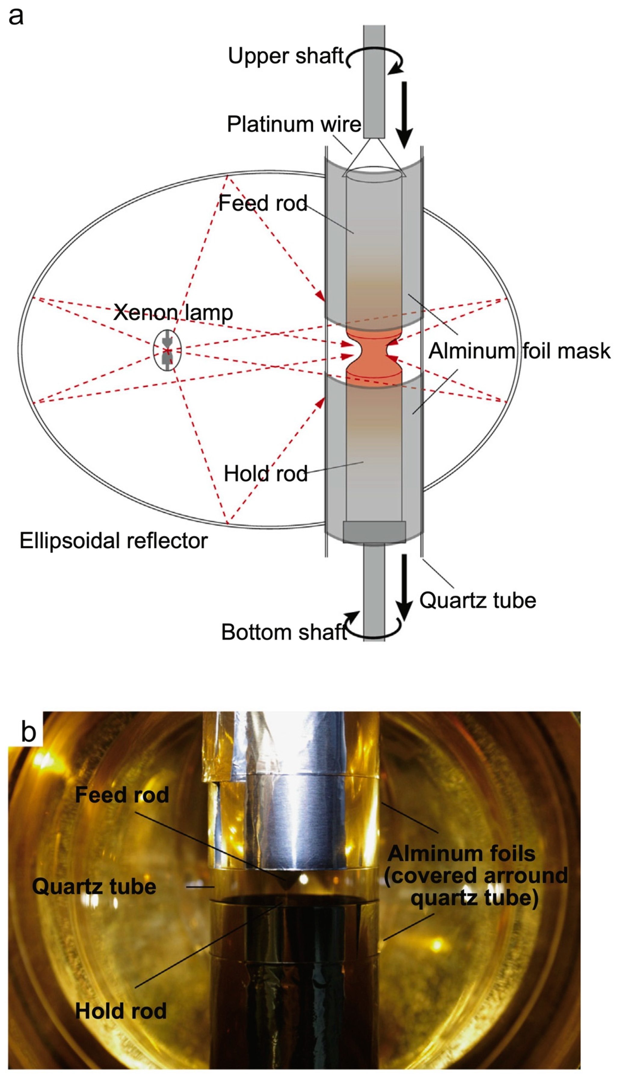
3.4. Effective Shielding of the Irradiation

Next, the author presents another improvement to obtain a sharper temperature gradient at the molten zone. Katsui et al. reported a simple but elegant method [104]. As shown in Figure 7, aluminum foils were wrapped around the outer surface of the quartz tube. The irradiation light can pass through only the centered 10 mm space between the upper and lower foils. These foils that shield from higher-angle irradiation result in a sharper temperature gradient at the interface. This yielded a stable and pseudo-congruent molten zone and finally succeeded in growing an incongruent material, BaTi2O5.
Setting a “cold trap” should contribute to the same effect [105]. The original motivation for introducing the cold trap was to catch up evaporated powders during the growth of ruthenate: the highly volatile RuO2 powders were deposited on the inside surface of the quartz tube if no trap was set. Since the evaporated black-color powders gradually lost the light intensity to the liquid area, the unstable zone prevented us from obtaining the crystals. By setting the trap inside the quartz tube at the around 3 cm upper position from the zone center, as shown in Figure 8 [105], the evaporated powders were deposited first on the surface of the trap rather than the quartz tube. Here, the trap remained cooler than the quartz tube by circulating water inside the trap. Setting the trap suppressed the light-blocking on the quartz tube. We finally obtained the crystals of the ferromagnetic oxide SrRuO3 for the original purpose of trapping the powders [105]. In addition, considering the previous paragraph about the “foil shielding”, it is indicated that the cold trap located in the upper parts of the liquid zone also acts as the irradiation shielding. Interestingly, what was developed for the original purpose had another effect. The author also mentions that the trap is easy to install because we only need to design/produce the trap and parallel water lines to the mirror cooling.

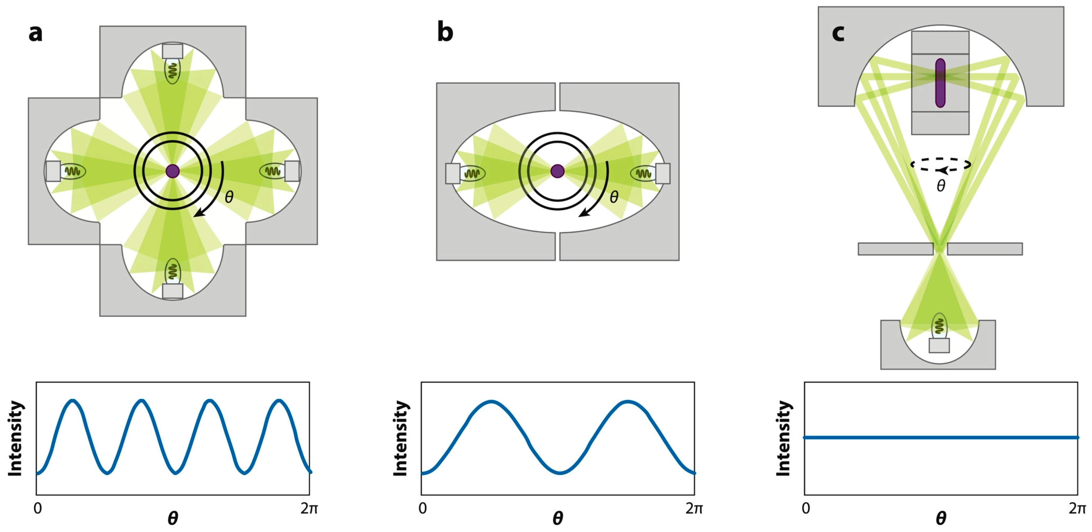
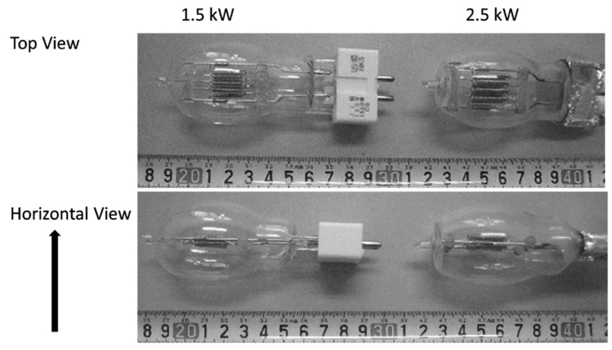
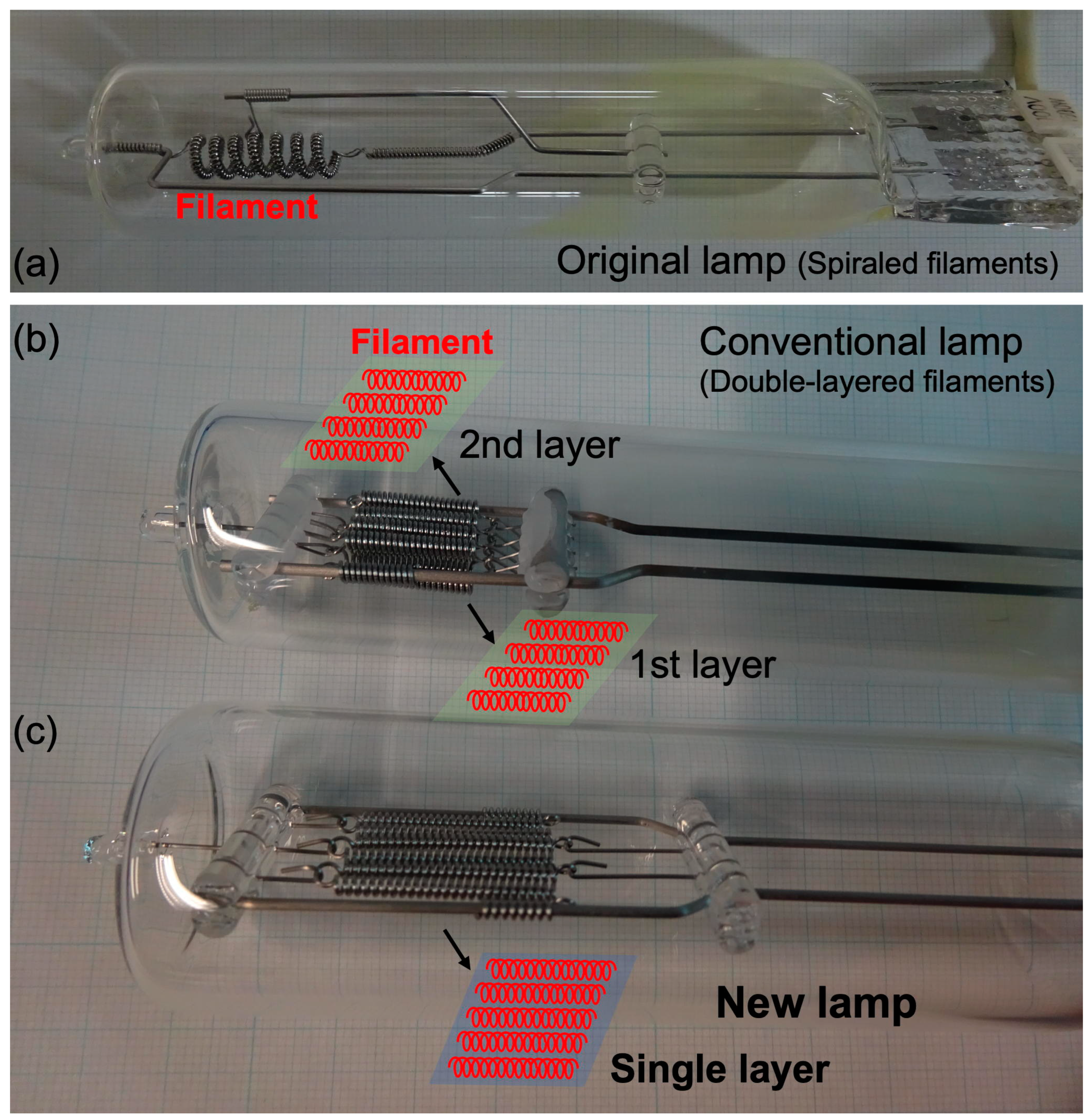
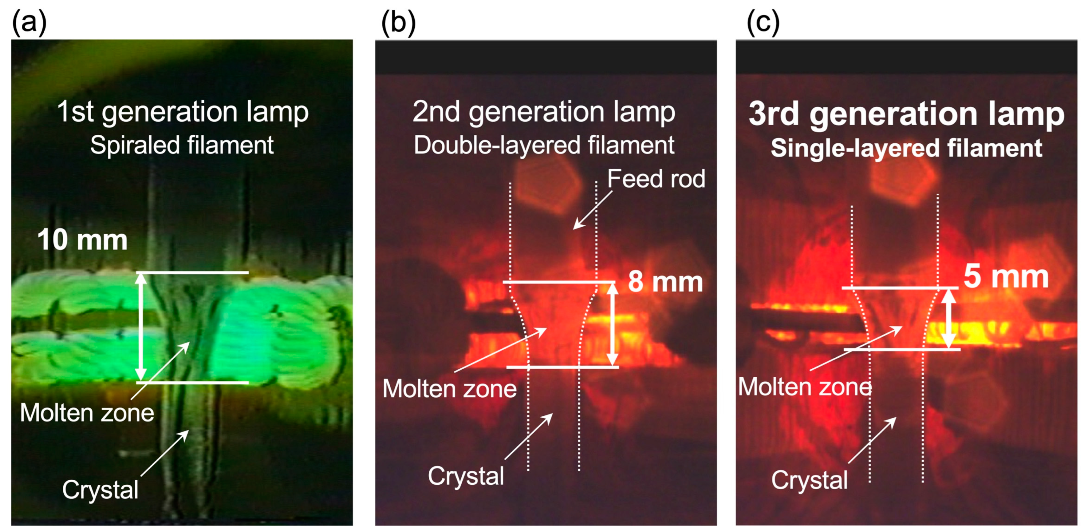
3.5. Shapes and Geometries of the Optical Lamps

Improving the lamp shape is also applicable to controlling the temperature profile at the interface. The principle of the floating zone with the elliptical mirror(s) is based on a simple assumption: the radiation that occurs as a “sizeless dot” at one focal point converges as another “dot” at the other focal point. However, since the filaments have their finite size with geometries, the converged point becomes broadened. That broader focus area makes the resultant temperature gradient broader. The modification of the filament shape has been examined to aim for a sharper temperature gradient. A systematic investigation was reported in 1998 for the large-size crystal growth of the high-Tc cuprates (La,Sr)2CuO4 [106]. They found that the simulation of the counter-mapped temperature profiles strongly depends on the orientations of the rectangular-shaped filaments with the same size, as shown in Figure 9 [106]. Also, a steeper temperature gradient was obtained with a smaller filament size. The gradient was also improved when the upper area of the mirror was shielded, as shown in Figure 10 [106]. They finally succeeded in the growth of the large crystals using the halogen lamps with small filaments combined with mirror shielding.
The author also mentions further insights from a systematic study performed by Hossain et al. on how the molten zone was affected by the filament size, mirror shape, and crystal diameter by the growth of a standard material, silicon [107]. Throughout the study, they designed a smaller size of the filaments, as shown in Figure 11 [107]. They concluded that a small filament and mirror with high eccentricity yield efficient light convergence to hold the stable zone. Interestingly, the stability can be evaluated by directly measuring the ratio between the minimum melting width at the zone and the diameter of the grown silicon crystal.
This section is closed by briefly tracking a “developing history” of how the molten zone becomes more stable by “downsizing” the filament sizes throughout the crystal growth of a layered perovskite ruthenate, Sr2RuO4 [108,109]. Keeping the molten zone stable is generally hard for ruthenates because of its low viscosity [30,31,32,36,105,108,109,110,111]. The first generation of the halogen lamp of the ruthenate growth had a “spiral” shaped filament as shown in Figure 12a. And the photo of the crystal growth using the spiral filament is presented in Figure 13a [108]. Here, the vertical length of the zone extends to about 10 mm [108], reflecting the total thickness of the spiraled filament. The next generation was produced with a flattened filament in early 1997. The filament had a double-layered structure (Figure 12b) with each layer forming an array of filaments. Since the layered filament with a total thickness of 6 mm was set horizontally at the focus point of the elliptical mirror, the molten zone was shrunk to typically 8 mm (Figure 13b). For the latest filament as shown in Figure 12c, the significant progress is that it forms a single layer with a thickness of 2 mm. Here, the total volume of the filament is reduced by 40%. We also noted that the required generating power to form the liquid zone of ruthenates over 2000 °C was still only 80% against fully available power. Finally, the molten zone was reduced to 5 mm (Figure 13c) and a stable molten zone was kept during the entire growth process, as the grown crystal had a 12 cm length with high quality, compared with the 7 cm length obtained using the second-generation filament [109].

4. Floating-Zone Furnaces with Laser Heating System

4.1. Development of the Laser-Heated Floating-Zone Furnaces

As well summarized by an article [85], several lasers have been examined for crystal growth. Recently, a new laser-heated floating-zone furnace was successfully assembled, where laser diodes were employed as a heat source (Figure 14) [112]. Here, the equivalent lasers with sufficient emission areas are equally located on a circle that each laser emits toward the feed rod set in the center of the circle. The features of laser emission are (i) highly directional light, (ii) high power, (iii) homogeneous density, and (iv) the controllability of the emission area from point-like narrow to wide regions. These are highly valuable when the laser facilities are equipped as the core part of the floating zone furnace because the growth circumstances are influenced as follows: (a) for the growth direction, a higher temperature gradient at the interface between the solidification and melting liquid; (b) highly homogeneous molten liquid along the in-plane azimuthal angle under the optimized laser-emission area. In other words, these can be interpretable as a further advanced version of the furnaces of which features are combined of both vertically and horizontally configured optical furnaces.
These advantages of both a high temperature gradient at the interface and homogeneity along the rotation axis allow us to apply the crystal growth to incongruent materials, as mentioned in [112]. For instance, the growth of typical incongruent materials such as multiferroic BiFeO3, the cuprate (La, Ba)2CuO4, and Y-type hexaferrite Ba2Co2Fe12O22 has succeeded using laser source heating [112,113]. Thus, the laser-heating method has a high potential for further crystal growth. Also, several further developments can be found using the laser source: one example is a “hybrid” furnace for the crystal growth of an incongruent oxide under a rather reducing temperature gradient, where four CO2 lasers and four halogen lamps are combined. The hybrid system enabled the successful production of an incongruent material terbium aluminum garnet (Tb3Al5O12) [114]. Another example is a laser-heated furnace where the crystals can be grown under extremely high pressure up to 675 bar [88], thanks to the laser property with an inherently well-directional beam. Also, a higher laser power system with 20 kW can be equipped and the diameter of the grown crystal β-Ga2O3 using the system reached 30 mm [115]. The size increase of β-Ga2O3 should be useful for its application as a wide-gap semiconductor for optoelectronic devices. Another example of the available large crystals using laser heating is the successful growth of R-Si-O systems that can be applied in scintillators used in gamma- and X-ray detectors [116].

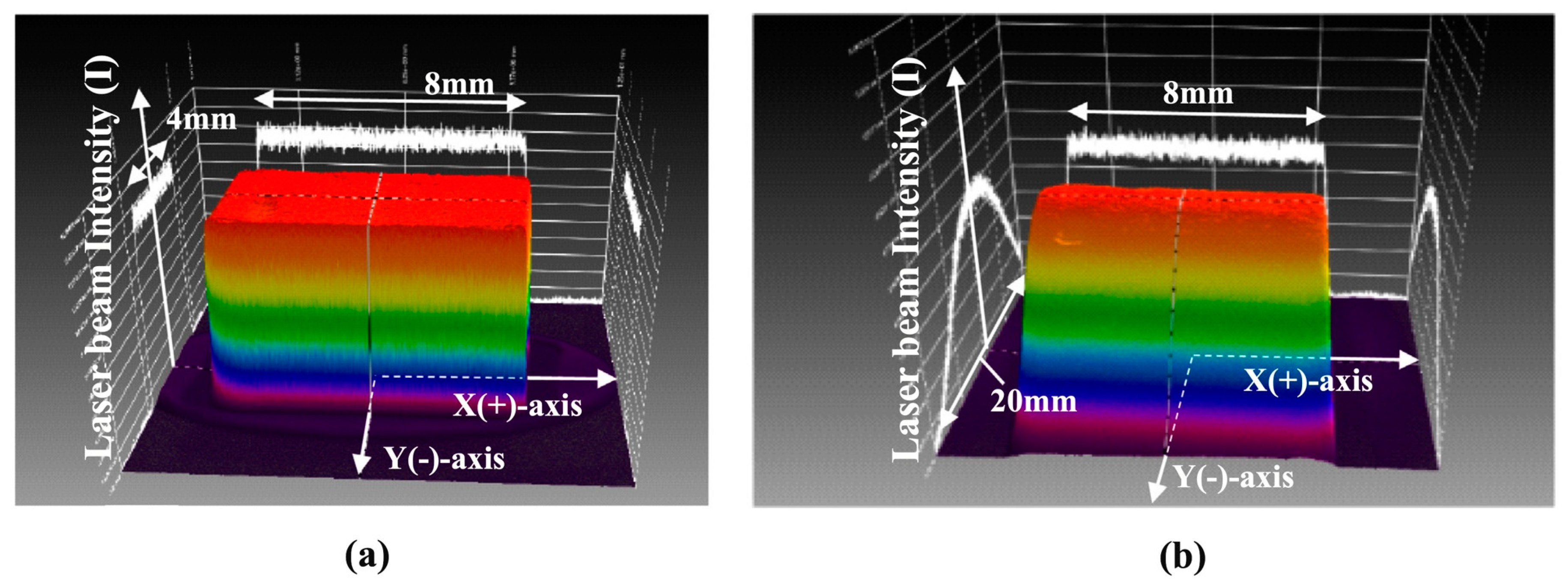
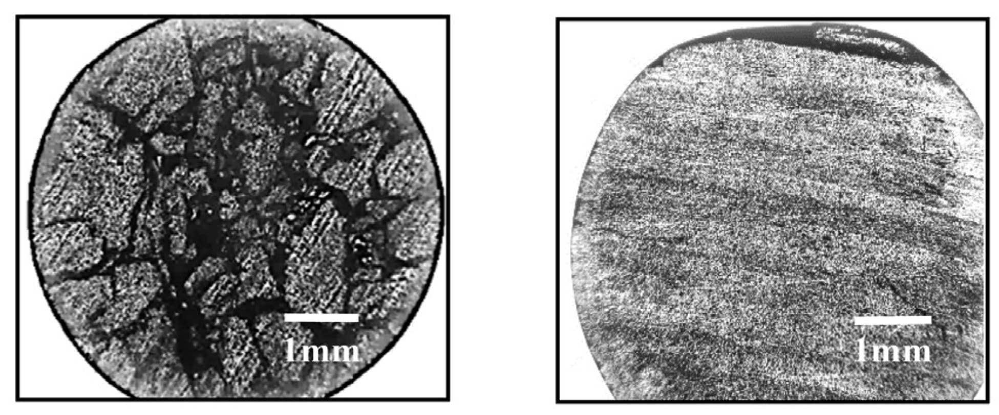
4.2. Modification of the Temperature Distribution Profile by Laser Emission

Further development of the laser intensity profile was performed by Kaneko and Tokura very recently [113]. Laser emission can make the zone narrower than that formed by the radiation from optical lamps, and the resultant interface between the solidified feed/grown crystals and the molten liquid can be sharply defined, as mentioned above. The “sharpness” can sometimes harmfully influence the cracking of the grown crystal because of the thermal stress. Therefore, a relaxing temperature gradient has been required for some materials, particularly oxides with a low thermal conductivity along the rods. One example was a hybrid system that combined optical lamps with lasers, as described above [114].
Another sophisticated approach is to modify the intensity profile of the laser by combining it with optics. To relax the temperature gradient, the vertical irradiation intensity along the growth direction has progressed from “flat” to “bell-shaped”; however, the horizontal profile was kept “originally flat” along the radial direction of the rod (Figure 15) [113]. The “modified” temperature gradient with the bell-shaped profile makes the temperature gradient mild. This is in contrast with the crystals grown under the original flat profile which were cracked by a too-sharp temperature gradient [113]. As shown in Figure 16, a multiferroic oxide TbMnO3 crystal has significant cracks under an unmodified “flat” profile; however, little cracks in the grown crystal are seen when the “modified bell-shape profile” is adopted [113]. Introducing modern laser technology to the floating-zone furnace enabled us to succeed in the crystal growth of quantum materials [117,118].

5. Concluding Remarks

The recent progress of the floating-zone furnaces for crystal growth is overviewed. The most crucial point of the crucible-free floating-zone method is to keep the molten zone stable, and many attempts have been examined the process and reported that the zone forms under the following circumstances: a steep temperature gradient at the liquid–solid interface along the growth direction, and a homogeneity of the molten liquid along the rotation axis. This article reviewed several recent achievements of floating-zone furnaces equipped with optical lamps or lasers as a heat source, as summarized in Table 1.
Attention has primarily focused on improving the temperature gradient in the optical lamp furnaces with horizontal configurations. This article took the topic of mirror tilting, shielding against irradiation, and the downsizing of the lamps. As an advantageous point, these improve the temperature gradient along the growth direction. On the other hand, it may affect the suppression of total power to the focal point. Therefore, we should be careful when we grow crystals with high melting points. For vertical-type furnaces, the outstanding advantage is the homogeneous molten liquid along the rotation axis. Since the advantage has been widely recognized, the vertical-type furnaces will be more popular in the near future. The laser-based furnaces have advantages for both cases of the temperature gradient and the homogeneous molten liquid in the practical setup, where the equivalent lasers with sufficient emission areas are equally located on a circle that each laser emits toward the feed rod set in the center of the circle. Furthermore, a “milder” intensity profile at the interface has been achieved to prevent cracks in the grown crystals, aiming to overcome the “disadvantage” of a too-sharp gradient formed by the original laser emission.
Looking over these improvements, although the author is afraid of missing other significant achievements, again, it is worth mentioning that these have been accomplished by introducing the latest technology at the time of each. Advancing laser technology is remarkable these days. It is promising that introducing further laser technology to the floating-zone furnace has a high potential to obtain larger crystals and to succeed in growing crystals that have had difficulties thus far. For further advancement, an example concept is to control the focal areas combined with optics during the growth. The “real-time” controlling of the focal area enables us to perform the growth operation of the entire growth process more smoothly from the necking at the start to the end of the growth through the subsequent stable growth of large crystals. For the optical mirror furnace, again, it is never “old fashioned”, because of the flexibility for the improvement. For instance, setting aluminum foils for shielding is simple but effective. Also, replacing the lamps with optimized filaments is a more practical and reliable approach, because nearly a thousand optical-lamp-based image furnaces have been installed worldwide, and they have sufficiently long lifetimes for operation once installed. Thus, our research interests toward the target materials should promote further progress of the furnaces, as it has in the past.
“Melt sufficiently, and then solidify steadily”, is the essence of crystal growth: in the floating-zone process, we never form the stable molten zone if the rod melting is poor. In addition, we cannot obtain the crystal if the molten zone cannot properly form the solidification under optimized conditions. Since the molten-liquid state of each material has intrinsic surface tension and viscosity, it still seems hard to find a “universal” procedure applicable to entire materials. Thus, crystal growth always faces challenges, particularly for novel materials like quantum materials. But, once the growth is succeeded, it opens a new window that the characterization of the grown bulk crystals unveils the fundamental and intrinsic properties. Here, properties should be intrinsic because the floating zone is again a “crucible-free” technique. These findings contribute to gaining knowledge of potential applications such as quantum computing, devices/sensors supporting an IoT society, and even energy fields that will be the basis of next-generation societies. Thus, returning to the Bridgman argument [1], the author emphasizes the importance of bulk crystal growth for novel materials based on contemporary concepts. The author believes that the advancing floating-zone technique continues to be a powerful tool for advancing material science.

Funding

This work is supported by the KAKENHI Grants-in-Aid for Scientific Research (Grant Nos. 18K0475, 21H01033, 22K19093, and 24K01461), the Core-to-Core Program (No. JPJSCCA20170002) from the Japan Society for the Promotion of Science (JSPS), and the JST-Mirai Program (Grant No. JPMJMI18A3).

Data Availability Statement

No new data were created or analyzed in this review.

Acknowledgments

The author acknowledges Andrew Peter Mackenzie, Yoshiteru Maeno, and Toshizo Fujita for the opportunities of crystal growth using the optical floating-zone furnaces and for the valuable information and discussion, Yoshio Kaneko for providing fruitful information about the laser floating-zone furnace, and Taichi Terashima, Shinya Uji, Dmitry Sokolov, Clifford Hicks, Takanobu Hiroto, Ayumi Kawaguchi, Takeshi Shimada, Akira Kamimura, John McArthur, Masahiro Ikeda, Noritaka Kimura, Naohiro Kaga, Yuta Maegawa, Tohru Nagasawa, Hideo Mishina, and Nobuyuki Ochiai for their kind support and fruitful discussion.

Conflicts of Interest

The author declares no conflicts of interest.

References

  1. Bridgman, P.W. Certain Physical Properties of Single Crystals of Tungsten, Antimony, Bismuth, Tellurium, Cadmium, Zinc, and Tin. Proc. Am. Acad. Arts Sci. 1925, 60, 305–383. [Google Scholar] [CrossRef]
  2. Lau, C.N.; Xia, F.; Cao, L. Emergent Quantum Materials. MRS Bull. 2020, 45, 340–347. [Google Scholar] [CrossRef]
  3. Alexandradinata, A.; Armitage, N.P.; Baydin, A.; Bi, W.; Cao, Y.; Changlani, H.J.; Chertkov, E.; da Silva Neto, E.H.; Delacretaz, L.; El Baggari, I.; et al. The Future of the Correlated Electron Problem. arXiv 2020, arXiv:2010.00584. [Google Scholar]
  4. Steglich, F.; Aarts, J.; Bredl, C.D.; Lieke, W.; Meschede, D.; Franz, W.; Schäfer, H. Superconductivity in the Presence of Strong Pauli Paramagnetism: CeCu2Si2. Phys. Rev. Lett. 1979, 43, 1892–1896. [Google Scholar] [CrossRef]
  5. Bednorz, J.G.; Miiller, K.A. Possible High Tc Superconductivity in the Ba-La-Cu-O System. Z. Phys. B Condens. Matter 1986, 64, 189–193. [Google Scholar] [CrossRef]
  6. Jérome, D.; Mazaud, A.; Ribault, M.; Bechgaard, K. Superconductivity in a Synthetic Organic Conductor (TMTSF)2PF6. J. Phys. Lett. 1980, 41, 95–98. [Google Scholar] [CrossRef]
  7. Tokura, Y. Correlated-Electron Physics in Transition-Metal Oxides. Phys. Today 2003, 56, 50–55. [Google Scholar] [CrossRef]
  8. Keimer, B.; Kivelson, S.A.; Norman, M.R.; Uchida, S.; Zaanen, J. From Quantum Matter to High-Temperature Superconductivity in Copper Oxides. Nature 2015, 518, 179–186. [Google Scholar] [CrossRef] [PubMed]
  9. Hasan, M.Z.; Moore, J.E. Three-Dimensional Topological Insulators. Annu. Rev. Condens. Matter Phys. 2011, 2, 55–78. [Google Scholar] [CrossRef]
  10. Ando, Y. Topological Insulator Materials. J. Phys. Soc. Jpn. 2013, 82, 102001. [Google Scholar] [CrossRef]
  11. Burkov, A.A. Topological Semimetals. Nat. Mater. 2016, 15, 1145–1148. [Google Scholar] [CrossRef] [PubMed]
  12. Armitage, N.P.; Mele, E.J.; Vishwanath, A. Weyl and Dirac Semimetals in Three-Dimensional Solids. Rev. Mod. Phys. 2018, 90, 015001. [Google Scholar] [CrossRef]
  13. Burkov, A.A. Weyl Metals. Annu. Rev. Condens. Matter Phys. 2018, 9, 359–378. [Google Scholar] [CrossRef]
  14. Bernevig, B.A.; Felser, C.; Beidenkopf, H. Progress and Prospects in Magnetic Topological Materials. Nature 2022, 603, 41–51. [Google Scholar] [CrossRef] [PubMed]
  15. Šmejkal, L.; González-Hernández, R.; Jungwirth, T.; Sinova, J. Crystal Time-Reversal Symmetry Breaking and Spontaneous Hall Effect in Collinear Antiferromagnets. Sci. Adv. 2020, 6, eaaz8809. [Google Scholar] [CrossRef]
  16. Šmejkal, L.; Sinova, J.; Jungwirth, T. Beyond Conventional Ferromagnetism and Antiferromagnetism: A Phase with Nonrelativistic Spin and Crystal Rotation Symmetry. Phys. Rev. X 2022, 12, 031042. [Google Scholar] [CrossRef]
  17. Šmejkal, L.; Sinova, J.; Jungwirth, T. Emerging Research Landscape of Altermagnetism. Phys. Rev. X 2022, 12, 040501. [Google Scholar] [CrossRef]
  18. Mazin, I. Altermagnetism Then and Now. Physics 2024, 17, 4. [Google Scholar] [CrossRef]
  19. Samarth, N. Quantum Materials Discovery from a Synthesis Perspective. Nat. Mater. 2017, 16, 1068–1076. [Google Scholar] [CrossRef]
  20. Pfann, W.G. Principles of Zone-Melting. JOM 1952, 4, 747–753. [Google Scholar] [CrossRef]
  21. Schmehr, J.L.; Wilson, S.D. Active Crystal Growth Techniques for Quantum Materials. Annu. Rev. Mater. Res. 2017, 47, 153–174. [Google Scholar] [CrossRef]
  22. Giustino, F.; Lee, J.H.; Trier, F.; Bibes, M.; Winter, S.M.; Valentí, R.; Son, Y.-W.; Taillefer, L.; Heil, C.; Figueroa, A.I.; et al. The 2021 Quantum Materials Roadmap. J. Phys. Mater. 2021, 3, 042006. [Google Scholar] [CrossRef]
  23. Tokura, Y. Quantum Materials at the Crossroads of Strong Correlation and Topology. Nat. Mater. 2022, 21, 971–973. [Google Scholar] [CrossRef] [PubMed]
  24. Šmejkal, L.; Mokrousov, Y.; Yan, B.; MacDonald, A.H. Topological Antiferromagnetic Spintronics. Nat. Phys. 2018, 14, 242–251. [Google Scholar] [CrossRef]
  25. He, Q.L.; Hughes, T.L.; Armitage, N.P.; Tokura, Y.; Wang, K.L. Topological Spintronics and Magnetoelectronics. Nat. Mater. 2022, 21, 15–23. [Google Scholar] [CrossRef] [PubMed]
  26. Christensen, D.V.; Staub, U.; Devidas, T.R.; Kalisky, B.; Nowack, K.C.; Webb, J.L.; Andersen, U.L.; Huck, A.; Broadway, D.A.; Wagner, K.; et al. 2024 Roadmap on Magnetic Microscopy Techniques and Their Applications in Materials Science. arXiv 2024, arXiv:2401.04793. [Google Scholar] [CrossRef]
  27. Keck, P.H.; Golay, M.J.E. Crystallization of Silicon from a Floating Liquid Zone. Phys. Rev. 1953, 89, 1297. [Google Scholar] [CrossRef]
  28. Emeis, R. Tiegelfreies Ziehen von Silicium-Einkristallen. Z. Naturforsch. A 1954, 9, 67–68. [Google Scholar] [CrossRef]
  29. Tanaka, I.; Yamane, K.; Kojima, H. Single Crystal Growth of Superconducting La2−xSrxCuO4 by the TSFZ Method. J. Cryst. Growth 1989, 96, 711–715. [Google Scholar] [CrossRef]
  30. Perry, R.S.; Maeno, Y. Systematic Approach to the Growth of High-Quality Single Crystals of Sr3Ru2O7. J. Cryst. Growth 2004, 271, 134–141. [Google Scholar] [CrossRef]
  31. Kikugawa, N.; Balicas, L.; Peter Mackenzie, A. Physical Properties of Single-Crystalline CaRuO3 Grown by a Floating-Zone Method. J. Phys. Soc. Jpn. 2009, 78, 014701. [Google Scholar] [CrossRef]
  32. Kikugawa, N.; Winfried Rost, A.; William Hicks, C.; John Schofield, A.; Peter Mackenzie, A. Ca3Ru2O7: Density Wave Formation and Quantum Oscillations in the Hall Resistivity. J. Phys. Soc. Jpn. 2010, 79, 024704. [Google Scholar] [CrossRef]
  33. Koohpayeh, S.; Wen, J.; Trump, B.; Broholm, C.; McQueen, T. Synthesis, Floating Zone Crystal Growth and Characterization of the Quantum Spin Ice Pr2Zr2O7 Pyrochlore. J. Cryst. Growth 2014, 402, 291–298. [Google Scholar] [CrossRef]
  34. Watauchi, S.; Matsuya, K.; Nagao, M.; Tanaka, I.; Kurosawa, S.; Yokota, Y.; Yoshikawa, A. Control of the Solid-Liquid Interface during Growth of a Ce-Doped Gd2Si2O7 Crystal by the Traveling Solvent Floating Zone Method. J. Cryst. Growth 2017, 468, 465–468. [Google Scholar] [CrossRef]
  35. Nakamura, S.; Maljuk, A.; Maruyama, Y.; Nagao, M.; Watauchi, S.; Hayashi, T.; Anzai, Y.; Furukawa, Y.; Ling, C.D.; Deng, G.; et al. Growth of LiCoO2 Single Crystals by the TSFZ Method. Cryst. Growth Des. 2019, 19, 415–420. [Google Scholar] [CrossRef]
  36. Bobowski, J.S.; Kikugawa, N.; Miyoshi, T.; Suwa, H.; Xu, H.-S.; Yonezawa, S.; Sokolov, D.A.; Mackenzie, A.P.; Maeno, Y. Improved Single-Crystal Growth of Sr2RuO4. Condens. Matter 2019, 4, 6. [Google Scholar] [CrossRef]
  37. Balbashov, A.M. Contemporary Apparatus for Single Crystals Growth of Oxide Compounds and Metals by Optical Floating Zone (FZ). Crystals 2019, 9, 487. [Google Scholar] [CrossRef]
  38. Berry, T.; Pressley, L.A.; Phelan, W.A.; Tran, T.T.; McQueen, T.M. Laser-Enhanced Single Crystal Growth of Non-Symmorphic Materials: Applications to an Eight-Fold Fermion Candidate. Chem. Mater. 2020, 32, 5827–5834. [Google Scholar] [CrossRef]
  39. Pressley, L.A.; Torrejon, A.; Phelan, W.A.; McQueen, T.M. Discovery and Single Crystal Growth of High Entropy Pyrochlores. Inorg. Chem. 2020, 59, 17251–17258. [Google Scholar] [CrossRef]
  40. Tomioka, Y.; Ito, T.; Maruyama, E.; Kimura, S.; Shindo, I. Magnetic and Electronic Properties of Single Crystals of Perovskite Nickelate Oxide LaNiO3 Prepared by the Laser Diode Floating Zone Method. J. Phys. Soc. Jpn. 2021, 90, 034704. [Google Scholar] [CrossRef]
  41. Berry, T.; Bernier, S.; Auffermann, G.; McQueen, T.M.; Adam Phelan, W. Laser Floating Zone Growth of SrVO3 Single Crystals. J. Cryst. Growth 2022, 583, 126518. [Google Scholar] [CrossRef]
  42. Pressley, L.A.; Sinha, M.; Vivanco, H.K.; Chamorro, J.; Das, S.; Ramesh, R.; McQueen, T.M. Optimization of PbTiO3 Single Crystals with Flux and Laser Floating Zone Method. Cryst. Growth Des. 2022, 22, 5629–5638. [Google Scholar] [CrossRef]
  43. Khandaker, M.R.; Maruyama, Y.; Nagao, M.; Watauchi, S.; Munakata, H.; Kanamura, K.; Tanaka, I. TSFZ Growth and Anisotropic Ionic Conductivity of Mg-Doped LiCoO2 Single Crystals. Cryst. Growth Des. 2023, 23, 5699–5704. [Google Scholar] [CrossRef]
  44. Zajíc, F.; Klejch, M.; Eliáš, A.; Klicpera, M.; Beitlerová, A.; Nikl, M.; Pospíšil, J. Nd:YAG Single Crystals Grown by the Floating Zone Method in a Laser Furnace. Cryst. Growth Des. 2023, 23, 2609–2618. [Google Scholar] [CrossRef] [PubMed]
  45. Amirkhizi, P.; Madre, M.A.; Dura, O.J.; Torres, M.A.; Sotelo, A.; Kovalevsky, A.; Rasekh, S. Effect of Laser Wavelength on the Thermoelectric Properties of Bi1.6Pb0.4Sr2Co2O8 Textured Ceramics Processed by LFZ. Ceram. Int. 2024, 50, 17924–17929. [Google Scholar] [CrossRef]
  46. Kaneko, Y.; Koda, T. New Developments in IIa–VIb (Alkaline-Earth Chalcogenide) Binary Semiconductors. J. Cryst. Growth 1988, 86, 72–78. [Google Scholar] [CrossRef]
  47. Koohpayeh, S.M. Single Crystal Growth by the Traveling Solvent Technique: A Review. Prog. Cryst. Growth Charact. Mater. 2016, 62, 22–34. [Google Scholar] [CrossRef]
  48. Amigó, M.L.; Maljuk, A.; Manna, K.; Stahl, Q.; Felser, C.; Hess, C.; Wolter, A.U.B.; Geck, J.; Seiro, S.; Büchner, B. Laser-Assisted Floating Zone Growth of BaFe2S3 Large-Sized Ferromagnetic-Impurity-Free Single Crystals. Crystals 2021, 11, 758. [Google Scholar] [CrossRef]
  49. Kaneko, Y.; Morimoto, K.; Koda, T. Optical Properties of Alkaline-Earth Chalcogenides. I. Single Crystal Growth and Infrared Reflection Spectra Due to Optical Phonons. J. Phys. Soc. Jpn. 1982, 51, 2247–2254. [Google Scholar] [CrossRef]
  50. Souptel, D.; Behr, G.; Ivanenko, L.; Vinzelberg, H.; Schumann, J. Floating Zone Growth and Characterization of Semiconducting Ru2Si3 Single Crystals. J. Cryst. Growth 2002, 244, 296–304. [Google Scholar] [CrossRef]
  51. Souptel, D.; Leithe-Jasper, A.; Löser, W.; Schnelle, W.; Borrmann, H.; Behr, G. Floating Zone Growth and Characterization of Pr5Si3 Single Crystals. J. Cryst. Growth 2004, 273, 311–319. [Google Scholar] [CrossRef]
  52. Behr, G.; Löser, W.; Souptel, D.; Fuchs, G.; Mazilu, I.; Cao, C.; Köhler, A.; Schultz, L.; Büchner, B. Crystal Growth of Rare Earth-Transition Metal Borocarbides and Silicides. J. Cryst. Growth 2008, 310, 2268–2276. [Google Scholar] [CrossRef]
  53. Cao, C.; Blum, C.G.F.; Löser, W. Floating Zone Crystal Growth of Lu2PdSi3 Silicide. J. Cryst. Growth 2014, 401, 593–595. [Google Scholar] [CrossRef]
  54. Huber, N.; Leeb, V.; Bauer, A.; Benka, G.; Knolle, J.; Pfleiderer, C.; Wilde, M.A. Quantum Oscillations of the Quasiparticle Lifetime in a Metal. Nature 2023, 621, 276–281. [Google Scholar] [CrossRef]
  55. Huber, N.; Mishra, S.; Sheikin, I.; Alpin, K.; Schnyder, A.P.; Benka, G.; Bauer, A.; Pfleiderer, C.; Wilde, M.A. Fermi Surface of the Chiral Topological Semimetal CoSi. Phys. Rev. B 2024, 109, 205115. [Google Scholar] [CrossRef]
  56. Iga, F.; Shimizu, N.; Takabatake, T. Single Crystal Growth and Physical Properties of Kondo Insulator YbB12. J. Magn. Magn. Mater. 1998, 177, 337–338. [Google Scholar] [CrossRef]
  57. Otani, S.; Korsukova, M.M.; Mitsuhashi, T. Preparation of HfB2 and ZrB2 Single Crystals by the Floating-Zone Method. J. Cryst. Growth 1998, 186, 582–586. [Google Scholar] [CrossRef]
  58. Otani, S.; Ohsawa, T. Floating Zone Growth and High-Temperature Hardness of CrB2 Single Crystals. J. Cryst. Growth 1999, 200, 472–475. [Google Scholar] [CrossRef]
  59. Otani, S.; Korsukova, M.M.; Mitsuhashi, T.; Kieda, N. Floating Zone Growth and High-Temperature Hardness of YB4 and YB6 Single Crystals. J. Cryst. Growth 2000, 217, 378–382. [Google Scholar] [CrossRef]
  60. Tanaka, T.; Sato, A. Floating Zone Crystal Growth and Structure Analysis of a Novel ScB19 Family Compound, ScB19+xSiy. J. Solid State Chem. 2001, 160, 394–400. [Google Scholar] [CrossRef]
  61. Otani, S.; Segawa, H.; Ohashi, N. Floating Zone Growth of Cerium Tetra-Boride Crystals. J. Ceram. Soc. Jpn. 2014, 122, 192–194. [Google Scholar] [CrossRef]
  62. Sussardi, A.; Tanaka, T.; Khan, A.U.; Schlapbach, L.; Mori, T. Enhanced Thermoelectric Properties of Samarium Boride. J. Mater. 2015, 1, 196–204. [Google Scholar] [CrossRef]
  63. Brunt, D.; Ciomaga Hatnean, M.; Petrenko, O.A.; Lees, M.R.; Balakrishnan, G. Single-Crystal Growth of Metallic Rare-Earth Tetraborides by the Floating-Zone Technique. Crystals 2019, 9, 211. [Google Scholar] [CrossRef]
  64. Precht, W.; Hollox, G.E. A Floating Zone Technique for the Growth of Carbide Single Crystals. J. Cryst. Growth 1968, 3–4, 818–823. [Google Scholar] [CrossRef]
  65. Otani, S.; Tanaka, T.; Ishizawa, Y. Preparation of NbCx Single Crystals by a Floating Zone Technique. J. Cryst. Growth 1983, 62, 211–218. [Google Scholar] [CrossRef]
  66. Otani, S.; Honma, S.; Tanaka, T.; Ishizawa, Y. Preparation of TiCx Single Crystals with Maximum Carbon Content by a Floating Zone Technique. J. Cryst. Growth 1983, 61, 1–7. [Google Scholar] [CrossRef]
  67. Hou, Y.; Otani, S.; Tanaka, T.; Ishizawa, Y. Preparation of Vanadium Carbide Single Crystals by a Floating Zone Technique. J. Cryst. Growth 1984, 68, 733–740. [Google Scholar] [CrossRef]
  68. Tanaka, T.; Otani, S.; Ishizawa, Y. Floating-Zone Crystal Growth of WC. J. Mater. Sci. 1988, 23, 665–669. [Google Scholar] [CrossRef]
  69. Takeya, H.; Hirano, T.; Kadowaki, K. Single Crystal Growth of Quaternary Superconductor YNi2B2C by a Floating Zone Method. Phys. C Supercond. 1996, 256, 220–226. [Google Scholar] [CrossRef]
  70. Straker, M.; Chauhan, A.; Sinha, M.; Phelan, W.A.; Chandrashekhar, M.V.S.; Hemker, K.J.; Marvel, C.; Spencer, M. Growth of High Purity Zone-Refined Boron Carbide Single Crystals by Laser Diode Floating Zone Method. J. Cryst. Growth 2020, 543, 125700. [Google Scholar] [CrossRef]
  71. Hirano, T. Improvement of Room Temperature Ductility of Stoichiometric Ni3Al by Unidirectional Solidification. Acta Metall. Mater. 1990, 38, 2667–2671. [Google Scholar] [CrossRef]
  72. Hirano, T.; Mawari, T. Unidirectional Solidification of Ni3Al by a Floating Zone Method. Acta Metall. Mater. 1993, 41, 1783–1789. [Google Scholar] [CrossRef]
  73. Subramanian, R.; Higuchi, M.; Dieckman, R. Growth of Nickel Aluminate Single Crystals by the Floating Zone Method. J. Cryst. Growth 1994, 143, 311–316. [Google Scholar] [CrossRef]
  74. Xu, Y.; Löser, W.; Behr, G.; Frontzek, M.; Tang, F.; Büchner, B.; Liu, L. Crystal Growth of the Pr2PdSi3 Intermetallic Compound. J. Cryst. Growth 2010, 312, 1992–1996. [Google Scholar] [CrossRef]
  75. Cao, C.; Löser, W.; Behr, G.; Klingeler, R.; Leps, N.; Vinzelberg, H.; Büchner, B. Single Crystal Growth of Eu2CuSi3 Intermetallic Compound by the Floating-Zone Method. J. Cryst. Growth 2011, 318, 1009–1012. [Google Scholar] [CrossRef]
  76. Cao, C.; Deppe, M.; Behr, G.; Löser, W.; Wizent, N.; Kataeva, O.; Büchner, B. Single Crystal Growth of the CeCu2Si2 Intermetallic Compound by a Vertical Floating Zone Method. Cryst. Growth Des. 2011, 11, 431–435. [Google Scholar] [CrossRef]
  77. Neubauer, A.; Jonietz, F.; Meven, M.; Georgii, R.; Brandl, G.; Behr, G.; Böni, P.; Pfleiderer, C. Optical Floating Zone Growth of High-Quality Cu2MnAl Single Crystals. Nucl. Instrum. Methods Phys. Res. A 2012, 688, 66–74. [Google Scholar] [CrossRef]
  78. Xu, Y.; Liu, L.; Löser, W.; Frontzek, M. Vertical Floating Zone Crystal Growth of R2PdSi3 Intermetallic Compounds (R = Pr and Nd). Adv. Mat. Res. 2013, 774–776, 720–724. [Google Scholar]
  79. Hermann, R.; Gerbeth, G.; Priede, J. Magnetic Field Controlled Floating-Zone Single Crystal Growth of Intermetallic Compounds. Eur. Phys. J. Spec. Top. 2013, 220, 227–241. [Google Scholar] [CrossRef]
  80. Avers, K.E.; Nguyen, M.D.; Scott, J.W.; Zimmerman, A.M.; Thomas, S.M.; Rosa, P.F.S.; Bauer, E.D.; Thompson, J.D.; Halperin, W.P. Electron-Beam Floating-Zone Refined UCoGe. Phys. Rev. Mater. 2021, 5, 054803. [Google Scholar] [CrossRef]
  81. Koohpayeh, S.M.; Fort, D.; Abell, J.S. The Optical Floating Zone Technique: A Review of Experimental Procedures with Special Reference to Oxides. Prog. Cryst. Growth Charact. Mater. 2008, 54, 121–137. [Google Scholar] [CrossRef]
  82. Dabkowska, H.A.; Dabkowski, A.B. Crystal Growth of Oxides by Optical Floating Zone Technique. In Springer Handbook of Crystal Growth; Dhanaraj, G., Byrappa, K., Prasad, V., Dudley, M., Eds.; Springer: Berlin/Heidelberg, Germany, 2010; pp. 367–391. ISBN 9783540747611. [Google Scholar]
  83. Floating Zone Growth of Oxides and Metallic Alloys. In Handbook of Crystal Growth, 2nd ed.; Rudolph, P. (Ed.) Elsevier: Boston, MA, USA, 2015; pp. 281–329. ISBN 9780444633033. [Google Scholar]
  84. Gille, P.; Grin, Y. Crystal Growth of Intermetallics; Gille, P., Grin, Y., Eds.; Walter de Gruyter GmbH: Berlin, Germany, 2019; ISBN 9783110495843. [Google Scholar]
  85. Rey-García, F.; Ibáñez, R.; Angurel, L.A.; Costa, F.M.; de la Fuente, G.F. Laser Floating Zone Growth: Overview, Singular Materials, Broad Applications, and Future Perspectives. Crystals 2020, 11, 38. [Google Scholar] [CrossRef]
  86. Pistawala, N.; Rout, D.; Saurabh, K.; Bag, R.; Karmakar, K.; Harnagea, L.; Singh, S. Crystal Growth of Quantum Materials: A Review of Selective Materials and Techniques. Bull. Mater. Sci. 2021, 45, 10. [Google Scholar] [CrossRef]
  87. Neubauer, A.; Boeuf, J.; Bauer, A.; Russ, B.; Löhneysen, H.v.; Pfleiderer, C. Ultra-High Vacuum Compatible Image Furnace. Rev. Sci. Instrum. 2011, 82, 013902. [Google Scholar] [CrossRef] [PubMed]
  88. Schmehr, J.L.; Aling, M.; Zoghlin, E.; Wilson, S.D. High-Pressure Laser Floating Zone Furnace. Rev. Sci. Instrum. 2019, 90, 043906. [Google Scholar] [CrossRef]
  89. Nagai, I.; Shirakawa, N.; Ikeda, S.-I.; Iwasaki, R.; Nishimura, H.; Kosaka, M. Highest Conductivity Oxide SrMoO3 Grown by a Floating-Zone Method under Ultralow Oxygen Partial Pressure. Appl. Phys. Lett. 2005, 87, 024105. [Google Scholar] [CrossRef]
  90. De La Rue, R.E.; Halden, F.A. Arc-Image Furnace for Growth of Single Crystals. Rev. Sci. Instrum. 1960, 31, 35–38. [Google Scholar] [CrossRef]
  91. Souptel, D.; Löser, W.; Behr, G. Vertical Optical Floating Zone Furnace: Principles of Irradiation Profile Formation. J. Cryst. Growth 2007, 300, 538–550. [Google Scholar] [CrossRef]
  92. Bednorz, J.; Arend, H. A 1 KW Mirror Furnace for Growth of Refractory Oxide Single Crystals by a Floating-Zone Technique. J. Cryst. Growth 1984, 67, 660–662. [Google Scholar] [CrossRef]
  93. Dold, P.; Cröll, A.; Benz, K.W. Floating-Zone Growth of Silicon in Magnetic Fields I. Weak Static Axial Fields. J. Cryst. Growth 1998, 183, 545553. [Google Scholar] [CrossRef]
  94. Sarker, A.R.; Watauchi, S.; Nagao, M.; Watanabe, T.; Shindo, I.; Tanaka, I. Effects of Tilting Mirrors on the Solid–Liquid Interface during Floating Zone Growth Using Tilting-Mirror-Type Infrared-Heating Image Furnace. J. Cryst. Growth 2010, 312, 2008–2011. [Google Scholar] [CrossRef]
  95. Higuchi, M.; Hosokawa, T.; Kimura, S. Growth of Rutile Single Crystals by Floating Zone Method. J. Cryst. Growth 1991, 112, 354–358. [Google Scholar] [CrossRef]
  96. Higuchi, M.; Kodaira, K. Solid-Liquid Interface Shapes in the Floating Zone Growth of Rutile Single Crystals. Mater. Res. Bull. 1994, 29, 545–550. [Google Scholar] [CrossRef]
  97. Sarker, M.A.R.; Watauchi, S.; Nagao, M.; Watanabe, T.; Shindo, I.; Tanaka, I. Reduced Etch Pit Density of Rutile (TiO2) Single Crystals by Growth Using a Tilting-Mirror-Type Infrared Heating Image Furnace. Cryst. Growth Des. 2010, 10, 3929–3930. [Google Scholar] [CrossRef]
  98. Sarker, A.R.; Watauchi, S.; Nagao, M.; Watanabe, T.; Shindo, I.; Tanaka, I. Effects of the Diameter of Rutile (TiO2) Single Crystals Grown Using Tilting-Mirror-Type Infrared Heating Image Furnace on Solid–Liquid Interface and Etch Pit Density. J. Cryst. Growth 2011, 317, 135–138. [Google Scholar] [CrossRef]
  99. Sarker, A.R. Growth of Large Size Lithium Niobate Single Crystals of High Quality by Tilting-Mirror-Type Floating Zone Method. Mater. Res. 2016, 19, 505–512. [Google Scholar] [CrossRef]
  100. Hossain, M.M.; Watauchi, S.; Nagao, M.; Tanaka, I. Effects of Tilt Angle of Mirror-Lamp System on Shape of Solid-Liquid Interface of Silicon Melt during Floating Zone Growth Using Infrared Convergent Heating. J. Cryst. Growth 2016, 433, 24–30. [Google Scholar] [CrossRef]
  101. Parvin, R.; Maruyama, Y.; Nagao, M.; Watauchi, S.; Tanaka, I. Effects of the Mirror Tilt Angle on the Growth of LiCoO2 Single Crystals by the Traveling Solvent Floating Zone (TSFZ) Technique Using a Tilting-Mirror-Type Image Furnace. Cryst. Growth Des. 2020, 20, 3413–3416. [Google Scholar] [CrossRef]
  102. Noda, N.; Watauchi, S.; Maruyama, Y.; Nagao, M.; Kakimoto, K.; Tanaka, I. Investigating the Combined Effects of Mirror Tilting and Position on Rutile Crystal Growth Using the Infrared Convergent-Heating Floating Zone Method. J. Cryst. Growth 2021, 571, 126257. [Google Scholar] [CrossRef]
  103. Noda, N.; Watauchi, S.; Maruyama, Y.; Nagao, M.; Hossain, M.M.; Yokota, Y.; Kurosawa, S.; Yoshikawa, A.; Kakimoto, K.; Tanaka, I. Effects of Lamp Filament Alignment, Mirror–Lamp System Position, and Downward Tilt during Growth of Lanthanum- and Cerium-Doped Gadolinium Pyrosilicate Crystal Using Optical Floating Zone Method. SSRN Electron. J. 2023. [Google Scholar] [CrossRef]
  104. Katsui, H.; Shiga, K.; Tu, R.; Goto, T. Crystal Growth of BaTi2O5 by the Floating Zone Method. J. Cryst. Growth 2013, 384, 66–70. [Google Scholar] [CrossRef]
  105. Kikugawa, N.; Baumbach, R.; Brooks, J.S.; Terashima, T.; Uji, S.; Maeno, Y. Single-Crystal Growth of a Perovskite Ruthenate SrRuO3 by the Floating-Zone Method. Cryst. Growth Des. 2015, 15, 5573–5577. [Google Scholar] [CrossRef]
  106. Lee, C.-H.; Kaneko, N.; Hosoya, S.; Kurahashi, K.; Wakimoto, S.; Yamada, K.; Endoh, Y. Growth of Large Single Crystals Using the Improved Lamp-Image Floating-Zone Furnace: Application To. Supercond. Sci. Technol. 1998, 11, 891. [Google Scholar] [CrossRef]
  107. Hossain, M.M.; Watauchi, S.; Nagao, M.; Tanaka, I. Effects of Growth Parameters on Silicon Molten Zone Formed by Infrared Convergent-Heating Floating Zone Method. J. Cryst. Growth 2017, 459, 105–111. [Google Scholar] [CrossRef]
  108. Maeno, Y.; Rice, T.M.; Sigrist, M. The Intriguing Superconductivity of Strontium Ruthenate. Phys. Today 2001, 54, 42–47. [Google Scholar] [CrossRef]
  109. Kikugawa, N.; Sokolov, D.A.; Nagasawa, T.; Mackenzie, A.P. Single-Crystal Growth of Sr2RuO4 by the Floating-Zone Method Using an Infrared Image Furnace with Improved Halogen Lamps. Crystals 2021, 11, 392. [Google Scholar] [CrossRef]
  110. Mao, Z.Q.; Maeno, Y.; Fukazawa, H. Crystal Growth of Sr2RuO4. Mater. Res. Bull. 2000, 35, 1813–1824. [Google Scholar] [CrossRef]
  111. Ikeda, S.I.; Azuma, U.; Shirakawa, N.; Nishihara, Y.; Maeno, Y. Bulk Single-Crystal Growth of Strontium Ruthenates by a Floating-Zone Method. J. Cryst. Growth 2002, 237–239, 787–791. [Google Scholar] [CrossRef]
  112. Ito, T.; Ushiyama, T.; Yanagisawa, Y.; Tomioka, Y.; Shindo, I.; Yanase, A. Laser-Diode-Heated Floating Zone (LDFZ) Method Appropriate to Crystal Growth of Incongruently Melting Materials. J. Cryst. Growth 2013, 363, 264–269. [Google Scholar] [CrossRef]
  113. Kaneko, Y.; Tokura, Y. Floating Zone Furnace Equipped with a High Power Laser of 1 kW Composed of Five Smart Beams. J. Cryst. Growth 2020, 533, 125435. [Google Scholar] [CrossRef]
  114. Geho, M.; Sekijima, T.; Fujii, T. Growth of Terbium Aluminum Garnet (Tb3Al5O12; TAG) Single Crystals by the Hybrid Laser Floating Zone Machine. J. Cryst. Growth 2004, 267, 188–193. [Google Scholar] [CrossRef]
  115. Ito, T.; Tomioka, Y.; Rackerseder, F.; Traub, M.; Hoffmann, D. Growth of β-Ga2O3 Crystal with a Diameter of 30 mm by Laser-Diode-Heated Floating Zone (LDFZ) Method. J. Cryst. Growth 2024, 634, 127673. [Google Scholar] [CrossRef]
  116. Hatnean, V.C.C.; Pui, A.; Simonov, A.; Hatnean, M.C. Crystal Growth of the RSiO Compounds (R = Dy, Ho, and Er) by the Floating Zone Method Using a Laser-Diode-Heated Furnace. Crystals 2023, 13, 1687. [Google Scholar] [CrossRef]
  117. Kikugawa, N.; Terashima, T.; Kato, T.; Hayashi, M.; Yamaguchi, H.; Uji, S. Bulk Physical Properties of a Magnetic Weyl Semimetal Candidate NdAlGe Grown by a Laser Floating-Zone Method. Inorganics 2023, 11, 20. [Google Scholar] [CrossRef]
  118. Kikugawa, N.; Kato, T.; Hayashi, M.; Yamaguchi, H. Single-Crystal Growth of a Cubic Laves-Phase Ferromagnet HoAl2 by a Laser Floating-Zone Method. Crystals 2023, 13, 760. [Google Scholar] [CrossRef]
Figure 1. Illustration of the floating-zone processes. Here, the red arrows represent the light conversion to the focal point. (a) Local heating to the feed rod for melting. (b) Forming the molten zone. (c) Growing the single crystal by pulling both the feed and seed rods.
Crystals 14 00552 g001
Figure 2. Illustration of the cross-sectional floating-zone furnaces equipped with (a) double elliptical mirrors and optical lamps, and (b) laser facility.
Crystals 14 00552 g002
Figure 3. Schematic drawings from the top view of the optical-lamp type floating-zone furnaces. (a) Four-mirror horizontal geometry with four lamps. (b) Two-mirror horizontal geometry with two lamps. (c) Two-mirror vertical geometry with a single lamp. Below each schematic graph represents the optical power intensity profile at the growth position along rotation within the transverse plane. Figures (ac) are reprinted from [21], with the permission of Annual Reviews.
Crystals 14 00552 g003
Figure 4. Schematic cross-sectional drawing of the vertical floating-zone furnace equipped with a single mirror. The figure is reprinted from [92], with the permission of Elsevier.
Crystals 14 00552 g004
Figure 5. (a) Schematic drawings of the vertical floating-zone furnace equipped with double mirrors. The inset illustrates the crystal growth with a typical light-intensity profile. (b) The cross-sectional optical configurations of the vertical-type furnace. The figure is reprinted from [91], with the permission of Elsevier.
Crystals 14 00552 g005
Figure 6. Schematic cross-sectional illustration of the optical floating-zone furnace with tilted mirrors. The figure is reprinted from [94], with the permission of Elsevier.
Crystals 14 00552 g006
Figure 7. Schematic drawing (a) and picture (b) of the floating-zone furnace with aluminum foil for shielding. The figure is reprinted from [104], with the permission of Elsevier.
Crystals 14 00552 g007
Figure 8. Photo of the floating-zone furnace with a cold trap. The figure is reprinted from [105], with the permission of the American Chemical Society.
Crystals 14 00552 g008
Figure 9. (a) Schematic drawing of an elliptical mirror of the floating-zone furnace. (bd) Calculated counter maps of the light distribution under different orientations of a rectangular-shaped filament. The figure is reprinted from [106], with the permission of the Institute of Physics.
Crystals 14 00552 g009
Figure 10. Schematic drawing of the shielding area of the mirror depicted by gray color. The figure is reprinted from [106], with the permission of the Institute of Physics.
Crystals 14 00552 g010
Figure 11. Photo of different sizes of the lamps. The figure is reprinted from [107], with the permission of Elsevier.
Crystals 14 00552 g011
Figure 12. Photos of the halogen lamps for the growth of Sr2RuO4. (a) The first-generation lamp with a spiral filament. (b) The second-generation lamp with a double-layered flat filament. (c) The latest lamp with a single-layered flat filament. Figures are reprinted from [109].
Crystals 14 00552 g012
Figure 13. Photos of the crystal growth of Sr2RuO4 with (a) the first-generation lamp with a spiral filament. (b) the second-generation lamp with a double-layered flat filament. (c) the latest lamp with a single-layered flat filament. Figure (a) is reproduced from [108], with the permission of the American Institute of Physics. Figures (b,c) are reprinted from [109].
Crystals 14 00552 g013
Figure 14. Photo of laser-diode-heated floating-zone furnace. The upper photo (a) represents the core area for the growth, while the lower photo (b) shows the whole furnace with PC system for operation. The figures are reprinted from [112], with the permission of Elsevier.
Crystals 14 00552 g014
Figure 15. Irradiation intensity profile of the laser. (a) The horizontal profile is kept “originally flat” along the radial direction of the rod. (b) The vertical irradiation intensity along the growth direction has progressed from “flat” to “bell-shaped” to relax the temperature gradient. The figures are reprinted from [113], with the permission of Elsevier.
Crystals 14 00552 g015
Figure 16. Cross-section pictures of the grown TbMnO3 crystals by the laser-heated floating-zone furnace. The left picture with many cracks represents the growth under the original “flat” temperature profile along the growth direction, whereas the right one with little cracks represents the growth under the improved “bell-shaped” temperature profile. The figures are reprinted from [113], with the permission of Elsevier.
Crystals 14 00552 g016
Table 1. Summary of the recent progress of the floating-zone furnaces aiming for the stable molten zone.
TechniqueSectionImprovementReferences
Optical lamp with vertical configuration3.2Homogeneous liquid[37,52,91,92,93]
Tilted mirror3.3Temperature gradient[94,97,98,99,100,101,102,103]
Irradiation shielding3.4Temperature gradient[104,105]
Lamp shape and geometries3.5Temperature gradient[106,107,109]
Laser heating4.1Temperature gradient and homogeneous liquid[112]
Laser heating with modified temperature distribution4.2“Milder” temperature gradient and homogeneous liquid[113]
Disclaimer/Publisher’s Note: The statements, opinions and data contained in all publications are solely those of the individual author(s) and contributor(s) and not of MDPI and/or the editor(s). MDPI and/or the editor(s) disclaim responsibility for any injury to people or property resulting from any ideas, methods, instructions or products referred to in the content.

