Article

Preparation of Reduced Graphene Oxide Films with High and Uniform Thickness for Electromagnetic Interference Shielding

1
CAS Key Laboratory of Carbon Materials, Institute of Coal Chemistry, Chinese Academy of Sciences, Taiyuan 030001, China
2
University of Chinese Academy of Sciences, Beijing 100049, China
*
Authors to whom correspondence should be addressed.
Crystals 2024, 14(4), 322; https://doi.org/10.3390/cryst14040322
Submission received: 5 March 2024 / Revised: 26 March 2024 / Accepted: 28 March 2024 / Published: 29 March 2024
(This article belongs to the Section Inorganic Crystalline Materials)

Abstract

:
Reduced graphene films have attracted widespread commercial interest due to high electrical conductivity toward (EMI) shielding. At present, the preparation path of reduced graphene film is to use graphene oxide (GO) as the raw material through self-assembly and high-temperature heat treatment. However, the thickness of reduced graphene films is not high and uniform because of the higher mobility of the graphene oxide slurry, which destroys the reliability of the membrane in the field of electromagnetic interference shielding. Here, we propose the use of sodium carboxymethyl cellulose (CMC) to increase the viscosity of graphene oxide to prepare reduced graphene films with high and uniform thickness. After modification with sodium carboxymethyl cellulose, the EMI shielding effectiveness (EMI SE) of reduced graphene oxide films stabilized at 91–96 dB at 8–12 GHz, which is higher than pure graphene films. Meanwhile, the addition of CMC does not affect the structure of reduced graphene films. This work broadens the application of reduced graphene films in electromagnetic shielding.

1. Introduction

With the development of wireless communication and 5G electronic devices, electromagnetic radiation and interference (EMI) have become increasingly important issues, which can seriously hamper the proper functioning of equipment and even threaten human health [1,2]. At present, multi-material applications have been developed for electromagnetic protection, including lightweight aerogel, metal sheets, foams, and freestanding film [3,4,5,6].
In these materials, metal sheets and foams are less reliable in application due to high bulk density and poor corrosion resistance. On the contrary, the films have a broad application prospect due to their anti-corrosion and light weight, which can meet the requirements of complicated application situations [7,8,9,10]. Recently, rGO can improve absorption properties through dipole polarization and oriented polarization, so rGO films have been widely studied as an electromagnetic shielding material [11,12]. Tai et al. prepared rGO- and ZnO-coated wearable electro-conductive cotton textiles prepared for high microwave absorption, which achieves the highest total EMI shielding effectiveness of ~99.999% (54.7 dB) [13]. A ZnOnws/RGO foam composite that shows good EM wave absorption capability with a wide EAB of 4.2 GHz encompassing the complete X-band was reported by Cheng et al. Furthermore, at 9.57 GHz, the ideal RC is up to −27.8 dB [14]. Now, many measures are studied in order to obtain the freestanding rGO films, which mainly use graphene oxide as the precursor, including vacuum filtration [15], spaying [16,17], wet-spun [18], casting [19], electrostatic spray coating [20], and blade coating [21]. Liu et al. prepared a reduced graphene oxide layer with bubbles [22]. Through a chemical reaction and subsequent thermal annealing at 200 °C, the EMI-shielding rGOF surpassed 54 dB at the 2–18 GHz wideband range and achieved 1167 dB cm3 g−1 in the X-band. Pradip et al. synthesized an (rGO)/Ag NW/rGO triple-layer film (8 mm) using rGO, which has an EMI SE of 38 dB at the X-band [23]. Xiao et al. prepared the rGOF by the one-step reduction self-assembly method. When the reduction time increases from 1 h to 40 h, the EMI shielding effectiveness increases from 12.75 dB to 33 dB [24]. Hou et al. prepared a high solid content graphene oxide slurry by introducing a polymer. The rGOF was prepared by blade coating and thermal annealing procedures, which show an enhanced EMI shielding performance of 55–65 dB [25]. But the thickness of the rGOF is less than 0.1 mm. Of these methods, the blade coating combined with high-temperature treatment to prepare rGO films is the most economical way to realize large-scale production. However, the great fluidity of the GO slurry affects the homogeneity of the thickness of the film, which in turn affects the EMI shielding properties of the films.
In this work, we introduced CMC into the GO slurry to prepare a graphene film with uniform thickness and high EMI shielding effectiveness. After the addition of CMC, the GO slurry has higher viscosity and better rheological properties. Meanwhile, the GO sheet layer does not agglomerate, and CMC does not damage the crystal structure of the films. The GOF-C with high and uniform thickness is prepared by the GO-C slurry. After carbonization, more pores were generated on the GOF-C due to the gas released between the graphene layers. The EMI shielding performance of the rGOF-C stabilized at 91–94 dB at 8–12 GHz, which is higher than pure graphene films. This work can provide a guide for the preparation of rGO film for EMI shielding.

2. Experimental Section

2.1. Materials

Graphite is used as the raw material in a modified version of Hummer’s process to make graphene oxide (GO) [26,27]. Sodium carboxymethyl cellulose (CMC) is purchased from Shanghai Acmec Biochemical Co., Ltd., Shanghai, China.

2.2. Preparation of GO-C-1, GO-C-2, GO-C-3, and GO-C-5

The 2 g of CMC was added to 98 mL H2O, which was mixed by stirring for 48 h [28,29]. The different masses of the CMC solution (2 wt.%) were added to the GO slurry (15 mg/mL), and then the mixed solution was stirred for 12 h. The mass fraction of CMC in the GO-C slurry was 1 wt% (GO-C-1), 2 wt% (GO-C-2), 3 wt% (GO-C-3), and 5 wt% (GO-C-5), respectively.

2.3. Preparation of GOF

The GO-C-5 slurry was used to be the raw material to fabricate GO film by blade casting and the height of the scraper at around 12 mm. Then, the GO film and GO-CMC films were dried at 40 °C, obtaining GO films (GOFs) and GO-CMC films (GOF-Cs). The thermal reduction process of the GOF and GOF-C is as follows: the GOF and GOF-C were thermally annealed at 1000 °C with a heating rate of 5 °C/min (2 h, Ar atmosphere), which are named rGO films (rGOFs) and rGO-CMC films (rGOF-Cs)

2.4. Characterization

Using a field emission scanning electron microscope (JSM-7900F, Tokyo, Japan) operating at 10 kV, the morphologies of the films were examined. The GO slurry’s rheological behavior was examined using a rotational rheometer (MARS60, Berlin, Germany) fitted with a plate–plate rotor. All of our measurements were finished at 25 °C, which is the temperature that the Peltier system regulates. There was a 1 mm space between the 35 mm diameter parallel panels. To remove the shear history, the GO slurry was first pre-sheared for one minute at a shear rate of 5 s−1. The rheology test was initiated after the GO slurries had stood for five minutes. Utilizing the viscosity curve, which represents the apparent viscosity (η) in relation to the shear rate ((Ý)), the steady shear rheology obtained throughout a 0.01–1000 s−1 shear rate range was analyzed. A further assessment of the thixotropic characteristics of GO slurries is possible with the use of the three-interval thixotropy test (3ITT) [30]. There are three primary steps in the three-interval thixotropy test (3ITT): Initially, a 5 s−1 shear rate was given for 25 s. Next, for ten seconds, the shear rate was kept constant at 1000 s−1. At last, the shear rate was reduced to 5 s−1 for a duration of 175 s. Atomic force microscopy (Innova, Bruker, Berlin, Germany) was applied to assess the size and shape of graphene oxide sheets. The crystal data were obtained using an X-ray diffractometer LabRAM HR Evolution, Horiba, Kyoto, Japan) operating from 5° to 90°. Film defect information was analyzed using Raman spectra (LabRAM HR Evolution, Kyoto, Japan). A zeta potential analyzer (Zetasizer Nano ZS90, Malvern, Britain) was used to examine the zeta potential of GO slurries. EM scattering parameters (S11 and S21) for the samples were measured using an Agilent PNA-N5244A vector network analyzer (Agilent E5071C, Santa Clara, CA, USA). Scattering parameters were used to compute the values of the SE total (SET), SE absorption (SEA), and SE reflection (SER) [31]:
R = | S 11 | 2
T = | S 21 | 2
A = 1 T R
S E R = 10   l o g 1 R = 10 l o g 1 1 | S 11 | 2
S E A = 10 log 1 R T = 10 log 1 |   S 11 | 2 | S 21 | 2
S E T = S E A + S E R + S E M
where R, T, and A denote the reflection coefficient, transmission coefficient, and absorption coefficient, respectively. Equation (1) is used to calculate the reflection coefficient (R) by S parameters, which represents the reflection energy of the material for electromagnetic waves. Equation (2) is used to calculate the transmission coefficient (T) by S parameters, which represents the transmission energy of material for electromagnetic waves. Equation (3) is used to calculate the absorption coefficient (A) by R and T, which represents the absorption energy of the material for electromagnetic waves. Equation (4) is used to calculate the shielding effectiveness reflection (SER), which represents the reflection capacity of the material for the EM wave that enters the material. Equation (5) is used to calculate the shielding effectiveness absorption (SEA), which represents the absorption capacity of the material for the EM wave that enters the material. Equation (6) is used to calculate the shielding effectiveness total (SET) calculated by SER, SEA, and SEM, which represents the total capacity of the shielding EM wave that enters the material. When the SET is greater than 15 dB, SEM can be neglected.

3. Results and Discussion

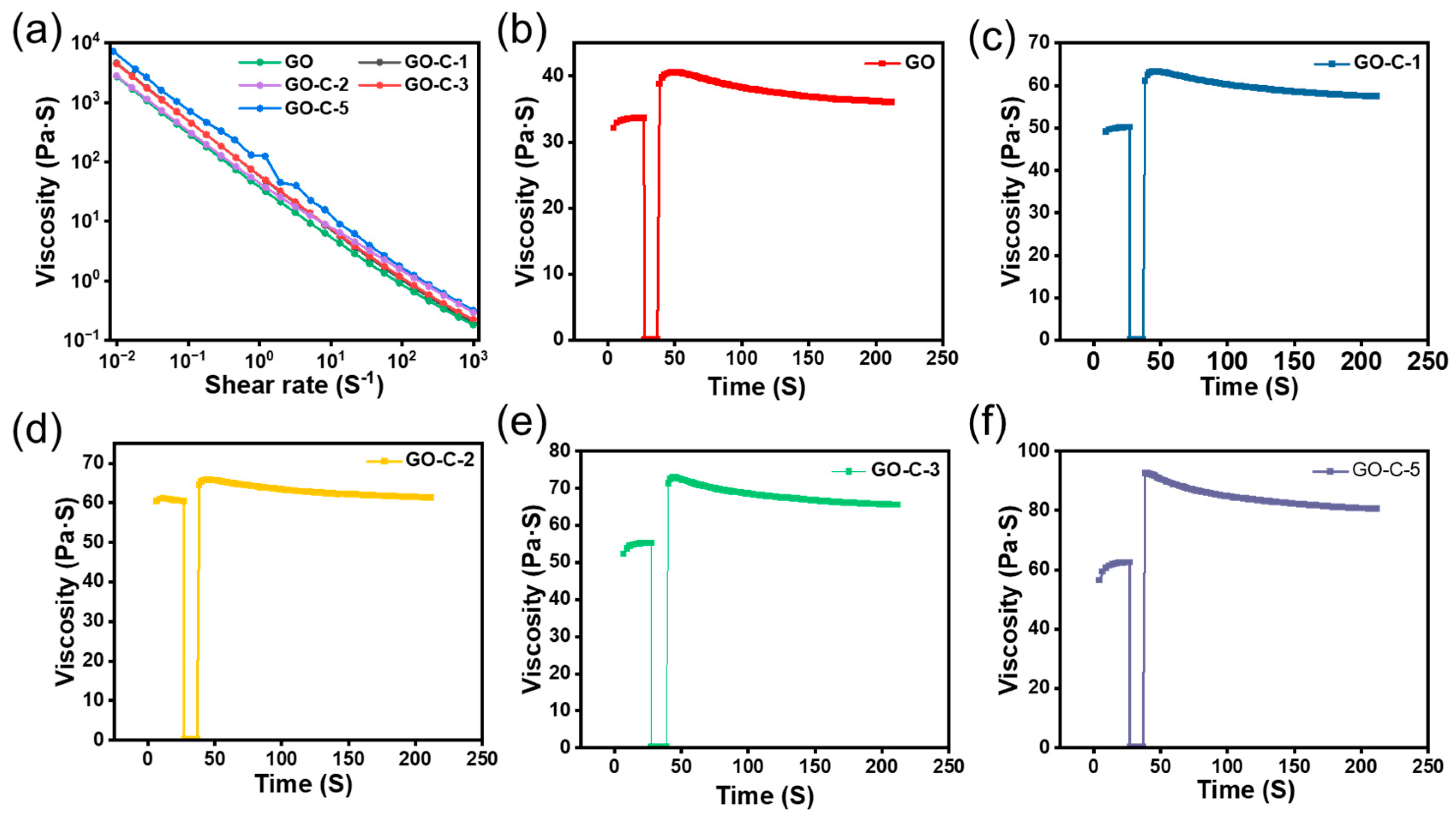
3.1. Morphology of GO

Figure 1 shows the viscosity change before and after the addition of CMC in GO.
As shown in Figure 1a,b, the viscosity of GO is higher than that of pure GO after the addition of CMC, which indicated that CMC could significantly increase the viscosity of the GO slurry.
The viscosity curve can reflect the flow characteristics of GO and GO-C at different shear rates. As shown in Figure 2a, GO and GO-C show pseudoplastic behavior in which the viscosity decreases with increasing shear rate. At the minimum shear speed, the viscosity of GO-C-5 is 7243 Pa·S, which is higher than GO (2684 Pa·S), GO-C-1 (2817 Pa·S), GO-C-2 (4440 Pa·S), and GO-C-3 (4600 Pa·S). The viscosity of GO-C slurries shows an increase with increasing CMC content. CMC can increase the viscosity of the GO slurry mainly due to the following reasons: the hydrophobic backbone of the polymer is bonded to the surrounding water molecules through hydrogen bonding, which increases the fluid volume of the polymer and decreases the space for the particles to move freely, increasing the viscosity of the system. This is the primary cause of the increase in the viscosity of GO caused by CMC. Additional observations of the viscosity change and recovery of the GO slurry can be made using 3ITT simulation. As shown in Figure 2b–f, for the GO slurry, the statistical time to recover 80% of the starting viscosity is 11 s. Compared to GO, the statistical time to restore 80% of the initial for GO-C-1, GO-C-2, GO-C-3, and GO-C-5 decreases to 10.7, 10.5, 10.1, and 9.7 S, respectively. These results indicate that GO-C-5 has the highest viscosity and the best ability to recover viscosity quickly.
The effect of CMC on the stability of the GO slurry is examined using the zeta potential, a physical characteristic displayed by any substance in a dispersion [32]. As shown in Figure 3a, the zeta potential of GO, GO-C-1, GO-C-2, GO-C-3, and GO-C-5 is −23.37 mV, −27.8 mV, −32.37 mV, −32.46 mV, and −40.21 mV, respectively, which indicates that the zeta potential shows an increase with the increase in CMC content.
The American Society for Testing and Materials (ASTM) standard for colloidal suspension stability states that a medium steady state is defined as a zeta potential between 20 and 30 mV, and a high steady state is defined as a zeta potential above 40 mV [33,34]. These results show that the zeta potential of the GO slurry is increasing with the increase in CMC content. This may be due to the hydrolysis of CMC to produce more negative charge. To further explore the effect of CMC on the aggregation state of GO sheets, the thickness and shape of GO sheets are investigated using AFM. The pre-processing step includes the following: Firstly, the graphene oxide slurry was diluted. The oxide layer on the surface of the mica sheet was removed with tape, after which the diluted graphene oxide suspension was dripped onto the mica sheet. Finally, the mica sheet was placed into an oven for drying. As shown in Figure 3b, the AFM image of GO-C shows a light brown color, which indicates that GO-C is well dispersed. Meanwhile, we can observe an obvious GO sheet from the AFM images. The physical diameter of the GO sheet is 1.6 μm, and the thickness of the GO sheet is 1.2 nm, indicating that the GO sheet in GO-C is close to single-layer [35]. These results prove that the GO sheets do not tend to agglomerate after CMC addition.

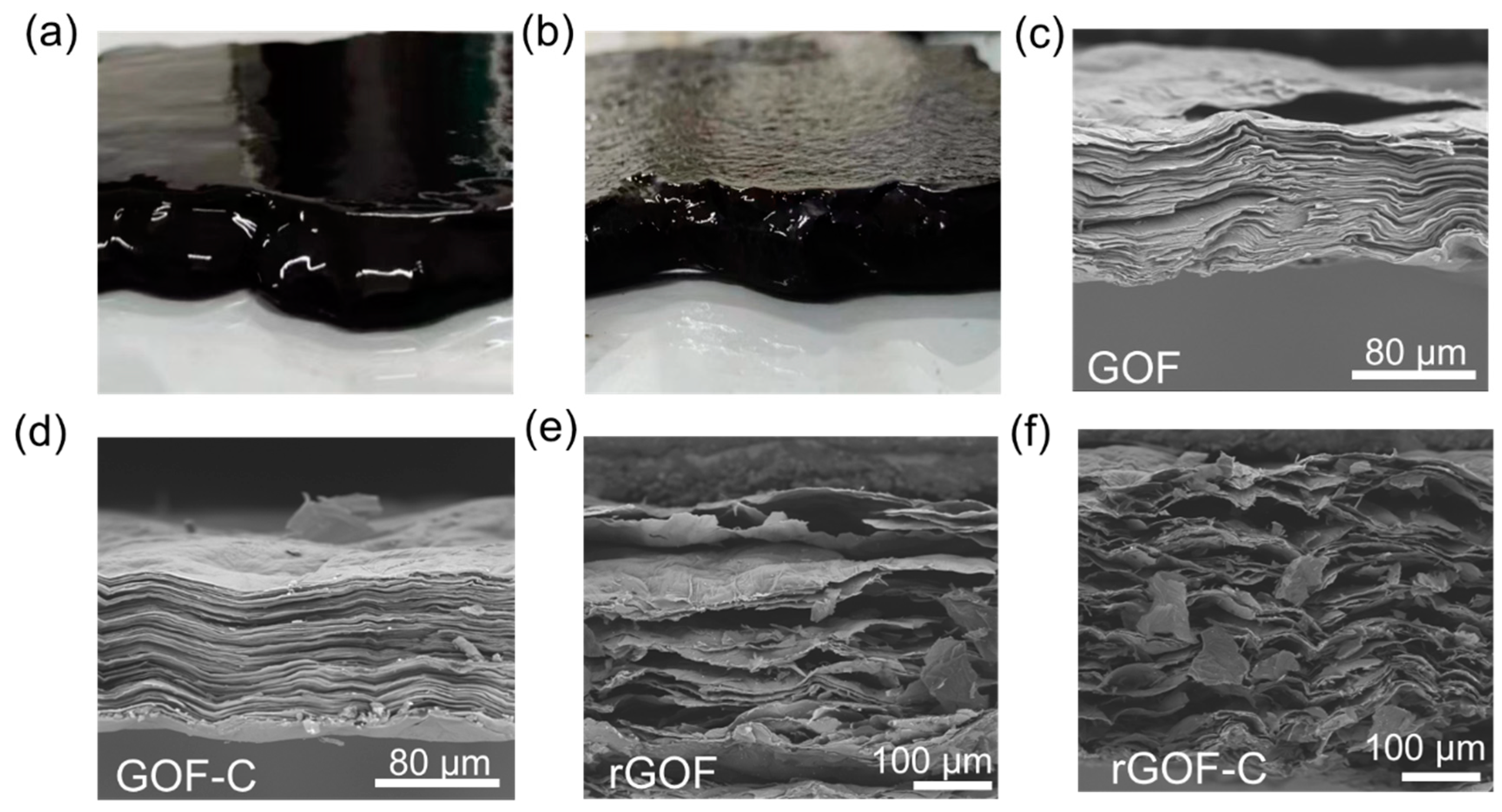
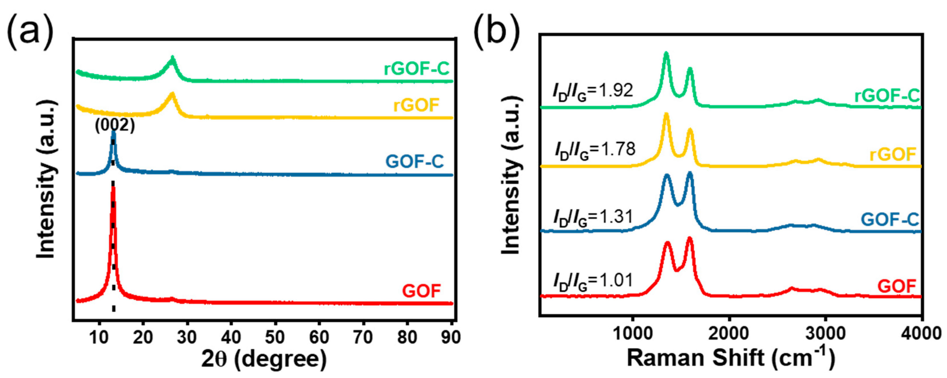
3.2. Morphology and Structure of GOF-C and rGOF-C

The GOF and GOF-C are fabricated by blade coating; as shown in Figure 4a, we can clearly observe that the edge of the GOF collapses due to the flow of the GO slurry in all directions. In contrast to this, there is no collapse around the GOF. These results are attributed to the fact that CMC greatly improves the viscosity of the GO slurry. After drying at 45 °C, the morphology of the GOF and GOF-C are investigated by the SEM. The cross-sectional SEM images of the GOF exhibit a layer-by-layer structure (Figure 4c). As shown in Figure 4d, the GOF-C exhibits a layer structure similar to that of the GOF, which indicates that the introduction of CMC does not disrupt the stacking structure of the graphene sheet.
We selected five points from the GOF and GOF-C to measure the thickness, which included the edge of the film and the middle of the film. The average thickness of the GOF-C is 895 μm, which is higher than the GOF (801 μm). As can be seen in Table 1, there is a roughly 100 times difference in the variation in GOF-C thickness (19,898.6) compared to the variance in GOF thickness (208.4). These results indicate that the thickness of the GOF-C from the edge to center is more uniform than the GOF due to the increase in the viscosity of the GO-C slurry. Previous findings state that a high number of pores are created and the film’s interlayer spacing increases as a result of the large volumes of gas released during the carbonization process [36,37,38]. After carbonization, the distinct pores can be observed in both the rGOF and rGOF-C in Figure 4e–f, with pore sizes ranging from a few micrometers to tens of micrometers. The rGO-C has significantly more pores than the rGO, which is because more gases are produced by the decomposition of CMC.
X-ray diffraction (XRD) patterns prove that the d-spacing of the products changed dramatically. As shown in Figure 5a, the characteristic diffraction peak of the GOF is located at 2θ = 13.04°, corresponding to the d-spacing of 0.68 nm. After the addition of CMC, the diffraction peaks at the same position with the GOF is observed, which indicates that CMC has no effect on the d-spacing of the GOF. After high-temperature heat treatment, the peaks of the rGOF and rGOF-C appear at 2θ = 26.52°. This structural change is mainly attributed to the oxygen-containing functional groups on graphene oxide at high temperatures [39,40].
The evolution of structural defects of films are investigated by Raman spectroscopy. As shown in Figure 5b, the two typical peaks of the GOF, GOF-C, rGOF, and rGOF-C appear near 1343 cm−1 (D-band) and 1585 cm−1 (G-band), respectively [41]. The ID/IG is used to represent structural defects of films, which is calculated by the peak area ratio of the D-band to the G-band. After the addition of CMC, the ID/IG of the GOF increases from 1.01 to 1.31, which indicates the increase in the disordered structure of the film. During high-temperature heat treatment, a large number of carbon atoms in the GO sheet are removed in the form of CO2 and CO, resulting in a large number of defects. Thus, the ID/IG values of the GOF and GOF-C increase from 1.01, 1.31 to 1.78, 1.92.
The rGOF and rGOF-C show excellent performance in EMI shielding. As shown in Figure 6a,b, the EMI SE of the rGO and rGO-C is investigated. The rGO has an EMI SET of 74–84 dB at 8–12 GHz; after the addition of CMC, the EMI SET of the rGOF-C is 91–96 GHz at 8–12 GHz. These results prove that the rGOF-C possesses a high and stable EMI shielding at 8–12 GHz. Meanwhile, the EMI SEA of the rGOF-C is 73–78 GHz at 8–12 GHz, which is higher than the 60–69 dB of the rGOF. Compared to the GOF, the EMI SET is higher and more uniform due to the uniform thickness.
We further explored the shielding mechanism of the rGOF and rGOF-C by analyzing the R, A, and T. The R of the rGOF and rGOF-C is more than 0.99, indicating that the rGO and rGO-C EMI SET is dominated by reflection. The A of the rGOF and rGOF-C range from 0.01 to 0.023 and 0.01 to 0.028, respectively, which indicates that the material absorbs less electromagnetic waves (Figure 6d). As can be shown in Figure 6e, the rGOF-C has very low T, which indicates that the rGOF-C has excellent shielding properties. These results indicate that using rGOF as a shielding material will result in more EM waves passing through the shielding material, which are directly radiated to the internal equipment that needs to be protected by the shielding layer. The EMI shielding mechanisms of the rGOF are shown in Figure 6f. After the electromagnetic wave comes into contact with the rGOF, the electromagnetic wave has three main destinations: reflected EM waves, transmitted EM waves, and absorbed waves. Compared to the rGOF, the rGOF-C has a higher and more stable EMI SE. These results could be attributed to the fact that the rGOF has more pores due to the gas released between the graphene layers. In these pores, EM waves can be scattered and reflected many times. Meanwhile, the high shielding performance also results from the high and uniform thickness of the rGOF, which could increase the number of phase interfaces, leading to EM waves being reflected and lost [42,43].

4. Conclusions

In this contribution, we introduced CMC into the GO slurry to increase the viscosity to prepare an rGOF with high and uniform thickness. After the addition of CMC, the GO slurries have higher viscosity and a better ability to recover viscosity quickly. Meanwhile, the addition of CMC facilitates the formation of a more stable colloidal solution for GO slurries. A GOF-C with high and uniform thickness is prepared by the GO-C slurry. After carbonization, more pores were generated on the GOF-C due to the gas released between the graphene layers. The high thickness and pore structure result in the shielding performance of the rGOF-C to be stabilized at 91–96 dB at 8–12 GHz, which is higher and more stable than pure reduced graphene oxide films. This work provides an effective strategy for the preparation of reduced graphene films with high and uniform thickness for EMI SE.

Author Contributions

M.L.: investigation, formal analysis, data curation, writing—original draft, and writing—review and editing. L.-J.X.: resources, formal analysis, project administration, writing—original draft, and writing—review and editing. Z.-L.Y.: formal analysis, software, resources, writing—review and editing, and project administration. D.L.: formal analysis, writing—review and editing, and data curation. Z.W.: validation, methodology, and formal analysis. R.-H.N.: investigation and formal analysis. H.J.: resources, project administration, supervision, and funding acquisition. Q.-Q.K.: resources, writing—original draft, and formal analysis. All authors have read and agreed to the published version of the manuscript.

Funding

This research was funded by the National Natural Science Foundation of China (52202055), Scientific and Technological Key Project of Shanxi Province (202101040201005), National Natural Science Foundation of China (22379157), Fundamental Research Program of Shanxi Province (20210302124101), Key Research and Development (R&D) Projects of Shanxi Province (2022ZDYF027), and Research Project Supported by ICC CAS, SCJC-XCL-2023-12. All authors have read and agreed to the published version of the manuscript.

Data Availability Statement

Data underlying the results presented in this paper are not publicly. Available at this time but may be obtained from the authors on reasonable request.

Conflicts of Interest

The authors declare no conflict of interest.

References

  1. Iqbal, A.; Shahzad, F.; Hantanasirisakul, K.; Kim, M.-K.; Kwon, J.; Hong, J.; Kim, H.; Kim, D.; Gogotsi, Y.; Koo, C.M. Anomalous absorption of electromagnetic waves by 2D transition metal carbonitride Ti3CNTx (MXene). Science 2020, 369, 446–450. [Google Scholar] [CrossRef]
  2. Xin, W.; Xi, G.Q.; Cao, W.T.; Ma, C.; Liu, T.; Ma, M.G.; Bian, J. Lightweight and flexible MXene/CNF/silver composite membranes with a brick-like structure and high-performance electromagnetic-interference shielding. RSC Adv. 2019, 9, 29636–29644. [Google Scholar] [CrossRef]
  3. Wan, Y.-J.; Zhu, P.-L.; Yu, S.-H.; Sun, R.; Wong, C.-P.; Liao, W.-H. Ultralight, super-elastic and volume-preserving cellulose fiber/graphene aerogel for high-performance electromagnetic interference shielding. Carbon 2017, 115, 629–639. [Google Scholar] [CrossRef]
  4. Zhou, E.; Xi, J.; Liu, Y.; Xu, Z.; Guo, Y.; Peng, L.; Gao, W.; Ying, J.; Chen, Z.; Gao, C. Large-area potassium-doped highly conductive graphene films for electromagnetic interference shielding. Nanoscale 2017, 9, 18613–18618. [Google Scholar] [CrossRef]
  5. Abbasi, H.; Antunes, M.; Velasco, J.I. Recent advances in carbon-based polymer nanocomposites for electromagnetic interference shielding. Prog. Mater. Sci. 2019, 103, 319–373. [Google Scholar] [CrossRef]
  6. Wang, K.; Zuo, Z.; Sang, L.; Zhu, X. Comprehensive Analysis for Electromagnetic Shielding Method Based on Mesh Aluminium Plate for Electric Vehicle Wireless Charging Systems. Energies 2022, 15, 1546. [Google Scholar] [CrossRef]
  7. Renteria, J.D.; Ramirez, S.; Malekpour, H.; Alonso, B.; Centeno, A.; Zurutuza, A.; Cocemasov, A.I.; Nika, D.L.; Balandin, A.A. Strongly Anisotropic Thermal Conductivity of Free-Standing Reduced Graphene Oxide Films Annealed at High Temperature. Adv. Funct. Mater. 2015, 25, 4664–4672. [Google Scholar] [CrossRef]
  8. Shen, B.; Zhai, W.; Zheng, W. Ultrathin Flexible Graphene Film: An Excellent Thermal Conducting Material with Efficient EMI Shielding. Adv. Funct. Mater. 2014, 24, 4542–4548. [Google Scholar] [CrossRef]
  9. Cao, M.-S.; Song, W.-L.; Hou, Z.-L.; Wen, B.; Yuan, J. The effects of temperature and frequency on the dielectric properties, electromagnetic interference shielding and microwave-absorption of short carbon fiber/silica composites. Carbon 2010, 48, 788–796. [Google Scholar] [CrossRef]
  10. Jia, H.; Yang, X.; Kong, Q.-Q.; Xie, L.-J.; Guo, Q.-G.; Song, G.; Liang, L.-L.; Chen, J.-P.; Li, Y.; Chen, C.-M. Free-standing, anti-corrosion, super flexible graphene oxide/silver nanowire thin films for ultra-wideband electromagnetic interference shielding. J. Mater. Chem. A 2021, 9, 1180–1191. [Google Scholar] [CrossRef]
  11. Wen, B.; Cao, M.; Lu, M.; Cao, W.; Shi, H.; Liu, J.; Wang, X.; Jin, H.; Fang, X.; Wang, W.; et al. Reduced Graphene Oxides: Light-Weight and High-Efficiency Electromagnetic Interference Shielding at Elevated Temperatures. Adv. Mater. 2014, 26, 3484–3489. [Google Scholar] [CrossRef] [PubMed]
  12. Liu, H.; Wu, S.; You, C.; Tian, N.; Li, Y.; Chopra, N. Recent progress in morphological engineering of carbon materials for electromagnetic interference shielding. Carbon 2021, 172, 569–596. [Google Scholar] [CrossRef]
  13. Gupta, S.; Chang, C.; Anbalagan, A.K.; Lee, C.-H.; Tai, N.-H. Reduced graphene oxide/zinc oxide coated wearable electrically conductive cotton textile for high microwave absorption. Compos. Sci. Technol. 2020, 188, 107994. [Google Scholar] [CrossRef]
  14. Song, C.; Yin, X.; Han, M.; Li, X.; Hou, Z.; Zhang, L.; Cheng, L. Three-dimensional reduced graphene oxide foam modified with ZnO nanowires for enhanced microwave absorption properties. Carbon 2017, 116, 50–58. [Google Scholar] [CrossRef]
  15. Putz, K.W.; Compton, O.C.; Segar, C.; An, Z.; Nguyen, S.T.; Brinson, L.C. Evolution of Order During VacuumAssisted Self-Assembly of Graphene Oxide Paper and Associated Polymer Nanocomposites. ACS Nano 2011, 5, 6601–6609. [Google Scholar] [CrossRef] [PubMed]
  16. Hu, D.; Gong, W.; Di, J.; Li, D.; Li, R.; Lu, W.; Gu, B.; Sun, B.; Li, Q. Strong graphene-interlayered carbon nanotube films with high thermal conductivity. Carbon 2017, 118, 659–665. [Google Scholar] [CrossRef]
  17. Zhou, E.; Xi, J.; Guo, Y.; Liu, Y.; Xu, Z.; Peng, L.; Gao, W.; Ying, J.; Chen, Z.; Gao, C. Synergistic effect of graphene and carbon nanotube for high-performance electromagnetic interference shielding films. Carbon 2018, 133, 316–322. [Google Scholar] [CrossRef]
  18. Liu, Z.; Li, Z.; Xu, Z.; Xia, Z.; Hu, X.; Kou, L.; Peng, L.; Wei, Y.; Gao, C. Wet-Spun Continuous Graphene Films. Chem. Mater. 2014, 26, 6786–6795. [Google Scholar] [CrossRef]
  19. Zhang, M.; Huang, L.; Chen, J.; Li, C.; Shi, G. Ultratough, ultrastrong, and highly conductive graphene films with arbitrary sizes. Adv. Mater. 2014, 26, 7588–7592. [Google Scholar] [CrossRef]
  20. Xin, G.; Sun, H.; Hu, T.; Fard, H.R.; Sun, X.; Koratkar, N.; Borca-Tasciuc, T.; Lian, J. Large-area freestanding graphene paper for superior thermal management. Adv. Mater. 2014, 26, 4521–4526. [Google Scholar] [CrossRef]
  21. Guo, Y.; Dun, C.; Xu, J.; Mu, J.; Li, P.; Gu, L.; Hou, C.; Hewitt, C.A.; Zhang, Q.; Li, Y.; et al. Ultrathin, Washable, and Large-Area Graphene Papers for Personal Thermal Management. Small 2017, 13, 1702645. [Google Scholar] [CrossRef] [PubMed]
  22. Yang, S.; Tao, Z.; Li, X.; Liu, J.; Kong, Q.; Tong, Y.; Li, J.; Liu, Z. Reduced graphene oxide layers full of bubbles for electromagnetic interference shielding. J. Mater. Chem. C 2023, 11, 1949–1959. [Google Scholar] [CrossRef]
  23. Xu, Y.; Yang, Y.; Yan, D.-X.; Duan, H.; Zhao, G.; Liu, Y. Flexible and conductive polyurethane composites for electromagnetic shielding and printable circuit. Chem. Eng. J. 2019, 360, 1427–1436. [Google Scholar] [CrossRef]
  24. Zhang, Y.; Zhang, G.; Shi, X.; Gao, Q.; Huang, F.; Xiao, R. A flexible and strong reduced graphene oxide film for high-performance electromagnetic shielding. Compos. Commun. 2021, 28, 100954. [Google Scholar] [CrossRef]
  25. Xu, L.; Wang, L.; Zhang, W.; Xue, J.; Hou, S. The Reinforced Electromagnetic Interference Shielding Performance of Thermal Reduced Graphene Oxide Films via Polyimide Pyrolysis. ACS Omega 2022, 7, 10955–10962. [Google Scholar] [CrossRef] [PubMed]
  26. Chen, J.; Yao, B.; Li, C.; Shi, G. An improved Hummers method for eco-friendly synthesis of graphene oxide. Carbon 2013, 64, 225–229. [Google Scholar] [CrossRef]
  27. Marcano, D.C.; Kosynkin, D.V.; Berlin, J.M.; Sinitskii, A.; Sun, Z.; Slesarev, A.; Alemany, L.B.; Lu, W.; Tour, J.M. Improved Synthesis of Graphene Oxide. ACS Nano 2010, 4, 4806–4814. [Google Scholar] [CrossRef] [PubMed]
  28. Cheng, Z.; Guo, L.; Dong, Q.; Wang, C.; Yao, Q.; Gu, X.; Yang, J.; Qian, Y. Highly Durable and Ultrafast Cycling of Dual-Ion Batteries via In Situ Construction of Cathode–Electrolyte Interphase. Adv. Energy Mater. 2022, 12, 2202253. [Google Scholar] [CrossRef]
  29. Song, G.; Yi, Z.; Su, F.; Xie, L.; Wang, Z.; Wei, X.-X.; Xu, G.; Chen, C.-M. Boosting the Low-Temperature Performance for Li-Ion Batteries in LiPF6-Based Local High-Concentration Electrolyte. ACS Energy Lett. 2023, 8, 1336–1343. [Google Scholar] [CrossRef]
  30. Yang, X.; Li, X.-M.; Kong, Q.-Q.; Liu, Z.; Chen, J.-P.; Jia, H.; Liu, Y.-Z.; Xie, L.-J.; Chen, C.-M. One-pot ball-milling preparation of graphene/carbon black aqueous inks for highly conductive and flexible printed electronics. Sci. China Mater. 2019, 63, 392–402. [Google Scholar] [CrossRef]
  31. Shen, B.; Li, Y.; Zhai, W.; Zheng, W. Compressible Graphene-Coated Polymer Foams with Ultralow Density for Adjustable Electromagnetic Interference (EMI) Shielding. ACS Appl. Mater. Interfaces 2016, 8, 8050–8057. [Google Scholar] [CrossRef]
  32. Kim, T.Y.; Lee, H.W.; Stoller, M.; Dreyer, D.R.; Bielawski, C.W.; Ruoff, R.S.; Suh, K.S. High-Performance Supercapacitors Based on Poly(ionic liquid)-Modified Graphene Electrodes. ACS Nano 2011, 5, 436–442. [Google Scholar] [CrossRef] [PubMed]
  33. Valverde, J. Methods used to determine the zeta potential of colloids in wastewater. J. Sci. Eng. 2017, 1, 19–32. [Google Scholar] [CrossRef]
  34. Krishnamoorthy, K.; Veerapandian, M.; Yun, K.; Kim, S.J. The chemical and structural analysis of graphene oxide with different degrees of oxidation. Carbon 2013, 53, 38–49. [Google Scholar] [CrossRef]
  35. Rozada, R.; Paredes, J.I.; Lopez, M.J.; Villar-Rodil, S.; Cabria, I.; Alonso, J.A.; Martinez-Alonso, A.; Tascon, J.M. From graphene oxide to pristine graphene: Revealing the inner workings of the full structural restoration. Nanoscale 2015, 7, 2374–2390. [Google Scholar] [CrossRef]
  36. Chen, C.-M.; Zhang, Q.; Yang, M.-G.; Huang, C.-H.; Yang, Y.-G.; Wang, M.-Z. Structural evolution during annealing of thermally reduced graphene nanosheets for application in supercapacitors. Carbon 2012, 50, 3572–3584. [Google Scholar] [CrossRef]
  37. Larciprete, R.; Fabris, S.; Sun, T.; Lacovig, P.; Baraldi, A.; Lizzit, S. Dual path mechanism in the thermal reduction of graphene oxide. J. Am. Chem. Soc. 2011, 133, 17315–17321. [Google Scholar] [CrossRef]
  38. Qiu, Y.; Guo, F.; Hurt, R.; Kulaots, I. Explosive thermal reduction of graphene oxide-based materials: Mechanism and safety implications. Carbon N. Y. 2014, 72, 215–223. [Google Scholar] [CrossRef]
  39. Chen, X.; Deng, X.; Kim, N.Y.; Wang, Y.; Huang, Y.; Peng, L.; Huang, M.; Zhang, X.; Chen, X.; Luo, D.; et al. Graphitization of graphene oxide films under pressure. Carbon 2018, 132, 294–303. [Google Scholar] [CrossRef]
  40. Chen, C.-M.; Huang, J.-Q.; Zhang, Q.; Gong, W.-Z.; Yang, Q.-H.; Wang, M.-Z.; Yang, Y.-G. Annealing a graphene oxide film to produce a free standing high conductive graphene film. Carbon 2012, 50, 659–667. [Google Scholar] [CrossRef]
  41. Yang, D.; Velamakanni, A.; Bozoklu, G.; Park, S.; Stoller, M.; Piner, R.D.; Stankovich, S.; Jung, I.; Field, D.A.; Ventrice, C.A.; et al. Chemical analysis of graphene oxide films after heat and chemical treatments by X-ray photoelectron and Micro-Raman spectroscopy. Carbon 2009, 47, 145–152. [Google Scholar] [CrossRef]
  42. Jia, Z.; Zhang, M.; Liu, B.; Wang, F.; Wei, G.; Su, Z. Graphene Foams for Electromagnetic Interference Shielding: A Review. ACS Appl. Nano Mater. 2020, 3, 6140–6155. [Google Scholar] [CrossRef]
  43. Zhang, H.; Liu, T.; Huang, Z.; Cheng, J.; Wang, H.; Zhang, D.; Ba, X.; Zheng, G.; Yan, M.; Cao, M. Engineering flexible and green electromagnetic interference shielding materials with high performance through modulating WS2 nanosheets on carbon fibers. J. Mater. 2022, 8, 327–334. [Google Scholar] [CrossRef]
Figure 1. The macroscopic photograph of (a) GO and (b) GO-C-5.
Crystals 14 00322 g001
Figure 2. (a) Viscosity for GO, GO-C-1, GO-C-2, GO-C-3, and GO-C-5 slurries displayed as a function of shear rate. (bf) Viscosity versus time for GO, GO-C-1, GO-C-2, GO-C-3, and GO-C-5 in 3ITTs.
Crystals 14 00322 g002
Figure 3. (a) The zeta potential of GO, GO-C-1, GO-C-2, GO-C-3, and GO-C-5. (b) The AFM image of GOF−5. The line profile of the GO nanosheets is shown in (c).
Crystals 14 00322 g003
Figure 4. The macroscopic photograph of the (a) GOF and (b) GOF-C. The cross-sectional SEM image of the (c) GOF, (d) GOF-C, (e) rGOF, and (f) rGOF-C.
Crystals 14 00322 g004
Figure 5. (a) XRD spectra of GOF, GOF-C, rGOF, and rGOF-C. (b) Raman spectra of GOF, GOF-C, rGOF, and rGOF-C.
Crystals 14 00322 g005
Figure 6. (a) EMI SE of rGOF in X-band. (b) EMI SE of rGOF-C in X-band. (c) Reflected coefficient, (d) absorption coefficient (A), and (e) transmission coefficient (T) of rGOF and rGO-C. (f) EMI shielding mechanism for rGOF-C.
Crystals 14 00322 g006
Table 1. Thickness of GOF and GOF-C are measured by micrometer.
Sample12345 X ¯ S 2
GO
(μm)
54575388989692380119,898.6
GOF-C
(μm)
889873915894906895208.4
Disclaimer/Publisher’s Note: The statements, opinions and data contained in all publications are solely those of the individual author(s) and contributor(s) and not of MDPI and/or the editor(s). MDPI and/or the editor(s) disclaim responsibility for any injury to people or property resulting from any ideas, methods, instructions or products referred to in the content.

