Abstract
This paper introduces a new kind of quasicrystal by Fibonacci-spacing a multigrid of a certain symmetry, like , , , etc. Multigrids of a certain symmetry can be used to generate quasicrystals, but multigrid vertices are not a quasicrystal due to arbitrary closeness. By Fibonacci-spacing the grids, the structure transit into an aperiodic order becomes a quasicrystal itself. Unlike the quasicrystal generated by the dual-grid method, this kind of quasicrystal does not live in the dual space of the grid space. It is the grid space itself and possesses quasicrystal properties, except that its total number of vertex types are not finite and fixed for the infinite size of the quasicrystal but bounded by a slowly logarithmic growing number. A 2D example, the Fibonacci pentagrid, is given. A 3D example, the Fibonacci icosagrid (FIG), is also introduced, as well as its subsets, the Fibonacci tetragrid (FTG). The FIG can be thought of as a golden composition of five sets of FTGs. The golden composition procedure is another way to transit a random structure into aperiodic order, and the associated rotational angle is the same as the angle that resolves the geometric frustration for the tetrahedral clusters. The FIG resembles another quasicrystal that is the same golden composition of five quasicrystals that are cut and projected and sliced from the lattice. This leads to further exploration in mapping the FIG to the lattice, and the results will be published following this paper.
1. Introduction
The discovery of quasicrystals [1], the second kind of impossible [2], drew interest from scientists from various disciplines, such as math, physics, materials science, chemistry, and biology [3,4,5,6,7]. Soon after, there was a surge of interest in studying the mathematical aspects of quasicrystals [8,9,10,11,12,13]. Recently, however, the majority of research in the field has shifted toward the physical aspects of quasicrystals [14,15,16,17] and their growth [18,19,20]. This leaves the mathematical properties of quasicrystals still relatively unexplored. Investigation in this field provides opportunity for discoveries that could have far-reaching consequences in physics and other disciplines.
While there is still no commonly agreed upon definition of a quasicrystal [5,8,21], it is generally believed that for a structure to be a quasicrystal, it should have the following properties:
- It is ordered but not periodic.
- It has long-range quasiperiodic translational order and long-range orientational order. In other words, for any finite patch within the quasicrystal, you can find an infinite number of identical patches at other locations with translational and rotational transformations.
- It has finite types of prototiles/unit cells.
- It has a discrete diffraction pattern.
The lack of consensus on the definition obfuscates the classification of construction methods.
Recent advancements in the field, including Else’s exploration of the quantum many-body topology in quasicrystals [22], have opened new theoretical frontiers. The works of Baggioli et al. [23,24] on viscoelastic models and phason dynamics have significantly advanced our understanding of quasicrystal physics. Furthermore, Amaral’s research in the theory of topological quasicrystals, particularly through geometric state sum models [25] and the exploration of anyonic behavior in quasicrystals for quantum computing [26], has been pivotal. These studies underscore the complex interplay between topology and the unique properties of quasicrystals, closely aligning with the theoretical underpinnings of our Fibonacci icosagrid (FIG) model.
Quasicrystals can be mathematically generated via three common methods: the deflation rule method [5,27], the cut-and-project method [5,27,28], and the dual-grid method [5,27,28]. This paper studies a third, less common method, the Fibonacci multigrid method, which is first introduced as a special case of the generalized dual-grid method discussed by Socolar et al. [27]. This new method focuses on generating a new class of quasicrystals in the grid space rather than the cell space. As an illustration, we present the Fibonacci pentagrid (FPG) as a 2D example and the Fibonacci icosagrid (FIG) as a 3D example. Notably, the FIG bears a striking resemblance to a 3D quasicrystal that composites five 3D slices of the Elser–Sloane quasicrystal found from the lattice via the cut-and-project method [29].
This paper includes three sections. In Section 2, we introduce the Fibonacci multigrid method for generating a new class of quasicrystals, exploring the FPG as a 2D example. Section 3 introduces the FIG as an -symmetric quasicrystal and describes how it can be found as a golden composite (defined in later sections) of five Fibonacci tetragrids (FTGs). We highlight a similarity between the FIG and another 3D quasicrystal, a compound quasicrystal (CQC) that is a golden composite of five cut-and-project slices from the lattice, which suggests a mapping between the FIG and the lattice. The last section, Section 4, summarizes the paper.
2. Fibonacci Mutigrid—A New Kind of Quasicrystal
To compare and contrast the dual-grid method with the Fibonacci multigrid method, we highlight two pentagonal grids, the pentagrid and the FPG, shown in Figure 1. Each method uses these grids to create 2D quasicrystals.
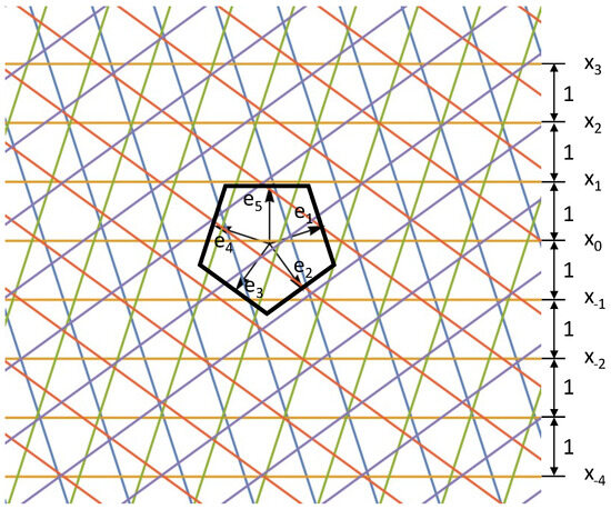
Figure 1.
An example of a pentagrid, where , , …, are the normal vectors of the grids and each parallel grid set is denoted a different color.
2.1. Review of the Dual-Grid Method
The pentagrid is a periodic grid commonly used as a dual grid for generating Penrose tilings. A pentagon has five normal vectors, which can be chosen as
A pentagrid is defined as
with
where are the normal vectors of the parallel grid lines for and T is a constant “wavelength” specifying the distance between the parallel grid lines. The real number is the phase or offset of with respect to the origin. Figure 1 shows an example of a pentagrid.
Figure 2 shows the process of constructing a Penrose tiling with this pentagrid:
- The last step is to place the rhombi edge to edge while maintaining their original topological connectedness. For example, as shown in Figure 2B, although the cells are translated to be placed edge to edge, cell 1 is always connected to cell 2 through the vertical edge, cell 2 is connected to cell 3 through the other non-vertical edge, and so on.
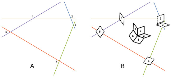
Figure 2.
To construct a Penrose tiling from the dual-grid method, first (A) identify the intersections in a sample patch in the pentagrid, (B) construct a dual quasicrystal cell (here, the prolate and oblate rhombi) at each intersect point, and then place them edge to edge while maintaining their topological connectedness.
If the values of the offset are properly chosen so that there are no more than two lines intersecting at one point (to avoid glue tiles [27]), then the resulting quasicrystal will be a Penrose tiling. As we can see from this procedure, each vertex (intersection) in the pentagrid will eventually correspond to a cell in the Penrose tiling, and each vertex in the Penrose tiling will correspond to a cell in the pentagrid. Therefore, the grid space and the cell space are dual to each other.
2.2. Fibonacci Multigrid Method
Although its dual is a quasicrystal, the pentagrid itself is not a quasicrystal due to the arbitrary closeness between the vertices (Figure 3A) which results in an infinite number of unit cells. We discovered that a modification can be applied to the periodic grid to make the grid itself quasiperiodic. This structure was previously introduced by Socolar et al. in 1986 for the dual-grid method. The modification is to change Equation (3) from periodic to quasiperiodic [27]:
where , , and , are irrational, and is the floor function and denotes the greatest integer less than or equal to the argument. As N can be all integers, including negative integers, we can set all the other variables in this expression to be positive without losing its generality. This expression defines a quasiperiodic sequence of two different spacings, L and S, with a ratio of . Changing , , and can change the relative frequency of the two spacings, the offsets of the grid, and the order of the sequence of the two spacings, respectively.
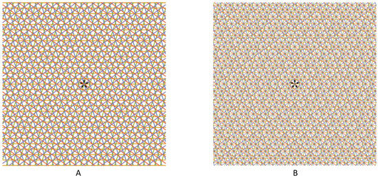
Figure 3.
(A) Pentagrid and (B) Fibonacci pentagrid, with the quasicrystallized pentagrid using Fibonacci-sequence spacing.
This paper focuses on a special case of the quasiperiodic grid, where and is the golden ratio. In this case, defines a Fibonacci chain, a 1D quasicrystal [8]. To obtain a quasicrystal with rotational symmetry at the origin, consider and , giving a palindromic Fibonacci chain with 180-degree rotational symmetry. When the palindromic Fibonacci chain is used for creating a multigrid in higher dimensions, the vertices found in this Fibonacci multigrid will also have rotational symmetry at the origin.
The modified pentagrid is called the Fibonacci pentagrid (FPG) [27]. We study the case with a center of this structure where all five grids intersect at the same point and the spacing of each set of the grid from this point is a palindromic Fibonacci chain, where and , as shown in Figure 4. Not only the dual of the FPG is a quasicrystal (a Penrose tiling), but the FPG itself is also a quasicrystal, a new kind of quasicrystal that is different from the conventional ones, since it is in the grid space itself instead of the dual tiling space. Moreover, the FPG has some special properties. As we mentioned earlier, having a fixed, finite number of vertex types is an important property of quasicrystals. Figure 3B clearly shows that, compared with the periodic spacing, the Fibonacci spacing significantly reduced the number of vertex types and that the arbitrary closeness has disappeared. However, we found that in the FPG, the number of vertex types are a relatively small finite number for a patch of any size, yet the number will grow, although slowly, as the size of the quasicrystal patch grows. In other words, the Fibonacci spacing does bring the randomness of the periodic grids to order, but this order is more like a second-degree order because it appears that the first-degree order indeed is there, but there is another layer of order, like slow, further subdividing in the existing vertex types, like how fractals work.
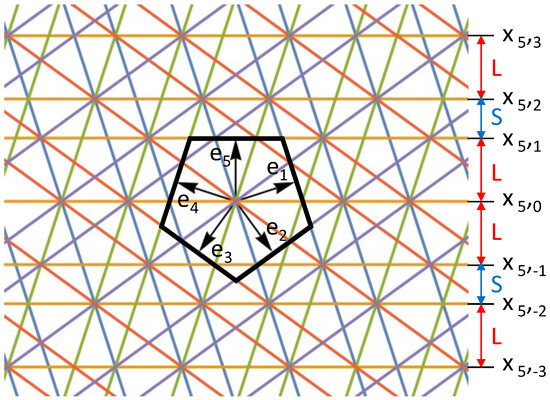
Figure 4.
Fibonacci pentagrid construction.
We investigated the total number of vertex types in the FPG by looking at the number of different segment intervals along each grid. The coordinate of the intersection points on one grid line can be expressed as follows: , where a and b are integers, but the ratio of a and b should be close to the , where n can be any integer (for a finite patch, n is also a small set of integers). For now, we are not sure about this restriction on the choices of a and b, so to calculate an upper bound of the number of different segment intervals, we allow a and b to be any arbitrary integer. Figure 5 shows how the number of intervals change as the range of a and b increases. Clearly, the number of intervals increases with the increasing of the range of a and b, but the change rate becomes slower and slower. While it appears to be logarithmic and does not have an upper bound, one might wonder if there will be more "disorder" with more vertex types as the size of the quasicrystal increases, but this is actually not the case. We noticed that the way the extra interval types are introduced is not at all random, and it is more like a fractal. The available intervals are slowly becoming subdivided at the golden division point into new ones. This is itself another kind of order, an order of fractal subdivision.
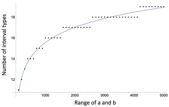
Figure 5.
The number of interval increases logarithmicly as the range of a and b increases, for a line with point coordinates , where a and b are integers.
The Fibonacci multigrid method can be summarized in the following steps (refer to Figure 4 for the FPG case):
- Consider a d-dimensional polytope centered around the origin, such as a convex regular polytope. Identify the normal vectors for each facet (-dimensional face or hyperface).
- Extend a hyperplane from each facet to infinity. The normal vectors of each facet are given by a normal vector .
- Along each normal vector, place an infinite number of parallel hyperplanes that are aperiodically spaced by the Fibonacci chain. Choose the Fibonacci chain that contains a 180-degree rotational symmetry at the origin. The first letter in the Fibonacci chain is an edge extending from the origin to the facet.
- Find the quasicrystal by identifying all interaction vertices between the Fibonacci-spaced hyperplanes.
This paper calls this new method for generating quascirystals in the grid space the Fibonacci multigrid method and the quasicrystal. The quasicrystal generated from the facet normal vectors of a given polytope is named after the polytope. For example, the Fibonacci pentagrid is named after the pentagon, while the Fibonacci icosagrid (FIG) and the Fibonacci tetragrid (FTG) are 3D quasicrystals that are named after the icosahedron and tetrahedron, respectively. The FIG and FTG will be discussed in the Section 3.
3. Fibonacci Icosagrid and Fibonacci Tetragrid
3.1. Icosagrid and Its 1/5th, Tetragrid
The 3D examples of the Fibonacci multigrid include the Fibonacci dodecagrid, Fibonacci icosagrid, Fibonacci cubigrid, and the Fibonacci tetragrid, with the normal vectors of the planar grids as the normal vectors of the facets of the dodecahedron, icosahedron, cube, and tetrahedron, respectively. This paper focuses on the Fibonacci tetragrid and the Fibonnaci icosagrid. First, we briefly discuss the properties of the two periodic multigrids, the tetragrid and the icosagrid, before introducing the FTG and FIG.
An icosagrid is defined as a three-dimensional, planar, periodic 10-grid. The normal vectors of its ten planar grids, denoted as for , align with the ten three-fold symmetry axes of an icosahedron, as illustrated in Figure 6. By specifying these normal vectors, an icosagrid can be generated using Equations (2) and (3) when setting . This structure segments three-dimensional space into an infinite array of three-dimensional cells. Our focus, however, is on the properties of the icosagrid when exclusively considering unit-length regular tetrahedral cells (with a height denoted as “L”), as depicted in Figure 7A.
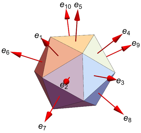
Figure 6.
The normal vectors of the icosagrid: , , …, .
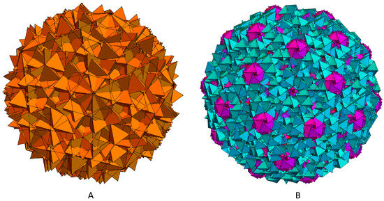
Figure 7.
(A) Icosagrid with regular tetrahedral cells shown and (B) tetrahedra from the Fibonacci icosagrid with 20Gs colored in magenta.
In parallel to an icosagrid, a tetragrid is a three-dimensional, planar, periodic 4-grid. Its four planar grids’ normal vectors, for , correspond with the four three-fold symmetry axes of a tetrahedron. At , the tetragrid transforms into a periodic face-centered cubic (FCC) lattice. This structure can be envisioned as a space-filling amalgamation of regular tetrahedral cells in two orientations and octahedral cells, as shown in Figure 8A. These tetrahedra, despite differing orientations, share the same vertex set.
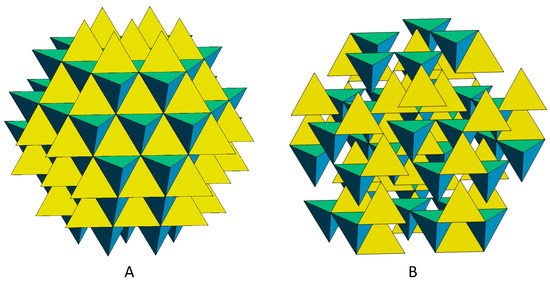
Figure 8.
(A) Tetragrid with tetrahedral cells of two different orientations (yellow and cyan) and (B) tetrahedra from the Fibonacci tetragrid.
We found an interesting connection between the icosagrid and the tetragrid: the 10 icosahedron normal vectors can form five sets of 4 vectors (with duplications), with each set matching the 4 normal vectors of a tetrahedron. The icosagrid, thus, can be conceptualized as a composite of five tetragrid sets, amalgamated through a golden composition procedure, detailed in Figure 9.
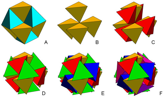
Figure 9.
(A) A small tetragrid local cluster with eight tetrahedral cells, four “up” and four “down”. (B–F) The golden composition process, each color denotes a differetn tetrahedron-4-cluster.
- Our procedure starts at the origin of the tetragrid, where we identify eight tetrahedral cells converging at this point. These are divided into two sets based on orientation: four cells in one orientation and the remaining four in the dual orientation, as illustrated by the yellow tetrahedra in Figure 9A.
- We select the four tetrahedral cells of identical orientation, as shown in Figure 9B, and replicate them to create four copies.
- Two of these copies are then positioned together, ensuring they share their central point. Three of their tetrahedral faces are aligned to be parallel and in contact. This arrangement incorporates a relative rotation angle of —referred to as the golden rotation, as demonstrated in Figure 9C between the gold and red tetrahedron-4-clusters (see [30]).
- This process is repeated three additional times to integrate the remaining three copies—colored green, blue, and pink—into the existing gold and red structure, as depicted in Figure 9C–E. The culmination of this procedure results in a composite structure of five tetrahedron-4-clusters, forming a twisted 20-tetrahedron cluster, or the 20-group (20G), as shown in Figure 9F.
- Subsequently, each tetrahedron-4-cluster is expanded into its full tetragrid form, with only the tetrahedra of the same orientation being considered active. This configuration yields a structure analogous to a chiral icosagrid, depicted in Figure 7A. Conversely, activating the tetrahedral cells of the alternate orientation results in an icosagrid of opposite chirality.
Originally, the inspiration for this golden composition procedure was derived from our analysis of twisted clusters associated with the golden rotational angle [30]. This concept found further resonance in Niu et al.’s exploration of linear and nonlinear spin–orbital coupling in golden-angle spiral quasicrystals [31]. We also discovered that this angle plays a critical role in encoding a 4D discrete curvature (dihedral angle) into a 3D twist, a notion we delve into in our ‘Geometric Frustration’ paper. These intricate relationships will be elaborated in the subsequent paper of this series.
The tetragrid forms a crystal of tetrahedra and octahedra. The icosagrid, like the pentagrid, is not a quasicrystal because of the arbitrary closeness and therefore infinite number of cell shapes it possesses. Also, it does not satisfy the second property of a quasicrystal mentioned in Section 2: for any finite patch in the quasicrystal, one can find an infinite number of identical patches at other locations under translation and/or rotation. For example, there is no other 20G possible in an icosagrid of infinite size, other than just the one at the center, while in the FIG, the tetrahedra lead to various aperiodically spaced 20Gs—this will be discussed in the Section 3.2.
3.2. Fibonacci Icosagrid (FIG) and Its 1/5th, Fibonacci Tetragrid (FTG)
In order to convert the icosagrid to a quasicrystal, just as we converted the pentagrid to the Fibonacci pentagrid, we use Equation (4) instead of Equation (3) for . As a result, the spacings between the parallel planes in the icosagrid become the Fibonacci sequence. One of the tetragrids in the icosagrid before and after this modification is shown in Figure 8A and Figure 8B, respectively. Each tetragrid becomes a Fibonacci tetragrid (FTG) and the icosagrid becomes a Fibonacci icosagrid (FIG), as shown in Figure 7B and Figure 8B.
In the FIG, 20Gs appear at the various locations other than the center of the structure (colored in magenta in Figure 8). The arbitrary closeness is removed and there appear to be finite types of local clusters, or vertex types. But just as in the case of the FPG, as we expand the size of the FIG, more vertex types slowly emerge, in logarithmic rate, from further subdividing of the current elements in a fractal order. Therefore, it seems that all Fibonacci multigrid quasicrystals possess these properties.
For any multigrid, the vertices found within from Equation (2) will be identical to those vertices found in the Fibonacci multigrid in Equation (4). For this reason, the vertices around the origin of the tetragrid are the same as those of the FTG, as well as the icosagrid and FIG. The two tetragrids contain vertices of a cuboctahedron around the origin. With the vertex at the origin, this cuboctahedron can be separated into a group of eight tetrahedra. The tetrahedra can be separated into two sets of four tetrahedra of the same orientation. We refer to this group of four tetrahedra as a 4-group (4G).
Remarkably, in each chiral form of the icosagrid and FIG, a 20G resides at the center. Figure 10A,C display these two chiralities, termed left-twisted and right-twisted 20Gs. Figure 10A uniquely illustrates the superposition of both chiralities. Although these two forms share identical vertex sets (the 61 tetrahedral vertices in the 20G, highlighted as pink points in Figure 10), they differ in their active connections (depicted in blue and red in Figure 10). This divergence into two distinct chiralities upon activation of specific tetrahedral cells in the icosagrid has sparked further investigative interest into the structure’s unique properties. Henceforth, we are interested in the vertices stemming from the (Fibonacci) multigrid method as well as the vertices of the tetrahedra in the (Fibonacci) multigrid.
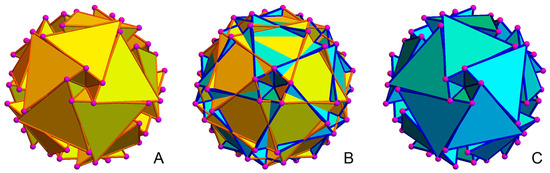
Figure 10.
(A) The right-twisted 20G, (B) the superposition of the left-twisted and right-twisted 20G, and (C) the left-twisted 20G.
3.3. The Possible Mapping of the FIG to the Lattice and the Golden Twisting
One may ask if this new kind of quasicrystal can also be generated by the cut-and-project method, for example, if the FIG can be cut and projected from a higher dimensional crystal lattice. As a matter of fact, we discovered that the FIG is very similar to a 3D quasicrystal that is a golden composition of a 5 or 20 3D tetrahedral () slice of the ESQC [29] (a 4D quasicrystal cut and projected from the lattice). About of the 3D quasicrystal derived from the lattice is a subset of the FIG. This leads us to the investigation of the mapping between the FIG and the lattice. We found two types of mapping that will be discussed in the following three papers in this series of papers, one of which also gives a good explanation from 8D, the golden angle used in the golden composition.
As mentioned earlier, the Fibonacci golden spacing brings the chaotic arbitrary closeness to aperiodic order for both the pentagrid and the icosagrid. We want to argue that the gold twisting used in the gold composition is another operation that makes order emerge from chaos for grids that have five-fold symmetries. Let us first introduce the plane class reduction concept induced by this golden twisting. Regarding tetrahedral packing, the central 20G represents a densely packed cluster of 20 tetrahedra, achieving a maximally reduced set of parallel planes. This arrangement organizes the 20 tetrahedra into a minimum of five crystallographic groups, each consisting of four tetrahedra. Notably, four is the maximal count for vertex-sharing tetrahedral clusters in a crystalline structure that divides evenly into 20, leading to a reduction in plane classes to a minimum of 10. This is in stark contrast to the 70 plane classes found in an evenly distributed vertex-sharing 20-tetrahedral cluster, as shown in Figure 11. A notable transition can be observed in the shift from an evenly distributed vertex-sharing 20-tetrahedral cluster to the 20G. The golden twist repositions the gaps between tetrahedral faces, aligning them with canonical pentagonal cones, one of which is indicated by a white, circled arrow in Figure 11B. These cones serve as a hallmark of the maximal reduction in plane class within the vertex-sharing 20-tetrahedral arrangement. The angle of twist to remove the gaps was shown to equal the angle of rotation into an extra dimension needed to remove the gaps as is typically performed with Regge calculus [32]. The reduction in plane class through golden rotation implies a transition from a state of relative randomness to one of greater order, similar to the effects observed following the Fibonacci spacing of periodic grids, as discussed in the Section 3.2.
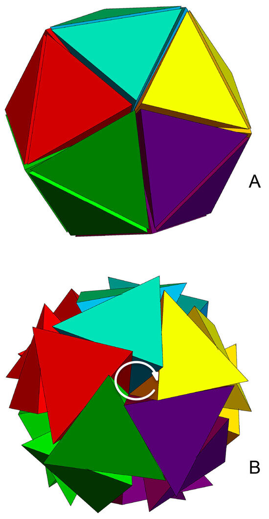
Figure 11.
(A) An evenly distributed vertex-sharing 20-tetrahedral cluster and (B) a twisted 20G with maximum plane class reduction.
Figure 12 shows an example of how the plane reduction by the golden twisting angle brings in order globally. Figure 12A shows 20 slices of ESQC, with their center tetrahedra evenly distributed as shown in Figure 11A. You can see that, globally, the structure has no obvious order. After applying the golden twisting to each slice followed by the center tetrahedron, order starts to emerge. More 20Gs show up and an order forms.
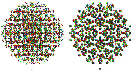
Figure 12.
(A) Evenly distributed slices of the ESQC. (B) After the golden composition twist.
It appears that for multiple grids exhibiting aperiodic symmetry, especially those with five-fold symmetry, an element of the golden ratio is essential for the emergence of order. This includes either golden spacing (as in Fibonacci sequencing) or golden rotation (as seen in golden compositions). The necessity of the golden ratio in five-fold symmetric structures is intuitively understood, given the intrinsic connection of the five-fold symmetry to the golden ratio.
4. Conclusions
We have studied a new type of quasicrystal structures through the Fibonacci multigrid method. By applying Fibonacci spacing to a periodic multigrid, we have successfully transformed conventional grid space into a new quasicrystal type. This new structure diverges from traditional quasicrystals in several key aspects.
Firstly, this method emphasizes grid intersections and segments rather than the usual tiling approach, situating the quasicrystal within the grid space. Secondly, it exhibits a unique form of order. Unlike standard aperiodic order observed in conventional quasicrystals, the Fibonacci multigrid displays a multi-level aperiodicity akin to the layered complexity of fractals. This layered ordering introduces a new dimension to the structural understanding of quasicrystals.
Our exploration included both 2D and 3D models: the Fibonacci pentagrid in two dimensions as well as the Fibonacci tetragrid and the Fibonacci icosagrid in three dimensions. Of particular interest is the Fibonacci icosagrid, which represents a ’golden composition’ derived from the Fibonacci tetragrid. We highlighted the necessity of both golden spacing in Fibonacci spacing and golden rotation in this composition, especially to achieve order in grids with inherent five-fold symmetry.
Furthermore, we briefly mentioned the similarity between the Fibonacci icosagrid (FIG) and another quasicrystal that emerges as a golden composition of five structures, each being a slice of the lattice. This observation has led us to investigate potential mappings between the FIG and the lattice.
The forthcoming series of papers will delve deeper into these mappings, unraveling the complex interplay between Fibonacci-based structures and higher-dimensional lattices. This paper, Part I of the series, introduces an observational connection between the FIG, a 3D quasicrystal, and the lattice. It not only studies a new, unique kind of quasicrystal that is easy to generate through the Fibonacci-spacing method but also possesses a special fractal property in the slow growth of the number of its local vertex configurations. The Fibonacci-spacing and golden rotation methods provide two alternative ways of bringing chaos to order in systems with quasicrystal symmetry; this can have potential applications for system engineering research or quasicrystal growth.
Author Contributions
Initial conceptualization of the tetrahedral packing QC, K.I.; conceptualization and investigation of the Fibonacci spacing and the golden twisting method and the connection between the FIG and the lattice, F.F.; the connection between the divisions of the , K.I.; software and visualization, F.F.; writing, F.F.; supervision, K.I. All authors have read and agreed to the published version of the manuscript.
Funding
This research received no external funding.
Data Availability Statement
The data presented in this study are available on request from the corresponding author due to Privacy reason.
Acknowledgments
The authors would like to thank Raymond Aschheim and Richard Clawson for valuable discussions and insights. We would also like to thank David Chester for help rewriting and editing the paper.
Conflicts of Interest
The authors declare no conflicts of interest.
Abbreviations
The following abbreviations are used in this manuscript:
| FPG | Fibonacci pentagrid quasicrystal |
| FIG | Fibonacci icosagrid quasicrystal |
| FTG | Fibonacci tetragrid quasicrystal |
| ESQC | Elser–Sloane quasicrystal |
| C5C | compound of five cuboctahedra |
| 20G | 20-group of tetrahedra, chirally twisted, with one shared vertex |
| 4G | 4-group of tetrahedrally arranged regular tetrahedra, with one shared vertex |
References
- Shechtman, D.; Blech, I.; Gratias, D.; Cahn, J.W. Metallic phase with long-range orientational order and no translational symmetry. Phys. Rev. Lett. 1984, 53, 1951. [Google Scholar] [CrossRef]
- Steinhardt, P.J. The Second Kind of Impossible; Harvard Science Book Talk; Simon & Schuster: New York, NY, USA, 2019. [Google Scholar]
- Baake, M.; Grimm, U. Aperiodic Order; Cambrage University Press: Cambridge, UK, 2013. [Google Scholar]
- Steinhardt, P.J.; Östlund, S. Physics of Quasicrystals; World Scientific: Singapore; Teaneck, NJ, USA, 1987. [Google Scholar]
- Senechal, M.L. Quasicrystals and Geometry; Cambrige University Press: Cambridge, UK, 1995. [Google Scholar]
- Rivier, N. A botanical quasicrystal. J. Phys. Colloq. 1986, 47, C3-299–C3-309. [Google Scholar] [CrossRef]
- Miekisz, J.; Radin, C. The unstable chemical structure of quasicrystalline alloys. Phys. Lett. A 1986, 119, 133–134. [Google Scholar] [CrossRef]
- Levine, D.; Steinhardt, P.J. Quasicrystals. I. Definition and structure. Phys. Rev. B 1986, 34, 596. [Google Scholar] [CrossRef] [PubMed]
- Henley, C.L. Cell geometry for cluster-based quasicrystal models. Phys. Rev. B 1991, 43, 993. [Google Scholar] [CrossRef] [PubMed]
- Moody, R. (Ed.) The Mathematics of Long-Range Aperiodic Order; Springer: Netherlands, The Netherlands, 1997; Volume 489. [Google Scholar]
- Patera, J. (Ed.) Quasicrystals and Discrete Geometry; American Mathematical Soc.: Toronto, ON, Canada, 1998; Volume 10. [Google Scholar]
- Connes, A. Non-Commutative Geometry; Springer: Berlin/Heidelberg, Germany, 1988. [Google Scholar]
- Socolar, J.E.; Lubensky, T.; Steinhardt, P.J. Phonons, phasons, and dislocations in quasicrystals. Phys. Rev. B 1986, 34, 3345. [Google Scholar] [CrossRef]
- Poon, S. Electronic properties of quasicrystals an experimental review. Adv. Phys. 1992, 41, 303–363. [Google Scholar] [CrossRef]
- Bogomolov, V.N.; Gaponenko, S.V.; Germanenko, I.N.; Kapitonov, A.M.; Petrov, E.P.; Gaponenko, N.V.; Prokofiev, A.V.; Ponyavina, A.N.; Silvanovich, N.I.; Samoilovich, S.M. Photonic band gap phenomenon and optical properties of artificial opals. Phys. Rev. E 1997, 55, 7619. [Google Scholar] [CrossRef]
- Bindi, L.; Kolb, W.; Eby, G.N.; Asimow, P.D.; Wallace, T.C.; Steinhardt, P.J. Accidental synthesis of a previously unknown quasicrystal in the first atomic bomb test. Proc. Natl. Acad. Sci. USA 2021, 118, e2101350118. [Google Scholar] [CrossRef]
- Bindi, L.; Dmitrienko, V.E.; Steinhardt, P.J. Are quasicrystals really so rare in the Universe? Am. Mineral. 2020, 105, 1121–1125. [Google Scholar] [CrossRef]
- Fisher, I.; Islam, Z.; Panchula, A.; Cheon, K.; Kramer, M.; Canfield, P.; Goldman, A. Growth of large-grain R-Mg-Zn quasicrystals from the ternary melt (R= Y, Er, Ho, Dy and Tb). Philos. Mag. B 1998, 77, 1601–1615. [Google Scholar] [CrossRef]
- Nagao, K.; Inuzuka, T.; Nishimoto, K.; Edagawa, K. Experimental Observation of Quasicrystal Growth. Phys. Rev. Lett. 2015, 115, 075501. [Google Scholar] [CrossRef]
- Han, I.; Wang, K.L.; Cadotte, A.T.; Xi, Z.; Parsamehr, H.; Xiao, X.; Glotzer, S.C.; Shahani, A.J. Formation of a single quasicrystal upon collision of multiple grains. Nat. Commun. 2021, 12, 5790. [Google Scholar] [CrossRef]
- Lifshitz, R. The definition of quasicrystals. arXiv 2000, arXiv:cond-mat/0008152. [Google Scholar]
- Else, D.V.; Huang, S.J.; Prem, A.; Gromov, A. Quantum many-body topology of quasicrystals. arXiv 2021, arXiv:2103.13393. [Google Scholar] [CrossRef]
- Baggioli, M. Homogeneous Holographic Viscoelastic Models & Quasicrystals. Phys. Rev. Res. 2020, 2, 022022. [Google Scholar] [CrossRef]
- Baggioli, M.; Landry, M. Effective Field Theory for Quasicrystals and Phasons Dynamics. arXiv 2020, arXiv:2008.05339. [Google Scholar] [CrossRef]
- Amaral, M.; Fang, F.; Hammock, D.; Irwin, K. Geometric State Sum Models from Quasicrystals. Phys. Sci. 2021, 1, 155–168. [Google Scholar] [CrossRef]
- Amaral, M.; Chester, D.; Fang, F.; Irwin, K. Exploiting Anyonic Behavior of Quasicrystals for Topological Quantum Computing. Symmetry 2022, 14, 1780. [Google Scholar] [CrossRef]
- Socolar, J.E.; Steinhardt, P.J. Quasicrystals. II. Unit-cell configurations. Phys. Rev. B 1986, 34, 617. [Google Scholar] [CrossRef]
- Bruijn, N.D. Algebraic theory of Penrose’s non-periodic tilings of the plane. Indag. Math. Proc. 1981, 84, 39–66. [Google Scholar] [CrossRef]
- Elser, V.; Sloane, N.J.A. A highly symmetric four-dimensional quasicrystal. J. Phys. A 1987, 20, 6161–6168. [Google Scholar] [CrossRef]
- Fang, F.; Irwin, K.; Kovacs, J.; Sadler, G. Cabinet of Curiosities: The Interesting Geometry of the Angleβ = arccos ((3ϕ − 1)/4). Fractal Fract. 2019, 3, 48. [Google Scholar] [CrossRef]
- Niu, K.; Fang, M.; Ren, X.; Huang, Z.; Ren, H.; Wu, X.; Sha, W.E.I. Linear and nonlinear spin-orbital coupling in golden-angle spiral quasicrystals. Opt. Express 2020, 28, 334–344. [Google Scholar] [CrossRef]
- Fang, F.; Clawson, R.; Irwin, K. Closing Gaps in Geometrically Frustrated Symmetric Clusters: Local Equivalence between Discrete Curvature and Twist Transformations. Mathematics 2018, 6, 89. [Google Scholar] [CrossRef]
Disclaimer/Publisher’s Note: The statements, opinions and data contained in all publications are solely those of the individual author(s) and contributor(s) and not of MDPI and/or the editor(s). MDPI and/or the editor(s) disclaim responsibility for any injury to people or property resulting from any ideas, methods, instructions or products referred to in the content. |
© 2024 by the authors. Licensee MDPI, Basel, Switzerland. This article is an open access article distributed under the terms and conditions of the Creative Commons Attribution (CC BY) license (https://creativecommons.org/licenses/by/4.0/).