Abstract
CsI(Tl) scintillation screens have been widely applied in X-ray nondestructive testing (NDT) because of their low cost, high scintillation efficiency, and fluorescence guide columnar microstructures. The effect of humidity exposure on the microstructure and photoluminescence properties of polycrystalline CsI(Tl) screens was investigated in this work. The results indicate that the grain diameter of the columnar microstructure increased with increased exposure time in a humid environment. The degree of anisotropy of polycrystalline screens changed from (211) and (310) to (110) orientation with exposure time. FT-IR Spectra of the exposed screens peaked at 3734 cm−1, 3710 cm−1, 3676 cm−1, 3647 cm−1, 3627 cm−1, 3598 c−1, and 3566 cm−1 due to the symmetrical and asymmetrical stretching vibrations of water molecules. In addition, the photoluminescence properties of exposed screens decreased with increased humidity exposure time due to the deliquescence caused by water molecules. After hours of humidity exposure, the photoluminescence and imaging properties of the screens decrease obviously and tend to reduce slowly. The moisture absorption and deliquescence would directly affect the service reliability and the storage lifetime of polycrystalline CsI(Tl) screens.
1. Introduction
Cesium iodide doped with thallium (CsI(Tl)), as a category of X-ray-responsive luminescent materials [1], has been widely used in high-energy physics, non-destructive testing, nuclear medicine, and other fields due to its high scintillation efficiency into visible light, which can be a good match with the spectral sensitivity of Si-based readout arrays (photomultiplier tubes (PMTs) [2,3,4], thin-screen phototransistor (TFT) arrays [5], amorphous Si photodiodes (PDs) [6], complementary metal-oxide semiconductor (CMOS) detectors [7], Si avalanche PDs (APDs) [8], and arrays, or charge-coupled devices (CCDs)) [9] without damaging the Scintillation detectors. As the core component of these instruments, the advantage of CsI(Tl) screens is more pronounced at high spatial resolutions because of the microcrystalline column structures deposited through the vacuum thermal evaporation method, by which the photons can be controlled in the columns reflected by grain boundaries, therefore leading to high spatial resolutions [10,11].
A CsI(Tl) scintillator has outstanding photoluminescence, which occurs when the incoming high-energy X-ray particles collide with ions in CsI(Tl) crystals, exciting the orbital electron of I to a higher energy level, thus forming luminescence centers [12,13]. The electron then returns to its ground energy level by emitting the extra energy as a photon of light in the visible wave range. Its spectrum peaks at 550 nm and has the highest matching relation with the sensitive spectral range of CCD and CMOS [14,15]. When the energy range of incoming particles expands, the properties of radioluminescence, cathodoluminescence, and ionoluminescence in CsI(Tl) scintillators would be displayed [4,16,17,18]. Moreover, polycrystalline CsI(Tl) screens of about seven microns thickness with high performance have been achieved in order to implement the miniaturization and integration of X-ray detectors [19,20,21]. However, the moisture absorptive property of CsI(Tl) crystal would deteriorate its crystalline structure, photoluminescence performance and irradiation imaging quality (a set of performances) [22,23,24]. Therefore, it is of great significance to study the influence of the hygroscopicity ability on the microstructure morphology, crystalline structure, photoluminescence, and irradiation properties of CsI(Tl) screens with micro thicknesses, especially with regard to integrated X-ray detectors applied in extreme environments with high relative humidity.
Among alkali halide scintillators, it is well known that NaI(Tl) is most sensitive to moisture and deteriorates very easily when they are exposed to the atmosphere [25,26]. Studies on the scintillation characteristics of CsI(Na) crystals indicated the performance deterioration of these detectors would degrade sharply in very damp conditions, which was not observed in bulky CsI(Tl) crystals [27,28]. Triloki [29] and Tian [30] investigated CsI(Tl) thick screens after ageing in the atmosphere over a certain period of time and observed the degradation of scintillation performance in CsI(Tl) thick screens. Via atomic force microscope (AFM), Triloki [29] and Xie [31] observed the change trend of the surface profile and microcolumn grain size of CsI(Tl) screens during humid air exposure. Nitti et al. [32,33] studied the influence of humidity exposure on the photocathode stability, which displayed the peak shift of transmittance spectra range from visible wave band to higher energy. It is clear that the humidity exposure would deteriorate the photoluminescence properties of CsI(Tl) crystals, but the influence on the screens with micron thickness has not been investigated systematically and the relevant mechanism is unclear.
In this work, the polycrystalline CsI(Tl) screens with a thickness of 3 μm were successfully deposited, which were exposed in a humidity environment at 40 ± 5% and 80 ± 5% RH for 10 × 24 h and 30 × 24 h, respectively. Meanwhile, the fresh screen and the screen stored in an electronic dry cabinet were also prepared as contrasts. A systematic analysis of the CsI(Tl) screens has been carried out through SEM and XRD; the obtained results show that there appear to be large-sized grains after humidity exposure and the crystalline orientation tends to be a (110) crystal plane. The polar character of the water molecules in the CsI(Tl) screens was verified via the FT-IR Spectra, which are combined to research the influence mechanism of humidity exposure on CsI(Tl) screens. Based on the solvation ability of the polar water molecules and the polarity character of CsI(Tl) ionic crystals, the ions would become unstable and diffuse actively, especially at the grain surface and grain boundary, and ultimately lead to the deterioration of material properties. Subsequently, the photoluminescence spectrum, relative PL intensities, and X-ray irradiation images were improved, respectively. This work demonstrates a series of serious influences of humidity exposure on CsI(Tl) screens of one micron in thickness, and focuses on material interactions and the degradation mechanism within moisture absorptives.
2. Materials and Methods
2.1. Materials
The mixture of CsI and 1.0 mol% Tl powder was purchased from Beijing Hamamatsu Photon Techniques INC and stored in a vacuum-tight container. These compounds were initially characterized via X-ray powder diffraction (XRPD).
2.2. Preparation Methods of the CsI(Tl) Screen
CsI(Tl) scintillator screens were fabricated via vacuum thermal evaporation technique onto the glass substrates from Mo boat with the mixture of CsI and 1.0 mol% Tl powder. The vacuum chamber pressure was kept at around 3 × 10⁻⁵ Pa and the substrate temperature was at room temperature (23 °C). The temperature of the evaporator source was measured with a quartz oscillator during deposition to maintain a uniform designated deposition rate of about 20 Å/s. The cycle was repeated six times and the thickness of these samples was limited to 3 μm through the film thickness monitor. In order to simulate a real environment, such as vacuum packaging, ultra-clean laboratory, and China’s north and south, the samples were exposed at different RH values. A random “fresh” one of the samples was measured immediately to avoid being affected by the laboratory environment. The other five samples were placed in air of different humidities, one of which was stored in an electronic dry cabinet at 1% RH for 30 × 24 h and the remaining four of which were exposed at 40 ± 5% and 80 ± 5% for 10 × 24 h and 30 × 24 h, respectively, wherein the RH values of 40 ± 5% and 80 ± 5% were based on the average humidity in the north and south of China. The humid environment was created in a wet box, whose humidity and temperature could be measured in real time.
2.3. Methods for Evaluation
Morphology, crystal structure, and photoluminescence properties of the CsI(Tl) screen samples were studied via Scanning Electron Microscopy (SEM), X-ray diffraction (XRD), Fourier Transform Infrared Spectroscopy (FT-IR), photoluminescence (PL), and X-ray irradiation. The fresh sample was measured immediately, as soon as it was removed from the coating chamber. The other five samples were measured after humidity exposure.
SEM of CsI(Tl) screen morphology was observed using a QUANTA FEG 450 in a 10 XB metallographic microscope. A high-resolution XRD (Philips PW1710) in CuKα radiation was used to examine the screen crystallographic properties within the analysis range 2θ of 20–90°. FT-IR spectra of screen samples were obtained through A BRUKER TENSOR 27 Fourier Transform Infrared Spectroscopy. The photoluminescence spectra were measured through a spectrometer with Xe lamp excitation and a F900 analyzer (FLSP 920 Edinburgh Instruments Ltd., Livingston, UK), and the excitation light of samples was at a wavelength of 300 nm. The X-ray images of an electronic device including the black-sheathed shell and silicone wires were obtained through the CsI(Tl) screen samples coupled with a CCD imaging system under the X-ray source at 90 kVp acceleration voltage and 30 mA beam current.
3. Results and Discussion
3.1. Microstructure Morphology
The SEM images of the microstructure morphologies of the CsI(Tl) screens exposed at 40 ± 5% RH and 80 ± 5% RH for different times are illustrated in Figure 1. The fresh screen has an even grain diameter of about 1 μm, and there are some pore defects on the surface, as shown in Figure 1a. After being saved in an electronic dry cabinet for 30 × 24 h, the pore defects significantly decrease and even grain diameter does not change significantly (Figure 1b). After being exposed at 40 ± 5% RH for 10 × 24 h, the grain diameter of the screen increases and the micro-columnar grain surfaces curve outward slightly, as shown in Figure 1c. Large-sized grains appear on the surface of the exposed screen and the pore defects on the surface disappear. As the exposure time increases to 30 × 24 h, the grain diameter becomes larger and grain surfaces remain outward (Figure 1d). The morphology of the CsI(Tl) screens exposed at 80 ± 5% RH for 10 × 24 h and 30 × 24 h are shown in Figure 1e,f. Compared to the microstructure morphologies of these samples, the grain size and surface profile are quite different. Under humidity exposure for the same time, it could be observed that average grain size and the amount of the large-sized grains increases and grain surface outline becomes more prominent with the relative humidity doubling from 40 ± 5% RH to 80 ± 5% RH. The same trend held for the screens exposed to humidity air longer at the same relative humidity.
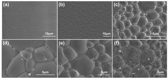
Figure 1.
SEM images of microstructure morphology of CsI(Tl) screens with different exposure times: (a) fresh screen, (b) 1% RH in electronic dry cabinet for 30 × 24 h, (c) 40 ± 5% RH for 10 × 24 h, (d) 40 ± 5% RH for 30 × 24 h, (e) 80 ± 5% RH for 10 × 24 h, (f) 80 ± 5% RH for 30 × 24 h.
The influence mechanism of humidity exposure on the microstructure morphologies of the CsI(Tl) screens was studied. CsI ionic crystal has strong polarity because of the large electronegativity discrepancy between the cesium and iodine (the electronegativity of Cs and I are 0.79 and 2.66), though that difference is slightly decreased by the doping of thallium ions (the electronegativity of Tl: 1.62) [29]. Under humidity exposure, due to the solvation ability of the polar water molecules, the negatively charged oxygen atom and the positively charged hydrogen atom attract the cesium cation and iodine anion, forming the Cs-O and I-H ion–dipole bonds, as shown in Figure 2. And then the original physical configuration of CsI ionic crystal is destroyed. In addition, there are a large number of dangling bonds on the grain surface of the CsI(Tl) screen, attracting the polar water molecules to absorb and bond, thereby decreasing the surface energy [34]. On the other hand, the grain boundaries of microcolumns are aberrant due to the preferred orientation discrepancy of the atoms near the grain boundaries and the microstructure defects, such as vacancy, dislocation, and bond abnormity [26,35,36]. Therefore, grain boundaries are the other position attracting the polar water molecules.
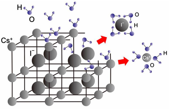
Figure 2.
The model of the absorption and interaction of the polar water molecules at the top surface and grain boundaries of the micro-columns in the CsI(Tl) screens.
The surface and boundaries trend of the microcolumnar grains of CsI(Tl) screens exposed in humid air is illustrated in Figure 3. Due to the surface tension of the water molecules, the surface of columnar grains subjects an additional surface pressure during the bonding process. Under the combination of the additional surface pressure and the grain boundary drag, the micro-column top surfaces become the cycloid profiles, as shown in Figure 3b and curve height would increase as the exposure time prolongs. Meanwhile, the absorbing and diffusing of the free-polar water molecules along with the grain boundaries could decrease the diffusion activation energy further and break the chemical potential balance among grains. Based on the Young–Laplace equation, the convex side of the grain boundary always has a higher chemical potential than the concave side [37,38]. The chemical potential gradient causes the atoms crossing the grain boundary from the convex side to the concave side, and thus the boundaries would migrate in the direction of the grain center with a small curvature radius that eventually leads to the large-sized grains with the concave boundaries growing larger at the expense of the adjacent small grains during the recrystallization process, which is called the engulfment effect, as shown in Figure 3c. Therefore, there appear to be some oversized grains, as shown in Figure 1b,c.
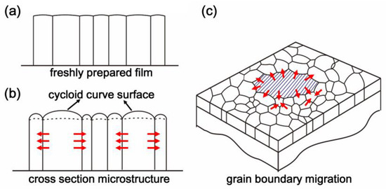
Figure 3.
The change trends of the microcrystalline columns in CsI(Tl) screens during the prolonged exposure to the humid air: (a) freshly prepared screen; (b,c) screen exposed the humid air.
3.2. X-ray Diffraction Patterns
As illustrated in Figure 4, the crystal structure of the CsI(Tl) screens exposed to the humid air at different times was investigated via XRD, in which all diffraction peaks of the six screens match those of cubic crystal structured CsI (PDF#77-2185). Figure 4a depicts the XRD pattern of the freshly prepared CsI(Tl) screen, with great diffraction intensities at the peaks (211) and (310). After being stored in an electronic dry cabinet for 30 × 24 h, the orientation of the screen changes toward the (200) and (310) lattice planes, as shown in Figure 4b. For the CsI(Tl) screens exposed to the humid air (Figure 4c–f), the (110) diffraction peak becomes the strongest, which results from the type-B2 CsCl crystal structure of CsI crystal and the minimum surface energy of the (110) lattice plane. Additionally, there are new orientation relationships in different relative humidity. Under the humidity of 40 ± 5% RH, the lattice orientation of new grains migrates from (211) and (310) lattice planes to (110), (200), (211), (220), (310), and (332), which is consistent with the XRD spectrum of PDF#77-2185. As the relative humidity increases to 80 ± 5% RH, the new orientation relationship is the combination of (110) and (211) lattice planes. In comparison, the changing trend of grain orientation to the crystal plane with low energy is slower under relatively low humidity. Based on the rule of minimum interfacial free energy change, the grain boundaries would migrate toward the crystal plane with the minimum energy required [39,40].
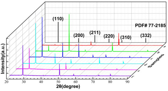
Figure 4.
XRD pattern of CsI(Tl) screen: (a) freshly prepared, (b) 1% RH in electronic dry cabinet for 30 × 24 h, (c,d) exposed to 40 ± 5% humid air 10 × 24 h and 30 × 24 h, (e,f) exposed to 80 ± 5% humid air 10 × 24 h and 30 × 24 h.
3.3. Fourier Transform Infrared Spectroscopy
FT-IR spectra of the CsI(Tl) screens with different exposure times at 40 ± 5% RH are shown in Figure 5 for research on the states of polar water molecules in CsI(Tl) screens. The IR spectra of these CsI(Tl) screens showed peaks at the ranges of 3662–3775 cm−1 and 3560–3650 cm−1, corresponding to the symmetric and antisymmetric stretching vibration absorptions (ν3 and ν1) of the hydroxyls of free water molecules, centered at 3756 cm−1 and 3652 cm−1 [41]. For the “fresh” CsI(Tl) screen, there were only some burrs at the wavenumber ranges of the hydrogen bonds, which was caused by the free water molecules during performance testing, as shown in Figure 5a. Figure 5b demonstrates the screen stored in an electronic dry cabinet for 30 × 24 h; the rangeability of the curve is little changed. After the screens are exposed in a humid environment, the absorption peaks are distinct. With the prolonged exposing time and the RH value increasing, the peak intensities are higher, as shown in Figure 5c–f. This suggests that the thickness of the water molecular layer absorbed at the screen surface and grain boundaries is very thin. Besides, there are no absorption peaks corresponding to the hydrogen bonds among the water molecules at the wavelength range of 3230–3550 cm−1 [34], which is because the hydrogen bonds rupture during the ionic solvation process of water molecules. The missing peaks indicate the characteristics of the water molecules absorbed in the screens that approach the free water further.
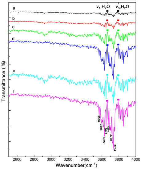
Figure 5.
Infrared transmittance graphs of CsI(Tl) screen: (a) freshly prepared, (b) 1% RH in electronic dry cabinet for 30 × 24 h, (c,d) exposed to 40 ± 5% humid air 10 × 24 h and 30 × 24 h, (e,f) exposed to 80 ± 5% humid air 10 × 24 h and 30 × 24 h.
As shown in Figure 5, the absorption peaks corresponding to ν3 and ν1 of the water molecules split into several peaks at 3734 cm−1, 3710 cm−1, 3676 cm−1, 3647 cm−1, 3627 cm−1, 3598 cm−1, and 3566 cm−1 for all exposed screens. By comparing the spectrum curves of samples exposed at 40 ± 5% RH and 80 ± 5% RH, it is clear that the increasing intensity of the absorption peaks and the peak splitting are more apparent as the relative humidity doubled. This might be due to the combined effect of the hydroxyl affected by the ion-dipole bonds and dangling bonds at the micro-column top surfaces [42]. During the formation of the I-H ion–dipole bond, the electron cloud density of the hydroxyl moves toward the iodide ion, which leads to the shifting of the hydroxyl vibration frequency to the lower wavenumber. Furthermore, the interaction between the water molecules absorbed at the column surfaces could also lead to a similar shifting of the hydroxyl vibration frequency.
3.4. Photoluminescence and Imaging Properties
RL spectra comparison of the six CsI(Tl) screens excited by 300 nm and their relative intensities are shown in Figure 6 and Figure 7. All spectrum curves are centered at 550 nm, and there is a distinct decrease in relative PL intensity for the screens exposed to humidity. The luminescent spectra were obtained by using excitation at 300 nm wavelength, which displays the absence of any additional lines at selective excitation, as shown in the subfigure of Figure 6. The CsI(Tl) screen storage in an electronic dry cabinet at 1% RH for 30 × 24 h incurs a small PL performance penalty. The intensity of the screen exposed to 40 ± 5% RH for 10 × 24 h is half as likely as the freshly prepared screen, and the decrease tendency is also consistent for the screen exposed to the humid air for 30 × 24 h. As RH increases to 80 ± 5%, the PL intensity decreases even further, which is only one-third of the intensity of the fresh screen for 10 × 24 h. The intensity is even reduced further with exposure time increasing to 30 × 24 h. The great decrease in the relative PL intensities is due to the dissolving of water vapor on CsI(Tl) screens and the consequent re-crystallization would cause further deterioration.
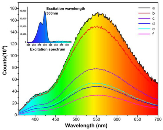
Figure 6.
The photoluminescent spectra of CsI(Tl) screens with different exposure times in humid air: (a) freshly prepared, (b) 1% RH in an electronic dry cabinet for 30 × 24 h, (c,d) exposed to 40 ± 5% humid air 10 × 24 h and 30 × 24 h, (e,f) exposed to 80 ± 5% humid air 10 × 24 h and 30 × 24 h.
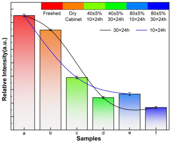
Figure 7.
Relative PL intensities of CsI(Tl) screens with different exposure times in humid air: (a) freshly prepared, (b) 1% RH in an electronic dry cabinet for 30 × 24 h, (c,d) exposed to 40 ± 5% humid air 10 × 24 h and 30 × 24 h, (e,f) exposed to 80 ± 5% humid air 10 × 24 h and 30 × 24 h.
X-ray images of a small electronic device obtained via these CsI(Tl) screens’ irradiation are shown in Figure 8, which shows the wrapped metal part of the electronic device including the main part sheathed in the black plastic shell and the silicone wire part. As shown in Figure 8a,b, the image quality could be maintained for the screen in an electronic dry cabinet. For the screens exposed to humid air of 40 ± 5% RH, their image qualities deteriorate significantly (Figure 8c,d). The deterioration is more serious for the screens at 80 ± 5% RH, which could be observed through the images of silicone wires of the device in Figure 8e,f. The phenomenon indicates that the humid air environment has a great impact on the photoluminescence properties of CsI(Tl) screens, especially for the screens with a thickness of one micron. Therefore, the vacuum packaging and storage mode of CsI(Tl) screens during usage can be taken to protect screens and extend the service life.
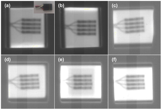
Figure 8.
X-ray images of the electronic device through the screens with different exposure times in humid air: (a) freshly prepared, (b) 1% RH in an electronic dry cabinet for 30 × 24 h, (c,d) exposed to 40 ± 5% humid air 10 × 24 h and 30 × 24 h, (e,f) exposed to 80 ± 5% humid air 10 × 24 h and 30 × 24 h.
4. Conclusions
The effect of relative humidity on luminescence performance in the structured CsI(Tl) screens has been studied. In summary, the influence of humidity exposure on the properties of CsI(Tl) screens is significant. The results show that there are some extra-large-sized grains in the CsI(Tl) screens during humid air exposure, and the top surfaces of micro-columns are presented in the cycloid curve profiles. These phenomena are explained by the absorption and interaction model of the polar water molecules at the top surfaces and grain boundaries of the micro-columns in the CsI(Tl) screens. Meanwhile, there are a set of changes for the CsI(Tl) screens under humid air exposure, such as with regard to their FT-IR spectra, crystal structures, and photoluminescence properties. The crystalline structure presents the (110) orientation with minimum surface energy in the type-B2 CsI structure. FT-IR peaks, splitting at 3734 cm−1, 3710 cm−1, 3676 cm−1, 3647 cm−1, 3627 cm−1, 3598 cm−1, and 3566 cm−1, which corresponds to the absorption peaks of a free water molecule, indicating humidity’s influence on the CsI(Tl) crystal structure. In addition, photoluminescence performance decreases sharply and X-ray image performance deteriorates. Therefore, the packaging and storage of CsI(Tl) screens require special attention for X-ray-imaging applications.
Author Contributions
Conceptualization, L.G. and S.L.; methodology, L.G.; software, B.J.; validation, P.C.; formal analysis, C.T.; investigation, C.T.; resources, P.C.; data curation, S.L.; writing—original draft preparation, L.G.; writing—review and editing, P.C.; visualization, B.J.; supervision, S.L.; project administration, S.L.; funding acquisition L.G. and P.C. All authors have read and agreed to the published version of the manuscript.
Funding
This research was funded by the National Natural Science Foundation of China (62001429, 62122070, 61871351 and 61971381), the Shanxi Provincial Science and Technology Support Project (20210302124191, 20210302124190, 202203021212123), the and Foundation of State Key Laboratory of Dynamic Measurement Technology (2022-SYSJJ-08).
Data Availability Statement
The data that support the findings of this study are available within this article.
Acknowledgments
The authors acknowledge the experimental support of the School of Optoelectronic Information at the University of Electronic Science and Technology of China.
Conflicts of Interest
The authors declare no conflict of interest.
References
- Jana, A.; Cho, S.; Patil, S.A.; Meena, A.; Jo, Y.; Sree, V.G.; Park, Y.; Kim, H.; Im, H.; Taylor, R.A. Perovskite: Scintillators, Direct Detectors, and X-Ray Imagers. Mater. Today 2022, 55, 110–136. [Google Scholar] [CrossRef]
- Mianowska, Z.; Moszynski, M.; Brylew, K.; Chabera, M.; Dziedzic, A.; Gektin, A.V.; Krakowski, T.; Mianowski, S.; Syntfeld-Każuch, A.; Szczesniak, T.; et al. The Light Response of CsI:Tl Crystal after Interaction with Gamma Radiation Study Using Analysis of Single Scintillation Pulses and Digital Oscilloscope Readout. Nucl. Instrum. Methods Phys. Res. A 2022, 1031, 166600. [Google Scholar] [CrossRef]
- Sekiya, H.; Hattori, K.; Kubo, H.; Miuchi, K.; Nagayoshi, T.; Nishimura, H.; Okada, Y.; Orito, R.; Takada, A.; Takeda, A.; et al. Studies of the Performance of Different Front-End Systems for Flat-Panel Multi-Anode PMTs with CsI(Tl) Scintillator Arrays. Nucl. Instrum. Methods Phys. Res. A 2006, 563, 49–53. [Google Scholar] [CrossRef][Green Version]
- Popov, A.I.; Chernov, S.A.; Trinkler, L.E. Time-Resolved Luminescence of CsI-Tl Crystals Excited by Pulsed Electron Beam. Nucl. Instrum. Methods Phys. Res. B 1997, 122, 602–605. [Google Scholar] [CrossRef]
- Nagesh, S.S.; Rana, R.; Russ, M.; Ionita, C.; Bednarek, D.; Rudin, S. WE-G-204-04: Focal Spot Deblurring For High Resolution Amorphous Selenium (ASe) Complementary Metal Oxide Semiconductor (CMOS) X-Ray Detector. Med. Phys. 2015, 42, 3694. [Google Scholar] [CrossRef]
- Tan, H.; DeVol, T.A. Development of a Flow-Cell Alpha Detector Utilizing Microencapsulated CsI:Tl Granules and Silicon PIN-Photodiodes. IEEE Trans. Nucl. Sci. 2002, 49, 1243–1248. [Google Scholar] [CrossRef]
- Chen, H.; Gu, M.; Liu, X.; Zhang, J.; Huang, S.; Liu, B.; Ni, C. Effect of CsI(Tl) Micro-Conical-Frustums on the Performance of the Pixelated CsI(Tl) Scintillation Screen in X-Ray Imaging. Nucl. Instrum. Methods Phys. Res. A 2018, 921, 18–21. [Google Scholar] [CrossRef]
- Li, Y.; Ge, L.; Zeng, G.; Huang, R. Energy Spectrum Response of a CsI(Tl) Detector Read out by an APD. J. Instrum. 2020, 15, T05005. [Google Scholar] [CrossRef]
- Sun, Z.; Gu, M.; Liu, X.; Liu, B.; Zhang, J.; Huang, S.; Ni, C. Influence of Si Wall Thickness of CsI(Tl) Micro-Square-Frustums on the Performance of the Structured CsI(Tl) Scintillation Screen in X-Ray Imaging. Sci. Rep. 2022, 12, 8748. [Google Scholar] [CrossRef]
- Guo, L.; Liu, S.; Wang, T.; Tan, X.; Lu, R.; Zhang, S.; Liu, Y.; Zhong, Z.; Falco, C.M. Growth Mechanism of Polycrystalline CsI(Tl) Films on Glass and Single Crystal Si Substrates. J. Cryst. Growth 2019, 506, 19–23. [Google Scholar] [CrossRef]
- Guo, L.; Liu, S.; Chen, D.; Zhang, S.; Liu, Y.; Zhong, Z.; Falco, C.M. Structure and Scintillation Properties of CsI(Tl) Films on Si Single Crystal Substrates. Appl. Surf. Sci. 2016, 384, 225–229. [Google Scholar] [CrossRef]
- Chernov, S.A.; Trinkler, L.; Popov, A.I. Photo- and Thermo-Stimulated Luminescence of CsI—Tl Crystal after UV Light Irradiation at 80 K. Radiat. Eff. Defects Solids 1998, 143, 345–355. [Google Scholar] [CrossRef]
- Sivasankar, V.S.; Jacobs, P.W.M. Luminescence Spectroscopy of CsI: Tl+. Philos. Mag. B 1985, 51, 479–488. [Google Scholar] [CrossRef]
- Yakovlev, V.; Trefilova, L. A-Luminescence in CsI:Tl Crystal Excited by Pulsed Electron Beam. Nucl. Instrum. Methods Phys. Res. B 2023, 537, 140–146. [Google Scholar] [CrossRef]
- Rogulis, U.; Spaeth, J.-M.; Elsts, E.; Dolgopolova, A. Tl-Related Radiation Defects in CsI:Tl. Radiat. Meas. 2004, 38, 389–392. [Google Scholar] [CrossRef]
- Nikbakht, T.; Vosoughi, Y. Characterization of CsI(Na) Crystal Using Ionoluminescence Microscopy Technique. Nucl. Instrum. Methods Phys. Res. B 2023, 537, 95–99. [Google Scholar] [CrossRef]
- Wu, Z.; Yang, B.; Townsend, P.D. Radioluminescence and Thermoluminescence Properties of X-Ray-Irradiated Pure CsI. J. Lumin. 2008, 128, 1191–1196. [Google Scholar] [CrossRef]
- Leblans, P.; Struye, L.; Elen, S.; Mans, I.; Vrielinck, H.; Callens, F. X-Ray Enhancement of CsI:Eu2+ Radioluminescence. J. Lumin. 2015, 165, 68–76. [Google Scholar] [CrossRef]
- Nagarkar, V.V.; Tipnis, S.V.; Gaysinskiy, V.; Miller, S.R.; Shestakova, I. High-Speed Digital Radiography Using Structured CsI Screens. Nucl. Instrum. Methods Phys. Res. B 2004, 213, 476–480. [Google Scholar] [CrossRef]
- Xie, Y.; Guo, L.; Liu, S.; Wang, Q.; Zhang, S.; Liu, Y.; Zhong, Z. Study on the Effect of Deposition Rate and Concentration of Eu on the Fluorescent Lifetime of CsI: Tl Thin Film. Nucl. Instrum. Methods Phys. Res. A 2016, 858, 18–21. [Google Scholar] [CrossRef]
- Guo, L.; Liu, S.; Chen, D.; Zhang, S.; Liu, Y.; Zhong, Z.; Falco, C.M. Fabrication and Performance of Micron Thick CsI(Tl) Films for X-Ray Imaging Application. IEEE Trans. Nucl. Sci. 2016, 63, 1827–1831. [Google Scholar] [CrossRef]
- Kim, C.; Lee, W.; Melis, A.; Elmughrabi, A.; Lee, K.; Park, C.; Yeom, J.-Y. A Review of Inorganic Scintillation Crystals for Extreme Environments. Crystals 2021, 11, 669. [Google Scholar] [CrossRef]
- Yang, P.; Harmon, C.D.; Doty, F.P.; Ohlhausen, J.A. Effect of Humidity on Scintillation Performance in Na and Tl Activated CsI Crystals. IEEE Trans. Nucl. Sci. 2014, 61, 1024–1031. [Google Scholar] [CrossRef]
- Fedorov, A.; Lebedinsky, A.; Mateychenko, P. Dewetting Behavior of CsI Layers on LiF Substrate. J. Cryst. Growth 2011, 318, 595–598. [Google Scholar] [CrossRef]
- Kerrigan, G.C.; O’Connor, B.H.; Thomas, W.W. The Deterioration in Counting Efficiency of a Scintillation Detector. X-ray Spectrom. 1972, 1, 163–164. [Google Scholar] [CrossRef]
- Fölsch, S.; Henzler, M. Water Adsorption on the NaCl Surface. Surf. Sci. 1991, 247, 269–273. [Google Scholar] [CrossRef]
- Shakhova, K.V.; Panova, A.N.; Goriletsky, V.I.; Prikhod’ko, Y.A.; Gavrylyuk, V.P.; Korsunova, S.P.; Kosinov, N.N. Luminescence and Scintillation Properties of Na-Activated CsI–CsBr Crystals. Radiat. Meas. 2001, 33, 769–771. [Google Scholar] [CrossRef]
- Keillor, M.E.; Cooper, M.W.; Hayes, J.C.; McIntyre, J.I. Degradation of 81 KeV 133Xe Gamma-Rays into the 31 KeV X-Ray Peak in CsI Scintillators. J. Radioanal. Nucl. Chem. 2009, 282, 699–702. [Google Scholar] [CrossRef]
- Triloki; Dutta, B.; Singh, B.K. Influence of Humidity on the Photoemission Properties and Surface Morphology of Cesium Iodide Photocathode. Nucl. Instrum. Methods Phys. Res. A 2012, 695, 279–282. [Google Scholar] [CrossRef]
- Tian, C.; Liu, S.; Xie, Y.; Guo, L.; Zhang, S.; Liu, Y.; Zhong, Z. Influence of the Humid Air on the Structure and Fluorescent Property of CsI:Tl Thin Film. J. Mater. Sci. Mater. Electron. 2019, 30, 7691–7694. [Google Scholar] [CrossRef]
- Xie, Y.; Zhang, A.; Liu, Y.; Liu, H.; Hu, T.; Zhou, L.; Cai, X.; Fang, J.; Yu, B.; Ge, Y.; et al. Influence of Air Exposure on CsI Photocathodes. Nucl. Instrum. Methods Phys. Res. A 2012, 689, 79–86. [Google Scholar] [CrossRef]
- Nitti, M.A.; Senesi, G.S.; Liotino, A.; Nappi, E.; Valentini, A.; Singh, B.K. Influence of the Film Deposition Rate and Humidity on the Properties of Thin CsI Photocathodes. Nucl. Instrum. Methods Phys. Res. A 2004, 523, 323–333. [Google Scholar] [CrossRef]
- Nitti, M.A.; Nappi, E.; Valentini, A.; Bénédic, F.; Bruno, P.; Cicala, G. Progress in the Production of CsI and Diamond Thin Film Photocathodes. Nucl. Instrum. Methods Phys. Res. A 2005, 553, 157–164. [Google Scholar] [CrossRef]
- Foster, M.C.; Ewing, G.E. Adsorption of Water on the NaCl(001) Surface. II. An Infrared Study at Ambient Temperatures. J. Chem. Phys. 2000, 112, 6817–6826. [Google Scholar] [CrossRef]
- Foster, M.; D’Agostino, M.; Passno, D. Water on MgO(100)—An Infrared Study at Ambient Temperatures. Surf. Sci. 2005, 590, 31–41. [Google Scholar] [CrossRef]
- Smart, R.S.C.; Sheppard, N. Infrared and Far Infrared Spectroscopic Studies of the Adsorption of Water Molecules on High-Area Alkali Halide Surfaces. J. Chem. Soc. Faraday Trans. 2 1976, 72, 707–714. [Google Scholar] [CrossRef]
- Vafaei, S.; Wen, D. Modification of the Young-Laplace Equation and Prediction of Bubble Interface in the Presence of Nanoparticles. Adv. Colloid. Interface Sci. 2015, 225, 1–15. [Google Scholar] [CrossRef] [PubMed]
- Moriyama, M.; Matsunaga, K.; Murakami, M. The Effect of Strain on Abnormal Grain Growth in Cu Thin Films. J. Electron. Mater. 2003, 32, 261–267. [Google Scholar] [CrossRef]
- Hoedlmoser, H.; Braem, A.; De Cataldo, G.; Davenport, M.; Di Mauro, A.; Franco, A.; Gallas, A.; Martinengo, P.; Nappi, E.; Piuz, F.; et al. Long Term Performance and Ageing of CsI Photocathodes for the ALICE/HMPID Detector. Nucl. Instrum. Methods Phys. Res. A 2007, 574, 28–38. [Google Scholar] [CrossRef]
- Nitti, M.A.; Cioffi, N.; Nappi, E.; Singh, B.K.; Valentini, A. Influence of Bias Voltage on the Stability of CsI Photocathodes Exposed to Air. Nucl. Instrum. Methods Phys. Res. A 2002, 493, 16–24. [Google Scholar] [CrossRef]
- Engkvist, O.; Stone, A.J. Adsorption of Water on the NaCl(001) Surface. III. Monte Carlo Simulations at Ambient Temperatures. J. Chem. Phys. 2000, 112, 6827–6833. [Google Scholar] [CrossRef]
- McBride, F.; Hodgson, A. Water and Its Partially Dissociated Fragments at Metal Surfaces. Int. Rev. Phys. Chem. 2017, 36, 1–38. [Google Scholar] [CrossRef]
Disclaimer/Publisher’s Note: The statements, opinions and data contained in all publications are solely those of the individual author(s) and contributor(s) and not of MDPI and/or the editor(s). MDPI and/or the editor(s) disclaim responsibility for any injury to people or property resulting from any ideas, methods, instructions or products referred to in the content. |
© 2023 by the authors. Licensee MDPI, Basel, Switzerland. This article is an open access article distributed under the terms and conditions of the Creative Commons Attribution (CC BY) license (https://creativecommons.org/licenses/by/4.0/).