Article

Effect of Machine Pin-Manufacturing Process Parameters by Plasma Nitriding on Microstructure and Hardness of Working Surfaces

by
Włodzimierz Dudziński
1,
Daniel Medyński
1,* and
Paweł Sacher
2
1
Department of Production Engineering and Logistics, Faculty of Technical and Economic Sciences, Sejmowa 5A, 59-220 Legnica, Poland
2
Sacher Company, Ekonomiczna 6, 59-700 Bolesławiec, Poland
*
Author to whom correspondence should be addressed.
Crystals 2023, 13(7), 1091; https://doi.org/10.3390/cryst13071091
Submission received: 6 June 2023 / Revised: 7 July 2023 / Accepted: 11 July 2023 / Published: 13 July 2023

Abstract

:
This work concerns two stages of research into plasma nitriding (change of nitriding steel and modification of nitriding parameters). In the first stage, pins obtained from currently used steel were compared with pins made of an alternative material available on the market, using the same nitriding process parameters. As a result of the metallographic tests carried out, in the first case, the presence of a thin, porous, and heterogeneous nitrided layer or its absence was found, with the core in its raw state and not thermally improved. In the second case, the presence of a nitrided layer of small thickness with noticeable porosity on the surface of the sample was found, but with a core after heat treatment (incorrect process parameters). Therefore, modification of the parameters of the nitriding process was proposed, in terms of a mixture of gases, currents, time, and temperature of the nitriding process. As a result, a satisfactory effective thickness of the nitrided layer was obtained, consisting of a white near-surface zone with ε and ε + γ′-type nitrides with a thickness of 8.7 to 10.2 µm, and a dark zone of internal nitriding with γ′ nitrides. The nitrides layer was continuous, compact, and well adhered to the steel surface. In the core of the samples, the presence of a fine-needle tempering sorbite structure with a small amount of fine bainite, which is correct for the steel after heat treatment and nitriding, was found. The most favorable parameters of the ion nitriding process were gas flow rate (1.5 L/min N; 0.4 L/min H; 0.3 L/min Ar); currents (BIAS—410 V 4.0 A, SCREEN—320 V 4.0 A); time (26 h and 35 min); and temperature (550 °C).

1. Introduction

Both in everyday life and in industry, products that can make our lives easier, better and safer are very important. With this in mind, there is a constant need to improve the approach to production. One aspect of product improvement is the need for increasingly efficient and cost-effective manufacturing methods. To ensure cost-effective production, especially for large-scale industrial processing, this approach requires continuous process improvement. The key in this aspect is surface engineering, which includes the use of traditional and innovative technologies to obtain a product surface with better properties compared to the existing ones [1,2]. One of the methods of improving the surface properties of the product is the treatment of its surface after production, usually aimed at its hardening. The need to harden the surface of materials, especially metals, is now more in demand than ever. This is due to the systematically growing demand for metallic materials that, with high hardness, show high strength, resistance to abrasive wear, and, very importantly, are obtained at reduced production costs. Modern surface-treatment methods most often include chemical vapor deposition (CVD), physical vapor deposition (PVD), cladding, and plasma nitriding [1,2,3,4,5,6].
Nitriding is one such surface-treatment method that is critical to modern industry. It is used in many fields, including machine, automotive, and tool industries [3,7,8,9,10,11,12,13,14,15]. The nitriding process guarantees the improvement of the surface properties, primarily alloy steels intended for nitriding, while maintaining minimum dimensional tolerances and high abrasion resistance. In addition to increasing the surface hardness, wear resistance, and corrosion resistance, nitriding can lead to an improvement in the fatigue strength of the component. This is possible due to the formation of appropriate phases with increased volume, causing the occurrence of compressive stresses in the surface layer.
This is possible because iron in Fe–C alloys occurs in various allotropic forms, which, combined with appropriate alloy additions, favors the formation of phases strengthening their surface in the nitriding process [16,17,18,19]. Up to a temperature of 912 °C, the Feα variety occurs, crystallizing in the BCC lattice. Between the temperatures of 912 and 1394 °C there is a Feγ variety crystallizing in the FCC lattice, and in the temperature range of 1394 to 1538 °C, there is a high-temperature Feδ variety crystallizing in the BCC lattice. The phases occurring in the iron–nitrogen system are shown in the phase equilibrium diagram in Figure 1.
The graph shows that the solubility of nitrogen in Feα is low and reaches a maximum at 590 °C. At this temperature, the solubility is 0.10% and decreases rapidly with decreasing temperature, so that at 200 °C it is only 0.004%. This interstitial solution of nitrogen in the iron is called nitrogen ferrite.
There are two interstitial vacancies in the Feα lattice where nitrogen can be located. The radius of octahedral and tetrahedral vacancies is 0.019 nm and 0.052 nm, respectively [11]. Even though the radius of the N atom is 0.07 nm, it was found that it is in smaller octahedral vacancies in the Feα lattice, thus causing the expansion of the Feα lattice, an increase in internal stresses, and solution strengthening [20,21,22,23].
The solubility of nitrogen In Feγ is much higher, and this solution, called nitrogen austenite, is stable only at temperatures higher than 590 °C. The greatest solubility of nitrogen in Feγ is 2.80% at 650 °C, and then decreases to 2.35% at the eutectoid temperature. Nitrogen austenite with such a composition decomposes eutectoidly into a mixture of Feα(N) nitrogen ferrite and the γ′ phase. This eutectoid, formed during slow cooling, is called braunite. By rapid cooling, however, nitrogen austenite can be supercooled to temperatures at which nitrogen martensite is formed as a result of diffusion-free transformation. The temperature Ms (martensite start) in this case is lower than in steels and, in the alloy with eutectoid composition, it is only 35 °C.
The γ′ phase is a solid solution based on iron nitride Fe4N with a narrow homogeneity range. This phase is stable up to 680 °C and then changes to the hexagonal ε phase, which is a solid solution with a wide range of homogeneity. Like nitrogen austenite, the ε phase containing 4.55% nitrogen decomposes at 650 °C into a eutectoid mixture of γ and γ′ phases.
The iron nitrides show low durability and decompose at higher temperatures, which can be seen in the example of the γ′ phase. Due to this low stability, iron nitrides coagulate rapidly, even at low temperatures. The consequence of this is the low hardness of the surface of nitrided objects made of unalloyed steel because the dispersion of the formed nitrides quickly disappears.
More durable, and therefore less prone to coagulation, nitrides form nitrogen with transition metals that are components of alloy steels. These can be, for example, chromium nitrides CrN and Cr2N and molybdenum nitrides MoN, titanium nitrides TiN, or others. The most durable AlN nitrides are formed by aluminum and therefore are used in special grades of steel intended for nitriding. Apart from other alloying additives, this element is also used.
The structure of the diffusion layers formed depends primarily on the nitriding temperature, the chemical composition of the nitriding atmosphere, and the chemical composition of the material of the nitrided objects.
As already mentioned, the nitrided sample is characterized by increased surface hardness, increased wear resistance, high fatigue strength, increased corrosion resistance, and high dimensional stability [1,24,25,26,27,28,29,30,31,32,33,34,35,36,37]. This is possible because a sufficiently high concentration of nitrogen on the steel surface determines the formation of Fe–N phases. If the concentration of nitrogen increases sufficiently, a layer of these compounds with very high hardness forms on the surface. Below this layer, a diffusion zone is formed, consisting of nitrogen in the interstitial solid solution with fine precipitations of alloy nitrides [1,24]. This mechanism of precipitation hardening of the diffusion zone depends largely on the number of elements that favor the formation of nitrides and on the concentration of nitrogen itself [38]. A simplified cross-sectional diagram of a typical nitrided sample is shown in Figure 2. The diffusion zone consists of interstitial nitrogen dissolved in the Feα lattice and Fe alloy carbonitrides [39,40,41]. It has been shown that the high surface hardness obtained as a result of nitriding results from the precipitation of fine-grained alloy carbonitrides [42,43,44]. The latter is a consequence of the presence of strongly nitride-forming elements in the steel substrate, such as Al, Cr, Mo, Ti, Mn, Si, and V [43,44,45]. The hardness in the diffusion zone depends on the type and number of alloying elements in the steel [38,46]. In addition, in high-alloy steels, there is a reduction in the hardening depth after nitriding treatment due to the precipitation of alloy nitrides, which additionally limits the diffusion of nitrogen to the substrate [47].
Plasma nitriding is one of the modern techniques of thermo–chemical treatment, which is usually carried out with the use of nitrogen and hydrogen [48,49,50,51,52]. The process is carried out under reduced pressure where a voltage is applied between the samples and the walls of the furnace. A glow discharge with a high level of ionization (plasma) is generated around the part [48,49]. In the area of the workpiece surface that is directly bombarded with ions, nitrogen-rich nitrides form and break down, releasing active nitrogen to the surface. The ability to adjust the degree of cathodic sputtering, the selection of the appropriate current–voltage characteristics, and the ability to increase or decrease the pressure in the working chamber enables the formation of the structure of nitrided layers [53]. Plasma nitriding makes it possible to modify the surface according to the desired properties [53,54,55,56]. By adjusting the gas mixture (proportions), it is possible to obtain tailored layers and hardness profiles, from a surface free of a layer of low nitrogen compounds and up to 20 microns thick, to a layer containing nitride compounds and a solid solution diffusion zone. The wide temperature range allows many applications beyond the possibilities of gas or salt bath processes.
Traditional nitriding techniques most often lead to the formation of defects, such as the formation of brittle surface layers, and the effect of non-uniform edges. To eliminate these problems, especially in the case of plasma nitriding, appropriate nitriding furnaces have been developed [57,58,59]. One of the recent innovations in this field was the introduction of the innovative technology of Active Screen Plasma Nitriding (ASPN) [56,57,58,59]. ASPN nitriding ensures the uniform formation of nitrides that reflect the shape of the workpiece. This effect is achieved by glowing nitrogen-activating plasma on the mesh as well as on the nitrided detail, which guarantees no damage or burns caused by oversized plasma discharges on the detail. This minimizes the risk of damage to the elements subjected to electric arc treatment and uneven heating of elements of different dimensions, and removes or minimizes the polarization voltage, which is applied to the treated elements in traditional plasma nitriding [59,60,61,62].
This work is the result of research and development activities carried out as part of the project entitled Regional Operational Program for the Lower Silesian Voivodeship for the years 2014–2020. As part of the project, actions were taken to modify the parameters of the technological process for the production of machine pins to improve the surface properties of the product. The research was carried out in two stages. In the first stage, they consisted of comparing the process from the point of view of the currently used steel with an alternative material, while maintaining the previously used parameters of the nitriding process. In the second stage, the parameters of the plasma nitriding process were modified.

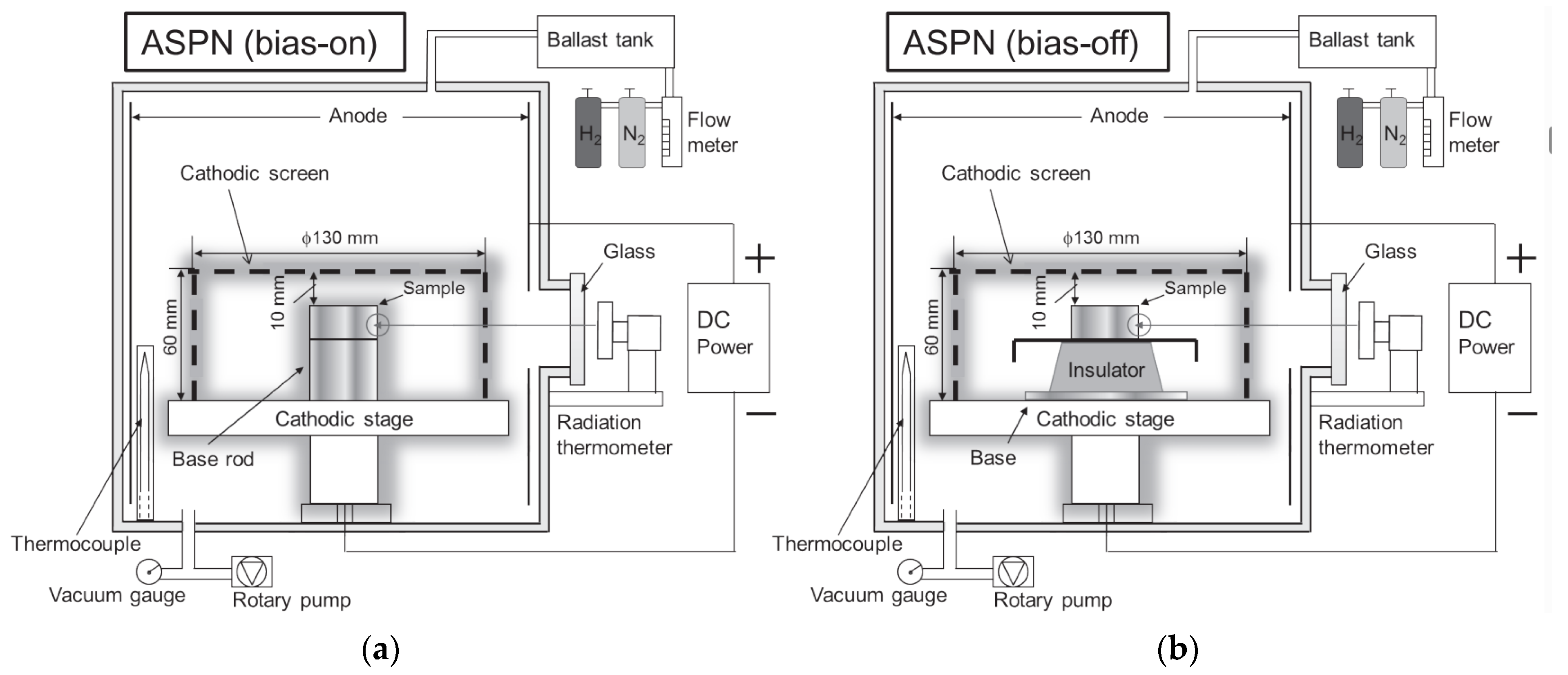
2. Materials and Methods

The samples taken from the pins, which were plasma nitrided with Nitro-Tool technology in a vacuum furnace, using the ASPM method, were tested. Figure 3 shows a diagram of a vacuum furnace for nitriding using the ASPN method. During the tests, the ASPN nitriding method with active BIAS was used to obtain an even coverage with the nitrided layer.
In the first stage of the research, samples taken from pins currently manufactured by the Sacher Company, made of 38HMJ steel (designation according to the withdrawn PN—89/H84030.03 standard), in the state before and after the application of the plasma nitriding process, were tested. The parameters of the nitriding process typical for the company were used: gas flow rate (1.3 L/min N; 0.7 L/min H; 0.2 L/min Ar); currents (BIAS—420 V 5.0 A, SCREEN—320 V 3.0 A); time (26 h and 35 min); and temperature (510 °C).
As a result of the microscopic examination of samples subjected to heat–chemical treatment with the ion nitriding method, according to the parameters mentioned above, the presence of a thin, porous, and non-homogenous nitrided layer (or its absence) and a diffusion layer of small thickness was found on the surface of the sample with a raw, not thermally improved core.
After analyzing the obtained results, the possibility of using modern grades of steel, e.g., 33CrMoV12—9 or 32CrAlMo7—10 (designation according to PN EN ISO 683—5:2021—10) was proposed as an alternative to the currently used steel used for the production of pins. Due to the unavailability of these materials, 42CrMo4 steel (designation according to EN ISO 683—1:2018—09) was used in the tests. After machining, the pins were subjected to the nitriding process, each time using the same process parameters as in the case of the first thermo–chemical treatment.
However, these actions did not bring the desired effect. Therefore, steps were taken to modify the parameters of the nitriding process. Thus, four test trials were carried out. Each time a different process parameter was changed (gas mixture, currents, time, and temperature), with the others returning to their initial values. Individual parameters were changed in the following ranges: gas flow rate (1.3–1.5 L/min N; 0.4–0.7 L/min H; 0.2–0.3 L/min Ar); currents (BIAS: 410–440 V 4.0–5.0 A, SCREEN: 320–330 V 3.0–4.0 A); time (from 26 h and 35 min to 30 h and 38 min); temperature (510–550 °C).
In each case, the pins (dimensions ∅ 35 × 75) were produced using CNC machines: HASS SL—20 (Hass Automation Inc., Oxnard, CA, USA) and HASS VF5 (Hass Automation Inc., Oxnard, CA, USA). The pins were then subjected to ion plasma nitriding using a Nitro-Tool furnace (AMP Heat Treatment Technologies Company, Świebodzin, Poland).
Test samples were cut using a Secotom precision cutting machine (Struers, Copenhagen, Denmark) and then embedded. A grinding and polishing machine by LaboSystem (Struers, Copenhagen, Denmark) was used for grinding and polishing the specimens.
The metallographic tests consisted of the determination of the chemical composition using the spectral method using a GDS 750 QDP glow discharge analyzer. During the analysis, the following parameters were used to ionize the inert gas: U = 1250 V, I = 45 mA, 99(.9)% Ar (Leco, St. Joseph, MI, USA). The obtained results were the arithmetic mean of at least five measurements and the X-ray energy dispersion spectroscopy method (SEM Quanta 250 FEI with EDS detector by Oxford Instruments). The WDS by Oxford Instruments was also used for comparative purposes (for carbon and nitrogen content); measurement of the hardness distribution on the cross-section was carried out using a Vickers hardness tester MMT—X7B (Matsuzawa Co., Tokyo, Japan) under conditions compliant with PN EN ISO 6507—1:2018—05, as well as analysis of the microstructure of the core, nitrided layer and determining the thickness of the layer nitrided, using an Eclipse MA—200 metallographic microscope (Nikon, Tokyo, Japan), under conditions compliant with PN—82/H— 04550. Microscopic observations were carried out on samples non-etched and etched with nital-Mi1Fe (5 % alcohol solution HNO4). Nital etching made it possible to visualize the microstructure of individual zones, i.e., the surface containing characteristic types of nitrides and the core without nitrides.

3. Results and Discussion

3.1. Testing of Currently Produced Pins—38HMJ Steel

In the first stage, metallographic tests were carried out on samples taken from pins made of 38HMJ steel (outdated designation according to the withdrawn PN—89/H84030.03 standard), delivered by the company before and after the nitriding process. The results of the analysis of chemical composition obtained by the GDS method of the base steel samples for nitriding are presented in Table 1.
Based on the analysis of the chemical composition, it was confirmed that the closest equivalent of the material from which the samples were made is 38HMJ steel (according to withdrawn PN—89/H84030.03).

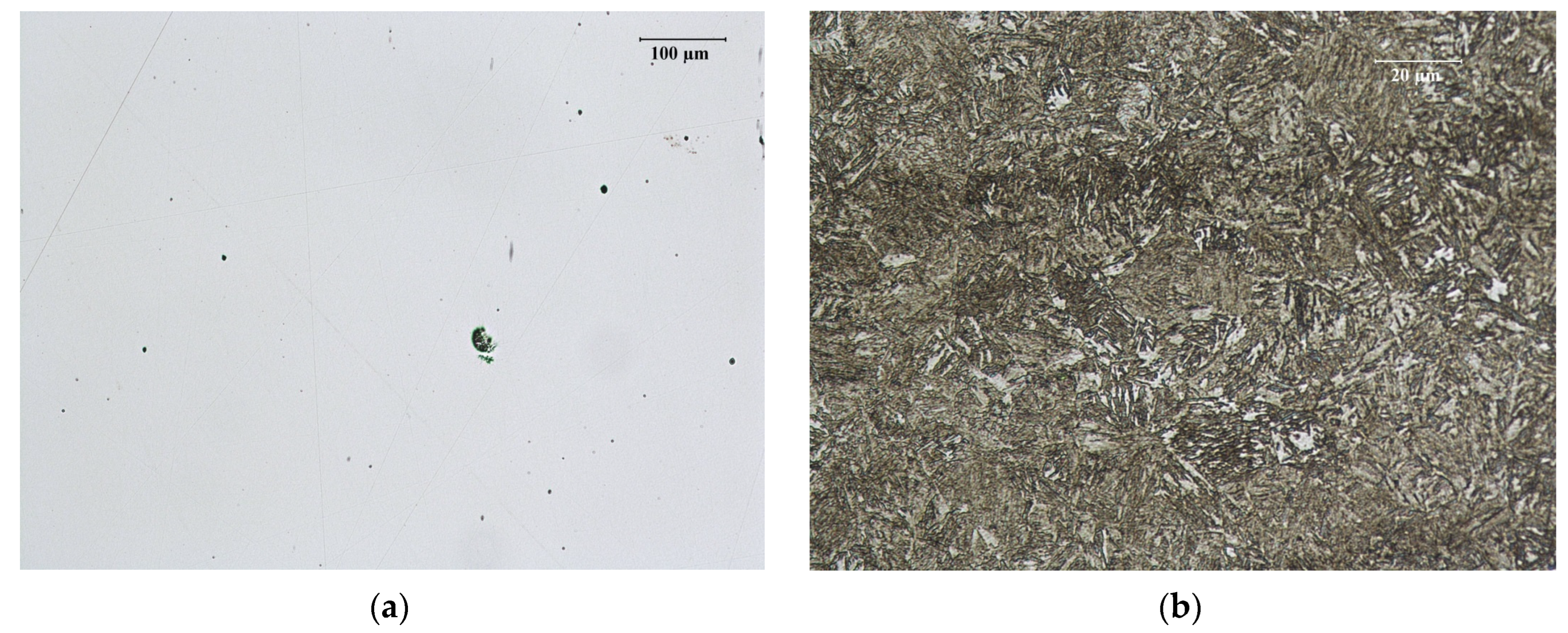
3.1.1. Microscopic Observations of Pins in Raw State

Microscopic observations of non-etched samples taken from pins in their raw state showed the presence of an increased number of non-metallic inclusions, mainly in the form of oxides and brittle silicates (Figure 4a). This indicates the low quality (metallurgical purity) of the tested material. After etching the reagent, a very finely dispersed, partially banded pearlitic structure with grains of free ferrite was found (Figure 4b).
This structure is typical for materials cooled from hot working temperatures (raw state) and is an incorrect structure, as it is the initial structure for steel before the nitriding process. It can cause a significant reduction in strength properties, and in particular cause cracks and chipping, and reduce the fatigue resistance of nitrided details.
In this case, it can be stated that no thermal improvement procedure was applied before the ion nitriding process.

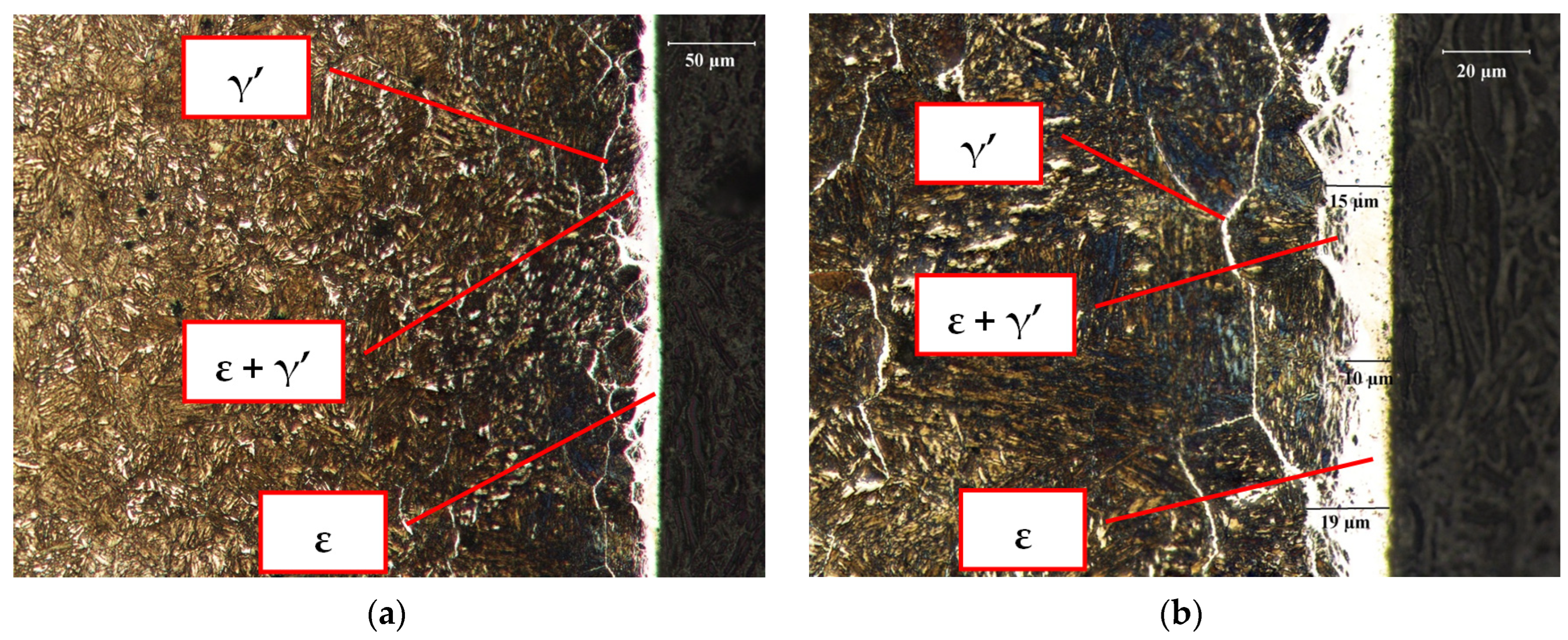
3.1.2. Microscopic Observations of Pins after Nitriding

Based on the conducted microscopic examinations of nitral-etched samples after nitriding, the presence of a ferritic-pearlitic banded structure, typical of the raw state after hot plastic working, was found in the core (Figure 5). This indicates that the heat treatment required before the nitriding process was not applied. The nitrogen content on the surface of the samples after nitriding was an average of 8.50 %mass (EDS and WDS for comparison).
In the surface zone, a nitrided layer was found with a total metallographic thickness of about 0.2 mm (Figure 6), consisting of a very thin white near-surface layer with ε and ε+γ′-type nitrides, 5 to 10 µm thick, and a dark nitriding zone with the γ′ nitride lattice forming a lattice on the former austenite grain boundaries.
Changes in the thickness of the nitride layer ε and ε+γ′ in the range from 2 to 5 µm and porosity features were observed locally (Figure 6a). In addition, a continuous network of nitrides distributed γ′ along the grain boundaries of the former austenite was found. The transition zone from the nitrided layer to the core has the correct structure. Summing up, the obtained structure is incorrect, showing a high tendency toward cracks and chipping of the surface layer during operation.
On the other hand, a dendritic bainitic structure was found in the core of the samples with precipitates of sorbite and troostite in the interdendritic spaces. This is an unacceptable defect, indicating a complete lack of application of thermal improvement after the plastic working process before the nitriding process or the use of incorrect technology in the thermal improvement process. It should be mentioned that the thickness of the nitrided layer should be from approx. 0.5 mm to approx. 0.7 mm. The small thickness of the nitrided layer requires a uniform, hard and resilient substrate, protecting the above-mentioned layer against its collapse and chipping under the action of local pressures.
In addition, it was found that in many places around the circumference of the sample, the nitrided layer was irregular, thicker in some places—place No. 1, thinner in some places—place No. 2 in others (Figure 7) or there is no such layer (Figure 8).

3.1.3. Pin Hardness Measurements before and after Nitriding

Hardness measurements were carried out using the Vickers method in conditions compliant with PN EN ISO 6507—1:2018 on the cross-section of the samples in the plane perpendicular to the nitrided surface in the cores of the samples taken from the pins before and after nitriding. A Matsuzawa hardness tester was used with a load of 1 kg (9807 N) operating for 15 s.
The average hardness of the base material in the core of the sample taken from the pin as supplied was found to be 255.8 HV1. The hardness in the core of the sample after the nitriding process does not show significant differences and amounts to 349.8 HV1, respectively.
In addition, measurements of the hardness distribution under the surface of the nitrided layer were made in two places on the sample after nitriding, using a Matsuzawa hardness tester with a load of 0.5 kg (4.904 N).
Determination of the thickness of the nitrided layer by measuring the hardness distribution was made in accordance with the PN—82/H—04550 standard. Hardness measurements were made along a line perpendicular to the surface of the sample at intervals of 50 µm. The measurement results are summarized in Table 2 and Table 3.
As a result of hardness measurements, it was found that in the sample after nitriding in place No. 1, the effective thickness of the nitrided layer calculated up to the hardness of 500 HV0.5 is 0.13 mm (130 µm), and the maximum hardness of 732 HV0.5 in place No. 1 occurs at a distance of up to 0.05 mm (50 µm) below the sample surface. The hardness at a distance of approx. 0.2 mm from the surface is 373 HV0.5.
In the sample after nitriding in place No. 2, the effective thickness of the nitrided layer calculated up to the hardness of 500 HV0.5 is 0.18 mm (180 µm), and the maximum hardness of 761.2 HV0.5 also occurs at a distance of up to 0.05 mm (50 µm) below the surface of the sample. The hardness at a distance of about 0.2 mm from the surface is 396 HV0.5.
The obtained results indicate that 38HMJ steel should not be used for nitriding. It was proposed to use modern steel grades intended for nitriding, e.g., 33CrMoV12—9 or 32CrAlMo7—10 (designation according to PN EN ISO 683-5:2021—10), and in the absence of their availability, the use of 42CrMo4 steel (designation according to EN ISO 683-1: 2018—09).

3.2. Study of Pins Manufactured from Alternative Steel—42CrMo4

Due to the unavailability of 33CrMoV12—9 and 32CrAlMo7—10 steel, 42CrMo4 steel was used.

3.2.1. Pins before Nitriding

As a result of microscopic examinations carried out in the longitudinal and transverse direction to the direction of machining of the pins in the non-etched state, a small number of non-metallic inclusions was found, mainly in the form of point oxides, unevenly distributed (Figure 9a). After etching, a partially banded bainite structure of a dendritic character was found, with precipitates of sorbitol and troostite in the interdendritic spaces (Figure 9b).

3.2.2. Pin Surface after Nitriding

The analysis of the results of EDS (WDS analysis was used for comparison purposes for carbon and nitrogen) measurements made on the cross-section of the correctly nitrided samples showed the highest nitrogen saturation on their surface and a systematic decrease in the concentration of nitrogen towards the core, unlike the other elements (Figure 10).
Based on the conducted microscopic examinations, the presence of a nitrided layer with a metallographic thickness of approx. 0.3 mm was found (Figure 11). This layer consists of a white near-surface zone with nitrides of the ε and ε+γ′-type with a thickness of 10 to 19 µm, and a dark zone of internal nitriding with a network of γ′ nitrides forming a mesh on the boundaries of former austenite grains.
In addition, it was found that in some places around the circumference of the sample, the nitrided layer was non-uniform and porous (Figure 11a and Figure 12). Changes in the thickness of the nitride layer ε and ε+γ′ in the range of 4 to 7 µm and porosity were observed locally. A lattice of γ′ nitrides distributed along the grain boundaries of the former austenite was also found. Moreover, the lack of an internal nitriding transition zone was observed. Locally, the hardness of the core was low and amounted to 320 HV1. It is an incorrect structure, showing a high tendency towards the cracking and chipping of the surface layer during operation.
In the core of the sample, a dendritic bainitic structure was found with precipitates of sorbite and troostite in the interdendritic spaces, typical for materials cooled quickly from hot working temperatures (typical for the raw state QT). This is an unacceptable defect, indicating a complete lack of application of the thermal improvement treatment after the plastic working process before the nitriding process or the use of an incorrect technology in the thermal improvement process.
As mentioned earlier, the thickness of the nitrided layer should be from about 0.5 mm to about 0.7 mm. The small thickness of the nitrided layer requires a uniform, hard and resilient substrate, protecting the above-mentioned layer against its collapse and chipping under the action of local pressures.

3.2.3. Measurements of Hardness of Samples Core after Nitriding

Core hardness measurements were made on the cross-section of the sample. The tests were carried out using the Vickers method in conditions compliant with PN EN ISO 6507—1:1999. As before, a Matsuzawa hardness tester with a load of 1 kg (9.807 N) operating for 15 s was used. As a result of the hardness measurements of the material in the core of the sample after the nitriding process, it was found that the average hardness of five measurements is 436.5 HV1.

3.2.4. Determination of Nitrided Layer Thickness

Determination of the thickness of the nitrided layer by measuring the hardness distribution was made in accordance with the PN—82/H—04550 standard. Hardness measurements were carried out using the Vickers method in conditions compliant with PN EN ISO 6507—1:2018 on the cross-section of the sample in the plane perpendicular to the nitrided surface. A Matsuzawa hardness tester was used with a load of 0.5 kg (4.904 N) operating for 15 s. Hardness measurements were made along a line perpendicular to the surface at intervals of 50 µm.
As a result of the hardness measurements, it was found that the effective thickness of the nitrided layer calculated to a hardness of 500 HV0.5 is 0.35 mm. The results of hardness measurements are summarized in Table 4 and additionally in the form of a graph in Figure 13.
Referring to Section 3.2.2, it was found that reducing the nitrogen content from the surface towards to core of the samples caused changes in the microstructure from the formation of a white surface layer of ε-type nitrides, through a diffusion layer of ε+γ’-type nitrides, to the dark zone of γ’-type nitrides. This, in turn, resulted in a successive decrease in hardness, caused by a change in the types of nitrides in individual zones from the surface to the pin core.
As a result of the analyses carried out, it was found that the change in the material of 38HMJ steel to 42CrMo4 steel brought some improvement, but not as much as could be obtained using modern grades of steel, specially dedicated to the nitriding process.
To obtain a greater thickness of the nitrided layer, changing the parameters of the ion nitriding process was proposed, e.g., extending the nitriding time, changing the chemical composition of the nitriding atmosphere in the furnace, changing the BIAS potential, or possibly increasing the nitriding temperature. Before nitriding, it was necessary to carry out heat treatment, i.e., hardening from 880 °C in oil and tempering at 560 °C/1 h.

3.3. Testing of Samples Taken from Pins Made of Nitrided 42CrMo4 Steel at Various Process Parameters

Before nitriding, the pins were subjected to heat treatment, i.e., hardening from 880 °C in oil and tempering at 560 °C/1 h. Then, samples taken from the pins after the nitriding process carried out in accordance with the parameters given in Table 5 were examined.
As a result of the conducted microscopic observations of the samples etched with nital, it was found that in the core of all samples, there is a structure of fine-needle tempered sorbite with a small amount of fine bainite with a hardness of 330 to 366 HV0.5. This structure is typical for 42CrMo4 steel in the heat-treated state after the ion nitriding process and is correct (Figure 14, Figure 15, Figure 16 and Figure 17).

3.3.1. Sample No. 1—Microscopic Observations

In sample No. 1, a nitrided layer with a metallographic thickness of approx. 0.3 mm was found, consisting of a white near-surface zone with ε and ε + γ′ nitrides with a thickness of 8.7 to 10.2 µm and a dark internal nitriding zone with γ′ nitrides. The layer of nitrides ε and ε + γ′ is continuous, compact and adheres well to the steel substrate.
In the core of the sample, there is a structure typical of fine-needle sorbite tempering, typical of 42CrMo4 grade steel in the tempered state (Figure 14). The structure of the heat–chemically treated layer is typical for glow-nitrided layers and is correct.
Figure 14. Nitrided layer in sample No. 1. Visible bright layer of ε, ε + γ′-type nitrides and a dark internal nitriding zone with γ′ nitride precipitates. Etched state.
Crystals 13 01091 g014

3.3.2. Sample No. 2—Microscopic Observations

In sample No. 2, the presence of a nitrided layer with a metallographic thickness of approx. 0.1 mm was found, consisting of a white near-surface zone with ε and ε + γ′ nitrides with a thickness of 4.2 to 5.6 µm and a dark zone of internal nitriding with γ′ nitrides. The layer of nitrides ε and ε + γ′ is continuous, compact and adheres well to the steel substrate.
In the core of the sample, there is a typical structure of fine-needle tempered sorbite, typical for steel grade 40HM in the QT state. The structure of the heat–chemically treated layer is typical for glow-nitrided layers and is correct. The microstructure of the nitrided layer in sample No. 2 is shown in Figure 15.
Figure 15. Nitrided layer in sample No. 2. Visible bright layer of ε, ε + γ′-type nitrides and a dark internal nitriding zone with γ′ nitride precipitates. Etched with Mi1Fe.
Crystals 13 01091 g015

3.3.3. Sample No. 3—Microscopic Observations

In sample no. 3, a nitrided layer with a metallographic thickness of about 0.15 mm was found, consisting of a white near-surface zone with ε and ε + γ′ nitrides with a thickness of 5.6 to 6.2 µm and a dark zone of internal nitriding with γ′ nitrides. The layer of nitrides ε and ε + γ′ is continuous, compact and adheres well to the steel substrate.
In the core of the sample, there is a typical structure of fine-needle tempered sorbite, typical for steel grade 40 HM in the QT state. The structure of the heat–chemically treated layer is typical for glow-nitrided layers and is correct. The microstructure of the nitrided layer in sample no. 3 is shown in Figure 16.
Figure 16. Nitrided layer in sample No. 3. Visible bright layer of ε, ε + γ′-type nitrides and a dark internal nitriding zone with γ′ nitride precipitates. Etched state.
Crystals 13 01091 g016

3.3.4. Sample No. 4—Microscopic Observations

In sample no. 4, a nitrided layer with a metallographic thickness of approx. 0.15 mm was found, consisting of a white near-surface zone with ε and ε + γ′ nitrides with a thickness of 4.3 to 5.0 µm and a dark zone of internal nitriding with γ′ nitrides. The layer of nitrides ε and ε + γ′ is continuous, compact and adheres well to the steel substrate.
In the core of the sample, there is a typical structure of fine-needle tempered sorbite, typical for steel grade 40 HM in the QT state. The structure of the heat–chemically treated layer is typical for glow-nitrided layers and is correct. The microstructure of the nitrided layer in sample No. 4 is shown in Figure 17.
Figure 17. Nitrided layer in sample No. 4. Visible bright layer of ε, ε + γ′-type nitrides and a dark internal nitriding zone with γ′ nitride precipitates. Etched state.
Crystals 13 01091 g017

3.3.5. Samples from 1 to 4-Hardness Measurements

Determination of the thickness of the nitrided layer by measuring the hardness distribution was made in accordance with the PN—82/H—04550 standard. Hardness measurements were carried out using the Vickers method in conditions compliant with PN EN ISO 6507—1:2018 on the cross-section of the sample in the plane perpendicular to the nitrided surface. During the measurements, a Matsuzawa hardness tester with a load of 0.5 kg (4.904 N) operating for 15 s was used. Hardness measurements were made along a line perpendicular to the surface at intervals of 50 µm. The results of hardness measurements are summarized in Table 6.
As a result of hardness measurements, it was found that in sample No. 1, the effective thickness of the nitrided layer calculated to hardness 500 HV0.5 was 0.3 mm, in sample No. 2 the effective thickness of the nitrided layer was 0.1 mm, and in samples No. 3 and 4 the effective thickness of the nitrided layers were 0.15 mm. It can be concluded that the change in the parameters of the ion nitriding process of the 42CrMo4 steel material after thermal improvement resulted in an improvement in the quality of the nitrided layers, in particular in terms of their uniformity, thickness, and hardness. The most favorable set of parameters of the plasma nitriding process was obtained for sample No.1 (Table 5). Changing the parameters of the ion nitriding process improved the diffusion penetration of active nitrogen atoms toward the core of the nitrided samples. A higher concentration of active nitrogen atoms (not exceeding the limit value) favored the formation of a thicker layer of ε-type nitrides, a diffusion zone containing ε + γ’-type nitrides, and a dark zone containing γ’-type nitrides. This, in turn, resulted in a higher surface hardness of the samples and a thicker hardened zone in the cross-section.

4. Conclusions

Tests have shown that 38HMJ steel in its raw state is not suitable for use on pins obtained by plasma nitriding. In its structure, the presence of many non-metallic inclusions with uneven distribution and inhomogeneous band structure of ferrite with finely dispersed pearlite was found. This shows the low quality of the material. Nitriding resulted in obtaining a thin, porous layer of ε-type nitrides and in some cases no layer at all.
At the same time, it was found that reducing the nitrogen content from the surface toward the core of the samples caused changes in the microstructure, most often from the formation of a white surface layer of ε-type nitrides, through a diffusion layer of ε + γ’-type nitrides, to the dark zone of γ’-type nitrides. This, in turn, resulted in a successive decrease in hardness, caused by a change in the types of nitrides in individual zones from the surface to the pin core.
The use of 42CrMo4 steel in its raw state brought slightly better results. However, the obtained nitride layer showed uneven thickness and signs of porosity.
To obtain a greater thickness and uniformity of the layer of nitrided 42CrMo4 steel, initial heat treatment was carried out (quenching from 880 °C in oil and tempering at 560 °C/1 h) and modification of the parameters of the plasma nitriding process.
This brought the intended effect, and the most favorable set of parameters for the plasma nitriding process was gas flow rate (1.5 L/min N; 0.4 L/min H; 0.3 L/min Ar); currents (BIAS—410 V 4.0 A, SCREEN—320 V 4.0 A); time (26 h and 35 min); and temperature (550 °C). This facilitated the diffusion penetration of active nitrogen atoms from the surface towards the core of the nitrided samples. It was found that the concentration of nitrogen in the cross-section of the nitrided samples decreased towards the core, in contrast with the other elements. This allowed the obtaining of a continuous and compact layer of nitrides that was well adhered to the steel surface. A relatively thick and continuous white layer of ε-type nitrides appeared on the surface of the nitrided sample, guaranteeing the highest hardness, then a layer of ε+γ’-type nitrides of lower hardness and a dark zone of internal nitriding with γ’-type nitrides of the lowest hardness. On the other hand, in the core of the nitrided samples, the presence of the correct structure of fine-needle hardened sorbite with a small amount of fine bainite was found.

Author Contributions

Conceptualization, D.M., W.D. and P.S.; methodology, D.M. and W.D.; software, P.S.; validation, D.M. and W.D.; formal analysis, D.M. and W.D.; investigation, D.M. and W.D.; resources, P.S.; data curation, D.M. and W.D.; writing—original draft preparation, D.M. and W.D.; writing—review and editing, D.M. and W.D.; visualization, D.M.; supervision, W.D.; project administration, D.M.; funding acquisition, P.S. All authors have read and agreed to the published version of the manuscript.

Funding

Regional Operational Program for the Lower Silesian Voivodeship for the years 2014–2020. Priority axis 1. Enterprises and innovations. Action 1.2. Innovative enterprises; Sub-measure 1.2.1, Innovative enterprises-horizontal competition. Witelon Collegium State University-Voucher for Innovation—Sacher.

Conflicts of Interest

The authors declare no conflict of interest. The funders had no role in the design of the study; in the collection, analyses, or interpretation of data; in the writing of the manuscript; or in the decision to publish the results.

References

  1. Dan, J.; Boving, H.; Hintermann, H. Hard coatings. HAL Open Sci. J. Phys. IV Proc. 1993, 3, 933–941. [Google Scholar] [CrossRef]
  2. Bell, T. Surface engineering: Its current and future impact on tribology. J. Phys. D Appl. Phys. 1992, 25, A297. [Google Scholar] [CrossRef]
  3. Bell, T. Engineering the Surface to Combat Wear; Tribology Series; Elsevier: Amsterdam, The Netherlands, 1993; Volume 25, pp. 27–37. [Google Scholar]
  4. Ren, C.X.; Wang, Q.; Zhang, Z.J.; Zhang, P.; Zhang, Z.F. Surface strengthening behaviors of four structural steels processed by surface spinning strengthening. Mater. Sci. Eng. A 2017, 704, 262–273. [Google Scholar] [CrossRef]
  5. Śliwa, A.; Mikuła, J.; Gołombek, K.; Tański, T.; Kwaśny, W.; Bonek, M.; Brytan, Z. Prediction of the properties of PVD/CVD coatings with the use of FEM analysis. Appl. Surf. Sci. 2016, 388, 281–287. [Google Scholar] [CrossRef]
  6. Kıvak, T. Optimization of surface roughness and flank wear using the Taguchi method in milling of Hadfield steel with PVD and CVD coated inserts. Measurement 2014, 50, 19–28. [Google Scholar] [CrossRef]
  7. Vetter, J.; Barbezat, G.; Crummenauer, J.; Avissar, J. Surface treatment selections for automotive applications. Surf. Coat. Technol. 2005, 200, 1962–1968. [Google Scholar] [CrossRef]
  8. Ferreira, A.A.; Silva, F.J.; Pinto, A.G.; Sousa, V.F. Characterization of thin chromium coatings produced by PVD sputtering for optical applications. Coatings 2021, 11, 215. [Google Scholar] [CrossRef]
  9. Frohn-Sörensen, P.; Cislo, C.; Paschke, H.; Stockinger, M.; Engel, B. Dry friction under pressure variation of PACVD TiN surfaces on selected automotive sheet metals for the application in unlubricated metal forming. Wear 2021, 476, 203750. [Google Scholar] [CrossRef]
  10. Baptista, A.; Pinto, G.; Silva, F.J.; Ferreira, A.A.; Pinto, A.G.; Sousa, V.F. Wear characterization of chromium PVD coatings on polymeric substrate for automotive optical components. Coatings 2021, 11, 555. [Google Scholar] [CrossRef]
  11. ChandraYadaw, R.; Singh, S.K.; Chattopadhyaya, S.; Kumar, S.; Singh, R.C. Comparative study of surface coating for automotive application—A review. Int. J. Appl. Eng. Res. 2018, 13, 17–22. [Google Scholar]
  12. Ginting, A.; Skein, R.; Cuaca, D.; Masyithah, Z. The characteristics of CVD-and PVD-coated carbide tools in hard turning of AISI 4340. Measurement 2018, 129, 548–557. [Google Scholar] [CrossRef]
  13. Martinho, R.P.; Silva, F.J.G.; Martins, C.; Lopes, H. Comparative study of PVD and CVD cutting tools performance in milling of duplex stainless steel. Int. J. Adv. Manuf. Technol. 2019, 102, 2423–2439. [Google Scholar] [CrossRef]
  14. He, Q.; Paiva, J.M.; Kohlscheen, J.; Beake, B.D.; Veldhuis, S.C. An integrative approach to coating/carbide substrate design of CVD and PVD coated cutting tools during the machining of austenitic stainless steel. Ceram. Int. 2020, 46, 5149–5158. [Google Scholar] [CrossRef]
  15. Thakur, A.; Gangopadhyay, S. Influence of tribological properties on the performance of uncoated, CVD and PVD coated tools in machining of Incoloy 825. Tribol. Int. 2016, 102, 198–212. [Google Scholar] [CrossRef]
  16. Besley, N.A.; Johnston, R.L.; Stace, A.J.; Uppenbrink, J. Theoretical study of the structures and stabilities of iron clusters. J. Mol. Struct. 1995, 341, 75–90. [Google Scholar] [CrossRef]
  17. Friehling, P.B.; Poulsen, F.W.; Somers, M.A. Nucleation of iron nitrides during gaseous nitriding of iron; effect of a preoxidation treatment. Int. J. Mater. Res. 2022, 92, 589–595. [Google Scholar]
  18. Shakhnazarov, K.Y. Chernov’s iron–carbon diagram, the structure and properties of steel. Met. Sci. Heat Treat. 2009, 51, 3–6. [Google Scholar] [CrossRef]
  19. Davydov, S.V. Phase Equilibria in the Carbide Region of Iron–Carbon Phase Diagram. Steel Transl. 2020, 50, 888–896. [Google Scholar] [CrossRef]
  20. Shohoji, N. Uncracked Gaseous Ammonia NH3 as a Powerful Nitriding Medium; Lambert Academic Publishing: London, UK, 2017. [Google Scholar]
  21. Cahn, R.W.; Haasen, P. Physical Metallurgy, 4th ed.; Elsevier Science B.V.: Amsterdam, The Netherlands, 1996. [Google Scholar]
  22. Brandes, E.A.; Brook, G.B. Smithells Metals Reference Book, 7th ed.; Butterworth Heinemann: Oxford, UK, 1999. [Google Scholar]
  23. Kovacs, W.; Russell, W. Ion Nitriding. In Proceedings of the an International Conference, Cleveland, OH, USA, 15–17 September 1986. [Google Scholar]
  24. Jack, D.H.; Jack, K.H. Invited review: Carbides and nitrides in steel. Mater. Sci. Eng. 1973, 11, 1–27. [Google Scholar] [CrossRef]
  25. Menthe, E.; Bulak, A.; Olfe, J.; Zimmermann, A.; Rie, K.T. Improvement of the mechanical properties of austenitic stainless steel after plasma nitriding. Surf. Coat. Technol. 2000, 133, 259–263. [Google Scholar] [CrossRef]
  26. Chang, Y.Y.; Amrutwar, S. Effect of plasma nitriding pretreatment on the mechanical properties of AlCrSiN-coated tool steels. Materials 2019, 12, 795. [Google Scholar] [CrossRef] [Green Version]
  27. Hernandez, M.H.S.M.; Staia, M.H.; Puchi-Cabrera, E.S. Evaluation of microstructure and mechanical properties of nitrided steels. Surf. Coat. Technol. 2008, 202, 1935–1943. [Google Scholar] [CrossRef]
  28. Raj, V.R.; Vijayaramnathb, B.; Ramanan, N.; Ponshanmugakumar, A. Mechanical and corrosion resistant properties of nitrided low carbon steel. Mater. Today Proc. 2021, 46, 3288–3291. [Google Scholar] [CrossRef]
  29. Özkan, D.; Yilmaz, M.A.; Karakurt, D.; Szala, M.; Walczak, M.; Bakdemir, S.A.; Türküz, C.; Sulukan, E. Effect of AISI H13 Steel Substrate Nitriding on AlCrN, ZrN, TiSiN, and TiCrN Multilayer PVD Coatings Wear and Friction Behaviors at a Different Temperature Level. Materials 2023, 16, 1594. [Google Scholar] [CrossRef]
  30. Lin, N.; Liu, Q.; Zou, J.; Guo, J.; Li, D.; Yuan, S.; Ma, Y.; Wang, Z.; Wang, Z.; Tang, B. Surface texturing-plasma nitriding duplex treatment for improving tribological performance of AISI 316 stainless steel. Materials 2016, 9, 875. [Google Scholar] [CrossRef] [Green Version]
  31. Adachi, S.; Ueda, N. Wear and corrosion properties of cold-sprayed AISI 316L coatings treated by combined plasma carburizing and nitriding at low temperature. Coatings 2018, 8, 456. [Google Scholar] [CrossRef] [Green Version]
  32. Mateescu, A.O.; Mateescu, G.; Balan, A.; Ceaus, C.; Stamatin, I.; Cristea, D.; Samoila, C.; Ursutiu, D. Stainless steel surface nitriding in open atmosphere cold plasma: Improved mechanical, corrosion and wear resistance properties. Materials 2021, 14, 4836. [Google Scholar] [CrossRef]
  33. Xu, M.; Kang, S.; Lu, J.; Yan, X.; Chen, T.; Wang, Z. Properties of a plasma-nitrided coating and a CrN x coating on the stainless steel bipolar plate of PEMFC. Coatings 2020, 10, 183. [Google Scholar] [CrossRef] [Green Version]
  34. Fan, Y.; Yang, H.; Fan, H.; Liu, Q.; Lv, C.; Zhao, X.; Tang, M.; Wu, J.; Cao, X. Corrosion resistance of modified hexagonal boron nitride (h-BN) nanosheets doped acrylic acid coating on hot-dip galvanized steel. Materials 2020, 13, 2340. [Google Scholar] [CrossRef]
  35. Sumiya, K.; Tokuyama, S.; Nishimoto, A.; Fukui, J.; Nishiyama, A. Application of active-screen plasma nitriding to an austenitic stainless steel small-diameter thin pipe. Metals 2021, 11, 366. [Google Scholar] [CrossRef]
  36. Liu, Y.; Liu, D.; Zhang, X.; Li, W.; Ma, A.; Fan, K.; Xing, W. Effect of Alloying Elements and Low Temperature Plasma Nitriding on Corrosion Resistance of Stainless Steel. Materials 2022, 15, 6575. [Google Scholar] [CrossRef]
  37. Edenhofer, B. The Ionitriding Process-Thermochemical Treatment of Steel and Cast Iron Materials. Metall. Mater. Technol. 1976, 8, 421–426. [Google Scholar]
  38. D’Haen, J.; Quaeyhaegens, C.; Knuyt, G.; D’Olieslaeger, M.; Stals, L.M. Structure analysis of plasma-nitrided pure iron. Surf. Coat. Technol. 1995, 74–75, 405. [Google Scholar] [CrossRef]
  39. Lengauer, W.; Binder, S.; Aigner, K.; Ettmayer, P.; Guillou, A.; Debuigne, J.; Groboth, G. Solid state properties of group IVb carbonitrides. J. Alloys Compd. 1995, 217, 137–147. [Google Scholar] [CrossRef]
  40. Taneike, M.; Sawada, K.; Abe, F. Effect of carbon concentration on precipitation behavior of M23C6 carbides and MX carbonitrides in martensitic 9Cr steel during heat treatment. Metall. Mater. Trans. A 2004, 35, 1255–1262. [Google Scholar] [CrossRef]
  41. Thelning, K.E. Steel and Its Heat Treatment; Butterworth: London, UK, 1984. [Google Scholar]
  42. Akhlaghi, M.; Meka, S.R.; Jägle, E.A.; Kurz, S.J.; Bischoff, E.; Mittemeijer, E.J. Formation mechanisms of alloying element nitrides in recrystallized and deformed ferritic Fe-Cr-Al alloy. Metall. Mater. Trans. A 2016, 47, 4578–4593. [Google Scholar] [CrossRef] [Green Version]
  43. Dossett, J.; Totten, G.E. Fundamentals of nitriding and nitrocarburizing. In ASM Handbook: Steel Heat Treating Fundamentals and Processes; ASM International: Materials Park, OH, USA, 2013; Volume 619. [Google Scholar]
  44. Morita, Z.; Tanaka, T.; Yanai, T. Equilibria of nitride forming reactions in liquid iron alloys. Metall. Trans. B 1987, 18, 195–202. [Google Scholar] [CrossRef]
  45. Babaskin, Y.Z.; Shipitsyn, S.Y. Microalloying of structural steel with nitride-forming elements. Steel Transl. 2009, 39, 1119–1121. [Google Scholar] [CrossRef]
  46. Bell, T.; Birch, B.J.; Korotchenko, V.; Evans, S.P. Controlled nitriding in ammonia-hydrogen mixtures. In Heat Treatment’73; The Metals Society: London, UK, 1975. [Google Scholar]
  47. Georges, J. Nitriding Process and Nitriding Furnace Therefore. Plasma Metal SA. U.S. Patent No. 5,989,363, 23 November 1999. [Google Scholar]
  48. Malvos, H.; Ricard, A.; Szekely, J.; Michel, H.; Gantois, M.; Ablitzer, D. Modelling of a microwave postdischarge nitriding reactor. Surf. Coat. Technol. 1993, 59, 59–66. [Google Scholar] [CrossRef]
  49. Aghajani, H.; Behrangi, S. Plasma Nitriding of Steels; Springer International Publishing: Cham, Switzerland, 2017. [Google Scholar]
  50. Georges, J.; Cleugh, D. Active screen plasma nitriding. In Stainless Steel 2000; CRC Press: Boca Raton, FL, USA, 2020; pp. 377–387. [Google Scholar]
  51. Ohtsu, N.; Miura, K.; Hirano, M.; Kodama, K. Investigation of admixed gas effect on plasma nitriding of AISI316L austenitic stainless steel. Vacuum 2021, 193, 110545. [Google Scholar] [CrossRef]
  52. Priest, J.M.; Baldwin, M.J.; Fewell, M.P. The action of hydrogen in low-pressure rf-plasma nitriding. Surf. Coat. Technol. 2001, 145, 152–163. [Google Scholar] [CrossRef]
  53. Zdravecká, E.; Slota, J.; Solfronk, P.; Kolnerová, M. Evaluation of the effect of different plasma-nitriding parameters on the properties of low-alloy steel. J. Mater. Eng. Perform. 2017, 26, 3588–3596. [Google Scholar] [CrossRef]
  54. Kovacı, H.; Baran, Ö.; Yetim, A.F.; Bozkurt, Y.B.; Kara, L.; Çelik, A. The friction and wear performance of DLC coatings deposited on plasma nitrided AISI 4140 steel by magnetron sputtering under air and vacuum conditions. Surf. Coat. Technol. 2018, 349, 969–979. [Google Scholar] [CrossRef]
  55. Jeong, B.Y.; Kim, M.H. Effects of the process parameters on the layer formation behavior of plasma nitrided steels. Surf. Coat. Technol. 2001, 141, 182–186. [Google Scholar] [CrossRef]
  56. Yazdani, S.; Mahboubi, F. Comparison between microstructure, wear behavior, and corrosion resistance of plasma-nitrided and vacuum heat-treated electroless Ni–B coating. J. Bio-Tribo-Corros. 2019, 5, 69. [Google Scholar] [CrossRef]
  57. Ricard, A.; Czerwiec, T.; Belmonte, T.; Bockel, S.; Michel, H. Detection by emission spectroscopy of active species in plasma–surface processes. Thin Solid Film. 1999, 341, 1–8. [Google Scholar] [CrossRef]
  58. Zhao, C.; Li, C.X.; Dong, H.; Bell, T. Study on the active screen plasma nitriding and its nitriding mechanism. Surf. Coat. Technol. 2006, 201, 2320–2325. [Google Scholar] [CrossRef]
  59. Li, C.X. Active screen plasma nitriding—An overview. Surf. Eng. 2010, 26, 135–141. [Google Scholar] [CrossRef]
  60. Nishimoto, A.; Nagatsuka, K.; Narita, R.; Nii, H.; Akamatsu, K. Effect of the distance between screen and sample on active screen plasma nitriding properties. Surf. Coat. Technol. 2010, 205, S365–S368. [Google Scholar] [CrossRef]
  61. Li, Y.; Wang, L.; Zhang, D.; Shen, L. Influence of bias voltage on the formation and properties of iron-based nitrides produced by plasma nitriding. J. Alloys Compd. 2010, 497, 285–289. [Google Scholar] [CrossRef]
  62. Ahangarani, S.; Mahboubi, F.; Sabour, A.R. Effects of various nitriding parameters on active screen plasma nitriding behavior of a low-alloy steel. Vacuum 2006, 80, 1032–1037. [Google Scholar] [CrossRef]
Figure 1. The Fe—N equilibrium phase diagram [20].
Crystals 13 01091 g001
Figure 2. A diagram of a typical cross-sectional view of a nitrided component. Shown is the compound layer with the diffusion region beneath. Please note that this diagram is not to scale.
Crystals 13 01091 g002
Figure 3. Schematic illustration of ASPN: (a) bias-on and (b) bias-off.
Crystals 13 01091 g003
Figure 4. A sample taken from the pin before nitriding—38HMJ steel: (a) Increased number of non-metallic inclusions in the form of oxides and brittle silicates. Non-etched state; (b) Partially banded pearlitic-ferritic structure. Etched state.
Crystals 13 01091 g004
Figure 5. Sample after nitriding—core. Longitudinal section. Highly banded, heterogeneous ferritic structure with very finely dispersed pearlite. Etched state.
Crystals 13 01091 g005
Figure 6. Nitrided layer in the corner of the sample after nitriding, etched state: (a) Visible bright, uneven, and very thin layer of ε, ε+γ′-type nitrides and a dark zone of internal nitriding with γ′ nitride precipitates forming a lattice on the former austenite grain boundaries; (b) Enlarged part of the area shown in Figure 7.
Crystals 13 01091 g006
Figure 7. Nitrided layer on the sample surface after nitriding. Visible bright, uneven, and very thin layer of ε, ε+γ′-type nitrides and a dark zone of internal nitriding with γ′ nitride precipitates forming a lattice on the former austenite grain boundaries. Etched state.
Crystals 13 01091 g007
Figure 8. Nitrided layer on the surface of the sample after nitriding. Visible dark zone of internal nitriding with precipitates of γ′ nitrides forming a lattice on the boundaries of former austenite grains and no layer of ε, ε+γ′ nitrides on the surface. Etched state.
Crystals 13 01091 g008
Figure 9. Sample before nitriding, steel 42CrMo4: (a) Visible small number of non-metallic inclusions, mainly in the form of point oxides, unevenly distributed. Non-etched state; (b) Visible partially banded bainite structure of dendritic character with precipitates of sorbitol and troostite in interdendritic spaces. Etched state.
Crystals 13 01091 g009
Figure 10. EDS analysis of the elemental distribution of the sample after nitriding (cross-section). Etching state.
Crystals 13 01091 g010
Figure 11. Nitrided layer: (a) Visible bright layer of ε, ε+γ′-type nitrides and a dark zone of internal nitriding with γ′ nitride precipitates forming a lattice on former austenite grain boundaries; (b) Magnified fragment of the same area. Etched state.
Crystals 13 01091 g011
Figure 12. Nitrided layer. Visible uneven and porous bright layer of nitrides of the ε and ε+γ′-type, about 5 µm thick. A continuous grid of γ′ nitrides located along the grain boundaries of the former austenite is visible. No internal nitriding zone. Etched state.
Crystals 13 01091 g012
Figure 13. Hardness distribution in the nitrided layer with an HV load of 0.5 kg (4.904 N).
Crystals 13 01091 g013
Table 1. Results of chemical composition analysis of base steel samples intended for nitriding.
Ordinal NumberElementChemical Composition of Steel (%mass)
1C0.392
2Cr1.270
3Al0.763
4Mn0.401
5Si0.308
6Mo0.166
7Ni0.086
8Ti0.004
9P0.006
10S0.001
Table 2. Measurement results of HV0.5 hardness distribution on the cross-section of the nitrided layer in the sample after nitriding—place No. 1.
Distance from
the Surface
(µm)
50100150200250300350400450500550600650700
Hardness
HV0.5
732.0663.9442.7373.1369.9364.7372.8369.4365384.7376.4378.1377.9366.4
Table 3. Measurement results of HV0.5 hardness distribution on the cross-section of the nitrided layer in the sample after nitriding—place No. 2.
Distance from the Surface
[µm]
50100150200250
Hardness
HV0.5
761.2729.9567.9396.9390.1
Table 4. Measurement results of HV0.5 hardness distribution on the cross-section of the nitrided layer in the sample after nitriding.
Distance from the Surface
(µm)
50100150200250300350400450500550600650700
Hardness HV 0.5614.0619.4556.1526.1526.0512.2492.2485.1468.4468.6425.5447.2436.8442.0
Table 5. Parameters of the nitriding process.
Samples
No
Gas Flow Rate
(L/min)
CurrentsTime
(h/min)
Temperature
(°C)
NHArBIASSCREEN
11.50.40.3410V 4.0A320V 3.0A26/35530
21.30.70.2440V 6.0A330V 3.0A26/35510
31.30.70.2410V 4.0A330V 3.0A30/38510
41.30.70.2410V 4.0A330V 4.0A26/35550
Table 6. Results of hardness distribution measurements on the cross-section of sample No. 1.
Sample No. 1
Distance from
the surface
[µm]
50100150200250300350400450500
Hardness
HV 0.5
621.0638.7605.2539.1512.1478.7444.9419.3416.8366.7
Sample No. 2
Distance from the surface
[µm]
50100150200250300350400450500
Hardness
HV 0.5
529.7499.3461.9438.9420.0386.1375.6359.5359.0330.3
Sample No. 3
Distance from the surface
[µm]
50100150200250300350400450500
Hardness
HV 0.5
568.5529.9483.7434.3409.7383.5356.6347.6335.5341.7
Sample No. 4
Distance from the surface
[µm]
50100150200250300350400450500
Hardness
HV 0.5
554.0527.8481.5454.0421.8417.6398.7366.7355.2337.0
Disclaimer/Publisher’s Note: The statements, opinions and data contained in all publications are solely those of the individual author(s) and contributor(s) and not of MDPI and/or the editor(s). MDPI and/or the editor(s) disclaim responsibility for any injury to people or property resulting from any ideas, methods, instructions or products referred to in the content.

