Abstract
Pipeline leakage causes enormous safety and economic concerns; therefore, sensors which are high-performance and durable are in high demand for improving monitoring accuracy and for avoiding economic loss. In this work, mica-based flexible PZT sensors showed high sensitivity, with 140 mV N−1 and 467 mV N−1 for the output voltage, with regard to the tapping and bending modes, respectively. They can monitor airflow in normal conditions with high sensitivity and a linearity of 424 mV MPa−1 and 0.99, respectively. In the event of a pipeline leak, the mica-based sensors exhibited a rapid response time as short as 0.578 s. Furthermore, they generated distinct voltage levels at different distances from the leakage point, thus providing valuable information for accurately locating the source of the leakage.
1. Introduction
In recent centuries, pipelines have been the mainstay of industrial production in terms of transporting natural gas, oil, water, and other essential resources, and they meet the essential need for efficient and reliable delivery. However, the pipe cracks which have accumulated under these working conditions can lead to leakages in the pipeline network, thus causing natural environmental damage, human casualties, and financial losses. Therefore, it is important to monitor the health of pipelines to prevent accidents and reduce losses.
To date, several monitoring techniques have been used to identify and assess potential pipeline risks, such as acoustic emission [1,2], accelerometers [3], optical-fiber based detection [4], the magnetic flux leakage method [5], and so on. Optical fiber sensors exhibit advantages such as high safety and sensitivity [6,7]; however, they are susceptible to environmental noise, which require additional soundproofing materials to improve the signal-to-noise ratio [8]. Magnetic flux leakage detection is a popular non-destructive method, and when using this method, it is easy to obtain signals [9]. The theoretical basis of magnetic flux leakage is that the pipeline is magnetically saturated under the external magnetic field, and a magnetic leakage can be detected at the defective location; however, there are still limitations in terms of insensitivity to cracks that are parallel to the direction of magnetization [10]. Therefore, a new type of sensor that is non-destructive, easy to fabricate, highly sensitive, and highly durable is needed.
Ferroelectric ceramics have the advantages of being low cost, easy to fabricate, and they exhibit stable performances; they are widely used in memories [11], energy harvesters [12], and sensor fields [13]. During structural health monitoring, the diagnostic techniques of piezoelectric sensors can be grouped into acoustic emissions [14], negative pressure waves [15], and the active sensing approach [16]. For example, the microcantilever-based piezoelectric airflow sensors have been used widely due to its microstructure and high sensitivity [17]; however, the mechanism of the sensors is based on the piezoelectric effect of the interconversion of mechanical and electrical energy, which means that the signal is generated by the deformation of the devices. Limited by the natural stiffness and brittleness of ceramics or the structural characteristics of the devices, they are subject to damage when stressed over a certain range [18,19]. Therefore, there are still difficulties in terms of balancing sensitivity and durability in piezoelectric sensor monitoring.
The flexible ferroelectric film device (which has advantages such as flexibility, bendability, and it is lightweight) has become a potential candidate. Until recently, several methods have been proposed in order to obtain the flexible ferroelectric thin film, and they have been widely used commercially [20]; such methods include growing thin film on flexible polymer substrates [21], etching onto rigid substrates [22,23], and the “grow–transfer” method [24,25,26,27]. The “grow–transfer” method is considered promising because it protects the excellent piezoelectric performance and it guarantees the flexibility and integrity of the films by using physical [28,29,30] (e.g., laser lift-off) or chemical [31,32,33] (e.g., wet etching) routes to separate the film from the rigid substrate. However, size limitations, complex processes, and high costs are still barriers that need to be overcome. Mica is a 2D material that can be mechanically stripped down to tens of microns, and it remains stable at the high temperature of 1100 °C. The mica-based PZT sensors exhibit high durability, a short response time, and an excellent piezoelectric response [34,35], thus providing a low-cost fabrication technique. However, the mica-based PZT sensors, which have advantages such as flexibility and being lightweight, are rarely applied to structural health monitoring. Therefore, in order to further explore the application potential of this type of PZT sensor, gas pipeline leakage was used as a paradigm with which to evaluate the practicality of the mica-based PZT sensor and expand its application range by applying it to the field of structural health monitoring.
In this work, a flexible PZT sensor based on mica substrates was fabricated for airflow monitoring purposes. The feasibility and durability of the sensors were demonstrated by tapping and bending deformation modes. The working mechanism was explained, and the electromechanical conversion tested during the experiment and simulation was discussed. When attached to the gas pipeline, the voltage signals generated by the change in airflow reflected the healthy condition of the pipe. The potential of the flexible PZT sensor for gas leakage monitoring was demonstrated.
2. Materials and Methods
2.1. Fabrication of Mica-Based PZT Film
The Pb1.1Zr0.52Ti0.48O3 sol-gel (QUINTESS Co., Ltd., Korea) was spin-coated on the freshly exfoliated mica substrates of 20 mm × 20 mm (Taiyuan Fluorphlogopite Co., Ltd., Changchun, China) at 400 rpm for 10 s, followed by 3000 rpm for 30 s, with the 10% excess compensating for the Pb loss during sintering. The films were pyrolyzed on the hotplate at 140 °C for 5 min, and then at 380 °C for 5 min, to remove the organics. After every two spin-coatings, the films were sintered in the rapid thermal processor at 700 °C for 6 min in the O2 atmosphere; the abovementioned process was repeated 10 times to obtain a 1 μm thick film. The interdigitated electrodes (IDEs, 100 nm-thick Pt), with a 500 μm finger width, 500 μm finger spacing, 14.5 mm finger length, and 7 finger pairs, were deposited on the surface of the prepared PZT films via magnetron sputtering for the piezoelectric output voltage measurement.
For the ferroelectric response characterization of the PZT film, the LaNiO3 (LNO) layer was required to be the bottom electrode on the mica substrate; this finding has been reported elsewhere [36]. LNO sol-gel was synthesized by mixing Lanthanum nitrate [La(NO3)3·6H2O] (Aladdin, 99.99%) with nickel acetate [Ni(CH3COO)2·4H2O] (Aladdin, 99.0%) in a solvent of 2-Methoxyethanol (Adamas, 99%), at a concentration of 0.3 M. After aging for 24 h, the sol-gel was spin-coated on mica substrates and sintered layer by layer at 750 °C for 5 min.
To buffer the deformation effect of the PZT sensor, polyimide tapes of a 25 μm thickness were embossed on both sides of the Pb/PZT/mica structure after hot pressing at 80 °C, and copper wires were connected using conductive silver paste. The PZT sensors were poled under an electric field of 30 kVcm−1 for 0.5 h at room temperature in order to enhance the piezoelectric properties.
2.2. Characterization of Flexible PZT Films
The crystalline structure of the films was characterized by grazing-incidence X-ray diffraction (GIXRD), using the D/max 2550 VB instrument from Japan, with an incidence angle of 3° and an integration time of 1 s per step. The cross-sectional quality was characterized using field emission scanning electron microscopy (MIRA4 LMH, Czech Republic). Moreover, the elemental mapping was obtained using energy dispersive spectroscopy (Ultim Max 40, Czech Republic). P-E hysteresis loops were analyzed using a ferroelectric analyzer (TF Analyzer 2000, Germany) at room temperature. The surface morphology of samples was obtained using atomic force microscopy (NanomanTM VS, USA). The local poling experiments were conducted on the film to identify local ferroelectric switching behavior using piezo-response force microscopy (NanomanTM VS, USA).
2.3. Electrical Output Performance Measurements
The custom-designed tapping and bending setup was used to apply cyclic forces to the PZT sensors. The vertical-tapping equipment consisted of a vibration exciter and a voltage amplifier to apply the cyclic forces. The PZT sensor was attached to the fixed lower punch of the vibration exciter, and the applied force was controlled by adjusting the descent distance of the upper punch. The bending device consisted of clamps at both ends and a linear moving platform; the clamped PZT sensor was bent by controlling the movement of the platform. Nitrogen cylinders were used to provide pressure and airflow in order to simulate normal operation and leakage situations. The output voltage signals generated by deformation were measured with a source meter (Keithley 6517B) at room temperature.
2.4. Modeling and Meshing of the PZT Film
The simulation results were calculated via COMSOL software using the Finite Element Analysis (FEA) method. The Multiphysics field “Piezoelectricity, Solid” was chosen, which is a combination of the following interfaces: “Solid Mechanics” and “Electrostatics”. The units of the simplified model consisted of a pair of Pt electrodes and the covered PZT film. All materials were selected from the built-in material library. The model was divided into small elements using the tetrahedral mesh. The Boundary Load was applied using a polynomial function to approximate the strain of the PZT film in experiments.
2.5. Design of Gas Pipeline Model
The stainless-steel gas pipe had a total length of 40 cm and each section was 10 cm long; this made it easy to attach the sensor to the pipe connection. Each section was secured with screws, and the rubber ring between each two sections was used to improve air tightness. The inner and outer diameters of the pipe were 41 mm and 43 mm, respectively. A 6 mm diameter hole was made in the outer wall of the pipe, and a valve was manually opened and closed to simulate a gas leakage incident.
3. Results and Discussion
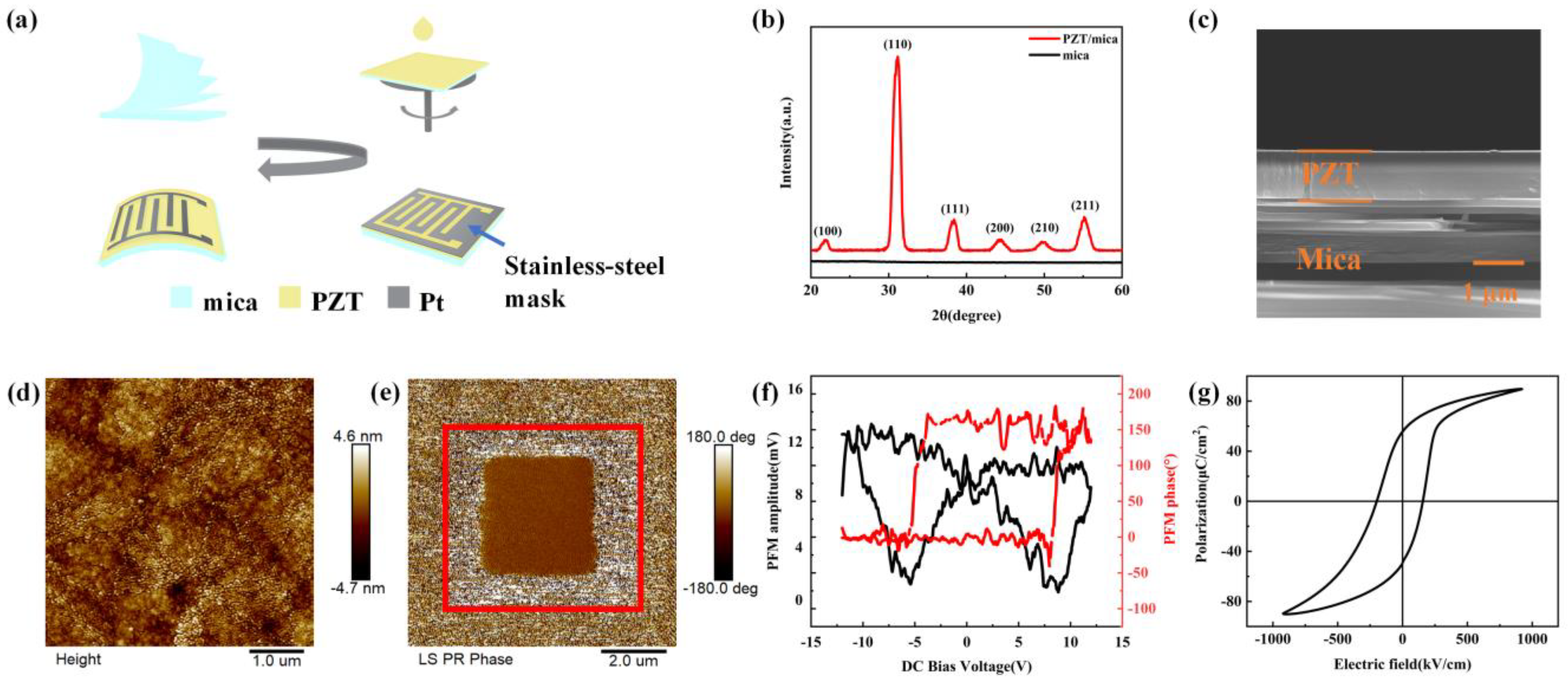
Figure 1a shows the diagram of the manufacturing steps of the PZT sensors. With exfoliation, spin-coating, and magnetron sputtering, the achieved Pt/PZT/mica structure can be bent; this was the basis of the good flexibility of the device. Figure 1b presents the grazing-incidence X-ray diffraction (GIXRD) patterns of the mica substrate, and PZT film on mica, respectively. The PZT films exhibited a polycrystalline perovskite structure without the presence of the pyrochlore phase; however, the preferred crystal orientation was found along the (110) direction. The characteristic peaks of the mica substrate were not detected in the diffraction pattern due to grazing-incident XRD geometry. Figure 1c presents a cross section of the PZT films; they exhibited a highly dense and smooth surface without any visible pores. The 20 layer PZT films were approximately 1 μm thick. The composition analysis was performed using energy dispersive spectroscopy (EDS), and the corresponding elemental mapping is shown in Figure S1 (see Supplementary Materials), in which the elements Pb, Zr, Ti, and O were uniformly distributed throughout the film. Figure 1d shows the roughness of the film within a 5 × 5 μm2 scanning area. The film exhibited a small root-mean-square roughness of 1.29 nm, an average roughness of 1.01 nm, and a height waviness of ~9.3 nm. Although it was in a 15 × 15 μm2 area, as shown in Figure S2, the height waviness was within 8 nm, which may be attributed to the atomically-scale flat surface of freshly stripped mica [37]. The height waviness, root-mean-square roughness, and average roughness of these mica were approximately 1 nm, 0.16 nm, and 0.13 nm, respectively, as shown in Figure S3.
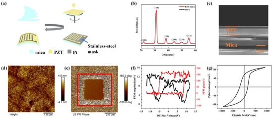
Figure 1.
Fabrication and characterization of the PZT film grown on the mica substrate. (a) Schematic diagrams of the PZT sensors’ fabrication process. (b) The GIXRD patterns and (c) cross-sectional SEM image of flexible PZT films on mica substrates. (d) AFM topography image of PZT films on mica substrates in a 5 × 5 µm2 area. (e) PFM phase image of PZT film after applying a local +12 V/−12 V DC voltage. (f) Amplitude and local PFM phase angle of PZT/LNO/mica. (g) P-E hysteresis loop of the Pt/PZT/LNO/mica.
As shown in Figure 1e, upward and downward biases (+12 V/−12 V) were conducted on different size areas of the films. It showed that the polarization of the domains rotated with the tip biases, thus demonstrating good ferroelectric switching behavior in the microscopic area. The piezoelectric loop was illustrated in Figure 1f. A clear butterfly-shaped and square piezoelectric loop further demonstrated an excellent piezoelectric response, and the 180° phase angle shift proved the good reversible polarization switching feature of the PZT films. Figure 1g shows the P-E hysteresis loop of the Pt/PZT/LNO/mica structure. The LaNiO3 layer acted as the bottom electrode due to its good conductivity and lattice match with the PbZr0.52Ti0.48O3. The remanent polarization (Pr) and saturation polarization (Ps) were 55 μC cm−2 and 90 μC cm−2, respectively, which were higher than those reported on Si substrates [38], due to the weak van der Waals interaction between PZT films and mica substrates [36,39]. Furthermore, it allows the maximum ferroelectric performance of the PZT films to be achieved due to easier domain switching [34,40]. The P-E loop had a dissymmetry of positive and negative coercive fields caused by upward self-polarization in the films.
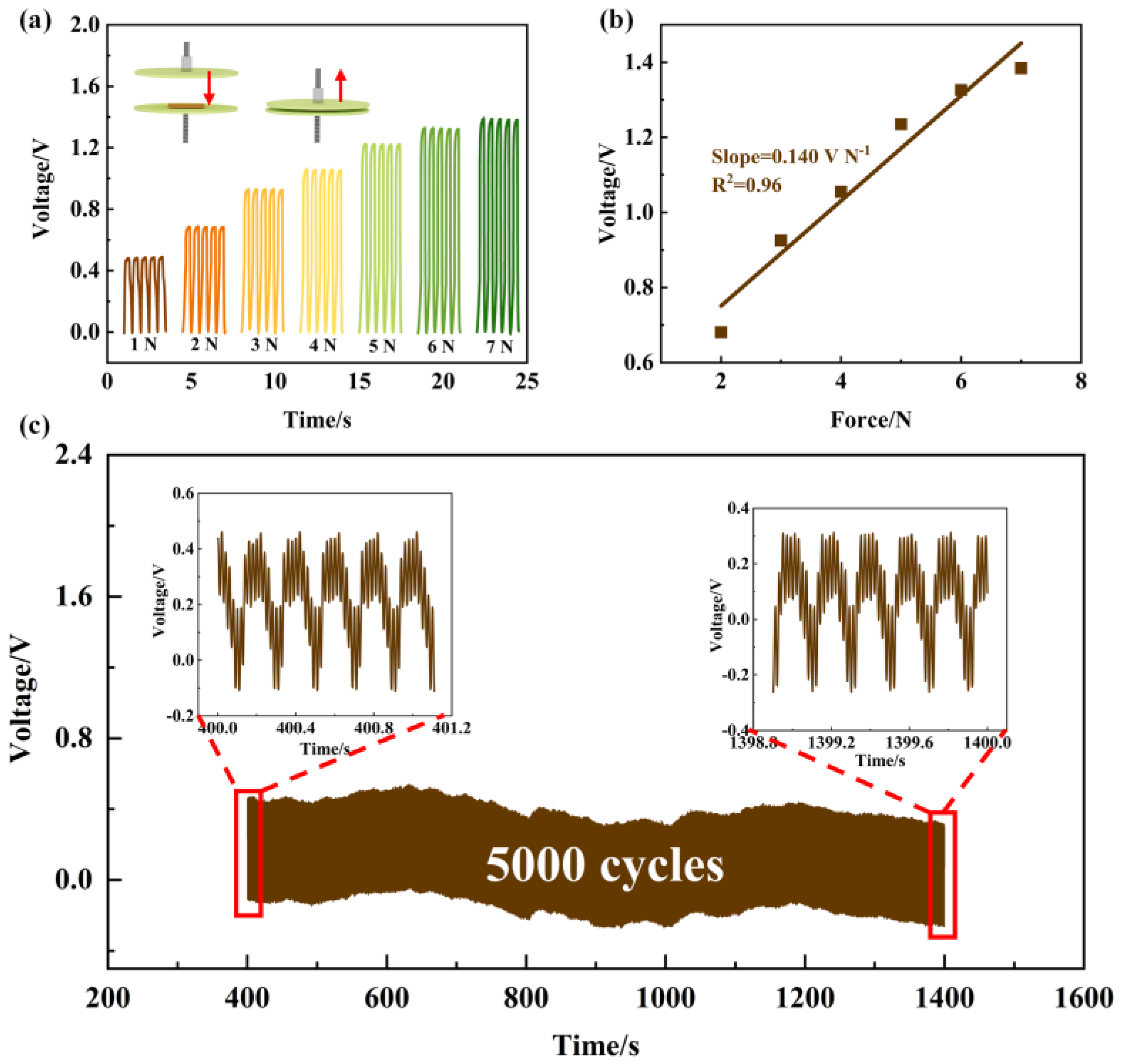
Figure 2a illustrates the voltage signal generated when tapping the sensor periodically, and the inset is a schematic of the external force applied. At the range from 1 N to 7 N, the open-circuit voltage output presented a growth trend with increased external force, and the maximal voltage was 1.38 V under force at 7 N. The sensitivity and the linearity of the flexible PZT sensor were 0.140 V N−1 and 0.96, respectively, thus demonstrating a high degree of linearity and the ability of the sensor to maintain a highly accurate output within a given force range. The stability performance of the PZT sensor was also evaluated with periodic tapping cycles. As shown in Figure 2c, the sensor survived the fatigue test with no degradation in performance. The output voltage remained unchanged before and after 5000 cycles, which is due to the sealed packaging of the sandwiched PI films; therefore, it showed satisfactory application stability. As shown in Figure S4, the current signals showed a similar growth trend in terms of voltage, and the sensitivity was 0.524 nA N−1; the response time was 36 ms.
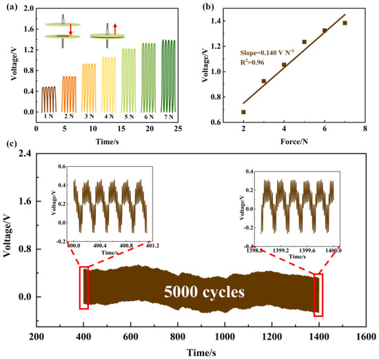
Figure 2.
Piezoelectric performance of the PZT sensor when the tapping mode was implemented. (a) Output voltages of the PZT sensor generated under vertical tapping. The inset is a schematic of the force applied. (b) Sensitivity of the mica-based PZT sensor. (c) Mechanical durability test of the flexible PZT sensor when subjected to a tapping frequency of 4 Hz over 5000 cycles.
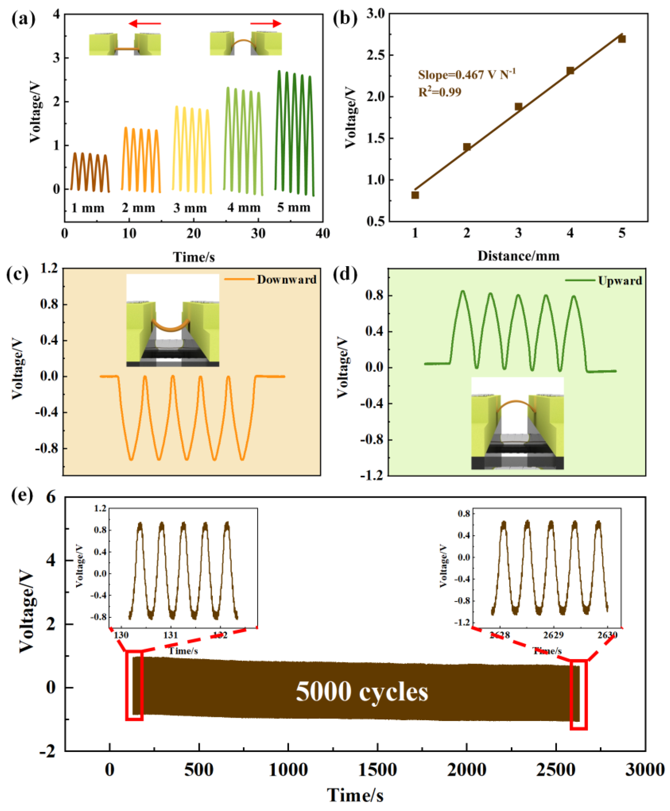
Figure 3 presents the performance of the flexible PZT sensor during the bending test. In the inset of Figure 3a, both ends of the piezoelectric sensor were fixed by the clamps of the bending equipment and it was driven to bend at a frequency of 2 Hz. As shown in Figure 3a, the peak voltage was 0.82 V when the compression distance was 1 mm. The voltage reached 2.7 V when the compression distance increased to 5 mm. The increased compression resulted in greater strain, thus leading to a large change in polarization. As a result, a greater piezoelectric potential was generated accordingly. The sensitivity of the mica-based PZT sensors during the bending mode was 0.467 V N−1, as shown in Figure 3b, with the linearity maintained at 0.99. It can be concluded that the voltage was positively correlated with the compression distance, and that a strong linear relationship exists between the two.
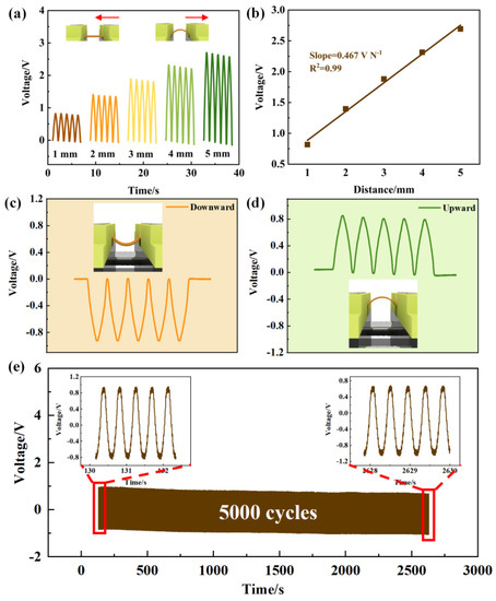
Figure 3.
Piezoelectric performance of the PZT sensor when the bending mode was implemented. (a) Output voltages of the PZT sensor generated when the bending mode was implemented. The inset is a schematic of the applied force mode. (b) Sensitivity of the PZT sensor. Positive and negative voltage signals generated by the PZT sensor bending (c) downward and (d) upward. (e) Mechanical durability test of the flexible PZT sensor at a bending frequency of 2 Hz over 5000 cycles.
To eliminate the triboelectric effect, the PZT sensor was bent up and down. The positive and negative voltage signals with comparable values were observed in Figure 3c,d, thus proving that the voltage was generated by the piezoelectric film [34,37]. Fatigue testing was carried out at a frequency of 2 Hz and a compression distance of 2 mm. The sensors maintained an output voltage at the same level as the original value of 1.6 V after 5000 cycles, thus demonstrating good potential longevity. The flexible mica-based PZT sensor exhibited good durability and accuracy over a small force range when both tapping and bending modes were implemented, thus making it suitable for monitoring minute vibrations in multiple deformation modes.
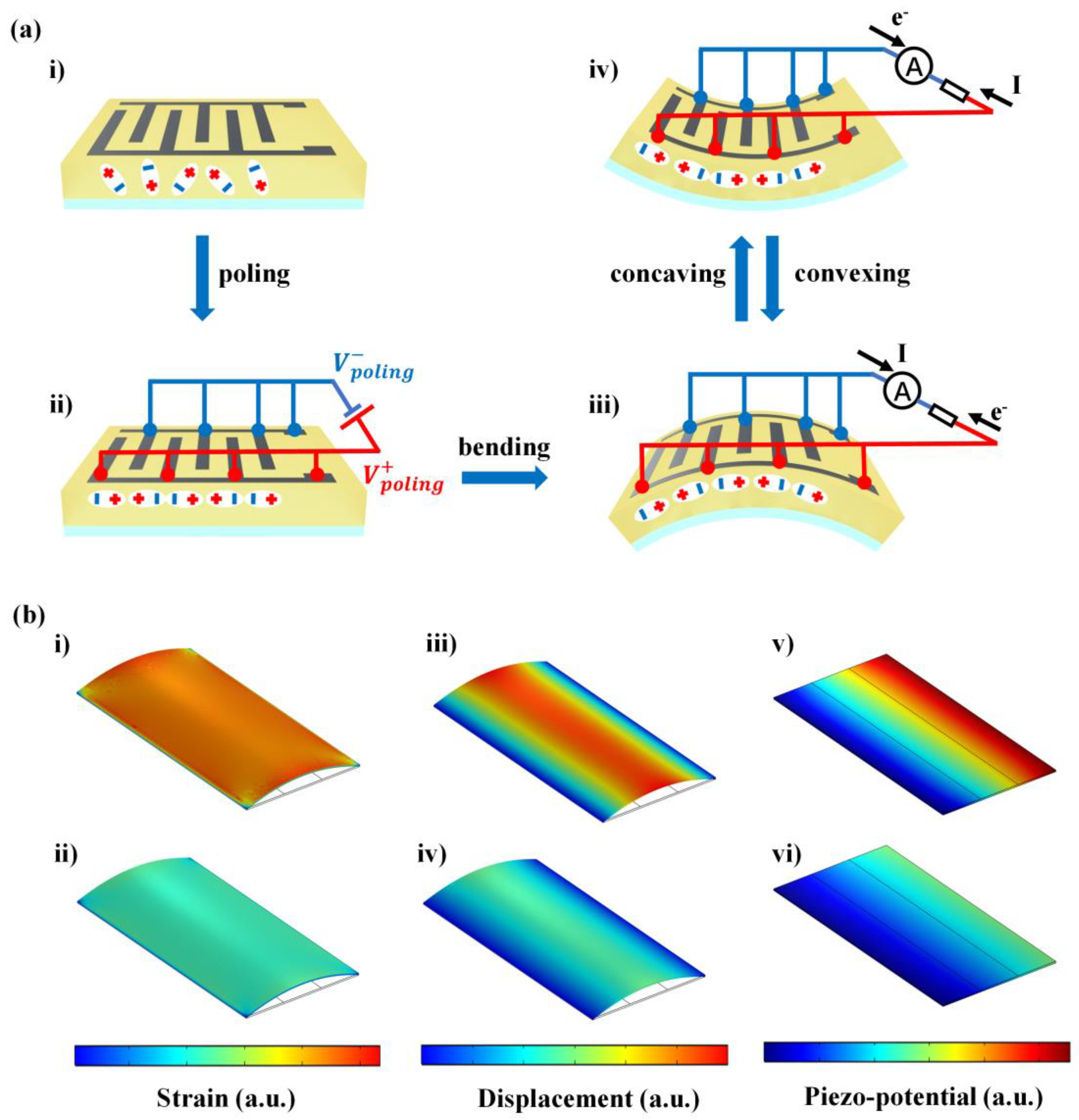
Figure 4a illustrates the working principle of the PZT sensor. During the poling process, the dipoles were aligned with the external electric field, which was parallel to the surface of the piezoelectric film between each pair of electrodes (Figure 4a-i,ii). The piezo-potential resulting from the bending deformation acted as the driving force for the electron flow through the external load (Figure 4a-iii). When the opposite force was applied, the dipole changed from stretching to compressing, and the electrons moved in the opposite direction, thus producing a reversed electrical signal (Figure 4a-iii,iv). Therefore, the alternative voltage peaks were generated when the PZT sensor periodically bent. In order to further reveal the piezo-potential of the PZT sensors when an external force was applied, a simplified simulation model was created and calculated using a Finite Element Analysis (FEA) method via COMSOL software. Figure 4b shows the results of the strain, displacement, and piezo-potential of the PZT sensor under different forces. For one set of calculation results, the resulting strain (Figure 4b-i,ii) and displacement (Figure 4b-iii,iv) corresponded with a piezo-potential (Figure 4b-v,vi) that existed at the two poles of the interdigitated electrodes. In accordance with the experimental results, an increase in strain and displacement was observed as the boundary load increased, leading to a growth trend in piezo-potential. Therefore, this demonstrates that the output voltage of the PZT sensors originates from changes in strain level.
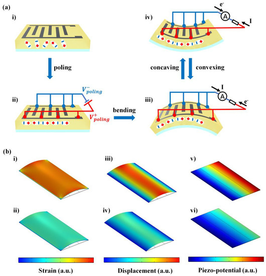
Figure 4.
Diagrams of the working mechanism and simulation results of the PZT sensor. (a) Illustrations of the working mechanism of the PZT sensor. (b) FEA simulation results of (i,ii) strain, (iii,iv) sisplacement, and (v,vi) piezo-potential when placed under the higher force and the lower force.
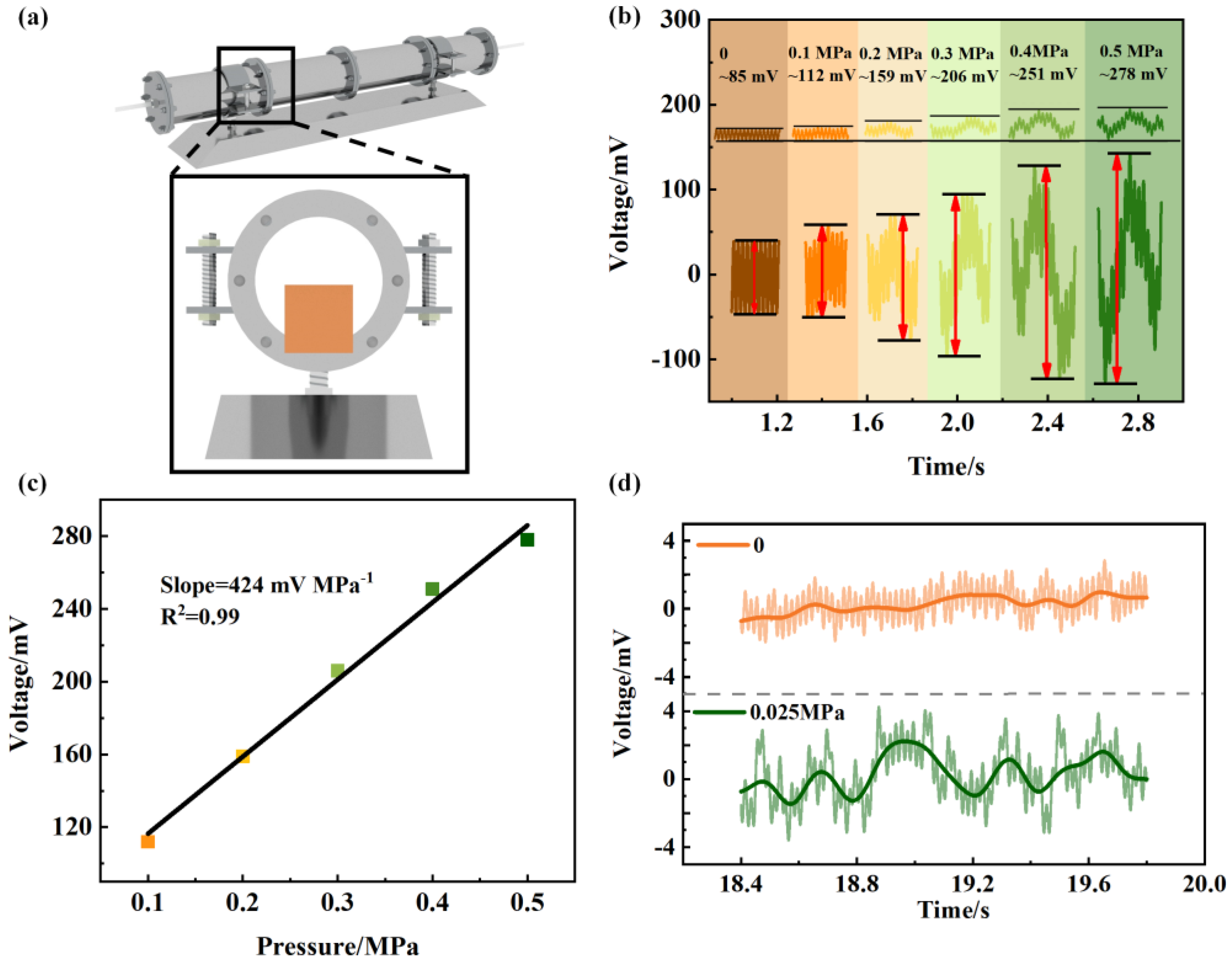
The pipe model and the position of the PZT sensor that was fixed between two sections of pipe are illustrated in Figure 5a. The sensor was attached to the end of the first pipe section, which was 10 cm away from the air inlet. A nitrogen cylinder was connected to the pipeline for its gas supply, and the barometer reading released pressure at the outlet of the nitrogen cylinder. The voltage signals were generated when air was flowing through the pipe under normal operating conditions. As shown in Figure 5b, the signal baseline was very smooth when no airflow passed through, with an initial value of 85 mV. As the pressure at the outlet increased, the airflow rate accelerated and the pressure on the sensor surface increased, resulting in a more intense deformation, which was reflected in the output voltage of the sensor. The stronger the vibration of the sensor, the greater the fluctuation of the signal. When the pressure at the outlet reached 0.5 MPa, the generated voltage was 278 mV; this equates to an increase of 227% compared with the voltage measured at zero pressure. The inset presents the original data of the signal peak. The growth trend produced a high slope and linearity of 424 mV Mpa−1 and 0.99 (Figure 5c). High linearity sensors not only provide accurate and reliable measurements, but they also accurately reflect changes in input parameters, thus indicating that the PZT sensor can be utilized for pressure monitoring in a normal working situation. The lower pressure detection limit of the PZT sensor was verified, as shown in Figure 5d. The raw data (light color) and smoothed data (dark color) of the baseline and minimum response signal are also shown. Compared with the stable baseline at 0 pressure, the PZT sensor produced an output voltage of 2 mV and a pressure change of 0.025 MPa. This demonstrates the ability of the PZT sensor to sensitively detect tiny changes in pressure.
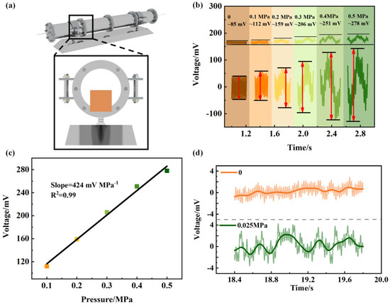
Figure 5.
Performance of the PZT sensor used in the gas pipe under normal working conditions. (a) Schematic image of the gas pipeline and the position of the PZT sensor at the pipe connection. (b) Output voltage generated using a different pressure. The inset shows the raw data of the signal peak. (c) Sensitivity and (d) lower limit of the PZT sensor.
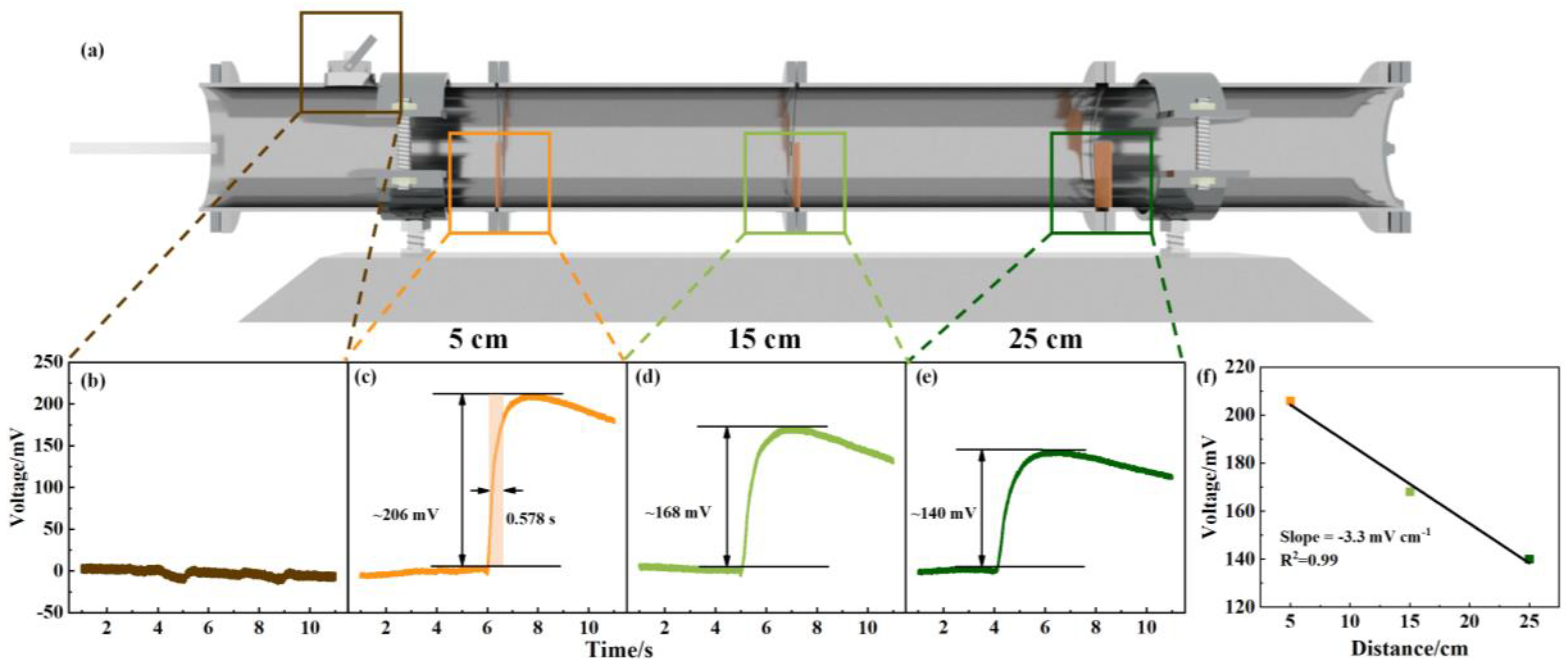
To investigate the viability of the mica-based PZT sensor for gas leak detection, the sensors were fixed in the pipe at different distances away from the valve. In order to provide a clear representation of the sensor positions, Figure 6a shows the corresponding cross section of the pipeline. The PZT sensor was fixed at 5 cm, 15 cm, and 25 cm away from the valve. At first, the leakage valve and pipeline ends were closed in order to pressurize the pipeline up to 0.3 MPa; then, the valve was switched on to simulate a leakage [41]. To exclude the influence of manual operation, the signals for opening and closing the valve at 0 pressure are shown in Figure 6b, and the effects of this proved to be negligible. Figure 6c–e show the voltage peaks generated by PZT sensors in different positions when a leakage occurred. As soon as the leakage happened, the upstream and downstream fluid went through the leakage point, and the flow velocity rapidly reached a maximum value [42], leading to pressure on the sensor’s surface. Due to the limited volume of the pipe, the gas leaked out instantaneously, and the sensor only produced a transient signal that peaked immediately, and then gradually declined. The effective response time of the sensor was 0.578 s (10–90% signal duration). According to Figure 6c–e, the decrease in output voltage was related to the distance from the sensor to the valve, and a slower flow rate resulted in less deformation. The output signal versus distance is further illustrated in Figure 6f, and the strong linearity implies that an accurate leak location can be determined from the response of the sensor.
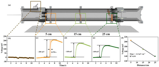
Figure 6.
Performance of the PZT sensor used in the gas pipe when leakage conditions were implemented. (a) Schematic image of the position of the leakage valve and PZT sensors. Output voltage generated by (b) the valve opening and closing and for gas leakage when the PZT sensor was at a distance of (c) 5 cm, (d) 15 cm, and (e) 25 cm away from the valve. (f) Sensitivity of the PZT sensor between the output voltage and distance from the valve.
The mica-based PZT sensors in this work can respond directly (0.578 s) to the mechanical deformation caused by airflows; this is much faster than the self-powered active gas sensors (>10 s) [43,44,45,46] used in leakage or gas monitoring. Moreover, compared with the mica-based PZT sensors, the self-powered active gas sensors suffer from specific gas selectivity, which further delays timely action, thus resulting in limited application scenarios. In the future, an array of piezoelectric sensors are required to comprehensively monitor gas pipeline networks over long-distances for structural health monitoring purposes. Therefore, the flexible mica-based PZT sensor offers a promising solution for timely airflow detection. Moreover, the reduced response time plays a crucial role in triggering the alarm in a timely manner, accurate leakage detection, and enabling prompt action to be taken in terms of practical applications.
4. Conclusions
In summary, flexible PZT films with smooth surfaces and no apparent cracks were successfully fabricated using the sol-gel method on a mica substrate. The PZT sensor exhibited good stability and flexibility when both the vertical-tapping and bending modes were implemented; after 5000 cycles, it exhibited a maximum peak voltage of 1.38 V and 2.7 V, respectively. It exhibited short response time (0.578 s) and high sensitivity (3.3 mV cm−1) in the event of a gas pipeline leakage, and the output voltage was closely related to the location of the leakage point, thus providing a reliable reference for the timely warning and location of the leakage point. This work provides a basis for the future development of flexible piezoelectric sensors in the structural health monitoring field.
Supplementary Materials
The following supporting information can be downloaded at: https://www.mdpi.com/article/10.3390/cryst13060855/s1. Figure S1. The cross-sectional SEM and EDS results of element distribution in PZT film. Figure S2. AFM results of different scanning areas of 1 × 1 μm2, 3 × 3 μm2, 10 × 10 μm2, and 15 × 15 μm2 in PTZ film. Figure S3. AFM results of 15 × 15 μm2 in freshly stripped mica. Figure S4. (a) The output current of the PZT sensor generated under vertical tapping. (b) Sensitivity of the PZT sensor. (c) Responding time of the PZT sensor to an applied stimulus.
Author Contributions
Conceptualization, M.J.; software, W.Z. and D.Z.(Di Zhai); validation, M.J. and Q.X.; formal analysis, M.J. and S.J.; investigation, M.J. and M.T.; data curation, M.J. and M.Y.; writing—original draft preparation, M.J.; writing—review and editing, Y.Z. and D.Z. (Dou Zhang). All authors have read and agreed to the published version of the manuscript.
Funding
This research was funded by the National Key R&D Program of China (No. 2022YFB3807404). This work was also supported by Overseas Talent Introduction Project of China, Hundred Youth Talents Program of Hunan and National Natural Science Foundation of China (Nos. U19A2087, 52204263).
Data Availability Statement
Not applicable.
Conflicts of Interest
The authors declare no conflict of interest.
References
- Davoodi, S.; Mostafapour, A. Modeling Acoustic Emission Signals Caused by Leakage in Pressurized Gas Pipe. J. Nondestr. Eval. 2012, 32, 67–80. [Google Scholar] [CrossRef]
- Song, Y.; Li, S. Gas Leak Detection in Galvanised Steel Pipe with Internal Flow Noise Using Convolutional Neural Network. Process Saf. Environ. Prot. 2021, 146, 736–744. [Google Scholar] [CrossRef]
- Spandonidis, C.; Theodoropoulos, P.; Giannopoulos, F.; Galiatsatos, N.; Petsa, A. Evaluation of Deep Learning Approaches for Oil & Gas Pipeline Leak Detection Using Wireless Sensor Networks. Eng. Appl. Artif. Intell. 2022, 113, 104890. [Google Scholar]
- Zhou, Z.; Zhang, J.; Huang, X.; Guo, X. Experimental Study on Distributed Optical-Fiber Cable for High-Pressure Buried Natural Gas Pipeline Leakage Monitoring. Opt. Fiber Technol. 2019, 53, 102028. [Google Scholar] [CrossRef]
- Parra-Raad, J.A.; Roa-Prada, S. Multi-Objective Optimization of a Magnetic Circuit for Magnetic Flux Leakage-Type Non-destructive Testing. J. Nondestr. Eval. 2016, 35, 14. [Google Scholar] [CrossRef]
- Jiang, T.; Ren, L.; Wang, J.; Jia, Z.; Li, D.; Li, H. Experimental Investigation of Fiber Bragg Grating Hoop Strain Sensor–Based Method for Sudden Leakage Monitoring of Gas Pipeline. Struct. Health Monit. 2020, 20, 3024–3035. [Google Scholar] [CrossRef]
- Ren, L.; Jiang, T.; Jia, Z.; Li, D.; Yuan, C.; Li, H. Pipeline Corrosion and Leakage Monitoring Based on the Distributed Optical Fiber Sensing Technology. Measurement 2018, 122, 57–65. [Google Scholar] [CrossRef]
- Datta, S.; Sarkar, S. A Review on Different Pipeline Fault Detection Methods. J. Loss Prev. Process Ind. 2016, 41, 97–106. [Google Scholar] [CrossRef]
- Long, Y.; Zhang, J.; Huang, S.; Peng, L.; Wang, W.; Wang, S.; Zhao, W. A Novel Crack Quantification Method for Ultra-High-Definition Magnetic Flux Leakage Detection in Pipeline Inspection. IEEE Sens. J. 2022, 22, 16402–16413. [Google Scholar] [CrossRef]
- Ru, G.; Gao, B.; Liu, D.; Ma, Q.; Li, H.; Woo, W.L. Structural Coupled Electromagnetic Sensing of Defects Diagnostic System. IEEE Trans. Ind. Electron. 2023, 70, 951–964. [Google Scholar] [CrossRef]
- Ghasemi, P.; Sharifi, M.J. Optoelectronic Memory Capacitor Based on Manipulation of Ferroelectric Properties. ACS Appl. Mater. Interfaces 2021, 13, 53067–53072. [Google Scholar] [CrossRef] [PubMed]
- Xu, S.; Hansen, B.J.; Wang, Z.L. Piezoelectric-Nanowire-Enabled Power Source for Driving Wireless Microelectronics. Nat. Commun. 2010, 1, 93. [Google Scholar] [CrossRef] [PubMed]
- Dagdeviren, C.; Su, Y.; Joe, P.; Yona, R.; Liu, Y.; Kim, Y.S.; Huang, Y.; Damadoran, A.R.; Xia, J.; Martin, L.W.; et al. Conformable Amplified Lead Zirconate Titanate Sensors with Enhanced Piezoelectric Response for Cutaneous Pressure Monitoring. Nat. Commun. 2014, 5, 4496. [Google Scholar] [CrossRef]
- Yalcinkaya, H.; Ozevin, D. The Design and Calibration of Particular Geometry Piezoelectric Acoustic Emission Transducer for Leak Detection and Localization. Meas. Sci. Technol. 2013, 24, 095103. [Google Scholar] [CrossRef]
- Zhang, M.; Chen, X.; Li, W. Hidden Markov Models for Pipeline Damage Detection Using Piezoelectric Transducers. J. Civ. Struct. Health Monit. 2021, 11, 745–755. [Google Scholar] [CrossRef]
- Feng, Q.; Kong, Q.; Huo, L.; Song, G. Crack Detection and Leakage Monitoring on Reinforced Concrete Pipe. Smart Mater. Struct. 2015, 24, 115020. [Google Scholar] [CrossRef]
- Liu, H.; Zhang, S.; Kathiresan, R.; Kobayashi, T.; Lee, C. Development of Piezoelectric Microcantilever Flow Sensor with Wind-Driven Energy Harvesting Capability. Appl. Phys. Lett. 2012, 100, 223905. [Google Scholar] [CrossRef]
- Ejeian, F.; Azadi, S.; Razmjou, A.; Orooji, Y.; Kottapalli, A.; Ebrahimi Warkiani, M.; Asadnia, M. Design and Applications of MEMS Flow Sensors: A review. Sens. Actuators A 2019, 295, 483–502. [Google Scholar] [CrossRef]
- Hu, J.; Chen, J.; Liu, P.; Fan, S.; Duan, W. Near-Field Electrospinning-Enabled Direct-Write P(VDF-TrFE) Nano/Micro-Fiber-Based Piezoelectric Film for A High-Performance Airflow Sensor. Sens. Actuators A 2022, 336, 113399. [Google Scholar] [CrossRef]
- Corzo, D.; Tostado-Blázquez, G.; Baran, D. Flexible Electronics: Status, Challenges and Opportunities. Front. Electron. 2020, 1, 594003. [Google Scholar] [CrossRef]
- Kong, H.; Sun, W.; Zhou, H. Progress in Flexible Perovskite Solar Cells with Improved Efficiency. J. Semicond. 2021, 42, 101605. [Google Scholar] [CrossRef]
- Wang, X.; Lee, C.; Peng, C.; Chen, P.; Chang, P. A Micrometer Scale and Low Temperature PZT Thick Film MEMS Process Utilizing An Aerosol Deposition Method. Sens. Actuators A 2008, 143, 469–474. [Google Scholar] [CrossRef]
- Qi, Y.; Jafferis, N.T.; Lyons, K., Jr.; Lee, C.M.; Ahmad, H.; McAlpine, M.C. Piezoelectric Ribbons Printed onto Rubber for Flexible Energy Conversion. Nano Lett. 2010, 10, 524–528. [Google Scholar] [CrossRef]
- Pesquera, D.; Khestanova, E.; Ghidini, M.; Zhang, S.; Rooney, A.P.; Maccherozzi, F.; Riego, P.; Farokhipoor, S.; Kim, J.; Moya, X.; et al. Large Magnetoelectric Coupling in Multiferroic Oxide Heterostructures Assembled via Epitaxial Lift-Off. Nat. Commun. 2020, 11, 3190. [Google Scholar] [CrossRef]
- Park, K.I.; Son, J.H.; Hwang, G.T.; Jeong, C.K.; Ryu, J.; Koo, M.; Choi, I.; Lee, S.H.; Byun, M.; Wang, Z.L.; et al. Highly-Efficient, Flexible Piezoelectric PZT Thin Film Nanogenerator on Plastic Substrates. Adv. Mater. 2014, 26, 2514–2520. [Google Scholar] [CrossRef]
- Zhu, C.; Guo, D.L.; Ye, D.; Jiang, S.; Huang, Y.A. Flexible PZT-Integrated, Bilateral Sensors via Transfer-Free Laser Lift-Off for Multimodal Measurements. ACS Appl. Mater. Interfaces 2020, 12, 37354–37362. [Google Scholar] [CrossRef]
- Zhong, G.; An, F.; Qu, K.; Dong, Y.; Yang, Z.; Dai, L.; Xie, S.; Huang, R.; Luo, Z.; Li, J. Highly Flexible Freestanding BaTiO3-CoFe2O4 Heteroepitaxial Nanostructure Self-Assembled with Room-Temperature Multiferroicity. Small 2022, 18, 2104213. [Google Scholar] [CrossRef]
- Park, D.Y.; Joe, D.J.; Kim, D.H.; Park, H.; Han, J.H.; Jeong, C.K.; Park, H.; Park, J.G.; Joung, B.; Lee, K.J. Self-Powered Real-Time Arterial Pulse Monitoring Using Ultrathin Epidermal Piezoelectric Sensors. Adv. Mater. 2017, 29, 1702308. [Google Scholar] [CrossRef]
- Lee, H.S.; Chung, J.; Hwang, G.T.; Jeong, C.K.; Jung, Y.; Kwak, J.H.; Kang, H.; Byun, M.; Kim, W.D.; Hur, S.; et al. Flexible Inorganic Piezoelectric Acoustic Nanosensors for Biomimetic Artificial Hair Cells. Adv. Funct. Mater. 2014, 24, 6914–6921. [Google Scholar] [CrossRef]
- Gabrielsson, E.O.; Jung, Y.H.; Han, J.H.; Joe, D.J.; Simon, D.T.; Lee, K.J.; Berggren, M. Autonomous Microcapillary Drug Delivery System Self-Powered by a Flexible Energy Harvester. Adv. Mater. Technol. 2021, 6, 2100526. [Google Scholar] [CrossRef]
- Zhang, B.; Yun, C.; MacManus-Driscoll, J.L. High Yield Transfer of Clean Large-Area Epitaxial Oxide Thin Films. Nano Micro Lett. 2021, 13, 39. [Google Scholar] [CrossRef] [PubMed]
- Li, D.; Adamo, C.; Wang, B.Y.; Yoon, H.; Chen, Z.; Hong, S.S.; Lu, D.; Cui, Y.; Hikita, Y.; Hwang, H.Y. Stabilization of Sr3Al2O6 Growth Templates for Ex Situ Synthesis of Freestanding Crystalline Oxide Membranes. Nano Lett. 2021, 21, 4454–4460. [Google Scholar] [CrossRef] [PubMed]
- Jin, C.; Zhu, Y.; Li, X.; An, F.; Han, W.; Liu, Q.; Hu, S.; Ji, Y.; Xu, Z.; Hu, S.; et al. Super-Flexible Freestanding BiMnO3 Membranes with Stable Ferroelectricity and Ferromagnetism. Adv. Sci. 2021, 8, 2102178. [Google Scholar] [CrossRef] [PubMed]
- Wang, D.; Yuan, G.; Hao, G.; Wang, Y. All-Inorganic Flexible Piezoelectric Energy Harvester Enabled by Two-Dimensional Mica. Nano Energy 2018, 43, 351–358. [Google Scholar] [CrossRef]
- Zou, D.; Liu, S.; Zhang, C.; Hong, Y.; Zhang, G.; Yang, Z. Flexible and Translucent PZT Films Enhanced by the Compositionally Graded Heterostructure for Human Body Monitoring. Nano Energy 2021, 85, 105984. [Google Scholar] [CrossRef]
- Er, X.; Wang, H.; Shao, P.; Ma, Q.; Chu, Y.; Zhan, Q. The Microstructure and Ferroelectric Properties of PbZr0.52Ti0.48O3 Films on Mica Substrates. Ceram. Int. 2021, 47, 9252–9257. [Google Scholar] [CrossRef]
- Lv, P.; Qian, J.; Yang, C.; Liu, T.; Wang, Y.; Wang, D.; Huang, S.; Cheng, X.; Cheng, Z. Flexible All-Inorganic Sm-Doped PMN-PT Film with Ultrahigh Piezoelectric Coefficient for Mechanical Energy Harvesting, Motion Sensing, and Human-Machine Interaction. Nano Energy 2022, 97, 107182. [Google Scholar] [CrossRef]
- Nguyen, M.D.; Houwman, E.P.; Dekkers, M.; Rijnders, G. Strongly Enhanced Piezoelectric Response in Lead Zirconate Titanate Films with Vertically Aligned Columnar Grains. ACS Appl. Mater. Interfaces 2017, 9, 9849–9861. [Google Scholar] [CrossRef] [PubMed]
- Yen, M.; Bitla, Y.; Chu, Y. van der Waals Heteroepitaxy on Muscovite. Mater. Chem. Phys. 2019, 234, 185–195. [Google Scholar] [CrossRef]
- Qi, H.; Yang, J.; Chen, H.; Wang, C.; Tao, J.; Dai, W.; Wu, T.; Li, J. Influence of Substrate Thickness on the Electrical Properties of Flexible PbZr0.52Ti0.48O3 Thin Films Grown on Mica. J. Electron. Mater. 2020, 49, 5449–5454. [Google Scholar] [CrossRef]
- Zhu, J.; Ren, L.; Ho, S.; Jia, Z.; Song, G. Gas Pipeline Leakage Detection Based on PZT Sensors. Smart Mater. Struct. 2017, 26, 025022. [Google Scholar] [CrossRef]
- Oke, A.; Mahgerefteh, H.; Economou, I.; Rykov, Y. A Transient Outflow Model for Pipeline Puncture. Chem. Eng. Sci. 2003, 58, 4591–4604. [Google Scholar] [CrossRef]
- Nie, Y.; Deng, P.; Zhao, Y.; Wang, P.; Xing, L.; Zhang, Y.; Xue, X. The Conversion of PN-Junction Influencing the Piezoelectric Output of A CuO/ZnO Nanoarray Nanogenerator and Its Application as A Room-Temperature Self-Powered Active H2S Sensor. Nanotechnology 2014, 25, 265501. [Google Scholar] [CrossRef]
- Sardana, S.; Kaur, H.; Arora, B.; Aswal, D.K.; Mahajan, A. Self-Powered Monitoring of Ammonia Using an MXene/TiO2/Cellulose Nanofiber Heterojunction-Based Sensor Driven by an Electrospun Triboelectric Nanogenerator. ACS Sens. 2022, 7, 312–321. [Google Scholar] [CrossRef]
- Chang, J.; Zhu, C.; Wang, Z.; Wang, Y.; Li, C.; Hu, Q.; Xu, R.; Du, T.; Xu, M.; Feng, L. A Full-Set and Self-Powered Ammonia Leakage Monitor System Based on CNTs-PPy and Triboelectric Nanogenerator for Zero-Carbon Vessels. Nano Energy 2022, 98, 107271. [Google Scholar] [CrossRef]
- Fu, Y.; Nie, Y.; Zhao, Y.; Wang, P.; Xing, L.; Zhang, Y.; Xue, X. Detecting Liquefied Petroleum Gas (LPG) at Room Temperature Using ZnSnO3/ZnO Nanowire Piezo-Nanogenerator as Self-Powered Gas Sensor. ACS Appl. Mater. Interfaces 2015, 7, 10482–10490. [Google Scholar] [CrossRef]
Disclaimer/Publisher’s Note: The statements, opinions and data contained in all publications are solely those of the individual author(s) and contributor(s) and not of MDPI and/or the editor(s). MDPI and/or the editor(s) disclaim responsibility for any injury to people or property resulting from any ideas, methods, instructions or products referred to in the content. |
© 2023 by the authors. Licensee MDPI, Basel, Switzerland. This article is an open access article distributed under the terms and conditions of the Creative Commons Attribution (CC BY) license (https://creativecommons.org/licenses/by/4.0/).

